1
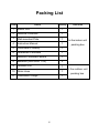
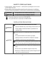
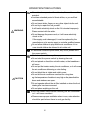
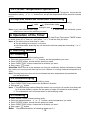
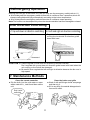
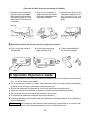
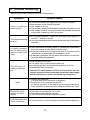
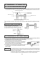
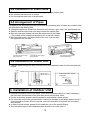
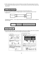
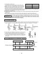
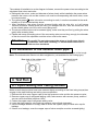
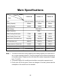
Applicable to
CSRA-09
CSRA-12
CSRA-18
Split Type Wall-mounted Room Air Conditioner
Instruction Manual
Thank you for purchasing of CITIZEN air conditioner. To
guarantee safety and best efficiency, please read this manual
carefully and keep a suitable storage for reference.
To Consumers
1. The air conditioner should be installed and repaired by the qualified professional technicians
according to this manual.
2. The air conditioner must be earthed reliably in installation.
3. Please pull out the plug (shut the power) when it is not in use,especial in the following
situations:
In disused seasons In thunderstorm weather.
4. Please clean the air filter nets 1-2 times per month when the air conditioner is in using season
(detailed in inner pages).
Features:
Adopt the world famous compressor and micro computer controlling chip, the
performance is stable and reliable.
High-efficiency compressor and heat exchanger are adopted to guarantee
higher efficiency and energy-saving.
Adopt random pitch fan, big fan wheel and stepping motor to drive fan, achieve
quiet running.
Note:
Some contents in this manual might be changed as the renewal of products , if there are
any differences with the material objects, please take the material objects as standard,
pardon us for not giving extra notice.
1
Packing List
Order
Name
Quantity
Remarks
1
Indoor Unit
1
2
Remove Controller
1
3
Wall-mounted Plate
1
In the indoor unit
4
Instruction Manual
1
packing box
5
Certificate of Quality
1
6
Guarantee Certificate
1
7
Remote Controller s Brace
1
8
Batteries (AAA SIZE 1.5V)
2
9
Outdoor Unit
1
10
Drain Hose
1
11
Catchment Trough
1
,
In the outdoor unit
packing box
2
SAFETY PRECAUTIONS
Please read theSafety Precautioncarefully before operating the unit to ensure
correct usage of the unit.
Please observe the following safety precautions when using your air conditioner.
If you fail to observe the precautions, it could cause fire, electrical shock or personalinjury.
WARNING
This sign warns of risk of death or serious injury.
CAUTION
This sign warns of injury or damage to property.
This symbol denotes an action that is PROHIBITED.
This symbol denotes an action that is COMPULSORY.
INSTALLATION PRECAUTIONS
Do not install, removed and reinstall the unit yourself.
WARNING
Improper installation may cause leakage, electric shock or fire.
Please engage an authorized dealer or specialist for the
installation work.
Please use earth line. Improper grounding could cause electric
shock.
Do not place the earth line near water or gas pipes,
lightning-conductor or the earth line of telephone. Improper
CAUTION
installation of earth line may cause electric shock.
Do not install the unit in a place where there are explosive gas
leaks. The unit may catch fire if flammable gas leaks around it.
Please ensure smooth flow of water when installing the drain
hose.
For the indoor unit installation height is at least 2.0m.
If the fuse on PCB board is broken, please change the same
type fuse by professional person.
3
OPERATION PRECAUTIONS
Do not touch or operate with wet hands, this could cause fatal
accident.
Avoid an extended period of direct airflow, or you well feel
uncomfortable.
Do not insert sticks, fingers or any other object into the unit.
Do not try to repair the unit yourself.
It will lead to electricity shock or fire if it is treated improperly.
WARNING
Please contact with the seller.
Do not damage the power cord, or it will cause electricity
shock or fire.
If the supply cord is damaged, it must be replaced by the
manufacturer or its service agent or a similar qualified person.
Do not allow children to play with the air conditioner. In no
case should children be allowed to sit on the unit.
If abnormal conditions (burnt smell, etc) occur, please shut
the power switch.
Do not use the unit for any other purpose.
Do not shut the power switch by drawing the cord.
Do not splash or direct the unit with water, or the breakdown
will occur.
Do not put the heater nearby the air conditioner, or it will cause
the air conditioner deforming or color fading.
Do not block the air intake and outlet vanes.
Do not let the air conditioner overload for a long time.
CAUTION
eg: the temperature of outdoor is very high or the place that the
doors and windows are open.
Do not operate without the air filter installed or when the front
intake grille has been removed.
Do not place anything on the unit.
Shut the power switch before cleaning the air conditioner
or it will cause accident.
Please ensure proper ventilation when in use, extra attention
should be paid where there is coal gas facility.
4
Contents
To Consumers 1
Features 1
Packing List2
Safety Precautions
3
Part : Operation Instruction
Parts Names and Functions 6
Preparations before Operation 9
Operation Contents Setting
9
Operation of Timer 10
Running Mode 10
Air Direction Controlling 11
Maintenance Method ë11
Operation Experience Guide 12
Trouble Shooting 13
Part : Installation Instruction
Select the Location for Installation 14
Installation of Indoor Unit 15
Installation of Outdoor Unit
16
Test Run 19
Main Specifications 21
5
Part Operation Instruction
1.Parts Names and Functions
1-1 Indoor Unit
Intake vent
Signal receiving window
Outlet vent
Indicator Iamps
Air filter nets(2)
Emergency Switch
CSRA-09
Intake vent
Signal receiving window
Outlet vent
Indicator lamps
Air filter nets(2)
CSRA-12
6
Emergency Switch
Intake vent
Indicator Iamps
Outlet vent
Signal receiving window
Air filter nets(2)
Auxiliary buckle(4)
CSRA-18
Emergency Switch
1-2 Outdoor Unit
Intake vent
Intake vent
Outlet vent
Outlet vent
CSRA-18
CSRA-09,CSRA-12
7
1-3 Remote Controller
Display Section
Operation Section
Infrared transmit tube
Transmit signal to indoor unit
Mode key
Choose cooling/dehumidifying/heating
Temperature setting key(16J30)
Wind speed key
Choose Low/Medium/High/Auto
Air direction adjusting key
Timer key
Timer on/off/cancel
Liquid crystal display
Time setting key (1-18hr)
Switch key
(on/off)
Remote Controller’s Brace
Slide upwards
Insert
downwards
Screw
Fix brace
Set remote controller
Remove remote controller
(to use at hand)
Fix brace at convenient place near to indoor unit.
Directions: Signal transmitting display:
Mode display:
cooling
dehumidifying
heating
Temperature setting display:
Wind speed display :
low
medium
high
automatic
Air direction display:
(Air direction adjusting)
Timer display:
Timer setting display:
8
1. There may be difference between the temperature set by the remote controller (The air
2.
3.
4.
5.
conditioner will stop working while cooling or heating reach this temperature) and measured
by temperature measuring device. You can regulate the temperature you want only by the
remote controller.
It is not certain that the room temperature can reach the temperature displayed on the remote
controller. Only when the room area is proper, the heat preservation is very good, etc ., can they
match each other. So, the temperature set by the remote controller and the temperature the
room can get are two different concepts.
The displaying temperature on the remote controller is the set temperature.
The speed of indoor fan has three grades: high speed grade, low speed grade and breeze
grade (the breeze grade can’t be controlled by man but by microcomputer automatically). The
remote controller transmit “mid-speed” signal,main frame will dispose it as low speed
automatically.
The remote controller should be aimed at the receiving window of the main frame which will
send out a “du” sound when the signal is received.
2. Preparations before Operation
2-1 Usage of Batteries
1. Remove the back cover of the remote controller according to
the arrow direction.
2. Fill in two AAA size 1.5V batteries after confirming the porlarities.
3. Reinstall the back cover.
2-2 Operation of the Remote Controller
Aim the signal transmitting tube to the signal receiving window of the indoor unit.
There should be nothing between the remote controller and the signal receiving window.
Avoid violent bumping.
Avoid direct sunshine, heater and other heat resources.
The remote controller should be kept clean and dry.
Please adopt two AAA size 1.5V batteries with same brand.
The batteries should be taken out if the unit won’t be used for a long period of time.
Change another two new batteries if the relative contents can’t be displayed clearly on the
LCD of the remote controller or the distance of controlling turns short obviously.
Never mix the new battery with the old one.
3. Operation Contents Setting
3-1 Illustration of Indicating Lamps
Running lamp (green):on: The conditions satisfy the compressor to work.
flash: The unit is in the anti cold wind state of defoosting state.
out: The compressor does not work.
Timer lamp (yellow)on: Indicate the air conditioner is timed to on or off.
Protection lamp (red) flash: Indicate the air conditioner is abnomal, please notify the serviceman.
9
3-2 Pre-set Temperature Operation
Press “MODE” button and select “cooling” or “heating” (Heat Pump Type)mode, then press the
temperature setting “ ” or “ ” button once, the pre-set temperature will be raised or lowered
by 1.
3-3 Up and Down Air Direction Controlling
Press the air “DIRECTION” button, the ventilating door will act in turns as following:
static
up and down swing
change in turn
If
you
need
different
static
angle.
Press “DIRECTION” button when the automatic up and
Note:
down louver move to the position you want.
4. Operation of the Timer
In the mode of “cooling”or “dehumidifying” or “heating” (Heat Pump Type) press “TIMER” button
to select “timer off” or “timer on”, then press “-” or “+” to set the time you need.
Note: The initial value of timer time is 1 hour.
The pre-setting time range is 1-18 hours.
In the timer state, press any key, will cancel the set time except the time setting “-” or “+”
buttons.
5. Running Mode
5-1 Cooling
Press “MODE” button, select cooling mode.
Press pre-set temperature “ ” “ ” buttons, set the temperature you need.
Press “SPEED” button, choose the fan speed you need.
Press “DIRECTION.” button choose the air direction you want.
Stop, press “ ” button.
Attention: When it turns to the seasons not using air conditioner (before maintenance), keep
the indoor unit running more than half an hour (method: In cooling mode,set temperature at
30).
Note: Running lamp turns from on to out indicates the room temperature has reached the
pre-set temperature.
5-2 Dehumidifying
Press “MODE” button,choose dehumidifying mode.
Press “DIRECTION” button,choose the suitable air direction.
Stop,press “ ” button.
Note: 1. The dehumidifying method: Keep the outdoor unit running for 10 minutes, then keep rest
for 5 minutes,repeat in cycles, the fan speed of indoor unit should be at low speed.
2. The temperature can’t be pre-set when in dehumidifying mode.
5-3 Heating
Press “MODE” button, choose heating mode.
Press pre-set temperature “ ” or “ ” buttons, set the temperature you need.
Press “SPEED” button, choose the fan speed you need.
Press “DIRECTION” button, choose the air direction you want.
Stop, press “ ” button.
Note: The detailed directions of indicating lamps see 3-1.
10
5-4Emergency Operation
Remove the front girll of the indoor unit ,and you may see the emergency switch(refer to1-1)
At“off”state,press the emergency switch button,the air coditioner then it operation,which will
choose cooling/dehumidifying automatically according to the indoor temperature.
At“on”state,press the emergency switch button,the air coditioner stops operating.
Note:The function can be adopted only when the remote controller has been damaged or missed.
6.Air Direction Controlling
6-1 Up and down air direction controlling 6-2 Left and right air direction controlling
The detailed operation see 3-3.
Regulate the left and right air direction by
moving the horziontal air direction guide
board with hand.
45°
downward
CAUTION Please regulate up and down air direction by remote controller.
Don’t regulate the up and down air direction guide board with hand when the
unit running, or the link will be damaged.
Be careful when regulate the left and right air direction because the fan runs in
high speed.
7. Maintenance Methods
Clean the remote controller
Clean the intake vent grille
Dip the cloth into the cold water or warm
Wash it with soft things similar as sponge
water under 40twist it and then rub the
unit.
If it is very dirty, the neutral detergent solu-
and then dry it.
tion can be used.
Rub it with
soft cloth
11
Clean the air filter (once per two weeks is suitable)
1. Hold the two ends of the
grille and pull it up-forward,
then draw out the air filters
downward gently (Do not
shake them,or the dust will
be raised).
2. Use vaccum cleaner or
water to clean them.Please
dry them in shade after they
have been washed.
3. Hold the two ends of the
inlet grille,install the air filters according to the
diagram,then shut the inlet
grille.
Inlet grille
Air filter net
Raise it and install
it into the groove
Raise it then pull
it out downward
When the machine will not be used for a long period of time:
Run it to dry the inside of
the machine.
Pull out the power plug
Take out the batteries of
after switching it off.
the remote controller.
8. Operation Experience Guide
In cooling operation, the temperature difference between indoor and outdoor should be within
5, or it will do harm to your health.
Try to reduce the invasion of outdoor heat (open the doors or windows as few as possible,
avoid the direct sunlight, try to keep the heat sources out).
The air filters shouldn’t be blocked up, or they will lower the cooling efficiency.
Adjust the vertical and horzontal air direction, make the indoor temperature evenly.
Do not let the cold air blow your body directly for a long time.
To raise the fan speed can enhance the cooling efficiency.
In heating operation, the humidity of the room should be increased properly, or you will feel dry
and uncomfortable.
Warning:
If the electricity was restored after breaking off, please wait for 3 minutes, and
the unit will restart automatically and run in the latest mode.
12
9. Trouble Shooting
Before calling a serviceman,please check the followings:
Symptom
Possible reason
The electrical wiring is plugged into the socket incorrectly.
Mal-operation of the remote controller.
The air conditioner The voltage is too low.
The electricity was transmitted back immediately after been cut off.
does not work
The voltage is uneven or owing to the thunder weather, please pull
out the plug, restart the units in 3 minutes.
In the drying operation, it works for 10 minutes, then rests for 5
The compressor stops
working
minutes repeats in cycles.
The room temperature has reached the degrees set by the remote
controller.
In heating operation
the unit cannot emits
warm air (Heat Pump
Type)
The compressor is at delay stage (To protect the compressor,
there are several minutes delay for every start).
It has the function that can prevent the cold air from blowing out
,please wait a moment after the compressor works.
In defrosting operation, the hot airflow will be blown out automatically after defrosting operation.
The efficiency of
cooling or heating is
low
The air filters are too dirty.
The intake vent or outlet vent is blocked up.
In heating operation, the ambient temperature is too low.
Repeatedly heat and defrost.
Attention:The dirt between the fins of the outdoor heat exchanger should be cleaned regularly (cut off the power supply
before cleanning, be careful and not be injured by fins.)
Sounds like water flow.
It is the sound of the circulation of refrigerant.
Noise
Sounds like air is condensed to leak out.
In heating operation, at the beginning or ending of defrosting,
there is the sound of the back-flow refrigerant(Heat Pump Type).
Abnormality of the
remote controller
display
The power of the batteries has run out.
The batteries are inserted inversely.
Take out the batteries and insert them again.
Cold water leaks from
the air conditioner
Dew will occur in the air outlet due to the temperature difference.
13
Part Installation Instruction
Preface
To guarantee the unit working normally,please read the manual carefully before installation,
and try to install it strictly according to this manual.
Earth the air conditioner properly.
Check the connecting cables and pipes carefully,make sure they are correct and firm before
connecting the power of the air conditioner.
The maximum length of the connecting pipe between the indoor unit and outdoor unit should
be less than 5 metres. It will affect the efficiency of the air conditioner if the distance longer
than that length.
After installtaion,the consumer must operate the air conditioner correctly according to this
manual, keep a suitable storage for maintenance and move of the air conditioner in the future.
1. Select the Location for Installation
1-1 Indoor Unit
On a rigid wall without vibration.
No obstacle in front of air inlet and outlet vents,the distance between the upper of the unit and
the ceiling should no less than 10cm.
The place where the cold air can be sent to the whole room.
The maximum distance between the indoor unit and outdoor unit is 5 metres, so does the
height difference between them.
Avoid direct sunlight.
Exhaust water can be easily drained.
The air filter can be installed or removed easily (There should be more than 20 cm space down
from the bottom of the unit to the ground).
The distance between the unit and TV or radio should be more than 1 metre (because the unit
can disturb the images of television and make noise).
The place should more than 1 metre away from the fluorescent lamp or other electric bulbs.
(For they may affect the remote controller working normally).
1-2 Outdoor Unit
It should be installed at the place that keeping away from strong wind.
It should be installed at the place where there is good ventilation and low dust.
It should be placed to avoid direct sunlight and rain.
It should be installed at the area where the operating noise will not affect other pelple’s work
and rest.
It should be placed on a rigid frame to aviod vibration or noise.
Keep away from the flammble gases.
When the unit is installed in a high place, make sure to fix the feet of the unit.
Attention:
Do not install the air conditioner in the following
places, or it will cause a breakdown.
The places where the machine oils are highly used.
The places with high salt such as coastal areas.
Hotspring areas.
The places full of sulphur gases.
Other places of special atmosphere environment.
14
2. Installation of Indoor Unit
2-1 Fix the Wall-mounted Plate
Find a rigid parts of the wall (such as pillar etc.),install the plate at the same level,the plate
must be fixed horizontally,or it will result in the indoor unit dropping water and abnormal noise.
Tie a thin cord in the hole
Installation plate
More than 10 cm
More than 10 cm
More than 10 cm
The level can be obtained easily by aligning the hanging
cord with the stripe of middle holes
There should be more than 10cm space at the up,left and right sides while installing the indoor
unit.
2-2 Drill Hole in the Wall
Select the position of the wall-hole.
Use an aiguille to drill a hole with ø6.5 cm or so.
Insert the wall-through sheath into the hole.
Wall hole
Wall-through
sheath
Indoor
Thickness of wall
2-3 Installation of the Power Source
There should be a separate circuit to connect the power supply socket should tally with the
stipulation, the polarity of the socket should match with the air conditioner.
The specification of the power wires and the connecting
wires should tally with the relative standards.
To connect power wires must strictly be in accordance
with the electric diagrams and connecting marks.Only
the same marks can be connected together.
The position of connecting power wires between indoor
unit and outdoor unit must be well selected and avoid
direct sunlight.
Warning:
Medium power connecting wire
Indoor unit
Extended wire of socket
It is absolute wrong to cut the power wire open and connect the extended wire
of the socket at the open place, unsuitable connecting wires is one of the major
reasons to cause accidents.
If the power supply cord is damaged, it must be replaced by the manufacturer
or its service agent or similar qualified persons in order to avoid hazard.
15
2-4 Installation of Drain Hose
The drain hose should be put below the refrigerant pipe (copper pipe)
Do not bend the drain hose or raise it.
Do not wrap the drain hose in tensile state.
2-5 Arrangement of Pipes
Put together the refrigerent pipe,drain hose and the connecting wire of indoor and outdoor units
etc.Wrap them with binding belt.
Arrange the pipes can toward five directions such as back, right, down, left, and left-back etc.
Attention that the drain hose must be put below the copper pipe.
Bind the pipes with binding belt from the palce close to the elbow.
Front
(The overlap of the binding belt should be 1/2 of the belt’s width.)
Right
Bind the pipes at the 1cm place inside of the unit, if you arrange
Back
Left
Down Left back
the pipes from the left side.
1cm
Cut off this part when arrange
pipes to right side
Cut off this part when arrange
pipes downward
Cut off this part if arrange
pipes toward left side
2-6 Installation of Indoor Unit
Pass the pipes through the wall, hoist the unit on the installation plate, fix the lower part with
a hook.
Installation plate
Attention! Do not
raise the drain hose
Install the wall-through sheath at
suitable place
Wall-through sheath
3. Installation of Outdoor Unit
It should be installed on the rigid place. (Such as the concrete object.) If it was installed on
the brick wall, the thickness of the brick wall should no less than 10cm.
If there is vibration, please install the protective anti-vibration rubber spacer.
Do not set the unit on the ground directly, it should be installed on the stable bearer which is
strong enough to burden the unit, and the bear also should be firmly fixed with the expansion screws.
In order to avoid trouble, please do not install the unit on the ground directly.
The inclination angle of the installation place should be no more than 5°.
16
While installing the outdoor unit, there should be more than 50cm space kept in front of the
unit, more than 10cm space kept at rearleft and up sides, and more than 35cm space kept
at right side.
3-1 Flaring Joint
There are flaring joint equipments on the indoor unit and the outdoor unit.
As follow diagram indicates,the refrigerant pipe is used to connect the indoor unit and
outdoor unit.
Indoor unit
Outdoor unit
Refrigerant regulation If the length of the pipe is more than 5m, please refill the refrigerant
(fleon R410A).
Pipe length
less than 5m
need not to refill refrigerant
more than 5m
need to refill refrigerant 50g/m
3-2 Pipe Joint
One of the major reason causes gas leakage is the result of defective flare work, so please
check the quality of the flare work according to the follow procedures.
1. pipe cutting
4. Flare work
Use pipe cutter to cut the copper
Use the follow instruments to undertake
pipe correctly
qualified
Copper pipe 90
flare work.
External diameter(mm)
1/4
3/8
1/2
Unqualified
tilted rugged
Burr
Die
2.remove burrs
Get rid all the burrs of the pipes
section.
Burr
A(mm)
0.8~1.5
1.2~1.8
1.2~2.0
Flare instrumen
Copper pipe
yoke die
Connecting
nut
Copper pipe
Copper pipe
5. Check
Pipe cutter
Compare the flare work with the following
diagrams.
The flared part should be cut off and flared again
3.install the nut
Remove the connecting nut which is
if there are some deficiencies of the flare work.
installed on the indoor unit and outdoor
unit, after rid the pipe of burrs, install it
on the pipe again.
Tilted
Over flared
Even Broken Rugged
Connecting nut
Copper pipe
17
Connection of indoor unit
External diameter(mm) Wring torque(kgfcm)
Connect the thick and thin pipes to the indoor unit.
1/4
150~210
Apply a thin coat of refrigerating oil at the pipes joint.
3/8
380~450
When connecting, first aim at the centre, then screw
1/2
400~460
the first 3-4 turns of the connecting nut by hand.
Take the wring torque diagram as the standard of indoor pipe’s connection, use two spaners to
tighten them, over-tighten will damage the flared part.
Connection of outdoor unit
Take the same way as that of the indoor unit, connect the pipe with the stop valve pipe of
outdoor unit.
Use a spanner to grip the valve and use the torque spanner to grip the connecting nut.
Connect the pipe to outdoor unit with the same wring torque as that of indoor unit connecting.
careful and adopt suitable insulation thickness.If over thick, it will
Attention: Be
cause accumulation at the back of the indoor unit, if too thin it will
cause dew and water dripping.
3-3 Drain Hose
For the convenience of draining off water, please incline the drain hose downward when arrange it (diagram 1). Do not make the connection of drain hose as diagram 2~5 illustrate.
Do not raise the
drain hose
Incline
downward
(1)
Drainage retention
air
Dripping (2)
Dripping
Wave
(3)
The end of the
drain hose is
dipped into water
Dripping
(4)
The distance between the
hose end and the ground is
less than 5cm
(5)
If the drain hose installed on the indoor unit is not long
enough, please connect the drain hose in appendix.
If the drain hose needs pass through indoors, please wrap
it with heat insulation materials which are available on
the market.
3-4 Installation of Outdoor Wires
Indoor electric controlling
Indoor terminal
yellow-green
white
Outdoor terminal
red
LF
brown
LV
blue
LC
N
Electrical box
white
red
brown
blue
Outdoor electric controlling
18
The method of installation is as the diagram indicates, connect the power wires according to the
stipulated fixed colour and order.
a. Distinguish the colour, order and diameter of wires clearly while installation,the power wires
between the indoor unit and the outdoor unit must be corresponding with each other, never
be misconnected.
b. The yellow-green( ) wire is the wire connecting to earth, it must be connected to the earth
reliablly or it will cause electricity shock.
c. After installation, the wires must be pressed tightly with the wire clip, or it will cause
serious accidents. Before press the wire, pull straight the wire, bind the remainder wire
at the suitable place out of the unit to avoid being worn.
d. The screws of terminals must be screwed tightly, make sure they are firm by pulling the wires
gently after screwing them.
e. Please add some connecting wires if the connecting wires are not long enough, the diameter
of the wire must fit the stipulation and the colour must be the same.
Attention:
Be careful! Do not misconnect the wires or it will cause the air
conditioner can’t work normally, or cause fuses blown out or
other serious accidents.
3-5 Installation of the outdoor drain pipe
Insert the catchment trough into the hole of the base, connect an extended pipe to the trough.
Note: The drained water should not affect neighbours. (not available for the cooling type).
Base hole of the outdoor unit
catchment trough
4. Test Run
4-1 Pipe-cleaning and Taking Vacuum
Make sure all the pipe joints have been screwed tightly according to the fixed wring torque,then
engage in the pipe-cleaning and taking vacuum operation.
1. Remove the valve core copper caps of the high pressure valve and the low pressure valve.
2. Remove copper cap of refrigerant-adding valve, take vacuum with vacuum pump, and the \
vacuum value should be less than 10Pa.
3. Fasten the copper cap of refrigerant-adding valve.
4. Loose the high pressure valve and low pressure valve all(anti-clockwise).
5. Use the leakage detector or soapy water to check the system pipe joint and valve cap for
leakage.
6. If there is no leakage, cover the copper caps of valve cores(the must be screwed tightly).
19
4-2 Test Run Procedure
Before test run operation, please check all the connecting wires and pipes carefully to see if they
are correctly connected and firm, the stop valve has been completely opened or not, and if the air
conditioner has been connected to earth reliablly.
1. Connect the air conditioner system to the power source, aDusound emitted by the indoor
buzzer should be heard .
2. Turn on the air conditioner with the remote controller.
Please choose theheatingmode and set temperature at 25=to check its heating function.
Please choose thecoolingmode, set temperature at 16 to check its cooling function.
Remark
Check the following items according to the related contents of this manual.
1. Indoor unit
Is the noise abnormal?
Does every indicating lamp light normally?
Does it drain smoothly?
2. Outdoor unit
Is there abnomal noise or vibration when it is running?
Do the noisewind and water caused affect the neighbours?
Is there gas leakage?
3. The remote controller:
Do all the function keys work normally?
When transmit the signal, does the indoor unit emit a “Du” sound?
4-3 Instructions to Consumers
After installtion, the service technicians are required to do the following things for the consumers:
Explain the operation methods, the keys functions, the things should be paid attention to and
so on to the consumers according to the instruction manual.
Introduce the removing and installing methods of the filter nets and the method of air direction
controlling.
The fitting and removing methods of the remote controller batteries.
Advise the consumers to read the instruction manual carefully before operation, and answer
the consumers’ questions warmly.
20
Main Specifications
Data
Model
CSRA-09
Item
Type
Cooling & Heating
CSRA-12
CSRA-18
Cooling & Heating Cooling & Heating
Cooling Capacity
2500W
3500W
5200W
Heating Capatity
2800W
3800W
5900W
220V-240V~
Rated Voltage
50Hz
Rated Frequency
Rated Cooling Power Input
770W
1090W
1620W
Rated Heating Power Input
775W
1052W
1635W
Mass:indoor unit/outdoor unit
8kg/35kg
11kg/37kg
15kg/49kg
Air Flow:indoor unit
450m3/h
550m3/h
900m3/h
Design pressure of High side
3.6MPa
3.6MPa
3.8MPa
Design pressure of Low side
1.2MPa
1.2MPa
1.2MPa
R410A/0.68kg
R410A/1.1kg
R410A/1.3kg
Refrigerant:type/quantity
Note: 1. The above-mentioned cooling capacity and heating capacity are measured under a certain standard situation, it may be changed as the ambient temperature
or humidity varies. Please use the unit when the outdoor temperature ranges
from -7to 43
2. The power supply of Air conditioner should be connected to separate circuit.
3. Extra notice will not be given if there are changes of the data, please take the
nameplate on the machine as the standard.
21
Serial No.: eb48603
Version:070808