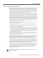
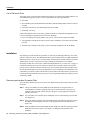
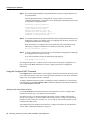
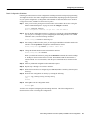
1
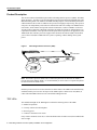
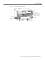
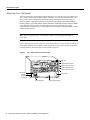
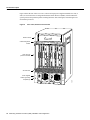
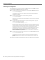
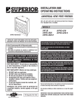
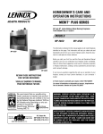
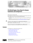
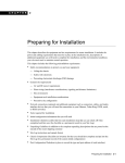
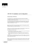
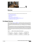
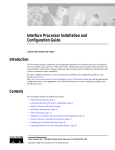
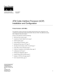
Doc. No. 78-1065-03
Token Ring Interface Processor (TRIP)
Installation and Configuration
Product Numbers: CX-TRIP2 and CX-TRIP4
This document provides instructions for installing the Token Ring interface processor (TRIP) in your
Cisco 7000 and Cisco 7500 series routers. The TRIP provides two or four IEEE 802.5 Token Ring
network interfaces.
The sections in this document include the following:
•
•
•
•
•
•
•
•
Product Description, page 2
Installation Prerequisites, page 11
Installation, page 16
Checking the Installation, page 19
Configuring the Interfaces, page 20
Checking the Configuration, page 24
Upgrading Microcode, page 25
Cisco Information Online, page 28
Before beginning the installation, read this entire document to ensure that you have all the necessary
tools and equipment and that you have the correct modules for your system configuration.
Copyright © 1995
Cisco Systems, Inc.
All rights reserved.
1
Product Description
Product Description
This section contains a detailed description of the Token Ring interface processor (TRIP). The TRIP,
shown in Figure 1, provides two or four Token Ring ports for interconnection with IEEE 802.5 and
IBM Token Ring media. The TRIP uses the IBM 16/4-Mbps chipset with an imbedded performance
enhanced interface driver and 16.7 MHz bit slice processor for high speed processing. The speed on
each port is set independently with a software command for either 4 or 16 Mbps. The TRIP firmware
(microcode), which contains card-specific software instructions, resides in a ROM in socket U41.
You may need to replace this component in the future to enable new features or enhancements (if so,
replacement instructions will be provided with the replacement component in an upgrade kit). The
TRIP and all other interface processors support online insertion and removal (OIR), which allows
you to remove and install a TRIP while the system is operating, without shutting down system
power.
Figure 1
Token Ring Interface Processor (TRIP)
4M
0
1
2
3
16
M
En
bp
ab
s
le
bp
s
d
IN
RI
NG
H2006
U41,
microcode ROM
Note The interface processor metal carrier contains the printed circuit board for the TRIP. To
prevent electrostatic damage (ESD), we recommend that you never remove or separate the printed
circuit board from the metal carrier.
Interface processor slots are accessed from the rear of the chassis. The TRIP can be installed in any
available interface processor slot. Each port on the TRIP requires a media access unit (MAU) to
connect the DE-9TRIP connectors to the external Token Ring networks.
TRIP LEDs
The enabled LED light on the TRIP lights to indicate the following status of the TRIP:
•
•
•
•
Enabled for operation
Correctly connected to the backplane
Receiving power
Contains a valid microcode version
If any of these conditions is not met, or if the initialization fails for other reasons, the Enabled LED
does not light.
2 Token Ring Interface Processor (TRIP) Installation and Configuration
Product Description
When a Token Ring interface is configured by using software commands, three LEDs for each port
indicate the following:
•
•
•
16 Mbps—Lights if the interface is operating at 16 Mbps.
4 Mbps—Lights if the interface is operating at 4 Mbps.
In Ring—When lit, indicates that the interface is currently active and inserted into the ring. When
not lit, the interface is not active and is not inserted into a ring.
Token Ring Connection Equipment
You will need an 802.5 MAU or a multistation access unit (MSAU) to provide the interface between
the TRIP Token Ring interfaces and the external ring, and a Token Ring lobe cable between each
TRIP port and the MAU or MSAU. Lobe cables connect each Token Ring station (TRIP port) to the
MAU or MSAU, and patch cables can connect adjacent MSAUs to form one large ring.
TRIP ports operate at either 4 or 16 Mbps. The default speed for all TRIP ports is 4 Mbps, which
you can change to 16 Mbps on any port using the configuration command ring-speed n, where n is
the speed (4 or 16) in Mbps. The speed of each Token Ring port must match the speed of the ring to
which it is connected. Before you enable the Token Ring interfaces, ensure that each is set for the
correct speed, or it can bring down the ring.
Caution Each TRIP port must be configured for the same ring speed as the ring to which it is
connected, either 4 or 16 Mbps. If the port is set for a different speed, it will cause the ring to beacon,
which effectively brings the ring down and makes it inoperable.
Token Ring Cables and Connectors
The Token Ring ports on the TRIP are DB-9 (PC type) receptacles that require Type 1 or Type 3 lobe
cables. Type 1 lobe cables use shielded twisted pair cable and terminate at the network end with a
large MAU plug. (See Figure 2.) Type 3 lobe cables use either shielded or unshielded twisted pair
(UTP) cable and terminate at the network end with an RJ-11 plug. (See Figure 2.) The TRIP end of
both cable types is a DB-9 plug.
Token Ring Type 1 Lobe Cable Connectors, DB-9 and MAU Types
TRIP end
MSAU or
MAU end
H2056
Figure 2
Token Ring Interface Processor (TRIP) Installation and Configuration
3
Product Description
Figure 3
Token Ring Type 3 Lobe Cable Connectors, DB-9 and RJ-11 Types
MAU end
H2055
TRIP end
Token Ring Physical Connections
The term Token Ring refers to both IBM’s Token Ring Network, which IBM developed in the 1970s,
and to IEEE 802.5 networks. The IEEE 802.5 specification was modeled after, and still closely
shadows, IBM’s network. The two types are compatible, although the specifications differ slightly.
Token Ring and IEEE 802.5 are token passing networks, which move a small frame, called a token,
around the network. Possession of the token grants the right to transmit; a station with information
to transmit must wait until it detects a free token passing by.
The IBM Token Ring specifies a star topology, with all end stations connected through a device
called a multistation access unit (MSAU). IEEE 802.5 does not specify any topology, although most
implementations are based on a star configuration with end stations attached to a device called a
media access unit (MAU). Also, IBM Token Ring specifies twisted-pair cabling, whereas IEEE
802.5 does not specify media type. Most Token Ring networks use shielded twisted-pair cabling;
however, some networks that operate at 4 Mbps use unshielded twisted-pair cable. Table 1 shows a
comparison of the two types.
Table 1
IBM Token Ring and IEEE 802.5 Comparison
Network Type
Data Rates
Stations/ Segment
Topology
Media
Signaling
Access
Method
IBM Token Ring
network
4, 16 Mbps
260 shielded twisted-pair
72 unshielded twisted-pair
Star
Twisted
pair
Baseband
Token passing
Differential
Manchester
IEEE 802.5 network
4, 16 Mbps
250
Not
specified
Not
specified
Baseband
Token passing
Differential
Manchester
4 Token Ring Interface Processor (TRIP) Installation and Configuration
Encoding
Product Description
In the typical Token Ring network shown in Figure 4, lobe cables connect each Token Ring station
(TRIP port) to the MSAU (or MAU), and patch cables connect adjacent MSAUs (or MAUs) to form
one large ring.
Figure 4
Token Ring Network Physical Connections
MAU or MSAU
Ring
in 1
2
3
4
5
6
MAU or MSAU
7
8
Ring
out
Ring
in 1
2
3
Stations
2
3
4
5
5
6
7
8
Ring
out
7
8
Ring
out
Stations
Patch
cables
MAU or MSAU
Ring
in 1
4
6
7
Ring
8 out
MAU or MSAU
Ring
in 1
2
3
4
5
6
Stations
Stations
H2058
Lobe
cables
All TRIP ports support both 4- and 16-Mbps operation and early token release. The default for all
ports is for 4 Mbps operation and early token release disabled. Both states are enabled with
configuration commands in the configuration mode. To enable 16 Mbps, specify the slot/port
address and use the configuration command ring-speed 16; to return to 4 Mbps operation, use the
command ring-speed 4. To enable and disable early token release, specify the slot/port address and
use the configuration command [no] early token release. For complete descriptions and examples
of software commands, refer to the related software configuration documentation.
Token Ring Interface Processor (TRIP) Installation and Configuration
5
Product Description
What is the Cisco 7000 Series?
Network interfaces reside on modular interface processors, which provide a direct connection
between your external network and the high speed Cisco Extended Bus (CxBus) in the Cisco 7000
series routers, and the CyBus in the Cisco 7500 series routers.
Figure 5 and Figure 6 show the rear of the Cisco 7000 series routers: the seven-slot Cisco 7000 and
the five-slot Cisco 7010. Access to the processor slots and the removable power supplies is from the
rear, as shown. Two slots are reserved for the Route Processor (RP), which contains the system
processor, and the Switch Processor (SP) (or Silicon Switch Processor [SSP]), which performs
packet switching functions. The remaining slots support any combination of network interface types:
channel attachment, serial, Ethernet, Fast Ethernet, multichannel interface, Token Ring, Fiber
Distributed Data Interface (FDDI), or High-Speed Serial Interface (HSSI).
Figure 5
Cisco 7000, Interface Processor End
Captive
installation screw
DC
AC
FA
IL
PO
WE
R
Upper
power supply
I
O
Captive
installation screw
DC
AC
FA
IL
PO
WE
H2358
R
Lower
power supply
I
O
Slot 0
6 Token Ring Interface Processor (TRIP) Installation and Configuration
1
2
3
4
SP RP
or
slot
SSP
slot
Product Description
Figure 6
Cisco 7010, Interface Processor End
RP slot
SP or SSP slot
Interface processor slot 2
Interface processor slot 1
Interface processor slot 0
H2359
Power switch
Chassis ground
screw
Power receptacle
DC OK LED
AC-input power supply
Token Ring Interface Processor (TRIP) Installation and Configuration
7
Product Description
What is the Cisco 7500 Series?
The Cisco 7500 series consists of three router models: the Cisco 7505, the Cisco 7507, and the Cisco
7513. All three models provide high reliability, availability, serviceability, and performance. The
three systems support multiprotocol, multimedia routing, and bridging with a wide variety of
protocols and any combination of Ethernet, Fast Ethernet, Token Ring, Fiber Distributed Data
Interface (FDDI), serial, multichannel, channel attachment, and High-Speed Serial Interface (HSSI)
media. Network interfaces reside on modular interface processors, which provide a direct
connection between the high-speed, 1.067-gigabits-per-second (Gbps) Cisco Extended Bus (CyBus)
and the external networks.
Note The Cisco 7507 and Cisco 7513 have dual CyBuses, for an aggregate bandwidth of
2.134 Gpbs.
Figure 7 shows the rear of the five-slot Cisco 7505 router. In the Cisco 7505, one slot (4) is reserved
for the Route Switch Processor (RSP1), which contains the system processor and performs packet
switching functions. Slots 0 through 3 are for interface processors.
Cisco 7505, Interface Processor End
T
E
OL
NS
CO
AU
X.
HA
SE
U
RE
CP
T
EC
Interface processor slot 3
EN
AB
EN
LE
AB
LE
EJ
SL SLO
OT T
0 1
AL
RM
NO
RSP slot
ROUTE SWITCH PROCESSOR
LT
Figure 7
Interface processor slot 2
Interface processor slot 1
Interface processor slot 0
H2761
ower switch
Chassis
grounding
receptacles
Power receptacle
8 Token Ring Interface Processor (TRIP) Installation and Configuration
AC-input power supply
DC OK LED
Product Description
Figure 8 shows the rear of the seven-slot Cisco 7507 router. In the Cisco 7507, up to two slots (2 and
3) are reserved for the Route Switch Processor (RSP2), which contains the system processor and
performs packet switching functions. Slots 0 and 1, and 4 through 6 are for interface processors.
Figure 8
Cisco 7507, Interface Processor End
Captive
nstallation screw
DC
AC
FA
IL
PO
WE
R
EN
NO
AB
RM
LE
AL
Upper
ower supply
Chassis
grounding
eceptacles
EJ
EC
T
SL SLO
OT T
0 1
I
SL MAS
AV T
E ER
O
SL
AV
E/M
AS
TE
R
Captive
nstallation screw
CP
U
HA
LT
EN
AB
RE
LE
SE
T
DC
AC
FA
IL
PO
WE
H3888
R
Lower
ower supply
AU
X.
NS
OL
E
I
ROUTE SWITCH PROCESSOR 2
CO
O
Slot 0
1
2
3
4
5
6
RSP slots
Token Ring Interface Processor (TRIP) Installation and Configuration
9
Product Description
Figure 9 shows the rear of the Cisco 7513, with two AC-input power supplies installed. Two slots (6
and 7) are reserved for the second generation Route Switch Processor (RSP2), which contains the
system processor and performs packet switching functions. Slots 0 through 5, and 8 through 12 are
for interface processors.
Figure 9
Cisco 7513, Interface Processor End
Blower module
Cable-management
bracket
NO
RM
AL
EN
AB
LE
EJE
CT
SLO SLO
T0 T1
SLA MAS
VE TE
R
Card cage and
processor modules
SLA
VE
/M
AS
TE
R
CP
U
HA
LT
RE
SE
EN
T
AB
LE
AU
X.
ROUTE SWITCH PROCESSOR 2
CO
NS
OLE
Air intake vent
Chassis grounding
receptacle (2)
FAN OUTPUT
OK
AC
FAN OUTPUT
OK
OK
FAIL
FAIL
POWER
A
POWER
I
I
0
0
10 Token Ring Interface Processor (TRIP) Installation and Configuration
B
H3087
Power supplies
AC
OK
Installation Prerequisites
Installation Prerequisites
This section provides a list of parts and tools you will need to perform the installation, and safety
and ESD-prevention guidelines to help you to avoid injury and damage to the equipment. It also
provides a detailed description of the online insertion and removal (OIR) function to help you
perform online installation successfully and avoid error message and system restarts. If you are
installing a new TRIP, be sure to review the equipment descriptions and distance limitations in the
section “Distance Limitations for Token Ring Connections” on page 11 when preparing your site
and planning network connections.
Distance Limitations for Token Ring Connections
The maximum transmission distance is not defined for IEEE 802.5 (Token Ring) networks. Shielded
twisted-0pair cabling is most commonly used for rates of 4 and 16 Mbps. Twisted pair cabling is
more susceptible to interference than other types of cabling; therefore, the network length and
repeater spacing should be planned accordingly.
Ring Speed Considerations
Before you install the TRIP, determine the ring speed (4 or 16 Mbps) of each ring to be connected
to the server. There is no factory default for the interface speed; you must set the speed of each
interface (within the setup command facility or with the ring-speed command) before you bring the
interface up and insert it into the ring with the no shutdown command.
If an interface has an undefined or incorrect ring speed and is not shut down, the ring will beacon.
This effectively takes the ring down and makes it inoperable.
Safety
Following are safety guidelines that you should follow when working with any equipment that
connects to electrical power or telephone wiring.
Electrical Equipment Safety
Follow these basic guidelines when working with any electrical equipment:
•
Before beginning any procedures requiring access to the chassis interior, locate the emergency
power off switch for the room in which you are working.
•
•
•
•
Disconnect all power and external cables before moving a chassis.
•
Carefully examine your work area for possible hazards such as moist floors, ungrounded power
extension cables, and missing safety grounds.
Do not work alone when potentially hazardous conditions exist.
Never assume that power has been disconnected from a circuit; always check.
Do not perform any action that creates a potential hazard to people or makes the equipment
unsafe.
Token Ring Interface Processor (TRIP) Installation and Configuration
11
Installation Prerequisites
Telephone Wiring Safety
Use the following guidelines when working with any equipment that is connected to telephone
wiring or to other network cabling:
•
•
Never install telephone wiring during a lightning storm.
•
Never touch uninsulated telephone wires or terminals unless the telephone line has been
disconnected at the network interface.
•
Use caution when installing or modifying telephone lines.
Never install telephone jacks in wet locations unless the jack is specifically designed for wet
locations.
Preventing Electrostatic Discharge (ESD) Damage
Electrostatic discharge (ESD) damage, which can occur when electronic cards or components are
improperly handled, results in complete or intermittent failures. The TRIP comprises a printed
circuit board that is fixed in a metal carrier. Electromagnetic interference (EMI) shielding,
connectors, and a handle are integral components of the carrier. Although the metal carrier helps to
protect the board from ESD, use a preventive antistatic strap whenever handling the TRIP. Handle
the carriers by the handles and the carrier edges only; never touch the boards or connector pins.
Following are guidelines for preventing ESD damage:
•
•
Always use an ESD wrist or ankle strap and ensure that it makes good skin contact.
•
When installing a TRIP, use the ejector levers to properly seat the bus connectors in the
backplane, then tighten both captive installation screws. (See Figure 10.) These screws prevent
accidental removal, provide proper grounding for the system, and they help to ensure that the bus
connectors are seated in the backplane.
•
When removing a TRIP, use the ejectors to release the bus connectors from the backplane. Use
the handle to pull the TRIP out slowly while keeping your other hand underneath the carrier to
guide it straight out of the slot.
•
•
Handle carriers by the handles and carrier edges only; avoid touching the board or connectors.
•
Avoid contact between the TRIP and clothing. The wrist strap only protects the board from ESD
voltages on the body; ESD voltages on clothing can still cause damage.
•
Never attempt to remove the TRIP printed circuit board from the metal interface processor
carrier.
Connect the equipment end of the strap to a captive installation screw on an installed power
supply.
Place a removed TRIP board-side-up on an antistatic surface or in a static shielding bag. If you
plan to return the component to the factory, immediately place it in a static shielding bag.
Periodically check the resistance value of the antistatic strap. The measurement should
be between 1 and 10 megohms.
Caution
12 Token Ring Interface Processor (TRIP) Installation and Configuration
Installation Prerequisites
Online Insertion and Removal—An Overview
Online insertion and removal (OIR) allows you to remove and replace interface processors while the
system is operating; you do not need to notify the software or shut down the system power. This
section describes the mechanical functions of the system components and stresses the importance of
following the correct procedures to avoid unnecessary restarts or card failures. This section is for
background information only. Subsequent sections provide specific procedures for removing and
installing a TRIP. All CxBus and CyBus interface processors support OIR
Each processor module contains a bus connector with which it connects to the system backplane.
The bus connector is a set of tiered pins, in three lengths. The pins send specific signals to the system
as they make contact with the backplane. The system assesses the signals it receives and the order
in which it receives them to determine what event is occurring and what task it needs to perform,
such as reinitializing new interfaces or shutting down removed ones. For example, when you insert
an interface processor, the longest pins make contact with the backplane first, and the shortest pins
make contact last. The system recognizes the signals and the sequence in which it receives them. The
system expects to receive signals from the individual pins in this logical sequence, and the ejector
levers help to ensure that the pins mate in this sequence.
When you remove or insert an interface processor, the backplane pins send signals to notify the
system, which then performs as follows:
1 Rapidly scans the backplane for configuration changes and does not reset any interfaces.
2 Initializes all newly inserted interface processors, noting any removed interfaces and placing
them in the administratively shutdown state.
3 Brings all previously configured interfaces on the interface processor back to the state they were
in when they were removed. Any newly inserted interfaces are put in the administratively shut
down state, as if they were present (but unconfigured) at boot time. If a similar interface processor
type has been reinserted into a slot, then its ports are configured and brought online up to the port
count of the original interface processor.
OIR functionality enables you to add, remove, or replace interface processors with the system
online, which provides a method that is seamless to end users on the network, maintains all routing
information, and ensures session preservation.
When you insert a new interface processor, the system runs a diagnostic test on the new interfaces
and compares them to the existing configuration. If this initial diagnostic test fails, the system
remains off line for another 15 seconds while it performs a second set of diagnostic tests to
determine whether or not the interface processor is faulty and if normal system operation is possible.
If the second diagnostic test passes, which indicates that the system is operating normally and the
new interface processor is faulty, the system resumes normal operation but leaves the new interfaces
disabled. If the second diagnostic test fails, the system crashes, which usually indicates that the new
interface processor has created a problem on the bus and should be removed.
The system brings online only interfaces that match the current configuration and were previously
configured as up; all other interfaces require that you configure them with the configure command.
On interface processors with multiple interfaces, only the interfaces that have already been
configured are brought online. The new interface remains in the administratively shutdown state
until you configure it and bring it online.
Caution While the TRIP supports OIR, the system may indicate a hardware failure if you fail to
follow proper procedures.
Token Ring Interface Processor (TRIP) Installation and Configuration
13
Installation Prerequisites
The function of the ejector levers (see Figure 10) is to align and seat the card connectors in the
backplane. Failure to use the ejectors and insert the interface processor properly can disrupt the order
in which the pins make contact with the backplane. Follow the TRIP installation and removal
instructions carefully, and review the following examples of incorrect insertion practices and results:
•
Using the handle to force the interface processor all the way into the slot can pop the ejectors out
of their springs. If you then try to use the ejectors to seat the interface processor, the first layer of
pins (which are already mated to the backplane) can disconnect and then remate with the
backplane, which the system interprets as a board failure.
•
Using the handle to force or slam the interface processor all the way into the slot can also damage
the pins on the board connectors if they are not aligned properly with the backplane.
•
When using the handle (rather than the ejectors) to seat the interface processor in the backplane,
you may need to pull the interface processor back out and push it in again to align it properly.
Even if the connector pins are not damaged, the pins mating with and disconnecting from the
backplane will cause the system to interpret a board failure. Using the ejectors ensures that the
board connector mates with the backplane in one continuous movement.
•
Using the handle to insert or remove an interface processor, or failing to push the ejectors to the
full 90-degree position, can leave some (not all) of the connector pins mated to the backplane, a
state which will hang the system. Using the ejectors and making sure that they are pushed fully
into position ensures that all three layers of pins are mated with (or free from) the backplane.
It is also important to use the ejector levers when removing an interface processor to ensure that the
board connector pins disconnect from the backplane in the logical sequence expected by the system.
Any RP, SP, or interface processor that is only partially connected to the backplane can hang the bus.
Detailed steps for correctly performing OIR are included with the following procedures for
installing and removing a TRIP.
14 Token Ring Interface Processor (TRIP) Installation and Configuration
Installation Prerequisites
Ejector Levers and Captive Installation Screws
Interface processor
card slot
Ejector
lever
Interface processor card
carrier guide (black)
a
b
Captive
installation
screw
c
H1984
Figure 10
Token Ring Interface Processor (TRIP) Installation and Configuration
15
Installation
List of Parts and Tools
Verify that you have all of the parts and optional equipment you will need to install the TRIP. If you
need additional equipment, contact a service representative for ordering information.
•
•
One TRIP
•
•
9-pin male connector for each Token Ring connector on TRIP
One Token Ring 802.5 media attachment unit (MAU) and Token Ring adapter cable for each port
on TRIP
Grounding wrist strap
A disposable ESD-prevention wrist strap is included with all new components and upgrade kits; use
it to prevent damage to equipment from electrostatic discharge.
•
•
If you are replacing the existing TRIP in your system, you also need a replacement TRIP.
•
Antistatic mat or antistatic foam (only if you are replacing components such as the ROM)
A large Phillips or flat-blade screwdriver for the captive installation screws that secure the TRIP
in its slot.
Installation
The following sections describe the procedures for removing or installing a TRIP in a Cisco 7000
and Cisco 7500 series router. The OIR function allows you to install and remove a TRIP without first
shutting down the system; however, you must follow the instructions carefully. Failure to insert the
TRIP properly can cause system error messages indicating a board failure. For a complete
description of OIR, refer to the section “Online Insertion and Removal—An Overview” on page 13.
Each unused interface processor slot contains an interface processor filler (which is an interface
processor carrier without an interface board) to keep dust out of the chassis and to maintain proper
air flow through the interface processor compartment. If you are installing a new TRIP that is not a
replacement, you must first remove the interface processor filler from an unused slot, proceed to the
section “Removing an Interface Processor Filler.” If you are replacing a TRIP, proceed to the section
“Removing a TRIP.”
Removing an Interface Processor Filler
Select an unused interface processor slot for the new TRIP and remove the interface processor filler
as follows:
Step 1 Choose an available slot for the TRIP and ensure that there is enough clearance to
accommodate any interface equipment that you will connect directly to the ports (for
example, transceivers that connect directly to the ports overlap equipment on adjacent
interface processors).
Step 1 Use a screwdriver to loosen the captive installation screws on the interface processor filler.
(See Figure 10.)
Step 2 Place your thumbs on both ejectors and simultaneously pull them both outward to release
the TRIP from the backplane connector (in the opposite direction from that shown in
Figure 10c).
Step 3 Grasp the handle with one hand and pull the filler straight out of the slot, keeping your other
hand under the carrier to guide it. (See Figure 11.) Keep the carrier parallel to the
backplane.
16 Token Ring Interface Processor (TRIP) Installation and Configuration
Installation
Step 4 Store the interface processor filler for future use.
To help prevent dust and contaminants from entering the chassis, do not leave the interface processor
slot open. Immediately proceed to the section “Installing a TRIP” on page 18.
Removing a TRIP
The TRIP supports OIR; therefore, you need not shut down the interface or the system power when
removing a TRIP. If you are replacing a failed TRIP, remove the existing board first, then replace the
new TRIP in the same slot.
Figure 11 shows proper handling of an interface processor for installation in the Cisco 7010 and
Cisco 7505 models. The processor slots are oriented horizontally in the Cisco 7010 and Cisco 7505,
and vertically in the Cisco 7000, Cisco 7507, and Cisco 7513.
To remove a TRIP, follow these steps:
Step 1 Disconnect the all cables from the TRIP ports (if you are moving the TRIP to another port,
this step is not necessary).
Step 2 Use a screwdriver to loosen the captive installation screws at both ends of the TRIP.
(See Figure 10.)
Caution Always use the ejector levers to remove or install the TRIP. Failure to do so can cause
erroneous system error messages indicating a board failure.
Handling an Interface Processor During Installation and Removal
H1985
Figure 11
Captive installation
screws
Step 3 Place your thumbs on the ejector levers and simultaneously pull both of the ejectors
outward (in the opposite direction from that show in Figure 10c) to release the TRIP from
the backplane connector.
Step 4 Use the handle to carefully pull the TRIP straight out of the slot, keeping your other hand
under the carrier to guide it. (See Figure 11.) Keep the TRIP parallel to the backplane.
Token Ring Interface Processor (TRIP) Installation and Configuration
17
Installation
Step 5 Place the removed TRIP on an antistatic mat or foam pad, or place it in an antistatic bag if
you will return it to the factory.
Step 6 If the interface processor slot is to remain empty, install an interface processor filler
(MAS7K-BLANK) to keep dust out of the chassis and to maintain proper air flow through
the interface processor compartment.
To help prevent dust and contaminants from entering the chassis, do not leave the interface processor
slot open. Immediately proceed to the section “Installing a TRIP” on page 18.
Installing a TRIP
The TRIP slides into the open interface processor slot and directly to the backplane. The interface
processors are keyed to guide pins on the backplane, so the TRIP can be installed only in an interface
processor slot. (See Figure 5, Figure 6, Figure 7, Figure 8, or Figure 9, depending on your chassis.)
Figure 10 shows the functional details of inserting an interface processor and using the ejectors.
Figure 11 shows proper handling of an interface processor during installation.
Caution Remove or insert only one interface processor at a time. Allow at least 15 seconds for the
system to complete its discovery and initialization tasks before removing or inserting another
interface processor. Disrupting the sequence before the system has completed it verification can
cause the system to interpret hardware failures.
The TRIP supports ring speeds of 4 and 16 Mbps. Follow these steps to install a TRIP:
Step 1 Ensure the console terminal is connected to the RP (or RSP) Console port and that the
console is turned ON.
Step 2 Hold the TRIP handle with one hand, and place your other hand under the carrier to support
the TRIP and guide it into the slot. (See Figure 11.) Avoid touching the card or any
connector pins.
Caution To prevent ESD damage, handle interface processors by the handles and carrier edges
only.
Step 3 Place the back of the TRIP in the slot and align the notch on the carrier with the groove in
the slot. (See Figure 10.)
Step 4 While keeping the TRIP parallel to the backplane, carefully slide it into the slot until the
back of the faceplate makes contact with the ejector levers, then stop. (See Figure 10b.)
Caution Always use the ejector levers when installing or removing processor modules. A module
that is partially seated in the backplane will cause the system to hang and subsequently crash, and
shoving or slamming the interface processor into the slot can damage the backplane and connector
pins.
Step 5 Using your thumbs, simultaneously push both ejectors inward until the TRIP is pushed
entirely into its slot. (See Figure 10c.)
Step 6 Tighten both of the captive installation screws.
18 Token Ring Interface Processor (TRIP) Installation and Configuration
Checking the Installation
Step 7 Attach network interface cables or other connection equipment to the interface ports.
(See Figure 12).
Figure 12
Token Ring Connections
H1383a
TRIP
MAU
Step 8 Check the status of the interfaces as follows:
•
If this installation was a replacement TRIP, use the show interfaces or show controller
[type] command to verify that the system has acknowledged the new interfaces and
brought them up.
•
If the interfaces are new, use the configure command or the setup command facility to
configure the new interface(s) (this does not have to be done immediately, but the
interfaces will not be available until you configure them).
Checking the Installation
The TRIP contains one enabled LED and a row of three LEDs for each Token Ring interface.
(See Figure 11). The row of three LEDs indicate the speed (4 or 16 Mbps) of the interface and
whether the interface is inserted in the ring.
When you install the TRIP in an interface processor slot and turn ON the power (if the power was
turned off), the following events occur:
•
The enabled LED lights to indicate that the TRIP is operational and that it is powered up. It does
not mean that the interface ports are functional or enabled. An error condition exists if the TRIP’s
enabled LED is not lit after power up or after initialization. If this happens, check that the TRIP
is installed correctly. If a second power up attempt also fails, contact a customer service
representative.
•
The horizontal set of LEDs flash for about four or five seconds and are then turned off. These
LEDs are turned on again after you configure each Token Ring interface as described in the
section “Configuring the Interfaces” on page 20.
Token Ring Interface Processor (TRIP) Installation and Configuration
19
Configuring the Interfaces
4
IN
Mb Mbp RIN
ps
s
G
TRIP LEDs
H2065
2
3
0
1
16
EN
A
BL
ED
Figure 13
Configuring the Interfaces
You can modify the startup configuration for Cisco 7000 series and Cisco 7500 series routers
through the software command interpreter called EXEC. To configure the interfaces for interface
processors, you can use either one of the following EXEC commands:
setup
configure
The setup command facility can be used after first time startup to make basic changes at any time.
The changes you make will affect only the changed elements’ current memory values that are stored
in nonvolatile memory.
The privileged EXEC command configure enables you to perform advanced configurations such as
specifying interfaces.
The EXEC interprets the commands you enter and carries out the corresponding operations. You can
list available EXEC commands by entering a question mark (?). You also can enter a question mark
to obtain more information about commands. For example, enter terminal ? to obtain a list of
terminal commands or show ? to obtain a list of show commands.
Using the EXEC Command Interpreter
Before you use the setup or the configure command, you must have privileged access to the EXEC
command interpreter. The system prompt for the privileged level ends with a pound sign (#) instead
of an angle bracket (>).
The EXEC enable command allows access to the privileged level, prompting for a password if one
has been set with the enable-password configuration command.
Follow these steps to enter the privileged level of the EXEC.
Step 1 At the EXEC prompt for a router, enter the enable command:
Router> enable
The EXEC prompts you for a privileged level password:
Password:
Step 2 Enter the password.
For security purposes, the password is not displayed. (Also note that the password is case
sensitive). When you enter the correct password, the system displays the privileged mode
system prompt:
Router#
20 Token Ring Interface Processor (TRIP) Installation and Configuration
Configuring the Interfaces
To configure Token Ring interfaces using the setup EXEC command facility, follow the instructions
in the section “Using the Setup Command” on page 21. To configure the Token Ring interfaces by
using the configure EXEC command, follow the instructions in the section “Using the Configure
EXEC Command” on page 22.
Using the Setup Command
The setup command facility identifies all interfaces (including the Token Ring interfaces for the
ports on the TRIP) that are installed and prompts you for configuration information for each installed
interface. When you finish configuring one interface, the setup command facility prompts you for
the next, continuing until each interface has been configured.
When you enter the setup command facility after first time startup, you must run through the entire
dialog until you come to the interface you want to change. Note that when you use the setup
command after first time startup, the default values indicated within the brackets in the System
Configuration Dialog are the values last set using the setup command facility or left as defaults.
After you choose to continue with the setup command (by answering yes to the system configuration
dialog prompt), the remainder of the script is the actual configuration process. The dialog prompts
you first for global system parameters, then for configuration information for each interface. The
existing configuration is displayed as the default, in brackets ([ ]), at the end of each prompt. Press
Return to accept the default settings.
Note After you start the setup command facility, the system runs through the entire configuration
process; you cannot quit out of it. To make a change or correct a mistake, press the Return key at
each prompt, answer no when asked if you want to save the configuration, and restart the setup
facility.
Step 1 After you access the privileged level of the EXEC, as described in the section “Using the
EXEC Command Interpreter” on page 20, enter the setup command to begin the setup
facility:
Router# setup
Step 1 The following script is displayed on the screen, with the name of your router as the default
in the brackets.
-System Configuration DialogAt any point you may enter a question mark ‘?’ for help.
Refer to the ‘Getting Started’ Guide for additional help.
Default settings are in square brackets ‘[]’.
Continue with configuration dialog? [yes]:
(Use Ctrl-c to abort configuration at any prompt)
Configuring global parameters:
Enter host name [Router]: sandbox
Step 2 To accept the default and keep the router name, press Return. (If you do want to change
the name of the router, enter the new name before pressing Return.)
Token Ring Interface Processor (TRIP) Installation and Configuration
21
Configuring the Interfaces
Step 3 Proceed through the remainder of the global parameter prompts, using the Return key to
accept the defaults.
After the global parameters are configured, the system prompts you for interface
configuration information, one interface at a time. Following is a partial display of the script
for a previously configured interface:
Configuring interface parameters:
Configuring interface Token Ring0:
Is this interface in use [yes]:
Tokenring ring speed (4 or 16) [16]
Configure IP on this interface? [yes]:
IP address for this interface: 131.108.6.67
(remainder of display text omitted)
Step 4 To accept the default at each prompt and retain the existing configuration information, press
the Return key. When you reach the scripts for configuring new interfaces, enter the new
configuration information at each prompt.
When all interfaces are configured, the system displays the entire configuration script
followed by a prompt for which there is no default (you must enter yes or no):
Use this configuration [yes/no]:
Step 5 To use the configuration you created, enter yes. To discard the configuration file and begin
the configuration process again, enter no.
If you entered yes at the prompt, the following message displays:
Press RETURN to get started!
The configuration process is complete. Proceed to the section “Checking the Configuration” on
page 24. It provides show commands you can use to display and verify the configuration
information.
Using the Configure EXEC Command
The configure EXEC command allows you to configure the interfaces for interface processors in the
Cisco 7000 series and Cisco 7500 series. At the privileged command level, enter the ? command to
display a list of privileged level EXEC commands.
To display information about the interface, including the software and hardware versions and the
controller status, use the show controller cxbus command. To display statistics about the interfaces,
use the show interfaces command.
Identifying Slot and Interface Numbers
Use the show interfaces command to determine which interfaces you need to configure and to
determine the interface type, slot numbers, and port numbers.
The number of ports you configure depends on the number of ports available on the interface
processor. For example, if you install a TRIP with four ports in slot 0, configure the Token Ring
interface for each of these ports as follows: 0/1, 0/2, 03/ and 0/4. The maximum number of ports
available on the TRIP is four.
After identifying the port numbers for the interfaces, configure the interfaces as described in the
section “Basic Configuration Guidelines” on page 23.
22 Token Ring Interface Processor (TRIP) Installation and Configuration
Configuring the Interfaces
Basic Configuration Guidelines
Following are instructions for a basic configuration: enabling an interface and specifying IP routing.
You might also need to enter other configuration subcommands, depending upon the requirements
for your system configuration. (Configuration subcommands are described in the Router Products
Configuration Guide, available on UniverCD or in print.)
Step 1 After you access the privileged level of the EXEC as described in the section “Using the
EXEC Command Interpreter” on page 20, enter the configure command:
Router# configure terminal
Enter configuration commands, one per line.
End with CNTL/Z.
Step 2 Specify the first Token Ring interface to configure by entering the subcommand interface
type slot/port. For example, if you are configuring the Token Ring interface 0 for a TRIP
installed in slot 4, enter the following command:
Router(config)# interface tokenring 4/0
Step 3 If IP routing is enabled on the system, you can assign an IP address and subnet mask to the
interface with the ip address configuration subcommand as follows:
Router(config-int)# ip address ip address subnet mask
Step 4 Change the default shutdown state and enable the interface:
Router(config-int)# no shutdown
When you enable the interface by using the no shutdown command, the LED for 4 Mbps
or 16 Mbps is turned on after about 5 seconds. The IN RING LED for that interface is
turned on about 5 to 18 seconds later, when the port is initialized and is connected to the
ring.
Step 5 Enter any additional configuration subcommands required.
Step 6 Repeat steps 2 through 5 for each new interface.
Step 7 When all new interfaces are configured, press Ctrl-Z (hold the Control key down and press
the Z key).
Step 8 Write the new configuration to memory by entering the following:
Router# copy running-config startup-config
[OK]
Router#
Step 9 Enter quit to exit the configuration mode:
Router# quit
You have now completed configuring the Token Ring interfaces. Check the configuration as
described in the section “Checking the Configuration.”
Token Ring Interface Processor (TRIP) Installation and Configuration
23
Checking the Configuration
Checking the Configuration
After configuring the new interface(s) using either the setup command or the configure command,
use the EXEC show commands to display status information.
Step 1 To display the current system configuration file, enter the show configuration command:
Router# show configuration
The configuration file for the router is displayed. Check the Token Ring configuration
information in the display.
Step 2 To display and check all interfaces, enter the following command:
Router# show interfaces
Each interface is listed along with its assigned IP address. Verify that each new Token Ring
interface appears.
Step 3 To obtain detailed status information about a specific Token Ring interface, specify the
interface with the following command:
Router# show interface tokenring slot/port
Detailed information about the interface is displayed. The first line of display specifies the
interface along with its slot and port number. It indicates whether the hardware is functional
and if the line protocol is up or down. If the line protocol is down (and you did not
administratively shut it down), or if the hardware is not functioning properly, ensure that
the network interface is properly connected and terminated. For explanations of the
displayed information, refer to the Router Products Command Reference and the Router
Products Command Summary publications.
Step 4 To display the current internal status of the processors, use the show controller command:
Router# show controllers token
The display lists the interfaces connected to each processor and indicates whether the
system has identified your new interface. It does not indicate the state of the line or the
protocol.
This completes the installation and configuration procedure for the TRIP and associated equipment.
24 Token Ring Interface Processor (TRIP) Installation and Configuration
Upgrading Microcode
Upgrading Microcode
Depending on how it is configured, the Cisco 7000 series router allows the Switch Processor (SP)
and interface processors to use updated microcode that is available either in Flash memory on the
Route Processor (RP) or on the onboard ROM for each processor. The Cisco 75000 series routers
allow the interface processors to use updated microcode that is available either in Flash memory on
the Route Switch Processor (RSP) or on the onboard ROM for each processor.
The router supports downloadable microcode, which enables you to upgrade microcode versions
without having to physically replace the ROMs on the boards. You can download new microcode
versions, store multiple versions in Flash memory, and boot from them, just as you can with the
system software images. System software upgrades can also contain upgraded microcode images,
which will load automatically when the new software image is loaded.
With downloadable microcode, you should never need to replace the microcode ROM on the board.
If, however, replacement is necessary in the future, specific instructions will also be provided with
the replacement component in an upgrade kit.
Downloading Microcode to Flash Memory
You can download microcode to Flash memory by copying the TFTP image of a microcode version
to Flash memory. When the microcode version is available in Flash memory, you can boot the router
either automatically or manually from Flash memory. Follow these steps to copy a microcode
version from the TFTP server to Flash memory:
Step 1 To display the total amount of Flash memory present, its location, any files that currently
might exist in Flash memory and their size, and the amount of Flash memory remaining,
use the show flash command.
The following type of output is displayed:
4096K bytes of flash memory on embedded flash (in RP1).
file offset
length
name
0
0x40
53330
trip1-0
1
0xD0D4
51432
sp1-0
[4089412/4194304 bytes free]
Note Before you copy a file to Flash memory, be sure there is ample space available in Flash
memory. Compare the size of the file you want to copy to the amount of available Flash memory
shown. If the space available is less than the space required by the file you want to copy, the copy
process will continue, but the entire fill will not be copied into Flash.
Step 2 After you verify that there is sufficient space available in Flash memory for new images,
enter the following command:
Router# copy tftp flash
Step 3 Enter the IP address of the remote host:
IP address or name of remote host [255.255.255.255]? ip address
Step 4 Enter the name of the file you want to copy to Flash:
Name of file to copy ? file name
The format of the file name is the name of the interface processor followed by the version
number (for example, trip1-0).
Token Ring Interface Processor (TRIP) Installation and Configuration
25
Upgrading Microcode
Step 5 Confirm that you want the file copied into Flash:
Copy trip1-0 from 131.108.13.111 into flash memory?
[confirm] yes
Step 6 If you do not want the other microcode files in Flash memory erased, enter no
OR
If you want Flash erased, enter yes.
Erase flash before writing? [confirm] no
If you answered yes, the Flash memory is erased, and the TRIP microcode is copied to
Flash memory. Output similar to the following is displayed:
Zeroing bank...zzzzzzzzzzzzzzzz
Verify zeroed...vvvvvvvvvvvvvvvv
Erasing bank...eeeeeeeeeeeeeeee
Loading from 131.108.1.111: !!!!!!!!!!!!!!!!!!!!!!!!!!!!!!!!!!!!!!!!!!!!!!!!!!!!
[OK - 1906676/4194240 bytes]
Verifying via checksum...
Flash verification successful. Length = 1906676, checksum = 0x12AD
If you answered no, the TRIP microcode is copied to Flash memory without any erasure of
existing files in Flash.
Step 7 Verify that the microcode has been copied to Flash memory:
Router# show flash
The following type of output is displayed:
4096K bytes of flash memory on embedded flash (in RP1).
file
offset
length
name
0
0x40
53330
trip1-0
1
0xD0D4 51432
sp140-34
[4089412/4194304 bytes free]
Step 8 If you want the TRIP to use the microcode in Flash memory immediately, enter the
following commands at the router prompt:
Router# microcode trip flash microcode file name
Router# microcode reload
The microcode reload command immediately enables the TRIP to use the specified
microcode file.
Step 9 To ensure that the new microcode is used by the TRIP after a system reboot, add the
microcode commands to the configuration file. To access the configuration file, enter the
following command:
Router# configure terminal
Step 10 Add the following commands to the configuration file:
microcode trip flash microcode file name
microcode reload
Step 11 To exit the configuration mode, press Ctrl-Z.
Step 12 To write the updated configuration file to the NVRAM, enter the following command:
Router# copy running-config startup-config
26 Token Ring Interface Processor (TRIP) Installation and Configuration
Upgrading Microcode
Step 13 Verify that the correct microcode version is available in Flash memory:
Router# show controllers token
You have now completed downloading microcode to the Flash memory, downloaded the microcode
to the TRIP, added the microcode commands to the configuration file, and updated the NVRAM with
the new configuration file.
If any of the interfaces fail to return to their previous state, refer to the troubleshooting procedures
in the hardware installation and maintenance publication appropriate to your chassis model.
Token Ring Interface Processor (TRIP) Installation and Configuration
27
Cisco Information Online
Cisco Information Online
Cisco Information Online (CIO) is Cisco Systems’ primary, real-time support channel. Maintenance
customers and partners can self-register on CIO to obtain additional content and services.
Available 24 hours a day, 7 days a week, CIO provides a wealth of standard and value-added services
to Cisco’s customers and business partners. CIO services include product information, software
updates, release notes, technical tips, the Bug Navigator, configuration notes, brochures,
descriptions of service offerings, and download access to public and authorized files.
CIO serves a wide variety of users through two interfaces that are updated and enhanced
simultaneously—a character-based version and a multimedia version that resides on the World Wide
Web (WWW). The character-based CIO (called “CIO Classic”) supports Zmodem, Kermit,
Xmodem, FTP, Internet e-mail, and fax download options, and is excellent for quick access to
information over lower bandwidths. The WWW version of CIO provides richly formatted
documents with photographs, figures, graphics, and video, as well as hyperlinks to related
information.
You can access CIO in the following ways:
•
•
•
WWW:
Telnet:
http://www.cisco.com.
cio.cisco.com.
Modem: From North America, 408 526-8070; from Europe, 33 1 64 46 40 82. Use the
following terminal settings: VT100 emulation; databits: 8; parity: none; stop bits: 1; and baud
rates up to 14.4 kbps.
For a copy of CIO’s Frequently Asked Questions (FAQ), contact
additional information, contact [email protected].
[email protected].
For
Note If you are a network administrator and need personal technical assistance with a Cisco
product that is under warranty or covered by a maintenance contract, contact Cisco’s Technical
Assistance Center (TAC) at 800 553-2447, 408 526-7209, or [email protected]. To obtain general
information about Cisco Systems, Cisco products, or upgrades, contact 800 553-6387,
408 526-7208, or [email protected].
This document is to be used in conjunction with the Cisco 7000 Hardware Installation and Maintenance, Cisco 7010 Hardware Installation and Maintenance, Cisco 7505 Hardware
Installation and Maintenance, Cisco 7507 Hardware Installation and Maintenance, and Cisco 7513 Hardware Installation and Maintenance publications. (1062trip.fm)
Catalyst, CD-PAC, CiscoFusion, Cisco IOS, CiscoPro, CiscoView, CiscoVision, CiscoWorks, ControlStream, DesignDirector, EtherChannel, HubDirector, HubSwitch, LAN2LAN,
LAN2LAN Enterprise, LAN2LAN Remote Office, LAN2PC, Newport Systems Solutions, Packet, PC2LAN/X.25, Point and Click Internetworking, RouteStream, SMARTnet,
SwitchProbe, SynchroniCD, The Cell, TrafficDirector, VirtualStream, VlanDirector, WNIC, Workgroup Director, Workgroup Stack, and XCI are trademarks, Access by Cisco and
Bringing the power of internetworking to everyone are service marks, and Cisco, Cisco Systems, the Cisco Systems logo, EtherSwitch, IGRP, Kalpana, LightStream, and UniverCD are
registered trademarks of Cisco Systems, Inc. All other trademarks, service marks, registered trademarks, or registered service marks mentioned in this document are the property of their
respective owners.
Copyright © 1995, Cisco Systems, Inc.
All rights reserved. Printed in USA
959R
28 Token Ring Interface Processor (TRIP) Installation and Configuration