1
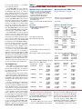
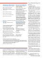
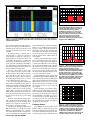
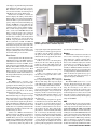
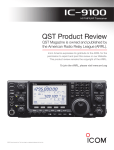
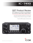
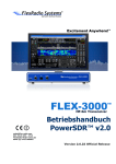
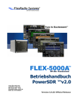
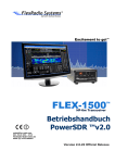
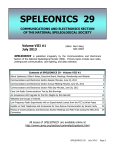
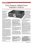
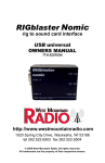
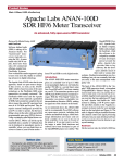
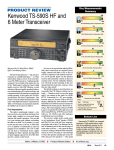
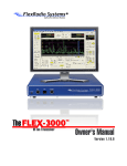
QST 10/ 2009 www.rv3apm.com/rxdx.html Product Review and Short Takes from QST Magazine October 2009 Product Reviews: FlexRadio Systems FLEX-3000 Software Defined HF/50 MHz Transceiver Short Takes: West Mountain Radio’s RIGblaster duo Copyright © 2009 by the American Radio Relay League Inc. All rights reserved. Key Measurements Summary product review FlexRadio Systems FLEX-3000 Software Defined HF/50 MHz Transceiver 111* 112* 20 70 140 20 kHz Blocking Gain Compression (dB) 111* 112* 70 2 140 2 kHz Blocking Gain Compression (dB) 101 , 97 20 50 110 20 kHz 3rd-Order Dynamic Range (dB) , 95 50 2 110 2 kHz 3rd-Order Dynamic Range (dB) 29 , Reviewed by Steve Sant Andrea, AG1YK Assistant Editor The FLEX-3000 is a software defined r adio (SDR) that uses a minimum of hardware/ analog components to produce a working HF/50 MHz, 100 W all mode transceiver. As with previous FlexRadio offerings, the radio is only a third of the actual system. It must be combined with a computer and software. The computer is a significant factor in the purchase of a FLEX-3000, as the quality of the computer greatly affects the overall system performance. When considering the FLEX-3000, check FlexRadio’s Web site for information on computer requirements. For this review, the ARRL purchased a Dell Inspiron 530 running an Intel Core 2 Quad CPU at 2.83 GHz with 3 GB of RAM memory. The operating system is Windows Vista 6.0.6001 SP1. An IEEE 1394 (FireWire) 400 MB/s interface connects the computer to the radio. The software, FlexRadio Systems Power SDR, is freely downloadable from FlexRadio’s Web site. This is the same software used with other FlexRadio transceivers we’ve reviewed. It’s regularly updated to improve performance and add features — one of the big attractions of an SDR. Sibling Rivalry The FLEX-3000 is the little brother of the FLEX-5000, which QST reviewed last year.1 The ’3000 has been designed as an entry-level SDR for those who are curious about how these radios actually “play” but may not want to spend the additional $1000 or so for the advanced capabilities of the FLEX-5000. It’s also smaller and easier to 28 +35 20 -40 20 kHz 3rd-Order Intercept (dBm) , 26 +35 -40 2 2 kHz 3rd-Order Intercept (dBm) , TX -20 -30 Transmit 3rd-Order IMD (dB) , -45 TX -20 PR040 Lindquist, WW3DE, “FlexRadio Systems FLEX-5000A HF/50 MHz Transceiver,” QST, Jul 2008, pp 39-45. QST Product Reviews are available on the Web at www.arrl.org/ members-only/prodrev/. -70 Transmit 9th-order IMD (dB) 80 M Key: 1R. -35 Dynamic range and intercept values with preamp off. Intercept values were determined using -97 dBm reference 20 M * Blocking level exceeds the threshold of ADC clipping. Bottom Line The FLEX-3000 is a compact software defined radio (SDR) in the mid-range price class. It can be used at home or paired with a notebook computer for operation on the go. Although it gives up some features compared to the FLEX-5000A, it doesn’t give up much performance. Figure 1 — Rear panel connections are straightforward — dc power, antenna, computer, amplified speakers, TR and amplifier switching and FlexWire I/O for accessories. Mark J. Wilson, K1RO Product Review Editor [email protected] From October 2009 QST © ARRL use for portable operation — a good match for a notebook computer. The FLEX-3000 lacks some of the fancier bells and whistles of its larger kin, and the FlexRadio Web site has an extensive chart comparing the features of the various FlexRadio models. Many of the differences between the two are in the areas of antenna and transverter capabilities and input/output connections. The FLEX-5000 has three separate RF antenna connectors that can be configured for specific band/mode/antenna combinations. It also has two BNC receive antenna inputs that can be configured to allow insertion of preamps, filters or preselectors into the receive path. The FLEX-3000 has only one antenna connection. The FLEX-3000 does have a builtin antenna tuner, an option on the ’5000. The FLEX-5000 can accept an optional second receiver and 2 meter transverter. It also has several rear panel interfaces to allow the insertion of external transverters via low level connectors and manage their control directly with software. The FLEX-3000 has neither provision. The FLEX-5000 also has more extensive provisions for controlling external amplifiers. The ’5000 offers cross-band/cross-mode capability and its panadapter covers a wider frequency range. If you have a large station with multiple antennas, or if you do a lot of contesting or DX work on the low bands and/or the VHF/ UHF arena, then the FLEX-5000 is probably the better choice. For hams with more limited operating interests and capabilities, the FLEX3000 will be a good fit. Its performance is excellent for transceivers in this price range, and its range of standard features is impressive. The Hardware Part The ’3000 is a very small radio measuring 1 foot square and standing about 2 inches tall. The left and right sides are perforated for ventilation to allow sufficient air flow on both sides of the radio. The front panel has only a power switch, 1 ⁄4 inch jacks for CW key and headphones and an RJ-45 microphone jack wired to match the Yaesu MH-31 microphone pinout. Optional microphone cables, headsets and accessories are available. The rear panel (Figure 1) is a little busier, but not much. It has a Molex connector for dc power, a ground screw, BNC antenna connector, FireWire interface and external PTT connection for a foot pedal or hand switch. A keying line is also provided for control of a power amplifier or other external equipment. A line level audio output is included for connecting to powered speakers. Finally, the rear panel has a FlexWire I/O interface for use with FlexRadio accessories. For the basic configuration all you need is power, ground, antenna, FireWire cable, speakers or headphones and a microphone. Hardware connections are minimal; hookup From October 2009 QST © ARRL Table 1 FlexRadio FLEX-3000, serial number 1709-0037 Manufacturer’s Specifications Measured in the ARRL Lab Frequency coverage: Receive, 0.03-65 MHz; transmit, 1.8-2.0, 3.5-4, 5.3305, 5.3465, 5.3665, 5.3715, 5.4035, 7-7.3, 10.1-10.15, 14-14.35, 18.068-18.168, 21-21.45, 24.89-24.99, 28-29.7, 50-54 MHz. Receive and transmit, as specified. Power requirement: 13.8 ± 10% V dc; receive, 13.8 V dc; receive 2.8 A (max audio); 3.5 A (max audio); transmit, transmit, 18 A typical (100 W out). 23 A (100 W out). Modes of operation: SSB, CW, AM, FM, RTTY, Packet. As specified. Receiver Receiver Dynamic Testing SSB/CW sensitivity: 500 Hz bandwidth, Noise Floor (MDS), 500 Hz filter: 14 MHz MDS, preamp off/on: Preamp off Preamp on –123/–133 dBm. 0.137 MHz –123 dBm N/A 0.505 MHz –126 dBm N/A 1.0 MHz –125 dBm N/A 3.5 MHz –118 dBm –122 dBm 14 MHz –120 dBm –135 dBm 50 MHz –114 dBm –137 dBm Noise figure: Not specified. 14 MHz, preamp off/on: 27/12 dB AM sensitivity: Not specified. 10 dB (S+N)/N, 1 kHz, 30% modulation: Preamp off Preamp on 1.0 MHz 3.63 µV N/A 3.8 MHz 7.15 µV 4.36 µV 50 MHz 12.6 µV 0.72 µV FM sensitivity: Not specified. For 12 dB SINAD: Preamp off 29 MHz 3.63 µV 52 MHz 6.38 µV Spectral display sensitivity, preamp off/on: Not specified. Preamp on 0.23 µV 0.32 µV –125/–140 dBm. Blocking gain compression: Not specified. Gain compression, 500 Hz bandwidth*: 20 kHz offset 5/2 kHz offset Preamp off/on Preamp off 3.5 MHz 111/107 dB 111/111 dB 14 MHz 112/105 dB 112/112 dB 50 MHz 109/104 dB 109/109 dB Reciprocal Mixing (500 Hz BW): Not specified. 20/5/2 kHz offset: better than 114 dBc.** ARRL Lab Two-Tone IMD Testing† Band/Preamp Spacing Input Level 3.5 MHz/Off 20 kHz –17 dBm –13 dBm Measured Measured IMD Level IMD DR –118 dBm 101 dB –97 dBm Calculated IP3 +34 dBm +29 dBm 14 MHz/Off 20 kHz –23 dBm –14 dBm 0 dBm†† –120 dBm 97 dB –97 dBm –13 dBm +26 dBm +28 dBm +7 dBm 14 MHz/On 20 kHz –40 dBm –37 dBm –135 dBm 95 dB –97 dBm +8 dBm –7 dBm 14 MHz/Off 5 kHz –24 dBm –15 dBm 0 dBm†† –120 dBm 96 dB –97 dBm –13 dBm +24 dBm +26 dBm +7 dBm 14 MHz/Off 2 kHz –25 dBm –15 dBm 0 dBm†† –120 dBm 95 dB –97 dBm –13 dBm +23 dBm +26 dBm +7 dBm 50 MHz/Off 20 kHz –22 dBm –13 dBm –114 dBm 92 dB –97 dBm +24 dBm +29 dBm is the usual, plug this here, plug that there. No big deal. As tempting as it may be, don’t power up the FLEX-3000 until you complete the software installation, though. The Software Part To put the ’3000 on the air, first you have to get PowerSDR (PSDR) properly installed. When we received the ’3000, version 1.18.0 was current. As is common today, FlexRadio provides a hardcopy Quick Start Guide. The QSG separates the installation process into four parts: hardware hookup, IEEE 1394 FireWire driver installation, PowerSDR installation and driver/PowerSDR configuration. To install PSDR v1.18.0, we also needed Manufacturer’s Specifications Measured in the ARRL Lab Second-order dynamic range: Not specified. Preamp off/on: 14 MHz, +98/+78 dB; 52 MHz, +107/+93 dB. DSP noise reduction: Not specified. Variable, 10 dB maximum. Notch filter depth: Not specified. Auto notch: 60 dB, attack time: 300 ms.‡ FM two-tone, third-order IMD dynamic range: 20 kHz offset, preamp on: Not specified. 29 MHz, 62 dB; 52 MHz, 55 dB. 10 MHz channel spacing: 52 MHz, 85 dB. S-meter sensitivity: Not specified. S9 signal at 14.2 MHz: preamp off, 49.7 µV; preamp on, 49.7 µV. Squelch sensitivity: Not specified. At threshold, preamp on: SSB, 0.11 µV; FM, 29 MHz, 0.11 µV; 52 MHz, 0.35 µV. Receiver audio output: –10 dBV at 600 Ω As specified (fixed level on rear jack; uses external amplified speakers). IF/audio response: Not specified. Range at –6 dB points, (bandwidth)‡: CW (500 Hz): 266-795 Hz (529 Hz). Equivalent Rectangular BW: 516 Hz. USB: (2.4 kHz): 112-2611 Hz (2499 Hz). LSB: (2.4 kHz): 108-2613 Hz (2505 Hz). AM: (6 kHz ): 35-3003 Hz (5936 Hz). Image rejection: >70 dB (160-6 m amateur bands)14 MHz, 96 dB; 50 MHz, 71 dB. Transmitter Transmitter Dynamic Testing Power output: 1-100 W PEP CW, SSB; HF: CW, SSB, RTTY, packet, typically AM, 1-25 W. 0-104 W, FM, 0-42 W, AM, 0-37 W. 50 MHz: CW, SSB, RTTY, packet, 0-100 W, FM, 0-42 W, AM, 0-35 W. Spurious-signal and harmonic suppression: >55 dB on HF,>65 dB on 50 MHz. HF, 54 dB; 50 MHz, 60 dB. Meets FCC requirements. SSB carrier suppression: 55 dB. >70 dB. Undesired sideband suppression: 55 dB. 65 dB. Third-order intermodulation distortion (IMD) 3rd/5th/7th/9th order (worst case): products: >33 dB below PEP at 14.2 MHz HF, –31/–36/–43/–48 dB PEP; 50 MHz, –30/–44/–44/–48 dB PEP. CW keyer speed range: Not specified. 1 to 54 WPM. CW keying characteristics: Not specified. See Figure 3. Transmit-receive turnaround time (PTT release to 50% audio output): Not specified. S9 signal, 66 ms. Receive-transmit turnaround time (tx delay): SSB, 48 ms; FM, 44 ms. Composite transmitted noise: Not specified. See Figures 4 and 5. Size (height, width, depth): 1.8 × 12.3 × 12.3 inches; weight, 7.3 pounds. Price: $1599 *Blocking level exceeds the threshold of ADC clipping. **No reciprocal mixing occurred up to the threshold of ADC clipping. †ARRL Product Review testing now includes Two-Tone IMD results at several signal levels. TwoTone, 3rd-Order Dynamic Range figures comparable to previous reviews are shown on the first line in each group. The “IP3” column is the calculated Third-Order Intercept Point. Second-order intercept points were determined using a –97 dBm reference. ††IMD level exceeds the threshold of ADC clipping. ‡Default values; adjustable with DSP. to install the ’3000 firmware, the Windows FireWire device driver, Microsoft .Net 1.1 and Microsoft .Net 1.1 SP1. The installation did provide some “challenging” moments but we were able to get the ’3000 up and running with a few hours work and some downloads from FlexRadio. In particular make sure you download and install the .Net software, if you don’t already have it, before attempting the installation. (FlexRadio includes the appropriate .NET libraries on the installation CD with radios that are currently shipping.) The FireWire driver and PDSR have mutual settings that need to match for optimum performance. Follow the instructions and configure them as indicated. Finally, be sure to configure the Audio Mixer, which controls the audio inputs and outputs to the FLEX-3000. The Inevitable Upgrade During the course of this review, Flex Radio made available the next release of PowerSDR — version 1.18.2. This upgrade adds no new features to version 1.18.0 and consists mostly of bug fixes and some performance enhancements. To upgrade to v1.18.2, you must first install Microsoft .NET Framework 3.5 SP 1, then the FLEX FireWire driver, v3.4.0.5254 and finally firmware 1.2.5.5 before installing PowerSDR v1.18.2. Okay, you ask, where do I get all this stuff? Starting at the FlexRadio home page you will see a box titled CURRENT VERSIONS OF SOFTWARE AND DOCUMENTATION. Click on the POWERSDR REL NOTES 1.18.2 link. This will take you to the release notes for a description of the changes in the new release. There you will find a list of the additional software that is required. To download .NET Framework 3.5 you need to go to the Microsoft Web site.2 For the FireWire driver and firmware upgrades, click on the DOWNLOADS button at the top of the FlexRadio page. This will bring you to a list of available downloads that includes the ones needed for the upgrade. Download the appropriate installers and then stop right there. It is a wise computer user who, before installing new software or upgrades, runs a backup, sets a restore point and starts the Add New Software tool resident in Windows. Done? Okay, now you can start the upgrade. Front Console and Spectrum Display Opening PSDR displays the Front Console (FC, see Figure 2) in an inactive state. Clicking the START button at the upper left will get the action going. The FC is a busy window composed of buttons, text boxes, sliders and numerical controls all grouped around the main display in the center. Frequency controls are along the top. Metering, band, mode and filter controls are along the right side. On the left side are audio, AGC, squelch, transmit control and date/time functions. Along the bottom are VFO, DSP, display and mode specific controls. On the display area in the center of the screen, real time signal information can be viewed in nine different formats. The parameters of the various formats are all configurable. The Panadapter format shows signal activity across the IF passband (see Figure 2). The selected main receive and transmit filters may be superimposed on this broad display of band activity. The red line running down the to www.microsoft.com/net and click on DOWNLOADS then navigate to the .NET Framework 3.5 page. 2Go From October 2009 QST © ARRL QS0910-Prodrev03 0 Figure 2 — The PowerSDR front console screen includes all necessary radio controls as well as a prominent spectrum display that offers several distinct modes. See the text for a detailed description. center of the Panadapter is the VFO frequency. The green rectangle represents the filter passband. The X-axis of the grid is frequency and the Y-axis is signal level, here from –160 to –20 dBm. The Waterfall shows a colorized view of signal strength as a function of frequency for all frequencies within the current passband. Signal levels, timing and color are all configurable. The Panafall is a combination format with a traditional panadapter screen on the upper half of the display and a PSK31 style waterfall on the lower half. This format is useful for locating weak signals that are not obvious with the panadapter alone. The Scope format shows a classic oscilloscope display of whatever signal is within the filter passband. Interestingly, I found the Scope was able to “print out” the code of a CW signal. The feature could be useful for the hearing impaired. The Panascope format shows both the Panadapter and Scope. Spectrum displays signal levels within the selected filter’s bandwidth. Signal activity in the IF passband outside of the filter bandwidth is not shown. The Histogram display is essentially a colorized version of the spectrum display. Blue represents the signals levels within the filter passband that are below the average level. Red represents those that exceed the average level and green is a peak reading function. The Phase format maps the I and Q channels to the X and Y axis of the display. The I and Q channels represent the incoming signal split into two components separated by 90°. These displays are useful for testing. In the Spectrum, Panadapter, Waterfall and Histogram formats you can add an averaging function, a peak hold function or a combination of both. In particular the averaging function was useful with the Panadapter. I found From October 2009 QST © ARRL that normal band noise caused the Panadapter display to be so variable that only strong signals were visibly evident. Weak signals are buried in the visual static more effectively than in the audio static. In tuning across the band I was often surprised to hear a low level signal from the speakers that I could not make out on the display. Applying the AVG filter reduces the display’s visual agitation and causes signals to become more evident, but the general agitation caused by noise still tends to cover weaker signals. Appling the PEAK filter tends to dampen the visual noise and causes weaker signals to become more evident, but the level tends to rise over time and static crashes tend to “lift” the entire baseline, which then disguises many weak and even moderate signals. I am predominately a phone operator and I found the Panadapter and Panafall displays the most useful and the Spectrum and Histogram displays the least useful. For general operating the Panadapter allows you a view of a broad swath of the band. You can identify not only the frequency but also, to some extent, the type of signal. On the Panadapter I was unable to distinguish between the visual display of the noise and a weak signal. The Panafall display helps here in that a weak signal is more evident on the waterfall display. I wouldn’t go so far as to say that your ears are obsolete, though. If you are looking for weak ones, slow tuning with the mouse wheel and a good set of headphones is probably the best solution. Frequency Control The ’3000 has two separate VFOs, A and B. These VFOs are represented by two text boxes. Each VFO text box is divided into two rows and has a TX button. The upper row indicates the frequency down to 1 Hz. The bottom 0.02 0.04 0.06 0.08 0.1 Figure 3 — CW keying waveform for the FLEX-3000 showing the first two dits in full-break-in (QSK) mode using external keying. Equivalent keying speed is 60 WPM. The upper trace is the actual key closure; the lower trace is the RF envelope. (Note that the first key closure starts at the left edge of the figure.) Horizontal divisions are 10 ms. The transceiver was being operated at 100 W output on the 14 MHz band. QS0910-Prodrev04 0 -20 -40 -60 -80 -100 -5 -3 -1 fc +1 +3 +5 Figure 4 — Spectral display of the FLEX3000 transmitter during keying sideband testing. Equivalent keying speed is 60 WPM using external keying. Spectrum analyzer resolution bandwidth is 10 Hz, and the sweep time is 30 seconds. The transmitter was being operated at 100 W PEP output on the 14 MHz band, and this plot shows the transmitter output ±5 kHz from the carrier. The reference level is 0 dBc, and the vertical scale is in dB. QS0910-Prodrev05 0 -20 -40 -60 -80 -100 -120 -140 -160 -180 1x10² 1x10³ 1x10⁴ 1x10⁵ 1x10⁶ Figure 5 — Spectral display of the FLEX3000 transmitter output during compositenoise testing. Power output is 100 W on the 14 MHz band. The carrier, off the left edge of the plot, is not shown. This plot shows composite transmitted noise 100 Hz to 1 MHz from the carrier. The reference level is 0 dBc, and the vertical scale is in dB. row displays a legend indicating which band and subband (for US licensees) you are in. The TX button selects that VFO frequency to be used for transmit, and selecting TX on VFO B places the rig into SPLIT mode. Between the two VFOs is another text box that displays the tuning controls. These buttons allow you to synchronize both VFOs, lock both VFOs to prevent inadvertent frequency changes and set the VFO tuning step (1 Hz to 10 MHz in 13 steps). This box also contains a frequency scratchpad to save the current frequency, mode and filter settings. You can then change frequencies or bands, and a click on the RESTORE button will bring you directly back to the scratchpad frequency and that pileup you want to have another shot at. Another box directly below VFO A has buttons to operate split using VFO B, swap frequencies between A and B or to synchronize A and B. An additional control, IF>V, is used when you shift the filter from its base frequency in order to trim some adjacent noise from a desired signal. This button resets the VFO to the new filter center frequency. Finally, both receive and transmit incremental tuning are located here. Band Control On the right side of the FC just below the multifunction meter is the BAND control box with buttons for 160 to 6 meters. It also has band buttons for 2 meters and VHF+, for use with transverters. The WWV button cycles through all the WWV frequencies. The GEN button is for general coverage receive. Each button represents a set of stacking memories for that band (the default is three but that can be changed). Each memory retains frequency, mode and filter settings. Tuning The ’3000 has seven — yes seven — ways to tune the transceiver. Say you are using the panadapter and are looking for a special event station on 20 meters. Across the panadapter are a number of SSB signals, any of which could be your target. Four of the tuning methods use the mouse. 1) Drag tune. Place the pointer on a signal then left button drag it to the green rectangle that represents the receive passband. This will “tune” that signal in. Once in the passband, you can fine tune the signal using the mouse wheel. I found that I could drag the signal to the filter a lot faster than the software could follow, but once everything settled down the signal was in the filter passband and ready for fine tuning. Go slow. 2) Mouse wheel. Roll the wheel forward or backward and for each detent you will move the target signal. Setting the tuning step to 10 kHz allows you to move across any band rapidly. Steps of 250 Hz and 25 Hz permit fine tuning of SSB and CW signals, respectively. 3) Click tuning. Place the pointer on the Figure 6 — The FLEX-3000 is tiny compared to a desktop PC. It’s a natural for portable operation with a notebook computer. target signal and press the right mouse button. A set of yellow crosshairs appears representing VFO A. Set the yellow crosshairs on the signal and left click. The signal will be shifted into the receive passband. Once there, fine tune with the wheel. 4) Mouse wheel hover. Set the frequency directly into the active VFO by placing the pointer on a digit of the VFO and use the mouse wheel to change that digit. Just “dial” in the target frequency. There are three methods for tuning using the keyboard. 1) Direct entry. When you enter a value into the numeric keypad the value is transferred to VFO A. 2) Digit mapping. The ’3000 lets you map keys to specific VFO digits. Once configured the keys will change their respective digits of the VFO frequency. This is essentially the same as the Mouse Wheel Hover method. 3) Arrow keys. The arrow keys can be used to change frequency by holding down CTRL and pressing the key to increase the frequency and the to lower the frequency. Pressing the CTRL together with the and keys increases or decreases, respectively, the tuning step. This arrow key arrangement is opposite to what most of us are used to. When changing frequency we tend to think of right or clockwise to mean increasing frequency and left or counterclockwise to be decreasing frequency. In fact, that is how the display behaves. I often found myself hitting the and keys automatically to change frequency and ended up changing the tuning step instead. The first few times I did this I automatically changed to pressing the “correct” key but, having changed the tuning step I ended up in the twilight zone. You do pick it up, but swapping these around would have been more intuitive for me. Memory PSDR includes a database feature that can store records containing mode, frequency, filter, tuning step, call sign, squelch, AGC, group and some comments. The number of these records is limited only by the amount of hard disc space available on your computer, meaning that the FLEX-3000 has virtually an unlimited number of memories. This database memory is over and above the scratchpad memory and the band memories, which are meant to be quick and easy operating aids rather than long-term storage of important frequency information. Scanning The FLEX-3000 doesn’t have a scan function. The keyboard arrow tune feature can take its place in a limited way. When using the arrow keys to scan, there is a noticeable lag between the position of the frequency scale and the location of signals on the Panadapter trace. In use, the trace will freeze after covering a short frequency range and when you release the keys the frequency jumps about 60 kHz. AGC The AGC employs seven separate settings to control six AGC operating modes. The AGC drop down menu allows selection of FIXED, LONG, MEDIUM, SLOW and CUSTOM AGC modes. The AGC-T control is effectively an RF gain control. The LONG AGC function tends to smooth out the noise while the FAST AGC tends to sharpen the noise and also the signal. I found the LONG setting distinctly better for listening to weak phone signals. When you are using headphones, care should be taken when switching to FIXED as the audio From October 2009 QST © ARRL volume can increase dramatically. Modes In the MODE box you can select upper and lower sideband (for phone, CW or digital operation), double sideband phone, AM, synchronous AM, narrow FM or full spectrum mode. Digital Radio Mondiale (DRM) requires a separate software demodulator application. The Mode Specific Controls box provides access to a variety of adjustments for CW, phone or digital modes. Depending upon what mode you select, the specific adjustments in the box will change. For voice modes, the FLEX-3000 has sliders for mic gain, speech compression, VOX and a noise gate control. The noise gate is a kind of digital squelch for audio. Say you have a noisy fan in your shack. Adjust it to the fan’s noise level and only sounds louder than the fan will be transmitted. Note that this is separate from the VOX function. The TRANSMIT PROFILE is a stacking memory that contains settings relevant to transmitter output settings (microphone gain, compressor level, transmit filter, etc). You can use the supplied profiles or create your own. Finally the phone mode specific controls box has a button to access equalizers for both receive and transmit audio. The VAC button activates the Virtual Audio Cable, which is a third party program used for digital modes. In the CW box you will find controls to adjust the internal CW keyer speed (1-60 WPM), select iambic or straight key, adjust break in delay (10 ms minimum), set the tone, control the monitor and even indicate the transmit frequency on the display. When a digital mode is selected you have controls for adjusting receive and transmit gain, sampling rate and mono/stereo control. The digital mode control is primarily designed to operate using the VAC to interface with third party software. Filters Our current uncooperative sun has caused a lot of activity to be pushed down below the 15 meter band. Things can get very crowded on 20 or 40 meters these days and a good set of filters is invaluable in separating the DX from the local ragchew. The FLEX-3000 has 10 mode dependent filters and two variable filters that give you a large amount of control over what gets through your IF. Each mode has a preset collection of fixed filter widths. The fixed CW filters run from 25 Hz to 1 kHz, the fixed SSB/digital filters run from 1 to 5 kHz and the fixed DSB/FM/ AM filters run from 2.4 to 16 kHz. These filters come preset by the factory but, as with just about everything on the ’3000, the values are adjustable. There are also two variable filters available in each mode group. The maximum and From October 2009 QST © ARRL New Product Review Tests You may notice a few extra lines in the Product Review data (Table 1) this month. Here at the ARRL Lab we strive to make our test procedures relevant to current technology and to new features common on today’s transceivers. We continue to research ways to improve our testing and to develop new tests that will benefit our members. Receiver Sensitivity (MDS) at 137 and 505 kHz Several countries now give amateurs permission to operate at and around 137 and 505 kHz. In the US, there is activity on 495 to 510 kHz by more than 20 stations around the country operating under the ARRL sponsored WD2XSH experimental license. In addition, there are other Part 15 experimental licensees operating in this range. The WD2XSH stations are on the air regularly, gathering propagation data. They are always looking for signal reports. To read more about these and several other experimental stations, check out www.500kc.com. With many of today’s transceivers and a suitable antenna, you can listen for these experimental stations and submit reception reports via the Web site. The new Product Review tests will help identify transceivers suitable for use on these frequencies. With equipment built over the last 25 years ago or so, I’ve noticed a wide variety of available sensitivity, from terrible to quite good. Many receivers tune to 137 and 505 kHz; not all are proficient at receiving signals there. For you “lowfers,” this measurement is for you. Spectral Sensitivity Spectral sensitivity is the weakest signal that can be “seen” on a visual display of spectrum above and below the operating frequency. Often called a spectrum scope or panadapter, this feature is included on many of today’s mid-range and high-end transceivers. This data represents the level, in dBm, at which the operator can see a signal poke up out of the display noise floor. Although the measurement is somewhat subjective, it works out to be about 3 dB above the noise floor at the bottom of the display when the scope is adjusted to show 100 kHz of spectrum. With SDR receivers, such as the FLEX-3000, the sample rate is set to the highest setting. Audio Output THD at 1 V RMS One of our technical advisors has asked, “Who ever listens to their receiver at full volume?” We have tested and reported audio output power and THD (total harmonic distortion) at the specified load impedances as specified by the manufacturer. Generally the specification is at or near the maximum audio output the receiver is capable of. If severe hearing loss isn’t an issue, we normally listen with the VOLUME control set to around the 9 o’clock to 11 o’clock position on most transceivers and not with the control cranked to maximum. Distortion at normal listening levels is an important factor, especially when you are listening for an extended period of time. High levels of distortion can make signals more difficult to understand and add to fatigue. We’ll continue to measure and report how audio output power and THD compare to manufacturer’s specifications, but we have added a new test intended to show distortion at more typical volume levels. After testing several radios for comfort, I picked 1 V RMS as an output level for the new test. It’s an easy figure to remember. We will now also report THD at this level. Note that this test will appear with the next transceiver reviewed because the FLEX-3000 has only a low-level audio output and is dependent on external, user-supplied devices to amplify the audio to normal listening levels. I hope you will find these new measurements useful in evaluating and comparing transceivers. — Bob Allison, WB1GCM, ARRL Test Engineer minimum sizes for these variable filters are also configurable. In use, you can change the width of the variable filters using either the LOW or HIGH up/down boxes or the WIDTH slider. The LOW and HIGH boxes permit the adjustment of the individual edges of the filter while WIDTH affects both edges simultaneously. The SHIFT slider moves the filter’s center frequency with respect to the VFO frequency. Variable filter settings are saved until changed. In PANADAPTER mode you can also use the mouse to drag the receive filters along the frequency axis of the display to align it with a signal and also to vary the width of the filter by dragging its edges. Very handy. DSP Noise Control The ’3000 has four available digital signal processing (DSP) noise reduction functions: noise reduction (NR), automatic notch filter (ANF) and two noise blankers (NB, NB2). The NR and the ANF functions have the most complex adjustments. Both use three different software parameters to set the level of action. Using the default values, I found the NR function to be effective in flattening out the noise on a signal sufficiently to improve readability. I was disappointed that there is little explanation of how to juggle the controlling parameters to get the most effective action for a given band noise condition. The ANF was very effective at removing heterodynes with the default settings. The two noise blankers are designed to work on ignition type noise, that is, short, powerful noise pulses. The NB blanker is a software version of the traditional blanker; it shuts off the passband for the short duration of the pulse producing a “hole” in the passband. The NB2 blanker uses an interpolation function to fill in the hole with the software’s best guess as to what the signal would have looked like had the noise pulse not occurred. In testing I never had noise conditions that allowed me to evaluate the blankers. ARRL Lab Results In the Lab we found the FLEX-3000’s performance to be comparable with the FLEX-5000A in many respects. Sensitivity varied slightly, but between 1 MHz and 50 MHz the two receivers were within a few dB of each other. Differences in blocking gain compression were more significant, with the FLEX-5000A testing about 10 dB better. The two-tone IMD testing results tended to favor the FLEX-5000A by several dB, but the ’3000’s performance is still excellent. On the transmit side of things the FLEX-3000 did a significantly better job of carrier and undesired sideband suppression than the ’5000A. The worst-case transmit intermodulation distortion figures were not as good. We found that if the FLEX-3000’s supply voltage dropped to the low end of its range, 12.4 V dc, the radio’s RF output dropped to 85 W at 14 MHz. If you use a battery supply system for your radios, then consider adding a booster regulator. During both lab testing and my in-shack operating we found that the Spur Reduction feature (to cope with spurious signals in the receiver) is of little value. Activating it sometimes makes the spurs worse and at other times it only causes them to shift in frequency, which can get them out of the way of a target signal. In my operating I found spurious signals to be more prominent on the higher bands. Initial testing revealed two issues. CW keying with an external keyer was limited to about 37 WPM before encountering errors in the output waveform. The internal keyer worked fine. In addition, there was a transient signal at the start of the transition from transmit to receive. We reported these issues to FlexRadio Systems, and they were able to address both of them in the latest release of the PowerSDR software. The Manual, Hard and Soft The FLEX-3000’s Owner’s Manual is supplied as a PDF file on the CD. The manual contains extensive information about all of the features. Almost every control has one or two configuration screens attached to it and explanations of the great variety of configurable parameters that are lurking in the software behind them. Where the manual falls short is that it doesn’t provide the user with much practical guidance in how best to adjust these settings. Case in point: The noise reduction feature has three settings, TAPS, DELAY and GAIN. The manual explains what they are but offers no process for adjusting them to obtain maximum benefit. I believe the manual would benefit from having a flowchart describing how the software actually works as the modern equivalent of supplying a schematic and theory of operation that was common in the vacuum tube era. This would aid the user in the inevitable tinkering that the ’3000 invites. Chapters 3, 4 and 6 contain the most necessary procedures and settings needed for the day-to-day operation of the ’3000. You will find yourself referring to these chapters frequently, so consider printing them out for easy reference. In addition, I would strongly suggest you watch the videos linked into the FlexRadio Web site. The videos, by Burt Fisher, K1OIK, and Matt Youngblood, KD5FGE, are very helpful. Operating Experience As seen in Figure 6, the FLEX-3000 takes a tiny amount of desk space, and the main focus is the companion PC. In my time with the FLEX-3000 I found the front console, its graphical user interface, to be an inefficient design. From a practical usability standpoint, the majority of the elements displayed don’t need to be visible for normal operation. I’d like to see an “operational” console that includes the display, VFO control elements, pseudoanalog meter, DSP and audio volume. An adaptation of the memory form laid out more like a log book and less like a VFO control would be a practical improvement. Adding a search function and the ability to export memory data in a format that could be used by other applications would be a great aid to normal day-to-day hamming. The remaining controls could be moved to a feature tree that could be opened when needed and then closed. This would leave a lot more space for the display area and a lot less distraction for the eye. On the Air I had not operated an SDR prior to working with the FLEX-3000. All in all, my experience ranged from being extremely impressed to extremely confused. For example, I was impressed when the superb filtering ability of the FLEX-3000 allowed me to draw out a weak South Dakota special event station from the splatter of another station 1.5 kHz up. But I was confused in trying to figure out how to optimize the DSP features or just what to do with all these different memories and AGC settings. The incredible flexibility left me dazzled and bewildered simultaneously. I found the Panadapter and Panafall displays a tremendous help in seeing just what is happening on the band, but found navigation by mouse less effective than the Big Knob at getting around the band. FlexRadio does offer an optional tuning knob if you prefer a more traditional approach. In fairness, I must point out that I only had the radio for a month and my experience with it was more akin to a brief encounter. Those of you out there who purchase your own FLEX-3000 will be forming a long term relationship with it. You will be able to get a much better feel for the radio and, over time, become more comfortable with it than I was able to. Conclusion The FLEX-3000 is a highly capable and flexible radio. FlexRadio has forged a path through the jagged peaks of fast Fourier transforms and complex programming that typified earlier software defined radios. Upon emerging from those mountains we find ourselves now faced with a forest that needs to be explored. The ’3000 begs to be “fiddled” with. In this review I have only scratched the surface of the wide variety of tools and configurable elements available for experimentation. Out of the box the FLEX-3000 is a very effective radio, but it is not quite plug-and-play. FlexRadio has made great strides in making software defined radios accessible to the general ham community, but considering the endless variation in computer configurations it is impossible for PDSR to accommodate all of them perfectly. On that point, I found the PSDR software to be very stable. While it does exhibit quirks and glitches, at no time during my testing did the software crash or experience anything I would term a serious failure. This includes an unexpected momentary power failure at my shack that brought down the whole system. I was able to restart and pick up where I left off without a hitch. If you want to dive into the future of radio and are not afraid of a little homework and experimentation, the FLEX-3000 is a great rig to start with. Manufacturer: FlexRadio Systems, 13091 Pond Springs Rd, Suite 250, Austin, TX, 78729; tel 512-535-5266, fax 512-233-5143, www.flex-radio.com. From October 2009 QST © ARRL short takes West Mountain Radio’s RIGblaster duo By Pete Smith, N4ZR 96 Willow Well Ln Kearneysville, WV 25430 [email protected] Over the decade since the original RIGblaster appeared (QST, October 2000), West Mountain Radio has steadily evolved and broadened its line of computer-to-transceiver interfaces. What began as a relatively simple, though thoughtfully designed audio device has steadily added new features. In 2003, the RIGblaster Pro added the ability to use hardware serial ports for rig control, CW keying and PTT switching. 2007 saw the advent of the RIGtalk USB interface, a tiny USBto-serial converter expressly intended for rig control. Now West Mountain Radio has put most of that together in the RIGblaster duo. As duo designer Del Schier, K1UHF, explains, the unit is primarily intended as a station management console, allowing you to use two radios with only one microphone, one pair of speakers or headphones (it offers two built-in 3 W stereo amplifiers), and one computer. The basic purpose of the unit is to simplify and systematize the maze of cables and “little boxes” that can clutter up a typical two-transceiver ham station, and to enable more efficient operation. It can be used with two HF radios, or with HF and VHF transceivers. Out of the Box Opening the box, the first thing that struck me was the completeness of the package, with no fewer than twelve cables provided, and even color-coded adhesive labels to identify them. The RIGblaster duo itself is very nicely packaged in a powder-coated aluminum cabinet, and all of the controls and connectors are first-class. Looking inside, the printed circuit board appears of similar quality. Even if you don’t intend to connect a computer, the duo will do a good job of switching audio inputs and outputs to two radios. Setup is straightforward, step-by-step, well explained in the manual, and the unit works fine. It is particularly convenient to have both headphone and master audio level controls, as well as transmit level control, all available on one control panel. Some users will want more, in particular the ability to operate digital modes using computer-generated audio. The duo provides this capability through your computer’s built-in sound card, and another set of easyto-connect cables. Since the first RIGblaster, West Mountain Radio’s emphasis has been on the digital modes, and the included CD bundles a wide variety of software, including some for digital modes I’d never heard of! As they say on the CD, it’s always a good idea to check on the Internet for the latest revision of any software that interests you, but the versions on the disk will get you going. Hooking it Up Consistent with past RIGblaster design philosophy, microphone cable configuration is selected by jumpers. Two cables are provided with 8-pin standard microphone connectors on the radio end, and one with an RJ-45 modular plug for smaller radios that use that type; as a result, you should not have to buy or fabricate new cables when you change radios. Instructions on setting the jumpers for most brands are clear and well illustrated. Some users will be looking for still other capabilities. In particular, linking computer logging programs to your radios has become a popular way to make sure your QSOs always get logged on the right band and mode. When I saw the USB connection, I expected that the RIGblaster duo would provide serial ports for rig control. In fact, there are two CI-V/CAT TTL converters that you can use with ICOM, Ten-Tec and certain Yaesu transceivers. If your radios require a standard RS-232 serial connection (such as late Kenwoods, the Elecraft K3 and some Yaesus), you will have to make those connections yourself, using either two hardware serial ports or two USB-to-serial converters. West Mountain Radio’s Schier explains this as primarily a cost-driven decision, since the unit was slotted for a price bracket well below existing two-radio controllers, and USB-to-RS-232 converters are readily and cheaply available. All necessary cables are supplied for CW and audio modes (AFSK, PSK, etc), but you will need to purchase optional interface cables (or make up your own) for the TTL-level control signals going to your radios, and for FSK if you choose to use that option. West Mountain Radio has chosen not to use any sort of router software with the RIGblaster duo, in the interest of simplifying the setup procedure. The only software installed specifically for the duo is a driver for the virtual serial ports used with the USB connection; installation is easy and well explained in the manual. For selecting various receiver audio routings and other options, the duo relies on several “feature selection jumpers” that are also on the PC board, which are intended to be set up once and not touched again until something changes in your basic setup. One of these, called “Virtual COM Port Serial Select,” puzzled me at first. It lets you select which of two virtual ports will provide CW keying, PTT (push-to-talk) and FSK, for “real” RTTY with those radios that support it. You can enable CW, PTT and FSK on dual ports and manually switch them between radios. Lives Up to Its Promise To the bottom line, then — the RIGblaster duo does what it says it will, and does it well. Its pricing places it in a niche well above the typical single-radio interface units, but well below that of do-everything two-radio controllers, where it should appeal to many of us with multiple radios in the shack. Manufacturer: West Mountain Radio, 34 Smith St, Norwalk, CT 06851; tel 203853-8080; www.westmountainradio.com. $349.95. From October 2009 QST © ARRL