1
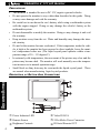
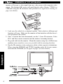
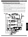
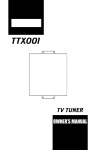
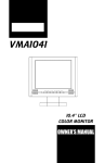
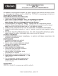
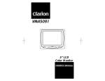
VMA6491
6.4” ACTIVE MATRIX TFT
COLOR LCD MONITOR
OWNER’S MANUAL
INSTALLATION GUIDE
OWNER’S MANUAL
WARNING!
THE CLARION VMA6491 LCD MONITOR IS DESIGNED FOR REAR SEAT PASSENGER
VIEWING ONLY.
THIS PRODUCT IS NOT INTENDED FOR VIEWING BY THE DRIVER WHILE THE
VEHICLE IS IN MOTION SINCE SUCH USE MAY DISTRACT THE DRIVER OR INTERFERE WITH THE DRIVER’S SAFE OPERATION OF THE VEHICLE AND MAY RESULT
IN SERIOUS INJURY OR DEATH. SUCH USE MAY ALSO VIOLATE STATE LAW.
CLARION DISCLAIMS ANY LIABILITY FOR ANY BODILY INJURY, INCLUDING
FATALITIES, OR PROPERTY DAMAGE THAT MAY RESULT FROM ANY IMPROPER
OR UNINTENDED USES OF THIS PRODUCT.
INTRODUCTION:
The VMA6491 is a TFT active matrix color LCD monitor which delivers a striking picture with superior image resolution. The VMA6491 integrates into a
Clarion mobile multimedia systems using a VDH9600 (mobile VCR Recorder)
even if no TTX001 (mobile TV tuner) is connected. The Clarion VMA6491 is a
full-featured 6.4" LCD Color Monitor and has the following:
•
•
•
•
6.4" wide-screen color LCD panel
A bright vibrant clear screen
RCA Video input connector
New side mount threaded holes for easy installation with all Clarion brackets
ABOUT THIS MANUAL AND WARRANTY:
To start enjoying your new Clarion VMA6491 monitor, please read the instructions listed in this manual. Keep all instructions for future reference. Please fill
out and send in the enclosed warranty card to protect your purchase and aid in
warranty service. Also, save your original sales receipt as proof of purchase.
INTRODUCTION, ABOUT THIS MANUAL & TABLE
OF
CONTENTS . . . . . . . . . . . 1
PRECAUTIONS & DESCRIPTION OF BUTTONS AND CONNECTORS . . . . . . . . . . 2
DESCRIPTION OF PICTURE ADJUSTMENT . . . . . . . . . . . . . . . . . . . . . . . . . 3
CARE
AND
MAINTENANCE . . . . . . . . . . . . . . . . . . . . . . . . . . . . . . . . . 3
WIRING PRECAUTIONS . . . . . . . . . . . . . . . . . . . . . . . . . . . . . . . . . . . 3
DESCRIPTION
OF INSTALLATION
APPLICATIONS
DESCRIPTION
...............................3
(WITH VDH9600, TTX001,
STAND ALONE SYSTEM
OF
INTRODUCTION
TABLE OF CONTENTS:
(WITH TTX001
AND
AND
FM100S)
..................5
WH100/WH200)
..............6
RC300 REMOTE BUTTONS: . . . . . . . . . . . . . . . . . . . . . . 8
TROUBLESHOOTING . . . . . . . . . . . . . . . . . . . . . . . . . . . . . . . . . . . . . 9
SPECIFICATIONS . . . . . . . . . . . . . . . . . . . . . . . . . . . . . . . . . . . . . . . . 9
1
VMA6491 6.4” TFT LCD Monitor
PRECAUTIONS:
• This monitor is intended for use in DC 12V, negative ground vehicles.
• Do not operate the monitor in ways other than described in this guide. Doing
so may cause damage and void the warranty.
• Be careful not to run down the car’s battery while using a multimedia system
with the engine stopped. Doing so may damage the vehicle’s battery or the
multimedia system.
• Do not disassemble or modify the monitor. Doing so may damage it and void
the warranty.
• Keep moisture away from the set. Water and humidity may damage the internal circuitry.
• Do not let the monitor become overheated. If the temperature inside the vehicle is high or the monitor has been exposed to direct sunlight, lower the monitor’s temperature before use. (The liquid crystal panel operates within a temperature range of 30 – 113 degrees F).
• In extremely cold temperatures, the movement of the picture may slow and the
picture may become dark. The monitor will work normally once the temperature increases to its normal operation range.
• Small black or shiny dots may be seen inside the liquid crystal panel. These
are normal when manufacturing liquid crystal products.
OF
BUTTON AND CONNECTORS:
DESCRIPTION BUTTONS
DESCRIPTION
1 Power Indicator LED
2 Remote Sensor
3 Brightness Controls
2
4 Video IN RCA
5 2-Pin Molex Power Connector
6 IR Serial Remote OUT
OWNER’S MANUAL
DESCRIPTION
OF
PICTURE ADJUSTMENT:
BRIGHTNESS:
To adjust the picture brightness, use the Brightness UP and DOWN buttons 3
located on the front panel of the VMA6491. Press and hold the UP button to
increase the picture brightness. Press and hold the DOWN button to decrease the
picture brightness (see page 2 for button locations).
VIEWING ANGLE:
To adjust the viewing angle gently tilt the cabinet to the desired position. The recommended viewing angle of the unit is – 30 to +10 degrees vertical and +45 to –45
degrees horizontal.
DESCRIPTION
OF INSTALLATION:
PICTURE ADJUSTMENT
CARE AND MAINTENANCE:
Cleaning the Cabinet:
• Use a soft, dry cloth to gently wipe off any dirt.
• Do not use benzene, thinner, car cleaner, etc., as these substances may damage
the cabinet or cause the paint to peel.
Cleaning the LCD Panel:
• Use a soft, dry cloth to gently wipe off any dust.
• The surface is easily scratched; do not rub it with hard objects.
WIRING PRECAUTIONS:
Read all wiring precautions. If you are not sure of the connections, contact your
authorized Clarion dealer.
NOTE: The VMA6491 monitor displays video images only. It does not provide audio
output. Refer to the Applications, starting on page 5, of this owner’s manual
for proper connection to Clarion’s multimedia audio output devices.
1. Disconnect the negative (-) lead from the vehicle’s battery before making any
connections.
2. When creating passage holes through metal or plastic panels, use grommets to
eliminate any sharp edges created during drilling. This will protect power or
video wires from nicks or damaged causing a possible short circuit or failure.
3. When connecting the ground lead, fasten the ground lead (black) securely to a
clean metal plate on the vehicle. Use sandpaper to remove any paint from the
surface where the ground terminal is attached.
MOUNTING HOLE LOCATIONS:
Your Clarion VMA6491 monitor, has four (4) additional side threaded mounting
holes. Now the VMA6491 is useable with all Clarion's mounting bracket methods (PQE023, ZMT009). The VMA6491 accommodates the ZMT009 gooseneck
mount when a bottom mounting screw location is necessary. The VMA6491
3
VMA6491 6.4” TFT LCD Monitor
monitor will accept a video signal from any video source with composite video
output. The Infrared (IR) sensor will work directly with a Clarion TTX001 or
VDH9600 using the IR extension cable provided (see Application starting on
page 5 for details).
INSTALLATION
1. Look over the vehicle for a monitor location. Each vehicle is different and
locations will vary. Make sure the monitor will not interfere with the driver’s
safe operation of the vehicle.
2. Once a location has been determined, run the 3.5 mm IR extension, Video
RCA and Power molex connector into the monitor’s mounting location.
3. Plug each cable into the monitor. Mount the monitor using four (4) M4x8 mm
machine screws (machine screws are provided with the mounting brackets).
4. Run the IR extension, video, and power cables to their respective destinations.
When using the VDH9600 and TTX001 together, make all of your connections near the VDH9600 (see the figure on page 5 for more details).
4
OWNER’S MANUAL
APPLICATIONS: (With the VDH9600, TTX001 and the FM100S)
1. Pick a location to mount the TTX001 TV tuner. Typically the tuner is located
close to the VCR player. Avoid areas with excessive heat or moisture.
2. Mount the TV antenna (ZCB-303 or equivalent) and plug it into the TTX001
antenna input connector.
3. Plug the 16-pin A/V Output and 2-pin Power Molex connector into the
TTX001 tuner. Using the supplied A/V cable, connect the Left (white), Right
(red), and Video (yellow) RCAs into their corresponding LINE IN locations
on the back of the VDH9600.
4. Connect the IR extension cable from the TTX001 into one of the jack inputs
on the 3.5 mm mono Y-connector (not provided). Connect the plug side of the
Y-connector to the REMOTE SENSOR INPUT on the back of the video play-
APPLICATIONS
5
VMA6491 6.4” TFT LCD Monitor
5.
6.
7.
8.
9.
er. Connect the other jack end of the Y-connector into the IR extension cable
coming from the VMA6491 monitor.
Plug the video RCA from the VMA6491 into the LINE OUT video connection on the rear of the player. Plug the provided audio RCA cable into the L/R
LINE OUT audio connections. Connect the power wires from the VMA6491,
TTX001, and the power wires of the VDH9600 together.
Remove the vehicle’s radio. Run both the audio RCAs and power wires to the
radio location and plug the audio RCAs into the FM100S audio inputs.
Mount the switch for the FM100S and run its’ power wire to the radio location. The power wires of the TTX001, video player, VMA6491 and the
FM100S can be joined and connected to the radio accessory and battery wires.
Plug the vehicle antenna into the antenna input of the FM100S. Plug the
antenna output of the FM100S into the radio.
The FM100S has a two position switch used to select the modulation frequency (88.7 or 89.1 Mhz). Pick the frequency that won’t interfere with reception
of other radio stations. Set that frequency into the radio’s preset memory.
OPERATION: (With the VDH9600, TTX001 and the FM100S)
1. Turn the vehicle ignition switch to the accessory (ACC) position.
NOTE: Since all IR signals are linked together; point any remote control at the SENSOR eye (located on the front of the VMA6491) to activate its’ component.
2. Press POWER on the player’s remote control to turn the video player ON.
3. Press POWER on the RC-300 remote control to turn the TTX001 TV tuner
ON. The TV picture is displayed on the monitor.
APPLICATIONS
NOTE: The VDH9600 automatically loops its A/V inputs through to its A/V outputs,
the video signals from the TTX001 passes through to the VMA6491.
6
4. Toggle the FM100S’s switch to the ON position and tune the radio to the
modulated frequency. Adjust the vehicle’s sound system to a comfortable
level.
5. Insert a VHS tape into the VDH9600 player and the VMA6491 monitor will
now display the player’s video and audio signals.
STAND ALONE SYSTEM: (With TTX001 and WH100/WH200)
1. Pick a location to mount the TTX001 TV tuner. Avoid areas with excessive
heat or moisture. Plug the 16-pin A/V Output connector into the TTX001
tuner.
2. Mount the TV antenna (ZCB-303 or equivalent) and plug it into the TTX001
antenna input connector.
3. Once a location has been determined for the VMA6491, run the 3.5 mm IR
extension, video RCA and 2-pin Power Molex connector into the monitor’s
OWNER’S MANUAL
mounting location. Plug each cable into the monitor. Mount the monitor
using four (4) M4x8 mm machine screws (machine screws are provided with
the mounting brackets).
4. Run the IR extension, video RCA, and power wires to the TTX001 location
and plug each into the TTX001 tuner (see the figure below for more details).
5. Pick a location to mount the WH100/200 transmitter, plug in the L/R audio
RCAs and power connector. Run the L/R RCAs and power wire to the
TTX001’s location. Mount the IR Transmitter to its mounting location. At
the TTX001, plug the L/R RCAs into the audio outputs.
6. Tie all the ground wires to a good ground point. Connect all the power wires
together and run to a fused accessory wire in the vehicle.
1. Turn the vehicle ignition switch to the accessory (ACC) position. Since the
IR signals from each of the components are linked together, point the RC-300
remote control at the SENSOR located on the front of the VMA6491.
2. Press POWER on the RC-300 remote control to turn the TTX001 TV tuner
ON. The TV picture is now displayed on the monitor.
3. Turn on the IR headphones with its power switch to listen to the audio, adjust
the volume level on the head phones to a comfortable level.
APPLICATIONS
OPERATION: (With TTX001 and WH100/WH200)
7
VMA6491 6.4” TFT LCD Monitor
DESCRIPTION
OF
RC300 REMOTE BUTTONS:
1 Number Pad
2 Skip
3 Erase/Write
4 Volume Up
5 Volume Down
6 TV/Video
7 Power
8 Channel Up
9 Mute
0 Channel Down
q Picture Select
w Auto Memory
e TV/CATV
BATTERY INSTALLATION:
• Insert 2 AAA batteries into the compartment located on the back of the unit,
observing the proper polarity.
RC300 REMOTE
NOTE: Each time the batteries are changed, the remote channels must be reprogramed. Use alkaline batteries; do not use rechargeable batteries. Always
change all the batteries at the same time.
OPERATION:
• To use the remote control, press the Power button to turn on the remote.
• Press the TV/VIDEO button to select the source to be controlled by the
remote.
• The VOL(ume) +/- buttons and the MUTE button control the TV volume.
8
OWNER’S MANUAL
TROUBLESHOOTING:
Symptom
Cause
System does not Fuse is blown.
work.
Power wires are not
connected.
The picture has The signal condishadows when con- tion is poor.
nected to the
TTX001.
Solution
Replace external fuse with the same
value.
Check the wire connections and connect it properly.
This may due to signals reflected off
buildings, mountains, etc. Check
again in a different place and direction.
The picture has
There may be interstripes or spots
ference signals.
when connected to
the TTX001.
The screen is dark. The brightness is
adjusted too low.
Usage conditions
are poor.
This may due to signal interference
from other cars, high voltage lines,
neon lights, etc. Check again in
another place.
Check that the brightness is properly
adjusted and set it properly.
This may happen if the temperature
in the vehicle is below 30°F or above
113°F. Check again when the temperature is between 30 and 113°F.
No picture on mon- The TV tuner is not Set the TV Tuner function to “TV”
itor.
mode.
set to TV mode
(using the TTX001)
The TV tuner is set In the VTR mode, no picture appears
to VTR mode.
if no video signal is being input to the
VIDEO IN terminal of the tuner.
SPECIFICATIONS:
GENERAL SPECIFICATIONS:
Supplied Accessories:
MONITOR SPECIFICATIONS:
Display Type:
Screen Size:
Pixels:
Screen Resolution:
Video Input Level:
PUT TITLE HERE
Weight:
Dimensions (w x h x d):
+12 volts dc (11-15 volts dc)
9.6 watts, Power On
0.8 amps Max (80 mA or less)
1.1 lb (0.5 kg)
7-3/8 x 5-1/8 x 1-1/4 in.
(188 x 130 x 31 mm)
3.5mm Male to Male IR extension cable (5 Meters)
Video RCA cable (5 Meters)
2-pin Molex Power connector
TROUBLESHOOTING
Power Requirement:
Power Consumption:
Color TFT Active Matrix LCD
6.4” (Actual Panel Size)
320 x 234
224,640 Dots
1.0 volts peak to peak, 75 ohms
9
PUT TITLE HERE
FCC STATEMENT
This equipment has been tested and found to comply with the limits for a Class B digital device,
pursuant to Part 16 of the FCC Rules. These limits are designed to provide reasonable protection
against harmful interference in a residential installation. This equipment generates, uses, and can
radiate radio frequency energy and, if not installed and used in accordance with the instructions,
may cause harmful interference to radio communications. However, there is no guarantee that interference will not occur in a particular installation.
If this equipment does cause harmful interference to radio or television reception, which can be verified by turning the unit off and on, the user is encouraged to consult the dealer or an experienced
radio/television technician for help.
Clarion Corporation of America
661 West Redondo Beach Blvd
Gardena, CA 90247
800-Go-Clarion
www.clarion-usa.com
©2000 Clarion Corporation, Gardena, CA
2000-VMA6491-10 Rev. 3 (6/00)