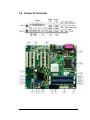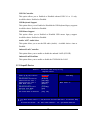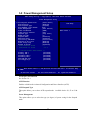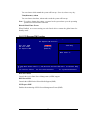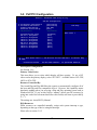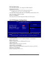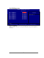
1
® Intel Core™ 2 Duo/ ® ® Pentium D/ Pentium 4/ ® Pentium Dual-Core/ Celeron™ D LGA 775 Motherboard BC945G User’s Manual v1.1 http://www.bcmcom.com USER’S NOTICE Declaration COPYRIGHT© OF THIS MANUAL BELONGS TO THE MANUFACTURER. NO PART OF THIS MANUAL, INCLUDING THE PRODUCTS AND SOFTWARE DESCRIBED IN IT MAY BE REPRODUCED, TRANSMITTED OR TRANSLATED INTO ANY LANGUAGE IN ANY FORM OR BY ANY MEANS WITHOUT WRITTEN PERMISSION OF THE MANUFACTURER. THIS MANUAL CONTAINS INFORMATION NECESSARY TO USE OF BC945G MOTHERBOARD AND WE HAVE TRY TO INCLUDE IN THIS MANUAL AS MANY INFORMATION AS POSSIBLE, BUT WE RESERVE RIGHT TO CHANGE, UPDATE ANYTIME WITHOUT PRIOR NOTICE. MANUFACTURER PROVIDES THIS MANUAL “AS IS ” WITHOUT WARRANTY OF ANY KIND, AND WILL NOT BE LIABLE FOR ANY INDIRECT, SPECIAL, INCIDENTIAL OR CONSEQUENTIAL DAMAGES (INCLUDING DAMANGES FOR LOSS OF PROFIT, LOSS OF BUSINESS, LOSS OF USE OF DATA, INTERRUPTION OF BUSINESS OF ANY KIND ALIKE). PRODUCTS AND CORPORATE NAMES APPEARING IN THIS MANUAL MAY OR MAY NOT BE REGISTERED TRADEMARKS OR COPYRIGHTS OF THEIR RESPECTIVE COMPANIES, AND THEY ARE USED ONLY FOR IDENTIFICATION OR EXPLANATION AND TO THE OWNER’S BENEFIT, WITHOUT INTENT TO INFRINGEMENT. z Intel, Core 2 Duo, Pentium® D, Pentium® 4, Pentium® Dual-Core, Celeron D are registered trademarks of Intel ® Corporation. z Microsoft ® and Windows® are registered trademarks of Microsoft ® Corporation. z AwardBIOS® are registered trademarks of Phoenix Technologies. WARNING: Replace your system’s CMOS RAM battery only with the identical CR-2032 3V Lithium-Ion coin cell (or equivalent) battery type to avoid risk of personal injury or physical damage to your equipment. Always dispose of used batteries according to the manufacturer’s instructions, or as required by the local ordinance (where applicable). This manual is created and written by BCM Technical Dept., with the information from the BC945G External Production Specifications, and Intel® 82945G Specifications. BCM provides this manual “AS IS” without warranty of any kind, and will not be liable for any indirect, special, incidental or consequential damage ( Including damages for loss or profit, loss of business, loss of use of data, interruption of business and the like). BCM reserve the right to change, correct at any time without notice. If any comments, suggestions, or errors for this manual, please write an e-mail to [email protected]. Compliance & Certificate Compliance & Certificate ISO 9001 Certificate: This device was produced in our plant with advanced quality system certified by DNV QA Ltd. in according to ISO 9001. The Certificate is valid for: DESIGN & MANUFACTURE OF MOTHERBOARD AND PERSONAL COMPUTERS. CE Declaration: CE marking is a visible declaration by the manufacturer or his authorized representatives that the electrical equipment to which it relates satisfies all the provisions of the 1994 Regulations. FCC Compliance: FCC stands for Federal Communications Commission. This product complies with FCC Rules Part 15 and has been tested, and complied with the EMI rules by a certified body. In normal operation, there shall be no harmful interference caused by this device nor shall this device accept any interference received, including interference that may cause undesired operation of this product. Easy Installation Easy Installation The following “Easy Installation” steps are for users accustomed to the assembly of a computer system. For those individuals requiring more specific information, please refer to the more detailed descriptions located within the latter chapters of this manual. Note: You must keep your power cable unplugged until the following installation steps are completed. Getting Started Touch a grounded metal surface to discharge static electricity stored in your body before unpacking your motherboard. For details please refer to Precaution. Install the CPU by correctly aligning the CPU with the socket LGA775 (refer to CPU Installation Section). Next, install the 1.8 volt unbuffered DDRII SDRAM into the 240 pin DIMM slots. Plug in any peripheral card(s) that you want to be included in the system (Warning : The PCIe-16 slot can only support Video Adaptor Card, Do not plug in any other device into the PCIe-16 slot). Plug in all cables included in the package except for the power cord. Please recheck all steps to ensure no mistakes have been made and then plug in the power cord and turn on the power to enter the BIOS setup, Chapter 3. TABLE OF CONTENT USER’S NOTICE MANUAL REVISION INFORMATION COOLING SOLUTIONS CHAPTER 1 INTRODUCTION OF BC945G MOTHERBOARD 1-1 FEATURE OF MOTHERBOARD 1-2 SPECIFICATION 1-3 LAYOUT DIAGRAM 1-4 JUMPER & CONNECTOR LOCATION CHAPTER 2 HARDWARE INSTALLATION 2-1 2-2 2-3 2-4 2-5 2-6 2-7 HARDWARE INSTALLATION STEPS CHECKING MOTHERBOARD'S JUMPER SETTING INSTALL 2-3-1 GLOSSARY 2-3-2 ABOUT INTEL LGA 775-PIN CPU INSTALL MEMORY EXPANSION CARD 2-5-1 PROCEDURE FOR EXPANSION CARD INSTALLATION 2-5-2 ASSIGNING IRQ FOR EXPANSION CARD 2-5-3 INTERRUPT REQUEST TABLE FOR THIS MOTHERBOARD CONNECTORS, HEADERS 2-6-1 CONNECTORS 2-6-2 HEADERS STARTING UP YOUR COMPUTER CHAPTER 3 INTRODUCING BIOS 3-1 ENTERING SETUP 3-2 GETTING HELP 3-3 THE MAIN MENU 3-4 STANDARD CMOS FEATURES 3-5 ADVANCED BIOS FEATURES 3-5-1 CPU FEATURE 3-6 ADVANCED CHIPSET FEATURES 3-7 INTEGRATED PERIPHERALS 3-7-1 CHIPSET IDE DEVICES 3-7-2 ONBOARD DEVICE 3-7-3 SUPER IO DEVICE 3-8 POWER MANAGEMENT SETUP 3-8-1 PCI EXPRESS PM FUNCTION 3-9 PNP/PCI CONFIGURATION 3-9-1 PCI EXPRESS CONFIGURATION 3-9-2 I RQ RESOURCES 3-10 PC HEALTH STATUS 3-10-1 SmartFAN 3-11 FREQUENCY /VOLTAGE CONTROL 3-12 LOAD MANUFACTUE SETTINGS 3-13 SET SUPERVISOR/USER PASSWORD CHAPTER 4 Configure BIOS & Set Onboard SATA RAID 4-1 BIOS SETTING 4-2 Intel RAID Utility SETTING 1 2 3 4 5 6 8 8 9 9 10 12 13 13 13 14 15 15 18 22 23 23 24 25 27 30 32 34 34 36 37 39 41 42 43 44 45 45 47 47 48 50 50 MECHANICAL DRAWING 53 i Manual Revision Information Reversion Revision History Date 1.1 Updated CPU support, H/W changes Dec. 2007 1.0 First Release May. 2006 Item Checklist 5 5 5 5 5 5 5 5 □ 1 x BC945GV Mainboard 1 x Cable for IDE/Floppy 2 x Serial ATA cable 2 x COM cable with one PCI bracket 1 x CD/ DVD for motherboard utilities 1 x BC945G Quick Reference Guide 1 x BC945G User’s Manual Digital Format on CD 1 x BC945G Standard I/O Shield Cable for USB Port 3/4 (Optional) 1 Intel Pentium 4® Processor Family Cooling Solutions As processor technology pushes to faster speeds and higher performance, thermal management becomes increasingly crucial when building computer systems. Maintaining the proper thermal environment is key to reliable, long-term system operation. The overall goal in providing the proper thermal environment is keeping the processor below its specified maximum case temperature. Heatsinks induce improved processor heat dissipation through increased surface area and concentrated airflow from attached fans. In addition, interface materials allow effective transfers of heat from the processor to the heatsink. For optimum heat transfer, Intel recommends the use of thermal grease and locking mechanism to attach the heatsink to the processor. When selecting a thermal solution for your system, please utilize an Intel recommend heatsink for use with Intel processors. Note, those heatsinks are recommended for maintaining the specified Maximum T case requirement. In addition, this collection is not intended to be a comprehensive listing of all heatsinks that support Intel processors. Please visit Intel website below for CPU installation video : http://www.intel.com/cd/channel/reseller/asmo-na/eng/100617.htm 2 Chapter 1 Introduction of BC945G Motherboard 1-1 Feature of motherboard The BC945G motherboard is design to use with Intel latest Core™ 2 Duo, Pentium® D, Pentium® 4, Pentium® Dual-Core, Celeron™ D LGA775 Processor, with HyperThreading Technology supported, the Intel 945G® Chipset delivers a high performance long life professional computing platform solution utilize the Socket LGA775 design. BC945G motherboard use the Intel 945G® Chipset Supports 533/800/1066 MHz System Bus data transfer rate. ∗ Up to 4GB Dual Channel DDR2 Memories. DDR2 is the next generation memory technology to replace the current DDR. With speeds of 400, 533 and 667 MHz, DDR2 memory provides bandwidth up to 5.3GB/s. Doubled by the dual-channel architecture, the widest memory bus bandwidth 10.7GB/s is achieved on this motherboard. The ICH7R offers 4 SATA II ports to provide speedier HDD throughout that boost overall system performance, support RAID 0 (data striping), RAID 1 (mirroring), RAID 0+1 (mirroring stripes), and RAID 5 (byte-level stripping with distributed parity), one PIDE connection support UDMA33/ATA 66/ATA 100, allows 2 IDE devices connection. With integrated Intel Graphics Media Accelerator 950 2D/3D supports 400MHz graphics core, and supports hardware motion compensation assist for software MPEG/DVD decode, by using a PCIE x16 connector, the BC945G support ADD2 DVI add on card or PCIE x16 graphics adaptor for direct digital output onboard or upgradeable high performance graphics solution . The BC945G motherboard include 2 LAN onboard, a 82573 PCI Express Gigabit Ethernet and one Intel PCI Gigabit 82541 LAN Controller. Its also has integrated onboard an AC’97 7.1 Realtek ALC883 Audio CODEC, which is fully compatible with Sound Blaster Pro® that gives you the high definition sound with back AC97 compatibility. With USB control as well as capability of expanding to 8 USB2.0 function ports to meet faster data transfer, built-in hardware monitor function. This enable system monitor and protect your computer. These motherboards provided design in hardware to protect BIOS from virus crash BIOS data. BC945G is really one of the best solution providing high performance & Longevity for Industrial, Medical Computing Applications. 3 1-2 Specification Spec Description Design ∗ Chipset ∗ ∗ CPU Socket (PLGA 775 Socket) Video Display Memory Socket Expansion Slot Integrate IDE ∗ ∗ ∗ ∗ ∗ ∗ ∗ ∗ ∗ ∗ ∗ ∗ ∗ ∗ ∗ LAN On Board Audio BIOS Multi I/O ∗ ∗ ∗ ∗ ∗ ∗ ∗ ∗ ∗ ∗ ∗ ∗ ATX form factor 4 layers PCB size: 11.6”(W) x 9.6”(D) (295 x 244 mm) Intel® 945G Graphics Memory Controller Hub (GMCH) Chipset 34mm x 34mm, 1202 balls. Intel ®82801GR I/O Controller Hub (ICH7R) Chipset 3mm x31mm, 652 balls. Support Intel Core™ 2 Duo, Pentium® D, Pentium® 4, Pentium® Dual-Core, Celeron™ D LGA775 processor Support CPU Frequency 533/800/1066 MT/s FSB Integrated Intel High Performance Graphics Media Accelerator 950 2D/3D, Graphics Core at 400MHz. Support VGA output up to 2048x1536 @ 75 Hz Support ADD2/ADD2+ card uses PCI Express graphics x16 slots 240-pin DDR2 SDRAM module socket x4 Support Memory Type 256Mbit, 512Mbit and 1Gbit Technology Support Only 8x and 16x SDRAM device with 4 banks and also supports 8 bank, 1-Gbit DDR2 Devices. Support 1.8V DDR2 400 / DDR2 533 / DDR2 667 Expandable up to 4GB 1x PCI Express x16 slot (for PCI Express Graphics Card or ADD2 ) 5x 32-bit PCI slots 1x PCI Express x4 slot One PCI IDE controllers support PCI Bus Mastering, ATA PIO/DMA and the ULTRA DMA 33/66/100 functions that deliver the data transfer rate up to 100 MB/s Four Serial ATA II host controller Data transfer up to 3.0Gb/s Raid Level 0, 1 , 5, 10 support (with ICH7R) Intel ®82541 PI 10/100/1000 PCI Gbe LAN Intel ® 82573E PCI Express Gbe LAN AC’97 Digital Audio controller integrated AC’97 7.1 Audio CODEC on board Sound Blaster Pro compliant Audio driver and utility included Award® 4MB Flash ROM PS/2 keyboard and PS/2 mouse connectors Floppy disk drive connector x1 Parallel port x1, Serial port x2 on header USB 2.0 connector x8, (4 on header) Audio connector: Line-in, Line-out, MIC, S/PDIF-IN, S/PDIF-OUT 4 1-3 System Diagram BC945G Mainboard Diagram 5 1-4 Jumper & Connector 6 Jumpers Jumper JP1 JP2 JP3 Description Clear CMOS Boot Block WP LAN EEPROM WP Note Connector Description Note J1 J2 J3 J4 J5 J6 J7 J10 J11 J12 J13 J14 J15 J16 J17 J18 J19 J20 J21 J22 J23 J24 J25 J26 J27 J28 J29 J30 J31 J32 J33 J34 J35 J36 J37 Audio Jack Audio Jack CRT VGA SPDIF-IN KB/MS Front Audio Header SPDIF-OUT CD-In LPT Port ATX 12 Connector PCI Slot 5 PCI Slot 4 PCI Slot 3 PCI Slot 2 PCI Slot 1 PCI Express x4 Slot PCI Express x16 slot (Video/ADD2) Chassis Intrusion Front USB Header 1 CPU FAN Header Front USB Header 2 System FAN Header 3 System FAN Header 4 SATA-1 SATA-3 SATA-2 SATA-4 PATA IDE COM2 Header System FAN 2 COM1 Front Panel Connector Floppy Connector ATX Power Connector System Fan Header 1 7 DB15 RCA (Yel) Mini DIN 2x5 2.54 Pitch RCA (Red) 4 Pin DB25 4 Pin Block 2 Pin Header 2x5 2.54 Pitch 4 Pin 2x5 2.54 Pitch 4 Pin 4 Pin 40 Pin 2x5 Pin Header 4 Pin 2X5 Pin 20 Pin Block 34 Pin Header 24 Pin Block 4 Pin Chapter 2 Hardware installation 2-1 Hardware installation Steps Before using your computer, you had better complete the following steps: 1. Check motherboard jumper setting 2. Install CPU and Fan 3. Install System Memory (DDR2 DIMM) 4. Install Expansion cards 5. Connect HDD and Floppy cables, Front Panel /Back Panel cable 6. Connect ATX Power cable 7. Power-On and Load Standard Default 8. Reboot 9. Install Operating System 10. Install Driver and Utility 2-2 Checking Motherboard’s Jumper Setting (1) CMOS RAM Clear (3-pin) : JP1 A battery must be used to retain the motherboard configuration in CMOS RAM short 1-2 pins of JP1 to retain the CMOS data. To clear the CMOS, follow the procedure below: 1. Turn off the system and unplug the AC power 2. Remove ATX power cable from ATX power connector 3. Remove JP1 jumper and short pins 2-3 for a few seconds 4. Return JP1 jumper to its normal setting by shorting pins 1-2 5. Connect ATX power cable back to ATX power connector Note: When should clear CMOS 1. Troubleshooting 2. Forget password 1 3 JP1 1 2-3 closed Clear CMOS 1-2 closed Normal (Default) CMOS RAM Clear Setting 8 3 JP1 2-3 Installation 2-3-1 Glossary Chipset (or core logic) – An highly integrated circuits which control the interfaces between the system processor, RAM, I/O devises, and adapter cards. Processor slot/socket - the slot or socket used to mount the system processor on the motherboard. Slot - (PCI Express, PCI, ISA, DIMM) - the slots used to mount adapter cards and system RAM. PCI Express – A latest Serial Point to Point Protocol PCI Interconnect, PCIE devices does not share bandwidth. PCI - Peripheral Component Interconnect - a high speed interface for video cards, sound cards, network interface cards, and modems; runs at 33MHz. ISA - Industry Standard Architecture - a relatively low speed interface primarily used for sound cards and modems; runs at approx. 8MHz. Serial Port - a low speed interface typically used for mouse and external modems. Parallel Port - a low speed interface typically used for printers. PS/2 - a low speed interface used for mouse and keyboards. USB - Universal Serial Bus - a medium speed interface typically used for mouse, keyboards, scanners, and some digital cameras. Sound (interface) - the interface between the sound card or integrated sound connectors and speakers, MIC, game controllers, and MIDI sound devices. LAN (interface) - Local Area Network - the interface to your local area network. BIOS (Basic Input/Output System) - the program logic used to boot up a computer and establish the relationship between the various components. Driver - software, which defines the characteristics of a device for use by another device or other software. Processor - the "Central Processing Unit" (CPU); the principal integrated circuit used for doing the "computing" in "personal computer" Front Side Bus Frequency - the working frequency of the motherboard, which is generated by the clock generator for CPU, DRAM and PCI BUS. CPU L2 Cache - the flash memory inside the CPU, normally Intel P4 CPU has 512K or above, while Celeron will have 256K. 9 2-3-2 About Intel LGA 775-pin CPU This motherboard provides a 775-pin surface mount ZIF socket (Zero Insertion Force), referred to as the LGA 775 socket supports Intel processor in the 775-land package utilizes Flip-Chip Pin Land Grid Array (FC-LGA4) package technology. The CPU should have a cooling FAN attached to prevent overheating. If this is not the case, then make sure the CPU has a sufficient cooling to dissipate heat generate from the CPU (Please check with Intel specification). WARNING! Be sure that there is sufficient air circulation across the processor’s heatsink and CPU cooling FAN is working correctly, otherwise it may cause the processor and motherboard overheat and damage, you may install an auxiliary cooling FAN, if necessary. To install a CPU, first turn off your system and remove its cover. Locate the LGA775 socket and open it by first pulling the level sideways away from the socket then upward to a 90-degree angle. Insert the CPU with the correct orientation as shown below. The notched corner should point toward the end of the level. Because the CPU has a corner pin for two of the four corners, the CPU will only fit in the orientation as shown. When you put the CPU into the ZIF socket. No force require to insert of the CPU, do not touch the socket leads, touching the socket leads may result in damage to the leads. Do not slide or twist the processor during installation. Save The Processor Socket Cover After removing the processor cover during processor installation, please save the processor socket cover. In the event that the desktop board needs to be returned for service or any time the processor is removed, the cover should be replaced on the processor socket. CPU Installation 10 This processor is intended to be professionally installed. Before installing the processor, please review the additional notes available at http://www.intel.com/go/integration. Take proper electrostatics discharge (ESD) precautions such as using appropriate ground strips, gloves, and ESD mats. 1) Open socket lever by pushing lever down 2) Open load plate (C). DO NOT TOUCH SOCKET and away from socket (A). Lift lever (B). CONTACTS (D) 3) Remove protective cover (E) from load 4) Remove processor from protective cover. (HOLD plate. Do not discard the protective cover. PROCESSOR ONLY AT EDGES, BEING CAREFUL Always replace the socket cover if the NOT TO TOUCH BOTTOM OF PROCESSOR) Do processor is removed from the socket. not discard the protective cover. Always replace the socket cover if the processor is removed from the socket. 5) Hold processor with thumb and index fingers oriented as shown. {Ensure fingers 6) Close load plate. Pressing down on load plate (I) align to socket cutouts (F)}. Align notches close and engage socket lever (J). (G) with socket (H). Lower the processor straight down without tilting or sliding the processor in the socket. 11 2-4 Install Memory The BC945G support Dual Channel Technology, operating with Dual Channel Technology, the bandwidth of Memory Bus will double up to 10.7GB/s. BC945G includes 4x DDR2 DIMM (Double Data Rate) memory socket allow up to a maximum memory size of 4.0GB. Due to chipset resource allocation, the system may detect less than 4 GB of system memory when four 1 GB DDR2 memory modules is installed. • Support 256Mb, 512Mb and 1Gb technologies implemented as x8, x16 devices. • Non-ECC un-buffered only. Use of two DDR2 memory modules in to same color DIMMs slots is strongly recommended, for optimal performance for Dual Channel Technology to work. Always install DIMMs with same CAS latency to avoid memory timing compatibility problem. It is also recommended to use memory modules from the same vendor. Valid Memory Configurations Bank DDRII 1 DDR2 DS/SS DDRII X Single Channel X DDRII 2 DS/SS DDRII DDRII 3 DS/SS DDRII DDRII 4 DS/SS DDRII Total System Memory(Max. 4.0GB) * DS Double Side, SS Single Side X Dual Channel X X X X X X X X X X X X X X X Total Memory 256MB∼1.0GB 256MB∼1.0GB 256MB∼1.0GB 256MB∼1.0GB 256MB∼4.0GB DDRII4 DDRII3 DDRII2 DDRII1 Generally, installing DDRII SDRAM modules to your motherboard is very easy, refer to figure below to see what a 240-Pin DDRII 533/DDRII 400 SDRAM module looks like. NOTE! When you install DIMM module fully into the DIMM socket the eject tab should be locked into the DIMM module very firmly and fit into its indention on both sides. 12 2-5 Expansion Cards WARNING! Turn off your power when adding or removing expansion cards or other system components. Failure to do so may cause severe damage to both your motherboard and expansion cards. 2-5-1 Procedure For Expansion Card Installation 1. Read the documentation for your expansion card and make any necessary hardware or software setting for your expansion card such as jumpers. 2. Remove your computer’s cover and the bracket plate on the slot you intend to use. 3. Align the card’s connectors and press firmly. 4. Secure the card on the slot with the screen you remove above. 5. Replace the computer system’s cover. 6. Set up the BIOS if necessary. 7. Install the necessary software driver for your expansion card. 2-5-2 Assigning IRQs For Expansion Card Some expansion cards need an IRQ to operate. Generally, an IRQ must exclusively assign to one use. In a standard design, there are 16 IRQs available but most of them are already in use. Standard Interrupt Assignments IRQ 0 1 2 3* 4* 5* 6* 7* 8 9* 10 * 11 * 12 * 13 14 * 15 * Priority N/A N/A N/A 8 9 6 11 7 N/A 10 3 2 4 N/A 5 1 Standard function System Timer Keyboard Controller Programmable Interrupt Communications Port (COM2) Communications Port (COM1) LPt2 or COM5 Floppy Disk Controller Printer Port (LPT1) System CMOS/Real Time Clock ACPI Mode when enabled IRQ Holder for PCI Steering IRQ Holder for PCI Steering PS/2 Compatible Mouse Port Numeric Data Processor Primary IDE Channel Secondary IDE Channel * These IRQs are usually available for ISA or PCI devices. 13 2-5-3 Interrupt Request Table For This Motherboard Interrupt request are shared as shown the table below: INT A INT B INT C INT D INT E PCI Slot 1 PCI Slot 2 PCI Slot 3 PCI Slot 4 PCI Slot 5 Onboard 82541PI LAN Onboard PCIE GbE LAN IMPORTANT! √ INT F INT G INT H √ √ √ √ √ If using PCI cards on shared slots, make sure that the drivers support “Shared IRQ” or that the cards don’t need IRQ assignments. Conflicts will arise between the two PCI groups that will make the system unstable or cards inoperable. 14 2-6 Connectors, Headers 2-6-1 Connectors (1) Power Connector (24-pin block) : (J36) ATX Power Supply connector. This is a newly defined 24-pin connector that usually comes with newer ATX power supplies. The ATX Power Supply allows the use a soft power on momentary switch that connect from the front panel switch to a 2-pin Power-On jumper pole on the motherboard. When the power switch on the back of the ATX power supply is turned on, the full power will not come into the system board until the front panel switch is momentarily pressed. Press this switch again will turn off the power to the system board. Pin 1 PIN ROW2 13 14 15 16 17 18 19 20 21 22 23 24 3.3V -12V GND Soft Power On GND GND GND -5V +5V +5V +5V GND ROW1 3.3V 3.3V GND 5V GND 5V GND Power OK +5V (for Soft Logic) +12V +12V +3.3V PIN 1 2 3 4 5 6 7 8 9 10 11 12 15 (2) ATX 12V Power Connector (4-pin block) : (J12) This is a newly defined 4-pin connector that usually comes with ATX Power supplies. The ATX Power supplies that fully support Pentium 4 processor must include this connector for supporting a stable 12V power consumption. Without this connector, the system may become unstable due to insufficient current to the system. Pin 1 (3) (4) (5) (6) (7) Signa l Pin Sign al 12V 2 1 GND 12V 4 3 GND PS/2 Mouse & PS/2 Keyboard Connector: (J5) The connectors for PS/2 keyboard and PS/2 Mouse. USB Port connector: USB 0/ 1(J9), USB 2/3 (J8) The connectors are 4-pin connector that connect USB devices to the system board. LAN Port connector: PCIE (J9), PCI (J8) This connector is standard RJ45 connector for Network connector. Parallel Port Connector (25-pin female): (J11) Parallel Port connector is a 25-pin D-Subminiature Receptacle connector. The On-board Parallel Port can be disabled through the BIOS SETUP. Please refer to Chapter 3’s “INTEGRATED PERIPHERALS SETUP” section for more detail information. Audio Connector : (J1, J2) This connector has 3 phone jacks for LINE-OUT, LINE-IN, MIC and the another connector with 3 phone jacks for . Audio output to speaker Line-out : Audio input to sound chip Line-in : Microphone Connector MIC : Center/ Subwoofer : Center and Subwoofer speaker out Rear speaker out Rear: Side speaker out Side: 16 (8) VGA Connector (15-pin D-Sub) Connector: VGA VGA is the 15-pin D-Subminiature female connector for display monitor. (9) Floppy drive Connector (34-pin block): FDD This connector supports the provided floppy drive ribbon cable. After connecting the single plug end to the motherboard, connect the two plugs at other end to floppy drives. FDD Pin 1 Floppy Drive Connector (10) Primary IDE Connector (40-pin block): IDE1 This connector supports the provided IDE hard disk ribbon cable. After connecting the single plug end to motherboard, connect the two plugs at other end to your hard disk(s). If you install two hard disks, you must configure the second drive to Slave mode by setting its jumpers accordingly. Please refer to the documentation of your hard disk for the jumper settings. IDE1 Pin 1 Parallel IDE Connector 17 (12) Serial ATA J26, J27, J28, J29 This connector supports Serial ATA devices. After connecting the single plug end to motherboard, connect the plug at other end to the SATA device. SATA J26, J27, J28, J29 SATA3 SATA1 SATA2 SATA0 2-6-2 Headers (1) Serial Port : COM1 (J33), COM2 (J31) COM1 & COM2 are onboard 9-pin headers. The On-board serial port can be disabled through BIOS SETUP. Please refer to Chapter 3 “INTEGRATED PERIPHERALS SETUP” section for more detail information. COM1/COM2 Signal Pin 1 Pin Signal KEY 10 5 GND RI 9 4 DTR CTS 8 3 TxD RTS 7 2 RxD DSR 6 1 DCD Serial Port COM1/ COM2 Header 18 2) Line-Out, MIC Header (9-pin): (J6) This header connect to the Front Panel Line-out, MIC connector with use of a cable. AUDIO Pin 1 2 MIC2- L MIC2- R Line2- L Front-Sense Line2- R AGND -ACZ_DET MIC-JD KEY Line2- JD 9 10 Front Audio Headers J6 VCC -DATA VCC GND +DATA -DATA Front USB 1/ 2 Headers (9-pin) : (J21, J23) These headers are used for connecting the additional USB port plugs. By attaching an option USB cable, your can be provided with two additional USB plugs affixed to the back panel. GND +DATA (3) VCC -DATA USB6/7 Pin 1 NC GND +DATA VCC -DATA NC GND +DATA Pin 1 USB4/5 USB Port Headers (4) (5) IDE Activity LED: IDE LED (J34) This connector connects to the hard disk activity indicator light on the case. Reset switch lead: RESET (J34) 19 This 2-pin connector connects to the case-mounted reset switch for rebooting your computer without having to turn off your power switch. This is a preferred method of rebooting in order to prolong the life of the system’s power supply. See the figure below. (6) (8) Power LED (J34) The Power LED is light on while the system power is on. Connect the Power LED from the system case to this pin. Power switch: PWR BTN (J34) This 2-pin connector connects to the case-mounted power switch to power ON/OFF the system. Pin 1 VCC HDDLED GND RSTSW VCC IRRX GND IRTX HDLED RESET IRDA GRN YEL PWRBTN PSW+ SMB Dat SMB Clk KEY NC PWR LED PWRBT SMBUS System Front Panel J34 (9) FAN Speed Headers (3-pin) : Chassis FAN, SYSFAN, CPUFAN These connectors support cooling fans, depending on the fan manufacturer, the wire and plug may be different. The red wire should be positive, while the black should be ground. Connect the fan’s plug to the board taking into consideration the polarity of the connector. CPU FAN HEADER CPU FAN 4 1 SYSTEM FAN2 HEADER SFAN 2 4 1 SFAN 3 1 20 4 SFAN 4 1 4 (10) CD Audio-In Headers (4-pin) : (J10) CDIN is the connector for the CD-Audio Input signal. Please connect it to CD-ROM CD-Audio output connector. CD Audio Header J10 CD-IN 1 Pin 1 2 3 4 4 J10 Signal CD-L CD-GND CD-GND CD-R (11) Chassis Intrusion (J20) Intrusion detection is triggered when these two pins are shorted. message will show during POST after the next reboot.. Signal Chassis# GND 21 Pin 1 2 A 2-7 Starting Up Your Computer 1. After all connection are made, close your computer case cover. 2. Be sure all the switches are off, and check that the power supply input voltage is set to the local voltage, usually input voltage is 220V∼240V or 110V∼120V depending on the voltage used in your country. 3. Connect the power supply cord into the power supply located on the back of your system case according to your system user’s manual. 4. Turn on your peripheral in the following order: a. Your monitor. b. Other external peripheral (Printer, Scanner, External Modem etc…) c. Your system power. For ATX power supplies, you need to turn on the power supply and then press the ATX power switch on the front side of the case. 5. The power LED on the front panel of the system case will light. The LED on the monitor may light up or switch from orange to green after the system is on, if it complies with green standards or if it is has a power standby feature. The system will then run power-on test. While the self-test is running, the BIOS will alarm beeps or additional message will appear on the screen. If you do not see any thing within 30 seconds from the time you turn on the power. The system may have failed the power-on test. Recheck your jumper settings and connections or call your retailer for assistance. Beep Meaning One short beep when displaying logo No error during POST Long beeps in an endless loop No DRAM install or detected One long beep followed by three short beeps Video card not found or video card memory bad High frequency beeps when system is working CPU overheated System running at a lower frequency 6. During power-on, press <Del> key to enter BIOS setup. instructions in BIOS SETUP. Follow the 7. Power off your computer: You must first exit or shut down your operating system before switching off the power switch. For ATX power supplies, you can press the ATX power switch to shut down your operating system. If you use Windows 2K, XP, click “Start” button, click “Shut down” and then click “Shut down the computer?” The power supply should turn off after windows shut down. 22 Chapter 3 Introducing BIOS The BIOS is a program located on a Flash Memory on the motherboard. This program is a bridge between the motherboard and the operating system. When starting the computer, the BIOS program has control of the system. The BIOS first operates an auto-diagnostic test called POST (power on self test) for all the necessary hardware, it detects the entire hardware device and configures the parameters of the hardware synchronization. After these tasks are completed, the BIOS gives up control of the computer over to the operating system (OS). Since the BIOS is the only channel for hardware and software to communicate, it is the key factor for system stability, and ensuring optimal system performance. In the BIOS Setup main menu of Figure 3-1, you can see several options. We will explain these options step by step in the following pages of this chapter, but let us first see a short description of the function keys you may use here: • Press <Esc> to quit the BIOS Setup. • Press ↑ ↓ ← → (up, down, left, right) to choose, in the main menu, the option you want to confirm or to modify. • Press <F10> when you have completed the setup of BIOS parameters to save these parameters and to exit the BIOS Setup menu. • Press Page Up/Page Down or +/– keys when you want to modify the BIOS parameters for the active option. 3-1 Entering Setup Power on the computer and keep pressing <Del> immediately until you enter Setup. If the “Enter Setup” message disappears before you had a chance to respond, restart the system to try again by turning it OFF then ON or pressing the “RESET” button on the system case. You may also restart by simultaneously pressing the <Ctrl>, <Alt> and <Delete> keys. 3-2 Getting Help Main Menu The on-line description of the highlighted setup function is displayed at the right side of the screen. 23 3-3 The Main Menu Once you enter the Award® BIOS CMOS Setup Utility, the Main Menu (Figure 3-1) will appear on the screen. The Main Menu allows you to select from fourteen setup functions and two exit choices. Use arrow keys to select among the items and press <Enter> to accept or enter the sub-menu. Phoenix – AwardBIOS CMOS Setup Utility Standard CMOS Features Frequency/ Voltage Control Advanced BIOS Features Load Fail-Safe Defaults Advanced Chipset Features Load Optimized Defaults Integrated Peripherals Set Supervisor Password Power Management Setup Set User Password PnP/PCI Configurations Save & Exit Setup PC Health Status Exit Without Saving Esc : Quit ↑↓→ ← F10 : Save & Exit Setup Time, Date, Hard Disk Type... Figure 3-1 24 : Select Item 3-4 Standard CMOS Features The items in Standard CMOS Setup Menu are divided into several categories. Use the arrow keys to highlight the item and then use the <PgUp> or <PgDn> keys to select the value you want in each item. Phoenix – AwardBIOS CMOS Setup Utility Standard CMOS Features ► ► ► ► ► ► Date (mm:dd:yy) Time (hh:mm:ss) Tue, Dec, 16 2005 11 : 26 : 48 IDE IDE IDE IDE IDE IDE None None None None None None Channel Channel Channel Channel Channel Channel 0 0 1 1 1 1 Master Slave Master Slave Master Slave Item Help Menu Level > Drive A Drive B 1.44M, 3.25 in. [None] Video Halt On [EGA/ VGA] All,But Keyboard Base Memory Extended Memory Total Memory 640K 56320K 57344K Change the day, month, year and century ↑↓→← Move Enter:Select +/-/PU/PD:Value F10:Save ESC:Exit F5:Previous Values F6: Fail-Safe Defaults F1:General Help F7: Optimized Defaults Date The date format is <day><month><date><year>. Day Month Day of the week, from Sun to Sat, determined by BIOS. Read-only. The month from Jan. through Dec. Date The date from 1 to 31 can be keyed by numeric function keys. Year The year depends on the year of the BIOS. Time The time format is <hour><minute><second>. Primary Master/Primary Slave Secondary Master/Secondary Slave Press PgUp/<+> or PgDn/<–> to select Manual, None, Auto type. Note that the specifications of your drive must match with the drive table. The hard disk will not work properly if you enter improper information for this category. If your 25 hard disk drive type is not matched or listed, you can use Manual to define your own drive type manually. If you select Manual, related information is asked to be entered to the following items. Enter the information directly from the keyboard. This information should be provided in the documentation from your hard disk vendor or the system manufacturer. Access Mode The settings are Auto, CHS, Large, and LBA. Cylinder number of cylinders Head number of heads Precomp write precomp Landing Zone landing zone Sector number of sectors Video Select the type of primary video subsystem in your computer. The BIOS usually detects the correct video type automatically. The BIOS supports a secondary video subsystem, but you do not select it in Setup. EGA/VGA Enhanced Graphics Adapter/Video Graphics Array. For EGA, VGA, SEGA, SVGA or PGA monitor adapters. CGA 40 Color Graphics Adapter, power up in 40 column mode CGA 80 Color Graphics Adapter, power up in 80 column mode MONO Monochrome adapter, includes high resolution monochrome adapters Halt On During the power-on self-test (POST), the computer stops if the BIOS detects a hardware error. You can tell the BIOS to ignore certain errors during POST and continue the boot-up process. All Errors If the BIOS detects any error, POST stops and prompts you to continue or enter BIOS setup. No Errors POST does not stop for any errors. All, But Keyboard POST stops for all errors except keyboard errors. All, But Diskette POST stops for all errors except diskette drive errors. All, But Disk/Key POST stops for all errors except keyboard or disk errors. 26 3-5 Advanced BIOS Features Phoenix – AwardBIOS CMOS Setup Utility Advanced BIOS Features ► CPU Feature ► Hard Disk Boot Priority Logo Image Virus Warning Quick Power On Self Test First Boot Device Second Boot Device Third Boot Device Boot Other Device Swap Floppy Drive Boot Up Floppy Seek Boot Up NumLock Status Gate A20 Option Typematic Rate Setting x Typematic Rate (Chars/ Sec) x Typematic Delay (Msec) Security Option APIC Mode MPS Version Control For OS OS Select For DRAM > 64 MB Console Redirection X Baud Rate Agent after boot Report No FDD For WIN 95 ASF support DMI Event Log Clear All DMI Event Log View DMI Event Log Mark DMI Events as Read Event Log Capacity Event Log Validity [Press Enter] [Press Enter] [Disabled] [Disabled] [Enabled] [Floppy] [CDROM] [Hard Disk] [Enabled] [Disabled] [Enabled] [On] [Fast] [Disabled] 6 250 [Setup] [Enabled] [1.4] [Non-OS2] [Disabled] 19200 [Enabled] [No] [Enabled] [Enabled] [No] [Enter] [Enter] Space Available Valid Item Help Menu Level > ↑↓→← Move Enter:Select +/-/PU/PD:Value F10:Save ESC:Exit F5:Previous Values F6: Fail-Safe Defaults CPU Feature See 3-5-1. Hard Disk Boot Priority See 3-5-2. Logo Image Select a logo to be shown during bootup. Virus Warning 27 F1:General Help F7: Optimized Defaults Allow you to enabled or disabled boot sector overwrite protection Quick Power On Self Test Select Enabled to reduce the amount of test ran during power-on self-test (POST). First/Second/Third Boot Device Selects order for boot devices Boot Other Device If enabled, the BIOS will check for unlisted boot devices after it has failed to boot from the three listed boot devices. Swap Floppy Drive This field is effective only in systems with two floppy drives. Selecting Enabled assigns physical drive B to logical drive A, and physical drive A to logical drive B. Boot Up Floppy Seek When Enabled, the BIOS tests (seeks) floppy drives to determine whether they have 40 or 80 tracks. Boot Up NumLock Status Controls the state of the NumLock key when the system boots. Gate A20 Option Refers to the way the system addresses memory above 1 MB (extended memory). When set to Fast, the system chipset controls Gate A20. When set to Normal, a pin in the keyboard controller controls Gate A20. Setting Gate A20 to Fast improves system speed, particularly with OS/2 and Windows. Typematic Rate Setting When Enabled, you can select a typematic rate and typematic delay. Security Option If you have set a password, select whether the password is required every time the System boots, or only when you enter Setup. APIC Mode The Advanced Programmable Interrupt Controller (APIC) prioritizes interrupts. MPS Version Control For OS Allows the operating system to work with multiple CPUs. compatibility with older OS. OS Select For DRAM > 64MB 28 Select “1.1” for Enable only if you are running OS/2 operating system with greater than 64 MB of RAM on your system. Console Redirection “Enabled” redirects console to COM port; “Disabled” redirects when keyboard is absent. Agent after boot If enabled, this keeps agent running after OS boots. Report No FDD For WIN 95 If no floppy drive is used for Win95, select “Yes” for compatibility reasons. ASF support Enable Alert Standard Format (ASF) provides advance warning and system failure, and should be enabled for remote system management. DMI Event Log Enables logging of Desktop Management Interface (DMI) events. 29 3-5-1 CPU Feature Phoenix – AwardBIOS CMOS Setup Utility CPU Feature Delay Prior to Thermal [16 Min] Item Help 1800 Penn St Thermal Monitor 1 Limit CPUID MaxVal [Disabled] Execute Disable Bit [Enabled] Menu Level > ↑↓→← Move Enter:Select +/-/PU/PD:Value F10:Save ESC:Exit F5:Previous Values F6: Fail-Safe Defaults F1:General Help F7: Optimized Defaults Delay Prior to Thermal Some Intel processors have a function called Thermal Control Circuit (TCC) to prevent overheating of the CPU. When TCC is activated, the CPU idles about 5070% of the time to cool down the processor. During bootup, the CPU will typically heat up during heavy load, and it is not desired to trigger the TCC too early because it will reduce performance. Settings are 4, 8, 16, and 32 minutes. Limit CPUID MaxVal Intel Penitum 4 with Hyper-Threading Technology processors report a higher CPUID than “3”. Older operating systems are not able to recognize this, so this setting should be enabled if using such OS. Execute Disable Bit When enabled, this feature protects areas of memory from malicious code. 30 3-5-2 Hard Disk Boot Priority Phoenix – AwardBIOS CMOS Setup Utility Hard Disk Boot Priority 1. Bootable Add-In Cards Item Help Menu Level > ↑↓→← Move Enter:Select +/-/PU/PD:Value F10:Save ESC:Exit F5:Previous Values F6: Fail-Safe Defaults F1:General Help F7: Optimized Defaults Hard Disk Boot Priority Use arrow key to select a device, and <Pg Up>/<Pg Down> to change . 31 3-6 Advanced Chipset Features Phoenix – AwardBIOS CMOS Setup Utility Advanced Chipset Features x x x x DRAM Timing Selectable DRAM RAS# to CAS# Delay DRAM RAS# Precharge Precharge delay (tRAS) System Memory Frequency System BIOS Cacheable Video BIOS Cacheable AMT BIOS Support [By SPD] Auto Auto Auto Auto [Enabled] [Disabled] [Disabled] ** VGA Setting ** PEG/Onchip VGA Control On-Chip Frame Buffer Size DVMT Mode DVMT/FIXED Memory Size [Auto] [ 8MB] [DVMT] [ 128MB] Item Help Menu Level > ↑↓→← Move Enter:Select +/-/PU/PD:Value F10:Save ESC:Exit F5:Previous Values F6: Fail-Safe Defaults F1:General Help F7: Optimized Defaults DRAM Timing Selectable Control the module). DRAM timing manually by the SPD (EEPROM on the RAM DRAM RAS# To CAS# Delay This field allow you to insert a timing delay between the CAS and RAS strobe. Avalable choices: 2 or 3. DRAM RAS# Precharge Select the number of CPU clocks allocated for the RAS# signal to accumulate its charge before the DRAM is refreshed. Available choice : 2 or 3. Precharge delay (tRAS) Select the delay between active and precharge command. System Memory Frequency Sets the frequency of the RAM module. 32 System BIOS Cacheable This option allow you to Enable or Disable the system BIOS to be cache to DRAM. Available choice: Enabled or Disabled. Video BIOS Cacheable: This Option Allow you to Enable or Disable the video BIOS to be cache to DRAM. Available choice: Enabled or Disabled. AMT BIOS Support Enables AMT; After reboot, hit Ctrl+P to enter AMT setup. PEG/Onchip VGA Control Select between Onchip VGA or PCIe graphics card. On-Chip Frame Buffer Size This item allows you to set the on-chip frame buffer size. Available choice: 1M, 8M. DVMT Mode This item allows you to select the Dynamic Video Memory Technology (DVMT) to a Fixed (constant), DVMT (dynamic) or Both (minimum is constant, but allows it to dynamically increase). DVMT/FIXED Memory Size This item allows you to select the DVMT/ Fixed Memory Size. Available choice: 64MB or 128MB. 33 3-7 Integrated Peripherals Phoenix – AwardBIOS CMOS Setup Utility Integrated Peripherals ► OnChip IDE Device ► Onboard Device ► SuperIO Device [Press Enter] [Press Enter] [Press Enter] Item Help Menu Level > ↑↓→← Move Enter:Select +/-/PU/PD:Value F10:Save ESC:Exit F5:Previous Values F6: Fail-Safe Defaults F1:General Help F7: Optimized Defaults 3-7-1 Chipset IDE Devices Phoenix – AwardBIOS CMOS Setup Utility On Chip IDE Device IDE HDD Block Mode IDE DMA transfer access On-Chip Primary PCI IDE IDE Primary Master PIO IDE Primary Slave PIO IDE Primary Master UDMA IDE Primary Slave UDMA [Enabled] [Enabled] [Enabled] [Auto] [Auto] [Auto] [Auto] Item Help Menu Level >> *** On-Chip Serial ATA Setting *** SATA Mode [IDE] Chipset Serial SATA [Auto] x SATA Port Speed Settings [Disabled] x PATA IDE Mode [Primary] SATA Port P1, P3 is Secondary ↑↓→← Move Enter:Select +/-/PU/PD:Value F10:Save ESC:Exit F5:Previous Values F6: Fail-Safe Defaults 34 F1:General Help F7: Optimized Defaults IDE HDD Block Mode Block mode is also called block transfer, multiple commands, or multiple sector read/write. If your IDE hard drive supports block mode (most new drives do), select Enabled for automatic detection of the optimal number of block read/writes per sector the drive can support. IDE DMA transfer access On-Chip Primary PCI IDE Enables the Primary IDE channel. IDE Primary Master PIO Selects the PIO mode for Primary IDE Master. Avalable options are: Auto, Mode 0, Mode 1, Mode 2, Mode 3 or Mode 4. IDE Primary Slave PIO Selects the PIO mode for Primary IDE Slave. Avalable options are: Auto, Mode 0, Mode 1, Mode 2, Mode 3 or Mode 4. IDE Primary Master UDMA Enables UDMA detection for Primary IDE Master. Available options are: Auto or Disabled. IDE Primary Slave UDMA Enables UDMA detection for Primary IDE Slave. Available options are: Auto or Disabled. SATA Mode Selects mode of operation for SATA function. IDE - no AHCI, no RAID; SATA drives operate as standard IDE drives. RAID - AHCI enabled, RAID enabled; Redundant Array of Independent Disks (RAID) provides features for fault tolerance and/or performance. AHCI - AHCI enabled, no RAID; Advanced Host Controller Interface (AHCI) enables advanced Serial ATA features such as Native Command Queuing and hot plug. On-Chip Serial ATA Selects the different modes for the SATA controller. Disabled: Disables SATA controller Auto: Auto arrange by BIOS 35 Combined Mode: PATA and SATA are combined. Max of 2 IDE drives in each channel. Enhanced Mode: Enable both SATA and PATA. Max of 6 IDE drives are supported. SATA Only: SATA is operating in legacy mode. SATA PORT Speed Settings This item allows you to select the speed of SATA ports. [Disabled] Disable this function. [Force GEN I] Force the data transfer rates to 1.5Gb/s(150 MB/s) [Force GEN II] Force the data transfer rates to 3.0Gb/s(300 MB/s) PATA IDE Mode Changes mode for SATA Port. Primary: P1, P3 is Secondary Secondary: P0, P2 is Primary 3-7-2 Onboard Device Phoenix – AwardBIOS CMOS Setup Utility Onboard Device USB Controller USB 2.0 Controller USB Keyboard Support USB Mouse Support Azalia/AC97 Audio Select Onboard Lan2 Controller Onboard Lan2 BootRom [Enable] [Enable] [Disabled] [Disabled] [Auto] [Enabled] [Disabled] Item Help Menu Level >> ↑↓→← Move Enter:Select +/-/PU/PD:Value F10:Save ESC:Exit F5:Previous Values F6: Fail-Safe Defaults F1:General Help F7: Optimized Defaults USB Controller This option allows you to Enabled or Disabled the onboard USB controller. Available choices: Enabled or Disabled. 36 USB 2.0 Controller This option allows you to Enabled or Disabled onboard USB 2.0 or 1.1 only. Available choice: Enabled or Disabled. USB Keyboard Support This option allows you to Enabled or Disabled the USB keyboard legacy supports. Available choice: Enabled or Disabled. USB Mouse Support This option allows you to Enabled or Disabled USB mouse legacy support. Available choice: Enabled or Disabled. Azalia/ AC97 Audio Select This option allows you to use the HD audio (Azalia). Available choice: Auto or Disabled. Onboard Lan2 Controller This option allows you to enable or disable the onboard LAN2 (82541PI). Onboard Lan2 BootRom This option allows you to enable or disable the PXE ROM for LAN2. 3-7-3 SuperIO Device Phoenix – AwardBIOS CMOS Setup Utility SuperIO Device Power Up By PS/2 Device x Hot Key Select Onboard FDC Controller Onboard Serial Port 1 Onboard Serial Prot 2 UART Mode Select x UR2 Duplex Mode Onboard Parallel Port Parallel Port Mode x ECP Mode Use DMA PSU State When AC Returns [Disabled] Ctrl-F1 [Enabled] [3F8/IRQ4] [2F8/IRQ3] [Normal] Half [378/IRQ7] [SPP] 3 [Stay Off] Item Help Menu Level >> ↑↓→← Move Enter:Select +/-/PU/PD:Value F10:Save ESC:Exit F5:Previous Values F6: Fail-Safe Defaults 37 F1:General Help F7: Optimized Defaults Power Up By PS/2 Device Enables the system to be turned on through PS/2 keyboard or mouse. Hot Key Select Sets the Hot Key to turn on the system. Onboard FDC Controller Select Enabled if your system has a floppy disk controller (FDC) installed on the system board and you wish to use it. If you install add-on FDC or the system has no floppy drive, select Disabled in this field. The settings are: Enabled and Disabled. Onboard Serial Port 1/2 Select an address and corresponding interrupt for the first and the second serial ports. Available settings are: 3F8/IRQ4, 2E8/IRQ3, 3E8/IRQ4, 2F8/IRQ3, Disabled, Auto. UART Mode Select Selects the mode the UART operates under. Aavailble settings are: Normal, IrDA, ASKIR, or SCR. Onboard Parallel Port: There is a built-in parallel port on the on-board Super I/O chipset that provides Standard, ECP, and EPP features. It has the following option: Disabled (3BCH/IRQ7)/ Line Printer port 0 (278H/IRQ5)/ Line Printer port 2 (378H/IRQ7) Parallel Port Mode Line Printer port 1 SPP : Standard Parallel Port EPP : Enhanced Parallel Port ECP : Extended Capability Port SPP/EPP/ECP/ECP+EPP To operate the onboard parallel port as Standard Parallel Port only, choose “SPP.” To operate the onboard parallel port in the EPP modes simultaneously, choose “EPP.” By choosing “ECP”, the onboard parallel port will operate in ECP mode only. Choosing “ECP+EPP” will allow the onboard parallel port to support both the ECP and EPP modes simultaneously. ECP Mode Use DMA If ECP is selected, DMA channel 1 or 3 must be chosen. PWRON After PWR-Fail This item allows you to select system power status after power is lost. Available choice: Off, On, Former-Sts. 38 3-8 Power Management Setup CMOS Setup Utility – Copyright(C) 1984-2002 Award Software Power Management Setup ► PCI Express PM Function ACPI Function ACPI Suspend Type Run VGABIOS if S3 Resume Power Management Video Off Method Video Off In Suspend Suspend Type Modem Use IRQ Suspend Mode HDD Power Down Soft-Off by PWR-BTTN Wake-Up by PCI card Power On by Ring Resume by Alarm x Date(of Month) Alarm x Time(hh:mm:ss) Alarm [Press Enter] [Enabled] [S2(STR)] Auto [User Define] [DPMS] [Yes] [Stop Grant] [3] [Disabled] [Disabled] [Instant-Off] [Enabled] [Enabled] [Disabled] 0 0:0:0 Item Help Menu Level > ** Reload Global Timer Events ** Primary IDE 0 [Disabled] Primary IDE 1 [Disabled] Secondary IDE 0 [Disabled] Secondary IDE 1 [Disabled] FDD,COM,LPT Port [Disabled] PCI PIRQ[A-D]# [Disabled] ↑↓→← Move Enter:Select +/-/PU/PD:Value F10:Save ESC:Exit F5:Previous Values F6: Fail-Safe Defaults F1:General Help F7: Optimized Defaults PCI Express PM Function See Section 3-8-1 ACPI Function Enables or disables the Advanced Configuration and Power Interface (ACPI). ACPI Suspend Type This option allows you to select ACPI suspend mode. Available choice: S1, S3 or S1 & S3. Power Management This option allows you to select the type (or degree) of power saving for the Suspend mode. 39 Video Off Method Determines the manner in which the monitor is blanked. Blank Screen System: only writes blanks to the video buffer. V/H SYNC+Blank: System turns off vertical and horizontal synchronization ports and writes blanks to the video buffer. DPMS: Display Power Management Signaling (DPMS) mode uses the software supplied for your video subsystem to select video power management values. Video Off In Suspend Determines whether the video is turned off under Suspend Mode. Suspend Type Selects the behavior of the CPU after it enters Suspend Mode. Stop Grant: CPU goes into idle mode during power saving mode PwrOn Suspend: CPU and system remain powered on in suspend mode MODEM Use IRQ Name the interrupt request (IRQ) line assigned to the modem (if any) on your system. Activity of the selected IRQ always awakens the system. Suspend Mode After the selected period of system inactivity, all devices except the CPU shut off. HDD Power Down After the selected period of drive inactivity, the hard disk drive powers down while all other devices remain active. Soft-Off by PWR-BTTN When Enabled, turning the system off with the on/off button places the system in a very low-power-usage state, with only enough circuitry receiving power to detect power button activity or Resume by Ring activity. Wake-Up by PCI card When Disabled is selected, the system will ignore any incoming call from the PCI card/modem. When Enabled is selected, the system will boot up if there’s an incoming call from the PCI card /modem. Power On by Ring An input signal on the Ring Indicator (RI) line (such as a modem) that awakens the system from the off state. Resume by Alarm This function is for setting date and time for your computer to boot up. During Disabled, you cannot use this function. During Enabled, choose the Date and Time Alarm: Date(of month) Alarm 40 You can choose which month the system will boot up. Set to 0, to boot every day. Time(hh:mm:ss) Alarm You can choose what hour, minute and second the system will boot up. Note: If you have change the setting, you must let the system boot up to the operating system before this function will work Reload Global Timer Events When Enabled, an event occurring on each listed device restarts the global timer for Standby mode 3-8-1 PCI Express PM Function Phoenix – AwardBIOS CMOS Setup Utility PCI Express PM Function Root Port ASPM DMI Port ASPM PCI Express PME [Disabled] [Disabled] [Enabled] Item Help Menu Level >> ↑↓→← Move Enter:Select +/-/PU/PD:Value F10:Save ESC:Exit F5:Previous Values F6: Fail-Safe Defaults F7: Optimized Defaults Root Port ASPM Controls the Active State Power Management (ASPM) support. DMI Port ASPM Controls the ASPM for the Direct Media Support (DMI). PCI Express PME Enables the monitoring of PCIe Power Management Events (PME). 41 F1:General Help 3-9 PnP/PCI Configuration Phoenix – AwardBIOS CMOS Setup Utility PnP/PCI Configuration ► PCI Express Configuration ► PCI Add-on ROM Control Primary Video Device Resources Controlled By x IRQ Resources PCI/VGA INT Pin INT Pin INT Pin INT Pin INT Pin INT Pin INT Pin INT Pin [Press Enter] [Press Enter] [PCI GFX] [Auto] Press Enter Palette Snoop 1 Assignment 2 Assignment 3 Assignment 4 Assignment 5 Assignment 6 Assignment 7 Assignment 8 Assignment [Disabled] [Auto] [Auto] [Auto] [Auto] [Auto] [Auto] [Auto] [Auto] Item Help Menu Level > ↑↓→← Move Enter:Select +/-/PU/PD:Value F10:Save ESC:Exit F5:Previous Values F6:Fai-Safe Defaults F1:General Help F7:Optimized Defaults PCI Express Configuration See Section 3-9-1. Primary Video Device This item allows you to select which display will have priority. To use a PCI video card as the primary display, select “PCI GFX”. Available choice: PCI GFX, i945G or PCIe GFX. Resource Controlled By: The Award Plug and Play BIOS has the capacity to automatically configure all of the boot and Plug and Play compatible devices. However, this capability means absolutely nothing unless you are using a Plug and Play operating system such as Windows®95/98. If you set this field to “manual” choose specific resources by going into each of the sub menu that follows this field (a sub menu is preceded by a “>”). The settings are: Auto(ESCD), Manual. IRQ Resources: When resources are controlled manually, assign each system interrupt a type, depending on the type of device using the interrupt. Please refer to section 3-9-2 42 PCI/VGA Palette Snoop: Leave this field at Disabled. The settings are Enabled, Disabled. Maximum Payload Size: This item allows you to select the PCIE data packet payload size. Available choice: 128, 256, 512, 1024, 2048 or 4096. Leave this field at Disabled unless there is a compatibility problem with the video card. The settings are Enabled, Disabled. INT Pin 1-8 Assignment This setting allows the manual assignment of IRQs to the Interrupt pins. 3-9-1 PCI Express Configurations Phoenix – AwardBIOS CMOS Setup Utility PCI Express Configuration PCI Express x4 Slot ROM on PCIe x4 Slot Onboard PCIe LAN1 Onboard PCIe LAN1 BootROM PCI Express V1.0a Support [Auto] [Auto] [Auto] [Disabled] [Enabled] Item Help Menu Level > ↑↓→← Move Enter:Select +/-/PU/PD:Value F10:Save ESC:Exit F5:Previous Values F6:Fai-Safe Defaults F1:General Help F7:Optimized Defaults PCI Express x4 Slot Controls whether the PCIe x4 slot is Enabled, Disabled, or Auto-detected. ROM on PCIe x4 Slot Enables or disables the device’s ROM on the PCIe x4 slot. Onboard PCIe Lan1 Enables or disables PCIe LAN device (82573E). Onboard PCIe Lan1 BootROM Enables or disables the BootROM (PXE) from the PCIe LAN device (82573E). PCI Express V1.0a Support Enables compatibility for PCIe v1.0a. 43 3-9-2 IRQ Resources Phoenix- AwardBIOS CMOS Utility IRQ Resources IRQ-3 IRQ-4 IRQ-5 IRQ-7 IRQ-9 IRQ-10 IRQ-11 IRQ-12 IRQ-14 IRQ-15 assigned assigned assigned assigned assigned assigned assigned assigned assigned assigned to to to to to to to to to to [PCI [PCI [PCI [PCI [PCI [PCI [PCI [PCI [PCI [PCI Device] Device] Device] Device] Device] Device] Device] Device] Device] Device] Item Help Menu Level >> ↑↓→← Move Enter:Select +/-/PU/PD:Value F10:Save ESC:Exit F1:General Help F5:Previous Values F6:Optimized Defaults F7:Standard Defaults IRQ 3-15 assigned to Change setting to “Reserved” so the specific IRQ does not get auto-assigned to a PCI device. 44 3-10 PC Health Status This section shows the status of your CPU, Fan, Warning for overall system status. This is only available if there is Hardware Monitor onboard. Phoenix – AwardBIOS CMOS Setup Utility PC Health Status Vcore +1.8V +3.3V + 5V + 12V - 12V -5VSB Battery Voltage CPU Temperature System Temperature PWM Temperature CPUFAN Rotation Speed SYSFAN Rotation Speed SYSFAN1 Rotation Speed SYSFAN2 Rotation Speed SYSFAN3 Rotation Speed SYSFAN4 Rotation Speed CPU Shutdown Temperature Chassis Intruder Detect 1.34V 1.74V 3.28V 6.85V 11.20V (-)11.29V 5.10V 3.16V 42ºC 33ºC 38ºC 3515 RMP 0 RMP 0 RMP 0 RMP 0 RMP 0 RMP [Disabled] [Enabled] Item Help Menu Level > ↑↓→← Move Enter:Select +/-/PU/PD:Value F10:Save ESC:Exit F5:Previous Values F6: Fail-Safe Defaults F1:General Help F7: Optimized Defaults 3-10-1 SmartFan CPU Fan PWM Control Mode Select a fixed duty cycle for the fan speed, or "SmartFan" for customized control SmartFan PWM Start Select fixed duty cycle for temperatures less "Lo-Limit" SmartFan PWM Gradient Select the increment for each degree between "Lo-Limit" and "Hi-Limit" Tcpu (SmartFan Lo-Limit) Select the low boundary for SmartFan to override fixed duty cycle 45 Tcpu (SmartFan Hi-Limit) Select the minimum temperature before fan operates at 100% speed The SmartFan function allows the user to increase or decrease the speed of the fan. This, in turn, provides control over the cooling and noise that is generated. To enable this function, CPU Fan PWM Control Mode should be selected as SmartFan. The Tcpu (SmartFan Lo-Limit) setting sets when the SmartFan function will be triggered, and SmartFan PWM Start would indicate the starting speed of the fan. Next choose a SmartFan PWM Gradient that will describe the incrementing step for each increase of temperature. (See image below.) Lastly, the Tcpu (SmartFan Hi-Limit) will determine when the fan should be adjusted to max speed when the CPU gets too hot. For example, if the “lo-limit” was set at 35ºC, “PWM start” at 30%, “PWM gradient” at 1.56%, and “hi-limit” at 65ºC, then the fan will initially be at 30% duty cycle. At each degree of temperature increase, the fan will increase 1.56% duty cycle. Therefore at 36ºC, the fan will operate at 31.56%, at 37%, it will be at 33.12%, and so on. At 65ºC, the fan will jump to 100%, and decrease when the temperature lowers. 46 3-11 Frequency/ Voltage Control This section is for setting CPU Frequency/Voltage Control. Phoenix – AwardBIOS CMOS Setup Uitility Frequency/Voltage Control Auto Detect PCI Clk [Enabled] Spread Spectrum [Disabled] Item Help Menu Level > ↑↓→← Move Enter:Select +/-/PU/PD:Value F10:Save ESC:Exit F5:Previous Values F6: Fail-Safe Defaults F1:General Help F7: Optimized Defaults Auto Detect PCI Clk When Enabled, this feature turns off the PCI clock when there is no activity on the PCI device. This is commonly used to reduce EMI. Spread Spectrum Spreads the energy of a single frequency over a wide band of frequencies to remove spikes. This is commonly used to reduce EMI. 3-12 Load Manufacture Settings Load Fail-Safe Defaults: When you press <Enter> on this item, you get a confirmation dialog box with a message similar to: Restore Fail-Safe Settings (Y/N)? N Pressing <Y> loads the default values that are factory settings for optimal performance system operations. Load Optimized Defaults: When you press <Enter> on this item, you get confirmation dialog box with a message similar to: Load Optimized Defaults (Y/N)? N 47 Pressing <Y> loads the BIOS default values for the most stable, minimalperformance system operations. 3-13 Set Supervisor/ User Password You can set either supervisor or user password, or both of them. The differences are: User password: Can only enter but do not have the right to change the options of the setup menus. When you select this function, the following message will appear at the center of the screen to assist you in creating a password. ENTER PASSWORD: Type the password, up to eight characters in length, and press <Enter>. The password typed now will clear any previously entered password from CMOS memory. You will be asked to confirm the password. Type the password again and press <Enter>. You may also press <Esc> to abort the selection and not enter a password. To disable a password, just press <Enter> when you are prompted to enter the password. A message will confirm that the password will be disabled. Once the password is disabled, the system will boot and you can enter Setup freely. PASSWORD DISABLED. When a password has been enabled, you will be prompted to enter it every time you try to enter Setup. This prevents an unauthorized person from changing any part of your system configuration. Additionally, when a password is enabled, you can also require the BIOS to request a password every time your system is rebooted. This would prevent unauthorized use of your computer. You determine when the password is required within the BIOS Features Setup Menu and its Security option. If the Security option is set to “System”, the password will be required both at boot and at entry to Setup. If set to “Setup”, prompting only occurs when trying to enter Setup. 48 3-14 Exit Leave Setup program, System will restart after saving setting to CMOS when “Save Change and Exit” is selected. If “Discard change and Exit” is selected, system will restart without saving any changes. 49 Chapter 4 Configuring BIOS and setting the Onboard SATA RAID BIOS 1. BIOS Setting: Step1. Enter BIOS, and set “RAID/SCSI/Add-on” as one of the boot sequence. Step2. Under the option of “Peripherals”, make sure the option “Onboard Intel SATA RAID” is set as “Enabled”. Step3. Save settings and exit the BIOS. 2. Intel RAID Utility setting: • RAID 0 Step1. During post, after the system has displayed the IDE information, the Intel RAID utility shall appear. Press “CRTL + I” to enter the Intel RAID BIOS setup utility. Step2. If you want to create RAID array, select Create RAID Volume in main menu and press ENTER. 50 Step3. “Create Volume Menu” will be prompted. Step4. Setup the name for RAID. Step5. Set RAID Level to “RAID 0 (Stripe). Step6. Set Strip size as 128KB (Default). Step7. The Capacity option will identify the built RAID-0 drive size. Step8. Pick the option of “Create Volume”. Step9. The system will prompt with the message “Are you sure you want to create this volume (Y/N):” Step10. Press “Y” to confirm the volume creation process. Step11. Back to main menu, pick the last option to exit the utility. RAID 1, 1+0, and 5 can be installed in the same way by selecting a different option for Step5. 51 2. WinXP/2k installation: Step1. At the beginning of Windows installation, when the blue background installation prompt appeared, press F6 several times. This will prompt WinXP/2k to add the specific mass storage driver. Step2. When asked for the specific mass storage driver, press “S”. Step3. drive. Insert the prepared “Intel ICH7R RAID driver disk” into the floppy Step4. The screen will display a series of drivers available to install, pick the option “Intel 82801GR/GH SATA RAID Controller (Desktop ICH7R)”. Step5. The Windows will prompted with the following message: “Setup will load support for the following mass storage device(s): Intel® 82801GR/GH SATA RAID controller (Desktop ICH7R)”. Press “ENT” to continue Windows installation process. 52 Mechanical Draw BC945G Mechanical Drawing 53