1
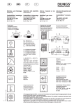
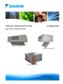
ThinLine® Horizontal Fan Coils
Catalog 724-2
Type FCHC, FCHH and FCHR
Exposed Horizontal Cabinet
Recessed Horizontal Cabinet
Concealed Horizontal Model
Table of Contents
Nomenclature and Certification . . . . . . . . . . . . . . . . . 3
Unit Selection . . . . . . . . . . . . . . . . . . . . . . . . . . . . . . . 16
Features and Benefits . . . . . . . . . . . . . . . . . . . . . . . . . 4
Basic design data . . . . . . . . . . . . . . . . . . . . . . . . . 16
The ThinLine Advantage . . . . . . . . . . . . . . . . . . . . . . 5
Unit Size . . . . . . . . . . . . . . . . . . . . . . . . . . . . . . . . 16
Options and Accessories . . . . . . . . . . . . . . . . . . . . . . 6
Coil Types . . . . . . . . . . . . . . . . . . . . . . . . . . . . . . . 16
Model Configurations . . . . . . . . . . . . . . . . . . . . . . . . . 6
Performance Data . . . . . . . . . . . . . . . . . . . . . . . . . . . 17
Hideaway units model FCHH
Cabinet units model FCHC
. . . . . . . . . . . . . . . 6
Two-Pipe Systems - Hot Water Heat . . . . . . . . . . . . 17
. . . . . . . . . . . . . . . . . 6
Four-Pipe Systems - Hot Water Preheat or Reheat
(Standard or High Capacity) . . . . . . . . . . . . . . . . . . . 18
Recessed units model FCHR
. . . . . . . . . . . . . . . 6
Options . . . . . . . . . . . . . . . . . . . . . . . . . . . . . . . . . . . . 7
Control Options . . . . . . . . . . . . . . . . . . . . . . . . . . . . . 8
Manual 4-Position Fan Switch
. . . . . . . . . . . . . . 8
Remote-Mounted Thermostats . . . . . . . . . . . . . . . . 8
Analog Thermostats . . . . . . . . . . . . . . . . . . . . . . . . 8
Digital Thermostats
. . . . . . . . . . . . . . . . . . . . . . . 8
Low Voltage Interface Board
. . . . . . . . . . . . . . . . 9
MicroTech Controllers . . . . . . . . . . . . . . . . . . . . . . . 10
Four-Pipe Systems - Steam Preheat or Reheat . . . . 19
Air Volume Capacity Data . . . . . . . . . . . . . . . . . . . . 20
Electrical Data . . . . . . . . . . . . . . . . . . . . . . . . . . . . . . 22
Electric Heaters . . . . . . . . . . . . . . . . . . . . . . . . . . . . 22
Motor Electrical Data . . . . . . . . . . . . . . . . . . . . . . . . 22
Physical Data . . . . . . . . . . . . . . . . . . . . . . . . . . . . . . . 23
Unit Data . . . . . . . . . . . . . . . . . . . . . . . . . . . . . . . . . 23
Unit Dimensions . . . . . . . . . . . . . . . . . . . . . . . . . . . . 24
Sensors . . . . . . . . . . . . . . . . . . . . . . . . . . . . . . . . . . 10
Engineering Guide Specification . . . . . . . . . . . . . . . 32
Remote-mounted Room Temperature Sensor
with Timed Override . . . . . . . . . . . . . . . . . . . . . 10
Part 1: General . . . . . . . . . . . . . . . . . . . . . . . . . . . 32
Part 2: Products . . . . . . . . . . . . . . . . . . . . . . . . . . 32
Room Temperature Sensor with Setpoint
Adjustable Module and Fan Speed Control . . . . . 10
Part 3: Execution . . . . . . . . . . . . . . . . . . . . . . . . . . 36
Customer-Supplied Controls . . . . . . . . . . . . . . . . . . 10
Factory Valve & Piping Packages . . . . . . . . . . . . . . . 11
Control Valve Options . . . . . . . . . . . . . . . . . . . . . . . . 13
2
Catalog 724-2
Nomenclature and Certification
Nomenclature and Certification
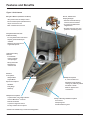
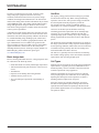
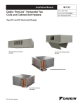
Daikin Thinline™ Horizontal Fan Coils are intended for use in
single zone applications . They are available in sizes from 200
to 1200 cfm . Figure 2 and Figure 3 describe the main features
of these units and can be referred to for component
placement . These units are available in two-pipe
configurations with one hydronic coil, with or without
electric heat for main or supplemental heating . They are also
available in four-pipe configurations with a primary coil and
a secondary reheat or preheat coil. A variety of factory-built
piping packages are available, either factory or field-installed.
Units are available with a variety of control options, including
MicroTech™ III controller board.
AHRI Certification
Agency Listed
Standard size units certified
in accordance with the Room
Fan-Coil Unit certification
program, which is based on
AHRI Standard 440.
A choice of motors, PSC or ECM, is available. Fan Coil units
can be provided with a fresh air damper option—manual or
automatic.
All standard units
All Canadian units
Figure 1: Nomenclature
FC H C - 1 02 A
Unit Type
FC = Fan Coil
FH = Cabinet Unit Heater
Unit Configuration
H= Horizontal
Cabinet Type
C = Cabinet
R = Recessed
H = Hideaway
Voltage
A = 115/60/1
E = 208-230/60/1
J = 277-265/60/1
Unit Size
02 = 200 CFM
03 = 300 CFM
04 = 400 CFM
06 = 600 CFM
08 = 800 CFM
10 = 1000 CFM
12 = 1200 CFM
Design Series — 1
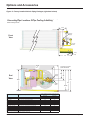
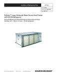
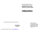
Figure 2: Model FCHH with return plenum
Return Plenum
Primary Coil
(Chilled Water Cooling)
2-, 3- or 4-row
Secondary Coil
(Hot Water or Steam Heating)
Standard or High Capacity
Catalog 724-2
Drain Pain
Galvanized or Stainless Steel
3
Features and Benefits
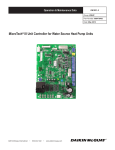
Features and Benefits
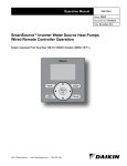
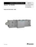
Figure 3: Unit features
Diverse, Flexible Valve
& Piping Packages
Mixing Box Modules (Automated or Manual)
•Two-position fresh air damper control
•Software selectable factorymounted, wired and tested
•Full economizer option (with MicroTech)
•Top or rear fresh air inlet
•Or, factory-assembled and
shipped loose
•Rear or bottom return air inlet
•Normally closed or open, twoposition or modulating valves
Easily Removable Drain Pan
& Motor Assembly
•For easy maintenance and service
•Sloped, galvanized drain pan
standard
•Stainless steel drain pan for
higher IAQ optional
Optional Secondary
Drain Pan
•Included with
factory-installed
valve packages
•Easily removable
•Galvanized or
stainless steel
Standard
Color Options
•Antique White
Multiple Coil Options
•Cupola White
•2, 3 or 4-row main coil
Special Color Options
•Off White
•Standard or High Capacity
heating coil, reheat or preheat
•Putty Beige
•Hot water or steam
•Soft Gray
•Same or opposite end
connections*
Multiple Control Options
•3-speed switch, low voltage interface
board or MicroTech ® controller
•Remote thermostat
•3-speed or staged fan control
•Factory-installed sensor options
Variety of Discharge and Return Options
•Duct collars
•Stamped grilles
•Double-deflection grilles
* Preheat coils available only in same-hand configuration
4
Catalog 724-2
Features and Benefits
Features and Benefits
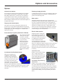
The ThinLine Advantage
ThinLine horizontal fan coils combine features most desired
in a fan coil by building owners, specifying engineers and
contractors alike. The result is a fan coil design that meets the
needs of all three.
For building owners
ThinLine fan coils offer quiet and energy efficient operation.
They fully comply with ASHRAE 62.1-2010 standards for
high indoor air quality. And they offer a range of control
options including BAS controls that can enhance occupant
comfort and reduce operating costs. These units are also easy
to maintain, with easy access to filters, fan motors and control
systems. Fully concealed, Recessed or Exposed type units are
available. Tamper-proof style cabinets are offered. A total of
five color options, both as standard and special requests are
available for a variety of decor styles.
For specifying engineers
ThinLine fan coils provide great versatility. A variety
of horizontal ceiling models are available with multiple
arrangements and configurations.
• Coil options include two-, three-, and four-row primary
coils to provide precise heating and cooling performance
for any requirement. Separate, single-row standard or
high capacity secondary heating coils (hot water or
steam) are available in reheat or preheat arrangements.
Preheat coils are also available with same or oppositeend coil connections.
• .
For contractors
ThinLine fan coils feature Quick Ship options for fast
delivery and a number of features that make installation fast
and simple.
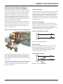
• Factory-mounted, wired and tested valve and piping
packages for quick hookup to the building piping to
reduce installation time. Packages can also be shipped
loose with the unit for quick and easy field installation.
Valve and piping packages are designed for entering
water temperature sampling. This eliminates the need
for inefficient bleed lines to sense automatic changeover
on two-pipe units.
• Factory-mounted and tested controls minimize field
setup. Depending on the option requested, controls can
be wired with a 24 VAC transformer to provide a singlesource power connection to the unit. Several options are
available for wall-mounted thermostats and unit or wallmounted sensors. All wall-mounted thermostat and zone
sensors require only low-voltage control wiring from the
device to the unit control box.
• Multiple convenient knockouts and easy bottom and
end panel removal for hookup of electrical and piping
connections minimizes field-labor time and cost.
• Opposite end connections minimize efforts for the
replacement or retrofit process. Easy fan deck removal
provides quick access for inspection, maintenance or
repair.
• Both the main drain pan and optional secondary drain
pan are easily accessed and removable for cleaning.
Field reversible for ease of installation in every situation.
• Discharge grille options include stamped or doubledeflection louvers. Open return or ducted return air is
available, as well as stamped louvers for cabinet type
units. Rear or bottom returns, front and bottom supply
locations are offered.
• Appearance options include cabinet units with a durable,
powder paint finish and decorative ceiling panels for
recessed units in Cupola White or Antique Ivory. Other
colors such as Off White, Putty Beige and Soft Gray are
available. Custom colors can be matched as a special
item. Tamper-proof units are a selectable option, with
special screw head that prevent unauthorized access to
unit interiors.
• Units are ETL and cETL listed. Performance is AHRI
certified.
Catalog 724-2
5
Options and Accessories
Options and Accessories
Model Configurations
Hideaway units model FCHH
open or duct collar option. Cabinets are made of heavyduty steel and insulated with ½" thick Tuf-Skin® fiber glass
insulation suitable for air stream applications. Optional ¼"
antimicrobial-treated closed-cell insulation is softwareselectable. Cabinets are of generous size allowing for all
necessary appurtenances, including factory-installed controls
and piping packages, to be covered and easily accessible.
Bottom panel is equipped with a large-size hinged door
providing easy access to components and simplifying
maintenance process. Units with bottom discharge use two
hinged doors and an enlarged bottom panel.
Recessed units model FCHR
Concealed above-ceiling type fan coils can be supplied with or
without factory-installed plenum. The low profile of a hideaway
unit without a plenum makes it a perfect fit for applications
where height is at a premium, for example drop-ceilings or
over-closet projects. The return plenum is provided with an
integral filter frame which is capable of carrying either 1"
throwaway filter (MERV4), 1" permanent steel-mesh washable
filter or higher efficiency filters to be used with ECM motors:
1" MERV8 and 1" MERV13 filters. Plenums may be supplied
with rear or bottom return openings. Return connections are
equipped with factory-installed duct collars. Open returns are
also available. Supply connections are located at the unit front
and equipped with duct collar for easy ducting. The plenums
are made of heavy-duty steel and insulated with ½" thick TufSkin® fiber glass insulation suitable for air stream applications.
Optional ¼" antimicrobial-treated closed-cell insulation is
software-selectable.
Cabinet units model FCHC
Fully- or partially recessed fan coils are available. Unpainted
galvanized-steel finish or painted cabinet units will be
supplied with a field-mounted fixed trim flange or floating
ceiling panel to provide smooth transition to drywall ceiling.
Recessed units with front discharge are provided with floating
panel capable of telescoping 1.5" in height. These ceiling
panels include bottom return with a filter frame and may be
provided for back returns (ducted or open) as well. The panels
are equipped with a large-size hinged door providing easy
access to components and simplifying maintenance process.
Units intended for use with bottom discharge will be supplied
in painted cabinets with fixed ceiling trim flanges coated in
paint of the same color as the unit.
.
Exposed ceiling type fan coils can be provided in a variety
of attractive cabinet options suitable for any décor style,
including 5 software-selectable paint colors. These fan coils
are ideal for hotels, apartments, colleges, dormitories, etc.
Rear and bottom return, front and bottom supply options
are available. Return opening with integral filter frame
may be provided in standard stamped louver option, open
return or even with a duct collar. Discharge opening is
offered with a stamped or double-deflection louver or with
6
Catalog 724-2
Options and Accessories
Options and Accessories
Options
Cabinet Color Options
Discharge (supply) Air Grille
.
A stamped-steel supply air grilles are standard for both front
and bottom discharge. Also available is a double deflection
grille for front discharge units.
Motor option
Tamper-proof Cabinet Option
This option can be factory-installed on cabinet units to
prevent access to unit controls and unauthorized removal of
cabinet panels. It includes torx head screws for cabinet panels.
Stamped grille for return and supply air is standard with
tamper-proof models.
Horizontal ThinLine fan coil units are equipped with
standard three-tap Permanently-Split Capacitor (PCS) motors
for 115/1/60, 208-230/1/60 and 277/1/60 volt applications.
Optional brushless DC Electronically Commutated Motors
(ECMs) are available for the above voltage ranges. These
motors are also used for high-static applications. All motors
are connected to a unit-mounted electric panel with QuickConnect fitting for ease of maintenance.
Electric heater options
Fresh Air Damper Options (Automatic or Manual)
The mixing box module
with top or rear fresh
air inlets is available
for concealed, recessed
or exposed units.
Mixing box control
can be automated or
manual. Automatic
options include a
2-position control or a
full economizer option
(MicroTech controller
only).
Single-point power connection
electric heaters are available for
the following applications: 1) as
total source of heat for the unit; 2)
as supplementary (intermediate)
source of heat between the
seasons. Dual power connections
are available when a motor and a
heater are of different voltage. The heater coils are fabricated
of Nickel-Chromium high-grade resistance wire and are
placed directly in front of the blower outlet. High limit
thermal cut-out protects the heater in the event of insufficient
air delivery.
Total electric heat
Condensate Overflow Switch Option
With proper mounting, the
condensate overflow switch
will detect water collecting in
the primary drain pan before an
overflow can occur. This is a N.C.
low voltage switch that opens
when water levels rise and closes
when water is no longer present.
For units without MicroTech controllers, the switch should be
field-wired to a controller to facilitate the fan and/or control
valve shut-down when condensate starts collecting in the
drain pan.
Catalog 724-2
Primary coil is used for cooling
only. A single-stage electric
heater provides total heat for the
system. Individual room control
can be provided for manual or
automatic changeover.
Intermediate (supplementary)
electric heat
Primary coil is used for cooling or heating depending on
the season and demand. In summer, while cold water is
circulating in the system the fan coil unit will be cooling the
space. In winter, the circulating hot water will make the fan
coil unit heat the space. Between seasons, when the space
control calls for heating, it will be provided by the electric
heater.
7
Options and Accessories
Control Options
Manual 4-Position Fan Switch
Several styles of the fourposition fan switch (Off,
High, Med, Low) are
available for unit-mount,
remote- or wall-mount. The
remote-mount option operates
on low-voltage or line-voltage
power and can be provided with a factory-mounted, low-voltage
interface board, which contains (3) 24-volt relays with linevoltage contactors and terminal connections. The transformer is
factory-installed and wired. The unit-mounted option operates
on line voltage.
• On-Off fan and On-Off valve cycle operation: The
thermostat cycles the fan from the manually-selected fan
speed to Off and it cycles the valves On and Off.
When the system switch is in the Off position, the fan coil
system, including the fan, is shut off.
Digital Thermostats
.
Sequence of operation
• Off: Fan is turned off. The two-position, motorized
fresh-air damper, when supplied, is closed.
• High, Medium, Low: Fan runs continuously at the
selected speed. The two-position, motorized fresh-air
damper, when supplied, is opened.
Remote-Mounted Thermostats
MT158 and MT168 Thermostat-Controllers with
Digital Display
Analog Thermostats
Series MT158 and MT168
microprocessor-based
thermostat controllers
combine a proportional
integral (PI) control algorithm
with adaptive logic.
MT155 Thermostat
The MT155 series thermostat
provides On-Off control for
low-voltage or line-voltage
valves and fan motors. It is
remote- mounted. Options
include manual or automatic
changeover and three-speed
fan control for continuous or
cycling fan operation.
Analog Thermostat with 3-Position Fan Switch
This option combines the
three-position fan switch
with an electronic analog
thermostat. For two-pipe
systems with a factory
installed valve package, it can
be provided with an automatic
switch (MTB-155) to change from heating, or cooling. Or
changeover can be a manual switch (MTA-155) .
Sequence of operation
Two standard control options are available:
• Continuous fan and On-Off valve cycle operation: The
thermostat cycles the valves On and Off. The fan runs
continuously at the manually selected fan speed.
8
Heating and cooling
outputs for the MT158 are
individually configurable for three-wire floating control
valves or On/Off valves in the Normally-Open (NO) or
Normally-Closed (NC) modes.
Heating and cooling outputs for the MT168 provide 0-10 Vdc or
4-20 mA. An integrated, three-speed fan control switch is linevoltage capable to allow direct connection to the fan motors.
A manual or automatic changeover is provided with remote
setback capability from a time clock or facility management
system. Features include a Fahrenheit or Celsius digital display
and built-in purge cycling which assists the controller to
determine if the system is supplying hot water or cooling.
Standard Control Mode
• On-off fan cycle operation and modulating (or On-Off)
valve operation. The controller cycles the fan from
the manually selected fan speed to Off. The controller
modulates the valves or, on the MT158, dip-switches can be
set to cycle the valves On and Off. Used for remote-mount
thermostats or with a remote room temperature sensor.
Catalog 724-2
Options and Accessories
T170 Thermostat with Digital Display
T180 Programmable Thermostat
Two thermostats are offered for
remote installation only: TA170
for three-speed fan control and
TB170 for staged fan operation.
Both thermostats are used for OnOff control of low- or line-voltage
valves with auto changeover. For
detailed information refer to IM 1152
Daikin Applied offers two
different 7-Day Programmable
Digital Heating/Cooling
Thermostat with constant
fan or Fan cycled, On/Off
Valve Control depending on
the fan speed control . The
thermostat interface contains
buttons for use in navigation to
accompanying menus/screens and for performing specific
operations . Detailed installation instructions and modes of
operation can be found in IM 1152
Table 1: Thermostat Summary Table
Thermostat Type
Model
Software Tabs
On/Off Switch with 3-speed Fan Switch with Hi/Med/Lo Settings and
Switched Auxiliary Connection
MTE-155
Accessories
2-Pole Dead-Band Auto-Changeover Thermostat with Manual On-Off System Switch
and Manual 3-Speed Fan Switch, On/Off Valve Control
MTB-155
Accessories
Thermostat with Manual Heat-Off-Cool System Switch and Manual 3-speed Fan
Switch, On/Off Valve Control
MTA-155
Accessories
Digital Thermostat 24 vac/120-277 vac with 3-speed Fan Control
(Continuous or Fan Cycle)
MTA-170
Accessories
Digital Thermostat with 7-Day Programmable, 24 vac/120-277 vac with 3-speed Fan
Control (Continuous or Fan Cycle)
MTA-180
Accessories
Digital Thermostat 24 vac/120-277 vac with Staged Fan (Continuous or Fan Cycle)
MTB-170
Accessories
Digital Thermostat with 7-Day Programmable, 24 vac/120-277 vac with 3-speed Fan
Control (Continuous or Fan Cycle)
MTB-180
Accessories
Digital Thermostat with Dead Band Auto-Changeover for Heating/Cooling.
On/Off or 3-wire Floating Valve Control and 3-speed Fan Switch
MTB-158
Accessories
Digital Thermostat with Dead Band Auto-Changeover for Heating/Cooling, On/Off,
and Manual 3-speed Fan Switch
MTA-158
Accessories
Digital Thermostat with Auto-Changeover, Dead-Band, 0-10 vDC Proportional
Modulating Valve Control.
MTB-168
Accessories
Digital Thermostat with Auto-Changeover, Dead-Band, 0-10 vDC Proportional
Modulating Valve Control, and Manual 3-speed Fan Switch
MTA-168
Accessories
*Can be field-mounted on units with Low Voltage Interface Boards, refer to IM1089
Low Voltage Interface Board
The Low-Voltage, Interface
Board (LV board) is used with
any remote (wall-mounted)
Daikin thermostat . With a fieldsupplied controller, it can also
be used with a BAS (Building
Automation System) control
where low voltage is needed to
operate a fan coil .
Catalog 724-2
The LV interface board includes:
• Three 24-volt relays with line voltage contactors to
operate fan motor speeds
• A factory wired and installed transformer
• Terminal connections for interfacing to:
• An optional wall-mounted thermostat
• Low-voltage actuators for heating and cooling valves
• A return air sensor
• A pipe temperature sensor for changeover from heating
to cooling on two-pipe systems
• An optional condensate overflow switch
9
Options and Accessories
MicroTech Controllers
ThinLine fan coils can
be provided with unitmounted MicroTech
controllers and multiple
unit- or room-mounted
sensors.
MicroTech controllers can
only be used with remote
room sensors (described
below) and not with remote
thermostats.
A MicroTech controller is
able to operate in either a stand-alone non-communicating
environment or a communicating environment. To
operate in a communicating environment, a board named
communication module, is installed on the unit controller.
There are two types of communication modules available
with MicroTech controllers: LonWorks and BACnet MSTP.
Unit controller sequences and controls: single- or multi-speed
fans, two-position hydronic cooling and heating valves,
floating three-wire hydronic cooling and heating valves,
electric heat, ventilation dampers or economizers.
Unit controllers and/or I-O expansion boards have inputs
for room or return temperatures, temperature setpoint
adjustments, fan speed switches, entering water temperatures,
discharge air temperatures, changeover auto switches, low
temperature detection, emergency shutdown detection,
condensate overflow detection, dirty air filter detection
and occupancy. All sensors are software selectable and the
controller is configured based on the selection.
Sensors
Remote-mounted Room Temperature
Sensor with Timed Override
The Basic Sensor provides simple room
temperature sensing all applications.
Unit status is provided through a
flashing LED located on the sensor
while timed tenant override and fault
reset are provided through the Override
button.
Room Temperature Sensor with Setpoint
Adjustable Module and Fan Speed Control
The Digitally Adjustable sensor
provides the ultimate of temperature
control and display, simple user
interface, alarm annunciation,
and alarm reset. The easy to ready
LCD clearly identifies the system
operating mode including occupied/
unoccupied mode, fan operation and
control, unit status, timed override
status, alarm annunciation, and
energy savings mode through a
series of recognizable icons. Tactile
response buttons initiate adjustments for temperature set
points, system mode, fan mode, occupancy, tenant override
and fault reset functions. The large numeric LCD will display
space temperature (°F or °C) with the corresponding setpoint
conditions. This sensor is designed for use with BACnet or
LonWorks applications. However, it can also be installed as a
standalone sensor using factory default set points.
Customer-Supplied Controls
Your Daikin Applied representative can work with engineers
and/or contractors to factory install and wire other
manufacturers’ DDC controllers on the fan coil . Contact your
local Daikin Applied sales representative for assistance with
your specific project.
10
Catalog 724-2
Options and Accessories
Factory Valve & Piping Packages
Factory valve and piping packages are available for both
two-pipe and four-pipe systems with either right or left hand
connections. Four-pipe systems can be configured with the
heating and cooling connections on the same or opposite
sides of the unit. Packages can be either factory-installed
or factory-assembled and shipped loose with the unit. All
factory-assembled packages are fully leak tested. Units are
also available without valve and piping packages in either a
right-hand or left-hand configurations.
Available Packages
Factory-installed packages are welded to the coil and wired
to the unit control box, MicroTech controller or LV Interface
Board. For field-installed packages, chilled and hot water
pipes are the only field connections required. Piping is 1/2"
nominal copper (5/8" OD).
Shut-Off Only Packages
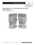
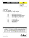
Figure 4: Four-pipe deluxe valve and piping package
All factory-installed valve packages are flexible, configurable
and fully software-selectable in our Daikin McQuayTools
selection program. Custom valve packages are available also.
Numerous piping packages are available to match design
configurations. Additional components can be added to meet
exact requirements, including P/T ports, unions, and flexible
stainless steel hoses.
Shut-Off Only piping packages provide interconnecting
copper piping and shut-off ball valves for ease in connecting
supply and return lines to the unit. Four-pipe packages
include a venting valve for the preheat or reheat coil. Primary
coils on all units have an integral venting valve.
Figure 5: Shut-Off Only Package
C
O
I
L
(See Figure 10 for components key)
Basic Packages
Basic valve and piping packages add control valves to the
Shut-Off Only package. All Daikin control valves are
factory-mounted in the supply water pipe. See Control
Valve Options on page 13 for more information on the
variety of control valves available .
Pre-determined field connection points are located for easy
access. The installing contractor can pre-pipe the building
water connections before the units arrive on the jobsite. A
label clearly identifies chilled and hot water connection points
on every unit.
All chilled water piping and components are located to allow
condensate to drain into the secondary drain pan supplied
with the valve package. Insulation of the factory piping
package is not required.
Catalog 724-2
Figure 6: Basic Package
C
O
I
L
(See Figure 10 for components key)
11
Options and Accessories
Enhanced Packages
Deluxe Packages
Enhanced valve and piping packages add a strainer to the
Basic package supply water pipe. The strainer is attached to
the supply water pipe at the coil connections. The strainer
body is cast brass construction with a stainless steel mesh that
is easy to remove for cleaning.
Deluxe valve and piping packages add a strainer to the
Premium package. The strainer is available with or without an
optional draining (blow-off) valve.
Figure 7: Enhanced Package
C
O
I
L
Figure 9: Deluxe Package
C
O
I
L
(See Figure 10 for components key)
(See Figure 10 for components key)
Premium Packages
Premium valve and piping packages replace the Basic
package a ball valve in the return line with a manual or
automatic circuit setter. The manual circuit setter is also
known as a manual flow control valve. The auto circuit setter
acts as both a flow setting device and a shut-off valve. It
allows water flow through the fan coil to be set quickly and
accurately. The circuit setter includes a cartridge within the
valve body that is sized to allow a specific flow rate through
the coil without any action required by a system piping
balancer.
P/T ports are included, which are used to measure the
temperature or pressure drop across the valve. This pressure
drop can be compared to factory supplied tables that relate the
pressure drop to a specific flow rate. The manual circuit setter
valve also has a memory stop so that the correct setting can
be found quickly.
Figure 8: Premium Package
C
O
I
L
Figure 10: Components Key for Schematics
Manual Shutoff Ball Valve: Water shut-off.
Handle rotates 90 degrees.
Manual Shutoff Ball Valve with Memory
Stop: Used on return line for limiting water
flow.
2-Way, N.C., On/Off Valve, Spring Return:
Turn On or Off water flow to the coil in
response to 24V or line voltage signal
3-Way, N.C., On/Off Valve, Spring
Return: Bypass water flow away from coil
in response to 24V or line voltage signal.
Includes fixed orifice for balancing.
2-Way Modulating Valve (3-wire or
proportional): Modulates water flow in
response to 24V signal.
3-Way Modulating Valve (3-wire or proportional): Modulates or bypass water flow
in response to 24V signal. Includes fixed
orifice for balancing.
PT Port: For connecting a pressure or
temperature gauge.
Y-Strainer: Removable screen filters out
small particles from supply line during normal system operation.
Manually Adjustable Circuit Setter with
Shutoff: Pressure-dependent, ball-type,
manual flow control.
Cartridge-Type, Auto-Fixed Circuit Setter:
Pressure-compensated, automatic fixed-flow
control.
(See Figure 10 for components key)
Union: For easy removal of piping from coil.
Bypass Balancing Valve: Adjustable
balancing of water flow through the bypass
circuit on a 3-way control valve.
Note: Daikin 3-way valves are equipped with a fixed balance orifice in the bypass
line, eliminating the need for a separate balancing valve
12
Catalog 724-2
Options and Accessories
Control Valve Options
Except for Shut-off Only packages, all valve and piping
packages include control valves for controlling water flow.
All Daikin control valves are factory assembled and mounted
in the supply water pipe downstream of the coil . Several
options are available:
Two-Way Modulating Valves
.
Two-Way/Two-Position Valves
.
Three-Way Modulating Valves
.
Three-Way Two-Position Valves
.
Selecting Correct Size Modulating Valves
Daikin McQuayTools software automatically selects the best
modulating valve size for the unit and coil being considered.
By combining the ARI performance data, the coil flow
rate and the DP across the water coil, the water coil Cv is
calculated and the best matching modulating port size is
selected. Valve and piping packages can easily be configured
and automatically selected using Daikin McQuayTools.
Catalog 724-2
13
Options and Accessories
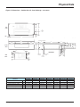
Figure 11: Factory-installed Valve & Piping Packages (right-hand shown)
Connecting
or Heating
ConnectingPipe
PipeLocations:
Locations: 2-Pipe
2-Pipe Cooling Only,
Right-hand
Deluxe
Package
shown
Deluxe
Package
shown, see schematic (page 2) for the list of components selected for this package
5.38
3.42
○
×
REFERENCE POINT
Primary
Supply
Front
View
Primary
Return
0.56‡
1.5†
7.0
20.25
B
A
† Overflow Connection
‡ Drain Connection
○
×
REFERENCE POINT
4.43
Primary
Supply
End
View
5.5
10.42
11.1
10.8
Primary
Return
10.58†
Primary Package Connections from Reference Point
(2- & 3-row Coil)
Name
Component Description
Supply (A)*
Return (B)*
Basic 2W
2Way control valve, shut-off valves
12.2
16.2
Basic 3W
3Way control valve, shut-off valves
12.2
17.0
Enhanced 2W
2Way control valve, shut-off valves, strainer
15.8
16.3
Enhanced 3W
3Way control valve, shut-off valves, strainer
15.8
17.0
Premium 2W, auto flow
2Way control valve, shut-off valves, auto flow-setter
12.3
15.8
Premium 2W, manual flow
2Way control valve, shut-off valves, manual flow-setter
12.3
16.6
Premium 3W, auto flow
3Way control valve, shut-off valves, auto flow-setter
12.2
14.8
Premium 3W, manual flow
3Way control valve, shut-off valves, manual flow-setter
12.2
15.6
Deluxe 2W, auto flow
2Way control valve, shut-off valves, strainer, auto flow-setter
15.8
15.8
Deluxe 2W, manual flow
2Way control valve, shut-off valves, strainer, manual flow-setter
15.8
16.6
Deluxe 3W, auto flow
3Way control valve, shut-off valves, strainer, auto flow-setter
12.2
14.8
Deluxe 3W, manual flow
3Way control valve, shut-off valves, strainer, manual flow-setter
12.2
15.6
NOTE: For 4-row Primary Coils add 1" to the dimensions A and B shown
14
Catalog 724-2
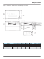
Options and Accessories
Connecting
Pipe
Locations:
4-Pipe
Cooling
and
Same-side Right-hand
Connecting
Pipe
Locations:
4-Pipe
Cooling
& Heating,
Heating Same-side,
Deluxe
Package
shown shown, see schematic (page 2) for the list of components selected for this package
Deluxe
Package
10.35
7.7
○
×
REFERENCE POINT
5.38
3.42
Primary
Supply
Secondary
Return
Primary
Return
Secondary
Supply
0.56‡
1.5†
7.0
Front View
† Overflow Connection
‡ Drain Connection
20.25
K
B
C
A
D
○
×
○
×
REFERENCE POINT
REFERENCE POINT
Primary
Supply
Secondary
Return
4.4
X
5.5
11.1
10.42
7.9
10.8
Primary
Return
10.58†
Secondary
Supply
Primary Piping End View
Name
Basic 2W
Basic 3W
Enhanced 2W
Enhanced 3W
Premium 2W, auto flow
Premium 2W, manual flow
Premium 3W, auto flow
Premium 3W, manual flow
Deluxe 2W, auto flow
Deluxe 2W, manual flow
Deluxe 3W, auto flow
Deluxe 3W, manual flow
Component Description
2Way control valve, shut-off valves
3Way control valve, shut-off valves
2Way control valve, shut-off valves, strainer
3Way control valve, shut-off valves, strainer
2Way control valve, shut-off valves, auto flow-setter
2Way control valve, shut-off valves, manual flow-setter
3Way control valve, shut-off valves, auto flow-setter
3Way control valve, shut-off valves, manual flow-setter
2Way control valve, shut-off valves, strainer, auto flow-setter
2Way control valve, shut-off valves, strainer, manual flow-setter
3Way control valve, shut-off valves, strainer, auto flow-setter
3Way control valve, shut-off valves, strainer, manual flow-setter
Secondary Piping End View
Primary Package
Connections from Reference
Point (2- & 3-row Coil)
Secondary Package
Length
Secondary Coil Connection
from Reference Point
Supply (A)*
Return (B)*
Return
(C)
Supply
(D)
Preheat
(K)
Reheat
(K)
High
Capacity
(X)
Standard
Capacity
(X)
12.2
12.2
15.8
15.8
12.3
12.3
12.2
12.2
15.8
15.8
12.2
12.2
16.2
17.0
16.3
17.0
15.8
16.6
14.8
15.6
15.8
16.6
14.8
15.6
6.5
9.0
6.5
9.0
6.1
10.6
5.1
9.6
6.1
10.6
5.1
9.6
7.1
7.1
10.7
10.7
7.1
7.1
7.1
7.1
10.7
10.7
10.7
10.7
4.53
1.03
0.8
2.8
NOTE: For 4-row Primary Coils add 1" to the dimensions A and B shown
Catalog 724-215
Unit Selection
Unit Selection
To achieve an efficient fan coil system, accurate system
design and proper equipment selection is necessary.
Variations, limitations/control of fan coil systems, design
conditions and design load calculations are not described in
detail in this catalog. More detailed information may be found
in the ASHRAE Guide. This catalog contains ARI-certified
ratings and application ratings for ThinLine fan coil units
from which a design engineer can make initial unit selections
to meet system requirements.
.
Unit Size
The capacity ratings presented in this catalog are provided
for initial unit selection only . Water cooling and heating
capacities, unit air flow, static pressure and glycol solutions
are all incorporated into the program to provide the
best possible selection . Consult your Daikin Applied
representative for a selection tailored to specific applications.
Unit sizes for the ideal system should be selected by
calculating peak load requirements due to unusually high
occupancy or severe climatic conditions and with fans
operating at high speed. Ordinary day-to-day cooling and
heating requirements are then achieved at low and medium
speeds.
The initial unit selection should be checked for air volume in
the design system and the cooling capacities checked against
actual operating conditions. While units selected on the basis
of sensible load will generally meet the total cooling load,
total load should be checked in all cases.
Basic design data
The unit size is generally selected on the basis of matching
the sensible cooling capacity of the unit with the calculated
requirements when operating at high speed.
Prior to selecting individual unit sizes, a design engineer must
fix or determine the following factors:
Coil Types
• Inside and outside wet and dry bulb design temperatures
• Total and sensible heat gains and losses of the area to be
served
• Ventilation air
• Properties of the heating and cooling medium
• Available electric power service
• Any special design requirements of the building or
system
16
Standard coils are designed to meet both cooling and heating
requirements in a typical system. Two additional levels of
enhanced primary coils are available to meet the total and
sensible requirements of any application.
Heating requirements for two-pipe systems are generally
met by employing the same water flow rate as cooling and
adjusting the entering hot water temperature to obtain a
matching unit heat output at low fan speed.
.
Catalog 724-2
Performance Data PSC
Performance Data PSC
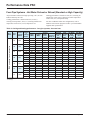
Two-Pipe Systems
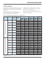
All performance measured on high speed tap, 115 V, at 0.05"
ESP for hideaway fan coils and 0.0" ESP for cabinet fan coils.
Cabinet units were tested with bottom return/front discharge
configurations.
Cooling performance is based on 80/67°F (27/19°C)
entering air temperature, 45°F (7°C) entering chilled water
temperature with a 10°F (5.5°C) temperature rise.
Heating performance is based on 70°F (21°C) entering air
temperature, 180°F (82°C) entering hot water temperature
with a 30°F (17°C) temperature drop.
For other conditions and/or unit configurations, refer to
Daikin Tools™ selection program or talk to your local Daikin
Applied sales representative .
Table 2: Cooling and heating performance - two-pipe systems
FCHC cabinet (bottom return/front discharge)
FCHH no plenum, free discharge fan
Unit Model
Unit Size
Nominal Air
Flow
SCFM
02
200
03
300
04
400
06
600
08
800
10
1000
12
1200
02
200
03
300
04
400
06
600
08
800
10
1000
12
1200
Number
Of Primary
Rows
2
3
4
2
3
4
2
3
4
2
3
4
2
3
4
2
3
4
2
3
4
2
3
4
2
3
4
2
3
4
2
3
4
2
3
4
2
3
4
2
3
4
Cooling
Performance
Total,
MBH
5.1
8.9
10.8
5.5
10.7
12.8
8.3
13.9
16.0
14.9
20.4
22.5
17.9
23.6
25.7
27.5
34.7
38.9
35.6
45.2
50.7
5.0
8.5
10.3
5.5
10.6
12.6
8.0
13.4
15.4
14.3
19.7
21.7
16.5
21.5
23.1
25.0
30.8
34.0
32.0
39.5
43.7
Sensible,
MBH
4.7
7.0
7.7
5.1
8.5
9.3
7.9
10.6
11.1
12.9
15.4
16.0
15.0
17.6
18.1
22.5
26.1
27.1
29.1
33.7
34.4
4.6
6.7
7.3
5.1
8.3
9.1
7.6
10.2
10.7
12.4
14.9
15.4
13.6
15.8
16.1
20.0
22.8
23.4
25.5
28.9
29.2
Heating
Performance
Chilled
Water Flow
CW
Pressure
Drop
MBH
GPM
Ft
21.7
28.1
29.3
25.0
32.9
35.0
31.9
40.5
42.7
50.4
63.8
67.8
57.4
71.4
74.5
84.4
100.6
107.6
102.2
124.1
134.8
20.9
27.1
28.1
24.7
32.5
34.5
30.9
39.2
41.2
48.9
61.6
65.2
52.3
64.2
66.3
75.1
88.4
92.8
89.8
107.2
114.6
1.0
1.8
2.2
1.1
2.2
2.6
1.7
2.8
3.2
3.0
4.1
4.5
3.6
4.7
5.2
5.5
7.0
7.8
7.1
9.1
10.1
1.0
1.7
2.1
1.1
2.1
2.5
1.6
2.7
3.1
2.9
4.0
4.4
3.3
4.3
4.6
5.0
6.1
6.8
6.4
7.9
8.7
0.2
1.0
1.9
0.3
1.3
2.4
0.6
2.4
4.1
2.3
6.1
9.5
3.5
8.4
13.2
8.8
13.5
23.9
15.9
26.6
49.4
0.2
0.9
1.7
0.3
1.3
2.4
0.6
2.3
3.9
2.1
5.8
8.9
3.0
7.2
10.9
7.4
9.9
17.0
13.2
19.6
33.9
1. 115/1/60 PSC motor at high speed
2. FCHH (without plenum) at 0.05” ESP
3. Free Discharge
Catalog 724-2
17
Performance Data PSC
Performance Data PSC
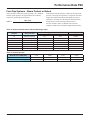
Four-Pipe Systems - Hot Water Preheat or Reheat (Standard or High Capacity)
All performance measured on high speed tap, 115 V, at 0.05"
ESP for hideaway fan coils.
Cooling performance is based on 80/67°F (27/19°C)
entering air temperature, 45°F (7°C) entering chilled water
temperature with a 10°F (5.5°C) temperature rise.
Heating performance is based on 70°F (21°C) entering air
temperature, 180°F (82°C) entering hot water temperature
with a 30°F (17°C) temperature drop.
For other conditions and/or unit configurations, refer to
Daikin Tools selection program or talk to your local Daikin
Applied sales representative .
Table 3: Cooling and heating performance - four-pipe systems, hot water heat
FCHH no plenum, free discharge fan
Unit
Model
Unit
Size
Nominal Number
of
Air Flow Primary
SCFM
Rows
02
200
03
300
04
400
06
600
08
800
10
1000
12
1200
2
3
4
2
3
4
2
3
4
2
3
4
2
3
4
2
3
4
2
3
4
Total,
MBH
4.9
8.3
10.3
5.4
10.1
12.5
7.6
13.1
15.3
14.0
19.4
21.6
17.0
22.5
24.7
26.2
33.1
37.5
34.0
43.0
48.8
Cooling Performance
Heating Performance
Chilled
Standard
High
Hot Water Hot Water
CW
Sensible,
Water Pressure
Capacity Capacity
Flow
Pressure
MBH
Flow
Coil,
Coil,
(Hi Cap),
Drop
Drop,
Ft
GPM
MBH
MBH
GPM
(Hi Cap), Ft
4.5
1.0
0.2
8.3
11.9
0.8
1.7
6.5
1.7
0.9
8.1
11.6
0.8
1.6
7.3
2.1
1.7
7.9
11.4
0.8
1.6
5.0
1.1
0.3
9.0
13.0
0.9
1.9
8.0
2.0
1.2
8.8
12.7
0.9
1.9
8.9
2.5
2.4
8.6
12.5
0.8
1.8
7.3
1.5
0.6
12.6
19.5
1.3
5.5
10.0
2.6
2.2
12.2
19.1
1.3
5.3
10.6
3.1
3.9
11.9
18.7
1.3
5.1
12.1
2.8
2.2
19.1
28.4
1.9
13.1
14.6
3.9
5.6
18.6
27.8
1.9
12.6
15.3
4.3
8.8
18.1
27.3
1.8
12.2
14.1
3.4
3.2
21.6
32.6
2.2
17.4
16.6
4.5
7.7
21.0
31.9
2.1
16.8
17.3
5.0
12.3
20.4
31.3
2.1
16.2
21.2
5.3
8.1
34.6
43.8
2.9
37.6
24.7
6.6
12.0
33.7
42.9
2.9
36.2
26.0
7.5
21.7
32.9
42.0
2.8
34.4
27.5
6.8
14.7
41.6
59.0
4.0
73.6
31.8
8.6
23.2
40.5
57.8
3.9
71.1
33.0
9.8
44.9
39.5
56.7
3.8
68.8
115/1/60 PSC motor at High speed setting
FCHH (w/o plenum) at 0.05” ESP
Free discharge
18
Catalog 724-2
Performance Data PSC
Four-Pipe Systems - Steam Preheat or Reheat
All performance measured on high speed tap, 115 V. Medium
and low-speed capacities are approximately 88% and 68%
respectively of the high-speed capacity.
Q/ITD =
MBh (kW)
Saturated steam temp – Entering air temp
To determine heating capacities at different entering steam
pressure or entering air temperature, compute the new Inlet
Temperature Differential (ITD) and multiply it by the Q/
ITD shown. See Table 5 to determine the saturated steam
temperatures at various entering steam pressures.
.
Table 4: Steam coil performance with free-discharge motor
Unit Size
Steam Coil Size
02
03
04
06
08
10
12
Standard Capacity
Standard Capacity
Standard Capacity
Standard Capacity
Standard Capacity
Standard Capacity
Standard Capacity
Heating Capacity MBH (kW)
2 PSIG (115 kPa)
5 PSIG (136 kPa)
15.1
16.2
16.4
17.6
23.6
22.0
34.7
27.9
29.1
38.4
32.1
44.2
41.5
59.5
Q / ITD @ 2 PSIG
MBH / °F
0.0952
0.1034
0.1386
0.1756
0.1827
0.2019
0.2610
Table 5: Steam properties
Steam Pressure PSIG (kPa)
2 (13)
3 (20)
4 (27)
5 (34)
Sat. Steam Temp. ºF (ºC)
219 (104)
222 (106)
224 (107)
227 (108)
Latent Heat Btu/Lb (kJ/kg)
966 (2245)
964 (2242)
962 (2239)
961 (2233)
Catalog 724-2
19
Performance Data PSC
Air Volume Capacity Data
.
Air volumes shown in the table are measured with a dry coil
at the motor speeds indicated with 115v/60/1 electrical power,
with a 1" throwaway filter installed, and with a rear return/
front discharge cabinet unit configuration.
Table 6: Air volume at various fan speeds PSC motors, SCFM
Unit
model
Unit size
02
FCHH no plenum, free discharge fan
03
04
06
08
10
12
02
FCHH w/ plenum, FCHC, FCHR
03
04
06
08
10
12
20
Number
of primary
rows
0.00”
0.05”
High Speed CFM at External Static
0.10”
0.15”
0.20”
0.25”
0.30”
CFM at 0.0” ESP and Fan Speed
High
Med
2
364
337
303
271
229
170
111
364
301
239
3
343
318
286
256
216
160
105
343
284
225
Low
4
321
298
268
240
202
150
98
321
266
211
2
435
418
403
385
366
337
297
435
285
197
3
410
394
380
363
345
318
280
410
269
186
4
384
369
356
340
323
298
262
384
252
174
2
510
472
432
388
338
264
180
510
401
280
3
481
445
407
366
319
249
170
481
378
264
4
451
417
381
343
299
233
159
451
354
247
2
779
722
661
586
520
438
318
779
612
460
3
734
681
623
552
490
413
300
734
577
434
4
688
638
584
517
459
387
281
688
541
406
2
844
783
765
707
639
554
439
844
643
475
3
795
739
722
667
602
523
414
795
606
448
4
745
692
676
625
564
490
388
745
568
420
2
1226
1199
1102
992
867
725
547
1226
951
694
3
1156
1131
1042
935
817
684
516
1156
897
655
4
1083
1059
965
876
766
641
483
1083
841
614
2
1610
1515
1410
1223
1102
942
707
1610
1249
911
3
1518
1428
1326
1153
1039
888
666
1518
1178
859
4
1422
1338
1244
1080
973
832
624
1422
1104
805
2
303
271
229
170
111
74
0
303
250
200
3
286
256
216
160
105
55
0
286
235
183
4
268
240
202
150
98
0
0
268
210
160
2
390
366
337
297
280
239
198
390
229
134
123
3
365
345
318
280
255
210
165
365
210
4
344
323
298
262
246
195
159
344
190
111
2
440
388
338
264
210
134
50
440
346
230
3
413
366
319
249
189
119
0
413
326
217
4
389
343
299
233
170
105
0
389
305
202
2
661
586
520
438
366
267
160
661
532
403
3
623
552
490
413
345
251
0
623
489
370
334
4
584
517
459
387
318
228
0
584
442
2
765
707
639
554
439
375
261
765
602
430
3
722
667
602
523
414
347
0
722
576
398
4
676
625
564
490
388
305
0
676
530
368
2
1102
992
906
772
617
442
246
1085
884
621
3
1042
935
854
725
582
417
0
998
772
569
4
965
876
795
675
530
380
0
902
701
516
2
1410
1223
1102
942
707
602
385
1412
1134
855
3
1326
1153
1039
888
666
515
0
1332
1075
787
4
1244
1080
973
832
624
498
0
1248
1000
710
Catalog 724-2
Performance Data ECM
Performance Data ECM
Performance Cooling and Heating – 2- and 4- Pipe
Air volumes shown in the table are measured at the motor
speeds indicated with 115v/60/1 electrical power, with a 1"
throwaway filter installed, and with a stamped discharge
grille on a horizontal cabinet unit or a discharge duct collar on
a hideaway unit at approximately 0.05 inch of pressure drop.
Cooling performance is based on 80/67°F (27/19°C)
entering air temperature, 45°F (7°C) entering chilled water
temperature with a 10°F (5.5°C) temperature rise.
Heating performance is based on 70°F (21°C) entering air
temperature, 180°F (82°C) entering hot water temperature
with a 30°F (17°C) temperature drop.
For other conditions and/or unit configurations, refer to
Daikin Tools selection program or talk to your local Daikin
Applied sales representative .
Table 7: Air volume at various fan speeds ECM motors, SCFM
Unit Size
Air Flow1
SCFM
02
329
03
393
04
459
06
670
08
770
10
1124
12
1464
FCHH, FCHC, FCHR any configuration
Unit
Model
Number
of Primary
Rows
2
3
4
2
3
4
2
3
4
2
3
4
2
3
4
2
3
4
2
3
4
Cooling Performance
Total,
MBH
Sensible,
MBH
Primary
Coil, MBH
5.1
9.6
12.5
5.5
11.1
14.3
8.3
14.6
18.1
12.5
20.8
24.8
17.8
24.8
29.2
27.1
36.0
43.7
35.4
47.5
57.5
4.7
7.5
9.0
5.1
8.8
10.5
7.9
11.3
12.9
10.6
15.8
17.8
14.8
18.6
20.8
22.1
27.2
30.9
28.9
35.7
39.5
21.2
28.6
31.7
23.9
32.7
36.6
31.0
41.1
45.9
57.1
62.9
70.2
61.8
72.2
79.6
88.6
101.2
114.1
107.6
126.4
144.7
Heating Performance
Secondary Std Secondary High
Capacity Coil,
Capacity Coil,
MBH
MBH
8.4
12.2
8.9
13.1
12.6
19.9
17.3
26
21.5
33.2
34.4
44.4
41.6
60.2
1. ECM motor at High speed setting, standard MERV 4 filter, any external static pressure up to 0.5"
Table 8: Air volume for units with ECM at all configurations and external static pressures up to 0.5"
Size
Super High
High*
Medium*
Low*
02
362
329
195
115
Super Low
93
03
432
393
236
165
133
04
505
459
346
260
238
06
737
670
550
388
345
08
847
770
630
444
404
10
1236
1124
865
622
490
12
1610
1464
1027
701
632
* Standard speed setting from the factory. Super High setting is 10% higher than High. Super Low setting is 10% lower than Low.
Catalog 724-2
21
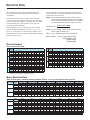
Electrical Data
Electrical Data
MCA (Minimum Circuit Ampacity), MOP (Maximum
Overcurrent Protection) or MFS (Maximum Fuze Size)
Calculations
HACR (Heating, Air-Conditioning and Refrigeration) type
circuit breakers are required in the branch circuit wiring for
all fan coils with electric heat.
The minimum circuit ampacity (MCA) is the minimum
wire size required for a field-wired product. The maximum
overcurrent protection (MOP), or maximum fuse size (MFS)
is the maximum fuse or circuit breaker size required to
properly protect the equipment.
NOTE: MCA and MOP ratings are based on the unit and
electric heat power supply having the same voltage. If
the electric heat power supply is different, a separate
circuit breaker may be required. Follow local codes.
Select a standard fuse size or HACR type circuit breaker
equal to the MOP. Standard Fuse Sizes are: 15, 20, 25, 30,
35, 40, 45, 50, 60 amps. Use the next larger standard size if
the MOP does not equal a standard size. See Table 8 through
Table 10 for motor FLAs.
Heater Amps = (Heater kW × 1000)
Heater Voltage
NOTE: Use 120V heater voltage for 115V units. Use 240V
heater voltage for 230V units.
MCA = 1.25 × (heater amps + all motor FLAs)
MOP or MFS = (2.25 x Largest Motor FLA)
+ Second Motor FLA
+ Heater Amps
[If Applicable]
Electric Heaters
Table 9: Electric heat kW*
Unit
Unit
Size Voltage
02
03
04
06
Unit
Unit
Size Voltage
115
230
08
277
208†
115
230
10
277
208†
115
230
12
277
208†
kW
115
1.0
1.5
2.0
230
277
208†
115
230
277
208†
115
230
277
208†
115
230
277
208†
1.0
1.0
0.8
1.0
1.0
1.0
0.8
1.5
1.5
1.2
1.5
1.5
1.5
1.2
2.0
2.0
1.6
2.0
2.0
2.0
1.6
2.0
2.0
2.0
1.6
2.0
2.5
2.5
2.5
2.0
2.5
2.5
2.5
2.0
2.5
2.5
2.5
2.0
3.0
3.0
3.0
2.5
3.0
4.0
4.0
3.3
5.0
5.0
4.1
kW
2.0
3.0
2.5
2.5
2.0
2.0
2.5
4.0
4.0
3.3
3.0
3.0
3.0
2.5
3.0
3.0
3.0
2.5
6.0
6.0
4.9
7.0
7.0
5.7
5.0
5.0
4.1
6.0
6.0
4.9
7.0
7.0
5.7
5.0
5.0
4.1
6.0
6.0
4.9
8.0
8.0
6.5
10.0
6.0
6.0
4.9
Note: *Electric heat MBh = (Heater kW) x(3.413)
† 208/1/60 V heater capacity is derated from 230/1/60
Motor Electrical Data
Table 10: PSC motor; hideaway plenum, standard TA filter; 3 row coil; 0.05 external static pressure
Motor Voltage
115
230
277
Motor
Speed
High
Medium
Low
High
Medium
Low
High
Medium
Low
Amps
0.596
0.49
0.381
0.3
0.247
0.2
0.303
0.228
0.177
Size 02
Size 03
Watts RPM Amps Watts
65.5
951 1.175
129
52.6
856 0.726
77.4
39.5
780
0.49
50.2
66
908 0.548 123.4
56.5
825 0.323
74
46
704 0.211
46.2
65.1
988 0.431 110.1
57.2
866
0.24
65.5
47.3
743 0.152
42.2
RPM Amps
1190 0.747
851 0.602
633 0.450
1152 0.372
830 0.309
628 0.251
1121 0.348
838 0.259
651 0.196
Size 04
Size 06
Watts RPM Amps Watts
79.2
928
1.45
147
62.25 785
1.05
103.1
43.95 640
0.87
82
86.2
909 0.657 150.6
70.8
750 0.449 101.5
55.9
628 0.358
76.5
82.3
885 0.513 142.4
67.6
762 0.371 101.6
53.6
650 0.302
81.9
RPM Amps
1080 1.48
888
1.13
734
0.91
1096 0.69
950
0.5
777
0.38
1091 0.54
945
0.39
796
0.31
Size 08
Watts
150
111
83
158
108
77
151
106
82
RPM Amps
1072 2.53
799
1.89
674
1.63
1085 1.19
887 0.814
720 0.663
1082 0.936
877
0.66
737 0.562
Size 10
Watts
263
185
154
269
180.1
142
258
178.5
150
RPM Amps
1119 2.965
997 2.218
856 1.833
1128 1.306
1024 0.86
840
0.69
1124 0.997
1014 0.713
891 0.625
Size 12
Watts
310.7
222.1
172.9
297.7
195
154
280
199
166
RPM
1068
840
660
1105
969
844
1112
970
784
Size 12
Watts
321
208
157
321
208
157
321
208
157
RPM
1460
1331
1260
1460
1331
1260
1460
1331
1260
Table 11: ECM motor; hideaway plenum, standard TA filter; 3 row coil; 0.30 external static pressure
Motor Voltage
115
230
277
22
Motor
Speed
High
Medium
Low
High
Medium
Low
High
Medium
Low
Amps
1.20
0.94
0.70
0.60
0.47
0.35
0.50
0.39
0.29
Size 02
Watts
65
46
35
65
46
35
65
46
35
RPM Amps
1258 1.42
1158 0.11
1099 0.86
1258 0.71
1158 0.55
1099 0.43
1258 0.59
1158 0.46
1099 0.36
Size 03
Watts
71.8
52
38
71.8
52
38
71.8
52
38
RPM Amps
1294 1.64
1240 1.14
1086 0.90
1294 0.82
1240 0.57
1086 0.45
1294 0.68
1240 0.47
1086 0.37
Size 04
Watts
89
62
47
89
62
47
89
62
47
RPM Amps
1269 2.46
1155 1.74
1106 1.14
1269 1.23
1155 0.87
1106 0.58
1269 1.02
1155 0.72
1106 0.48
Size 06
Watts
156
99
67
156
99
67
156
99
67
RPM Amps
1363 2.92
1220 2.24
1145 1.80
1363 1.46
1220 1.12
1145 0.90
1363 1.21
1220 0.93
1145 0.75
Size 08
Watts
196
152
119
196
152
119
196
152
119
RPM Amps
1456 3.72
1323 2.66
1263 2.00
1456 1.86
1323 1.33
1263 1.00
1456 1.54
1323 1.10
1263 0.83
Size 10
Watts
255
176
126
255
176
126
255
176
126
RPM Amps
1407 4.54
1294 3.12
1159 2.40
1407 2.27
1294 1.56
1159 1.20
1407 1.88
1294 1.30
1159 1.00
Catalog 724-2
Physical Data
Physical Data
Unit Data
Table 12: Physical data: coils, fans, motors and filters
Primary Coil Data
Face Area, ft2 (cm2)
Size 02
Size 03
Size 04
Size 06
Size 08
Size 10
Size 12
1.08 (1004)
1.08 (1004)
1.43(1323)
2.11(1962)
2.46(2281)
3.14(2917)
3.83(3559)
12 (4.7)
12 (4.7)
12 (4.7)
12 (4.7)
12 (4.7)
12 (4.7)
12 (4.7)
Fins/inch (cm)
Connection Size
1/2" Nominal Copper (5/8" OD)
Coil Dimensions
2-Row
L × D × H, in (cm)
17.3 × 1.7 × 9
(43.9 × 4.4 × 22.9)
17.3 × 1.7 × 9
(43.9 × 4.4 × 22.9)
22.8 × 1.7 × 9
(57.9 × 4.4 × 22.9)
33.8 × 1.7 × 9
(85.9 × 4.4 × 22.9)
39.3 × 1.7 × 9
(99.8 × 4.4 × 22.9)
50.2 × 1.7 × 9
(127.6 × 4.4 × 22.9)
61.3 × 1.7 × 9
(155.7 × 4.4 × 22.9)
3-Row
L × D × H, in (cm)
17.3 × 2.6 × 9
(43.9 × 6.6 × 22.9)
17.3 × 2.6 × 9
(43.9 × 6.6 × 22.9)
22.8 × 2.6 × 9
(57.9 × 6.6 × 22.9)
33.8 × 2.6 × 9
(85.9 × 6.6 × 22.9)
39.3 × 2.6 × 9
(99.8 × 6.6 × 22.9)
50.2 × 2.6 × 9
(127.6 × 6.6 × 22.9)
61.3 × 2.6 × 9
(155.7 × 6.6 × 22.9)
4-Row
L × D × H, in (cm)
17.3 × 1.7 × 9
(43.9 × 8.8 × 22.9)
17.3 × 3.5 × 9
(43.9 × 8.8 × 22.9)
22.8 × 3.5 × 9
(57.9 × 8.8 × 22.9)
33.8 × 3.5 × 9
(85.9 × 8.8 × 22.9)
39.3 × 3.5 × 9
(99.8 × 8.8 × 22.9)
50.2 × 3.5 × 9
(127.6 × 8.8 × 22.9)
61.3 × 3.5 × 9
(155.7 × 8.8 × 22.9)
2-Row
0.19 (0.7)
0.19 (0.7)
0.24(.9)
0.32(1.2)
0.37(1.4)
0.46(1.7)
0.55(2.1)
3-Row
0.26 (1.0)
0.26 (1.0)
0.32(1.2)
0.45(1.7)
0.52(2.0)
0.64(2.4)
0.77(2.9)
4-Row
0.34 (1.3)
0.34 (1.3)
0.43(1.6
0.61(2.3)
0.70(2.6)
0.87(3.3)
1.05(4.0)
2.44(2267)
Coil Volume, Gal (Liters)
Secondary Coil Data: 1-Row Standard Capacity, Hot Water or Steam
Face Area, ft2 (cm2)
0.61(567)
0.61(567)
0.84(780.1)
1.3(1208)
1.5(1421)
1.99(1845)
12 (4.7)
12 (4.7)
12 (4.7)
12 (4.7)
12 (4.7)
12 (4.7)
12 (4.7)
14.7 × .86 × 6
(37.3 × 2.2 × 15.2)
14.7 × .86 × 6
(37.3 × 2.2 × 15.2)
20.2 × .86 × 6
(51.3 × 2.2 × 22.9)
31.2 × .86 × 6
(79.2 × 2.2 × 22.9)
36.7 × .86 × 6
(93.2 × 2.2 × 22.9)
47.7 × .86 × 6
(121.1 × 2.2 × 22.9)
58.7 × .86 × 6 (149.0
× 2.2 × 22.9)
0.06 (0.23)
0.06 (0.23)
0.08 (0.30)
0.11 (0.42)
0.12 (0.45)
0.15 (0.57)
0.18 (0.70)
3.26 (3029)
Fins/inch (cm)
L × D × H, in (cm)
Connection Size
1/2" Nominal Copper (5/8" OD)
Connection Size
Volume, Gal (Liters)
Secondary Coil Data: 1-Row High Capacity, Hot Water or Steam
Face Area, ft2 (cm2)
0.82 (762)
0.82 (762)
1.26 (1171)
1.73 (1607)
2.04 (1895)
2.65 (2460)
12 (4.7)
12 (4.7)
12 (4.7)
12 (4.7)
12 (4.7)
12 (4.7)
12 (4.7)
14.7 × .86 × 8
(37.3 × 2.2 × 20.3)
14.7 × .86 × 8
(37.3 × 2.2 × 20.3)
20.2 × .86 × 8
(51.3 × 2.2 × 22.9)
31.2 × .86 × 8
(79.2 × 2.2 × 22.9)
36.7 × .86 × 8
(93.2 × 2.2 × 22.9)
47.7 × .86 × 8
(121.1 × 2.2 × 22.9)
58.7 × .86 × 8
(149.0 × 2.2 × 22.9)
0.08 (0.30)
0.08 (0.30)
0.11 (0.42)
0.14 (0.53)
0.16 (0.61)
0.20 (0.76)
0.24 (0.92)
Fan Quantity
1
1
2
2
2
4
4
Motor Quantity
1
1
1
1
1
2
2
1
1
1
1
1
2
2
Hideaway cm
L × D × H, in. ()
10.50 × 1.00 × 8.75
(26.6 × 2.5 × 22.2)
10.50 × 1.00 × 8.75
(26.6 × × 2.5 × 22.2)
16.00 × 1.00 × 8.75
(40.6 × 2.5 × 22.2)
27.21 × 1.00 × 8.75
(69.1 × 2.5 × 22.2)
32.71 × 1.00 × 8.75
(83.1 × 2.5 × 22.2)
21.81 × 1.00 × 8.75
(55.4 × 2.5 × 22.2)
27.31 × 1.00 × 8.75
(69.3 × 2.5 × 22.2)
Cabinet
L × D × H, in. (cm)
15.63 × 1.00 × 10.89
(39.7 × 2.5 × 27.6)
15.63 × 1.00 × 10.89
(39.7 × 2.5 × 27.6)
21.00 × 1.00 × 10.89
(53.3 × 2.5 × 27.6)
32.13 × 1.00 × 10.89
(81.6 × 2.5 × 27.6)
39.25 × 1.00 × 10.89
(81.7 × 2.5 × 27.6)
24.38 × 1.00 × 10.89
(61.9 × 2.5 × 27.6)
30.00 × 1.00 × 10.89
(76.2 × 2.5 × 27.6)
Fins/inch (cm)
L × D × H, in (cm)
Connection Size
Volume, Gal (Liters)
Fan/Motor Data
Filter Data
1" (25.4 cm) Media
Throwaway (MERV 4), MERV 7*, MERV 13* and Aluminum Washable
Quantity
* For use with ECM only
Table 13: Dry weights - lbs (kg)*
Unit Size
Unit Type
S02
S03
S04
S06
S08
S10
S12
FCHC/FCHR
108 (49)
110 (50)
124 (56)
139 (63)
151 (69)
184 (84)
196 (89)
FCHH
30 (14)
33 (15)
35 (16)
45 (20)
55 (25)
62 (28)
65 (30)
Note: *Approximate dry weights do not include plenums, valve packages, hot water coils, electric heaters or other options.
Catalog 724-2
23
Physical Data
Physical Data
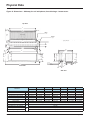
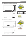
Unit Dimensions
Figure 12: Dimensions – Hideaway fan coil, front discharge – free return
Reheat coil shown
Top View
5.01
(4) Mounting
Holes
Secondary Drain Pan (1)
⅜" × ⅝"
Control
Box
⅝" O.D. Coil
Connections
(Typical)
NOTES:
1.0
C
(1) Secondary drain pan is only supplied with factory-provided
piping packages
6.0
○
×
REFERENCE POINT
F
D
0.5
H
0.64
2.49
4.35
3.4
B
15.28
0.68
1.62
REFERENCE POINT
REFERENCE POINT
○
×
○
×
9.25
6.75
8.08
9.47
9.42
9.86
5.21
1.5
A
Front View
Dimension
0.75" O.D.
Drain Connection
Side View
S02
S03
S04
S06
S08
S10
S12
inch (mm)
inch (mm)
inch (mm)
inch (mm)
inch (mm)
inch (mm)
inch (mm)
Overall Unit Width
A
28.48 (723)
28.48 (723)
33.98 (863)
44.98 (1142)
50.48 (12.82)
61.48 (1562)
72.48 (1841)
Chassis Width
B
20.63 (524)
20.63 (524)
26.13 (664)
37.13 (943)
42.63 (1083)
53.63 (1362)
64.63 (1641)
Mounting Hole Distance (Rear)
C
18.64 (473)
18.64 (473)
24.14 (613)
35.14 (892)
40.64 (1032)
51.64 (1312)
62.44 (1702)
Mounting Slot Location (Front)
D
19.35 (491)
19.35 (491)
24.85 (631)
35.85 (911)
41.35 (1050)
52.35 (1330)
63.35 (1609)
Discharge Opening - Width
F
17.39 (442)
17.39 (442)
22.84 (581)
33.89 (867)
39.39 (1000)
50.39 (1280)
61.39 (1559)
Primary Coil Location
H
Secondary Coil - Standard Capacity
Secondary Coil - High Capacity
Secondary Coil - Standard Capacity
Secondary Coil - High Capacity
24
0.5" O.D.
Overflow Connection
3.11
L
K
1.81 (46) for 2- or 3-row primary coil; 2.81 (71) for 4-row primary coil
2.86 (73)
0.86 (22)
5.0 (127)
7.0 (178)
Catalog 724-2
Physical Data
Figure 13: Dimensions – Hideaway fan coil with plenum, front discharge – rear return
Top View
G
5.01
(4) Mounting
Holes
Secondary Drain Pan (1)
⅜" × ⅝"
Control
Box
⅝" O.D. Coil
Connections
(Typical)
NOTES:
1.0
C
(1) Secondary drain pan is only supplied with factory-provided
piping packages
(2) For units without mixing box
6.0
○
×
REFERENCE POINT
F
D
0.5
H
0.64
21.5 (2)
2.49
20.2 (2)
4.35
5.4
B
17.3 (2)
0.68
1.62
REFERENCE POINT
REFERENCE POINT
○
×
○
×
9.25
9.47
8.8
6.75
8.08
9.88
9.42
9.86
5.21
1.5
A
0.5" O.D.
Overflow Connection
3.11
Front View
Dimension
0.75" O.D.
Drain Connection
Side View
S02
S03
S04
S06
S08
S10
S12
inch (mm)
inch (mm)
inch (mm)
inch (mm)
inch (mm)
inch (mm)
inch (mm)
Overall Unit Width
A
30.48 (771)
30.48 (771)
35.98 (944)
46.98 (1193)
52.48 (1333)
63.48 (1612)
74.48 (1892)
Chassis Width
B
20.63 (524)
20.63 (524)
26.13 (664)
37.13 (943)
42.63 (1083)
53.63 (1362)
64.63 (1641)
Mounting Hole Distance (Rear)
C
18.64 (473)
18.64 (473)
24.14 (613)
35.14 (892)
40.64 (1032)
51.64 (1312)
62.44 (1702)
Mounting Slot Location (Front)
D
19.35 (491)
19.35 (491)
24.85 (631)
35.85 (911)
41.35 (1050)
52.35 (1330)
63.35 (1609)
Discharge Opening - Width
F
17.39 (442)
17.39 (442)
22.84 (581)
33.89 (867)
39.39 (1000)
50.39 (1280)
61.39 (1559)
Plenum/Return Air Opening - Width
G
21.5 (546)
21.5 (546)
27.0 (686)
38.0 (965)
43.5 (1105)
54.5 (1384)
65.5 (1664)
Primary Coil Location
H
Secondary Coil - Standard Capacity
Secondary Coil - High Capacity
Secondary Coil - Standard Capacity
Secondary Coil - High Capacity
L
K
1.81 (46) for 2- or 3-row primary coil; 2.81 (71) for 4-row primary coil
2.86 (73)
0.86 (22)
5.0 (127)
7.0 (178)
Catalog 724-225
Physical Data
Figure 14: Dimensions – Hideaway fan coil with plenum, front discharge – bottom return
Top View
G
5.01
0.952
Secondary Drain Pan (1)
0.952
E
(4) Mounting
Holes
⅜" × ⅝"
Return Air Opening
Control
Box
⅝" O.D. Coil
Connections
(Typical)
NOTES:
1.0
C
(1) Secondary drain pan is only supplied with factory-provided
piping packages
6.0
○
×
REFERENCE POINT
F
D
0.5
H
0.64
2.49
4.35
3.4
20.2
B
17.3
0.68
1.62
REFERENCE POINT
REFERENCE POINT
○
×
○
×
9.25
6.75
8.08
9.47
11.13
9.42
9.86
0.647
5.21
0.75" O.D.
Drain Connection
A
2.25
2.11
7.812
0.5" O.D.
Overflow Connection
Front View
1.5
3.11
Side View
Dimension
S03
S04
S06
S08
S10
S12
inch (mm)
inch (mm)
inch (mm)
inch (mm)
inch (mm)
inch (mm)
Overall Unit Width
A
30.48 (771)
30.48 (771)
35.98 (944)
46.98 (1193)
52.48 (1333)
63.48 (1612)
74.48 (1892)
Chassis Width
B
20.63 (524)
20.63 (524)
26.13 (664)
37.13 (943)
42.63 (1083)
53.63 (1362)
64.63 (1641)
Mounting Hole Distance (Rear)
C
18.64 (473)
18.64 (473)
24.14 (613)
35.14 (892)
40.64 (1032)
51.64 (1312)
62.44 (1702)
Mounting Slot Location (Front)
D
19.35 (491)
19.35 (491)
24.85 (631)
35.85 (911)
41.35 (1050)
52.35 (1330)
63.35 (1609)
Return Air Opening - Width
E
17.7 (450)
17.7 (450)
23.2 (589)
34.2 (869)
39.7 (1008)
50.7 (1288)
61.7 (1567)
Discharge Opening - Width
F
17.39 (442)
17.39 (442)
22.84 (581)
33.89 (867)
39.39 (1000)
50.39 (1280)
61.39 (1559)
Plenum Width
G
21.5 (546)
21.5 (546)
27.0 (686)
38.0 (965)
43.5 (1105)
54.5 (1384)
65.5 (1664)
Primary Coil Location
H
Secondary Coil - Standard Capacity
Secondary Coil - High Capacity
Secondary Coil - Standard Capacity
Secondary Coil - High Capacity
26
S02
inch (mm)
L
K
1.81 (46) for 2- or 3-row primary coil; 2.81 (71) for 4-row primary coil
2.86 (73)
0.86 (22)
5.0 (127)
7.0 (178)
Catalog 724-2
Physical Data
Figure 15: Dimensions – Cabinet fan coil, front discharge – rear return
Control
Box
Top
View
25.0
18.0
(4)
¾" Mounting
Holes
RefeRence Point
○
×
C.XX
2.375
D
4.5
NOTE:
A
15.28
(1) Unitisshownwithductcollarflangesforreturnanddischargeopenings
Coil connections are 5/8" O.D.
F
15.28
Front
View
S
E
S
RefeRence Point
○
×
2.23
3.98
5.48 6.48
8.91
14.0
11.75
3.51
1.0
1.0
Back View
RefeRence Point
○
×
Side
View
1.63
8.82
7.55
5.81
10.09
(4) 1" Electrical Power
Knockouts
(8) 2" Piping
Knockouts
1.65
7.26
9.01
12.04
(4) 2" Drain
Knockouts
4.88
3.53
Dimension
S02
S03
S04
S06
S08
S10
S12
inch (mm)
inch (mm)
inch (mm)
inch (mm)
inch (mm)
inch (mm)
inch (mm)
Overall Unit Width
A
47.64 (1210)
47.64 (1210)
53.14 (1350)
64.14 (1629)
69.64 (1769)
80.63 (2048)
91.64 (2328)
Mounting Hole Distance
D
40.64 (1032)
40.64 (1032)
46.14 (1172)
57.14 (1451)
62.64 (1591)
73.64 (1870)
84.64 (2150)
Return Air Opening - Width
E
19.0 (483)
19.0 (483)
22.9 (581)
34.5 (876)
38.4 (975)
50.0 (1270)
61.6 (1565)
Discharge Opening - Width
F
17.09 (434)
17.09 (434)
22.59 (574)
33.59 (853)
39.09 (993)
50.09 (1272)
61.09 (1552)
Return Air Opening Location
S
14.32 (364)
14.32 (364)
15.13 (384)
14.82 (376)
15.63 (397)
15.32 (389)
15.01 (381)
Catalog 724-227
12.00
Physical Data
Figure 16: Dimensions – Cabinet fan coil, front discharge – bottom return
Control
Box
Top
View
25.0
18.0
(4)
¾" Mounting
Holes
RefeRence Point
○
×
C.XX
2.375
D
4.5
NOTE:
Coil connections are 5/8" O.D.
A
15.28
(1) Unitisshownwithductcollarflangefordischargeopening
F
15.28
RefeRence Point
○
×
2.23
3.98
5.48 6.48
8.91
11.75
14.0
3.51
Bottom
View
5.81
Back View
8.82
Return
S
E
S
2.36
7.26
9.01
10.09
(4) 1" Electrical Power
Knockouts
(8) 2" Piping
Knockouts
12.04
(4) 2" Drain
Knockouts
1.0
RefeRence Point
○
×
1.63
Side
View
7.55
4.88
Dimension
28
S02
S03
S04
S06
S08
S10
S12
inch (mm)
inch (mm)
inch (mm)
inch (mm)
inch (mm)
inch (mm)
inch (mm)
Overall Unit Width
A
47.64 (1210)
47.64 (1210)
53.14 (1350)
64.14 (1629)
69.64 (1769)
80.63 (2048)
91.64 (2328)
Mounting Hole Distance
D
40.64 (1032)
40.64 (1032)
46.14 (1172)
57.14 (1451)
62.64 (1591)
73.64 (1870)
84.64 (2150)
Return Air Opening - Width
E
16.22 (412)
16.22 (412)
21.7 (552)
32.72 (831)
38.22 (971)
49.22 (1250)
60.22 (1530)
Discharge Opening - Width
F
17.09 (434)
17.09 (434)
22.59 (574)
33.59 (853)
39.09 (993)
50.09 (1272)
61.09 (1552)
Return Air Opening Location
S
14.32 (364)
14.32 (364)
15.13 (384)
14.82 (376)
15.63 (397)
15.32 (389)
15.01 (381)
Catalog 724-2
12.00
Physical Data
Figure 17: Dimensions – Cabinet fan coil, bottom discharge – rear return
Control
Box
Top
View
35.0
28.0
(4)
¾" Mounting
Holes
REFERENCE POINT
○
×
C.XX
2.375
D
4.5
Coil connections are 5/8" O.D.
A
15.28
F
15.28
REFERENCE POINT
○
×
Discharge
Bottom
View
S
2.73
E
S
2.23
7.5
Return
3.98
5.48 6.48
8.91
11.75
12.00
14.0
15.14
3.51
5.81
Back View
7.26
9.01
15.2
10.09
(4) 1" Electrical Power
Knockouts
(8) 2" Piping
Knockouts
12.04
(4) 2" Drain
Knockouts
REFERENCE POINT
○
×
1.65
Side
View
8.82
3.53
Dimension
S02
S03
S04
S06
S08
S10
S12
inch (mm)
inch (mm)
inch (mm)
inch (mm)
inch (mm)
inch (mm)
inch (mm)
Overall Unit Width
A
47.64 (1210)
47.64 (1210)
53.14 (1350)
64.14 (1629)
69.64 (1769)
80.63 (2048)
91.64 (2328)
Mounting Hole Distance
D
40.64 (1032)
40.64 (1032)
46.14 (1172)
57.14 (1451)
62.64 (1591)
73.64 (1870)
84.64 (2150)
Return Air Opening - Width
E
16.22 (412)
16.22 (412)
21.7 (552)
32.72 (831)
38.22 (971)
49.22 (1250)
60.22 (1530)
Discharge Opening - Width
F
17.09 (434)
17.09 (434)
22.59 (574)
33.59 (853)
39.09 (993)
50.09 (1272)
61.09 (1552)
Return Air Opening Location
S
14.32 (364)
14.32 (364)
15.13 (384)
14.82 (376)
15.63 (397)
15.32 (389)
15.01 (381)
Catalog 724-2
29
Physical Data
Figure 18: Dimensions – Cabinet fan coil, bottom discharge – bottom return
Return
Control
Box
Top
View
35.0
28.0
(4)
¾" Mounting
Holes
REFERENCE POINT
○
×
C.XX
2.375
D
4.5
Coil connections are 5/8" O.D.
A
15.28
F
15.28
REFERENCE POINT
○
×
2.73
2.23
7.5
Discharge
3.98
5.48 6.48
8.91
11.75
12.00
14.0
15.14
3.51
Bottom
View
5.81
Back View
15.2
8.82
S
E
S
10.09
(4) 1" Electrical Power
Knockouts
(8) 2" Piping
Knockouts
Return
7.26
9.01
12.04
(4) 2" Drain
Knockouts
2.36
Side
View
Dimension
30
S02
S03
S04
S06
S08
S10
S12
inch (mm)
inch (mm)
inch (mm)
inch (mm)
inch (mm)
inch (mm)
inch (mm)
Overall Unit Width
A
47.64 (1210)
47.64 (1210)
53.14 (1350)
64.14 (1629)
69.64 (1769)
80.63 (2048)
91.64 (2328)
Mounting Hole Distance
D
40.64 (1032)
40.64 (1032)
46.14 (1172)
57.14 (1451)
62.64 (1591)
73.64 (1870)
84.64 (2150)
Return Air Opening - Width
E
16.22 (412)
16.22 (412)
21.7 (552)
32.72 (831)
38.22 (971)
49.22 (1250)
60.22 (1530)
Discharge Opening - Width
F
17.09 (434)
17.09 (434)
22.59 (574)
33.59 (853)
39.09 (993)
50.09 (1272)
61.09 (1552)
Return Air Opening Location
S
14.32 (364)
14.32 (364)
15.13 (384)
14.82 (376)
15.63 (397)
15.32 (389)
15.01 (381)
Catalog 724-2
Physical Data
Figure 19: Dimensions – Recessed cabinet fan coil with ceiling plate
25.0
29.5
NOTES:
2.0 typ.
7.0
7.0
X
Y
(1) See sheet #1 for unit dimensions
(2) For installations with height restrictions below
14", use the fixed trim flange accessory
4.5
Metal or Wood Stud Frame
Unit
02–03
04
Size
2.0 typ.
Bottom View
X
33.63
Y Material
51.64
Ceiling
Multi-purpose Screw
06
08
10
12
Unit Cabinet
50.13
55.63
66.63
77.63
57.14
68.14
74.64
1/4" Gap
Trim Flange
84.64
95.64
39.13
Trim Flange Securing Detail
NOTE: Max 1/4" all-around gap is recommended between
the cabinet unit and the trim flange
Unit
Cabinet
14.5" min.
16.0" max.
3.0
Detail A
Floating Ceiling Panel
Detail A
Side View
Plate to cabinet connection for fully recessed units
Figure 20: Dimensions – Trim Flange Mount
25.0
29.5
NOTES:
2.0 typ.
7.0
7.0
X
Y
(1) See sheet #1 for unit dimensions
(2) For installations with height restrictions below
14", use the fixed trim flange accessory
4.5
Metal or Wood Stud Frame
Multi-purpose Screw
2.0 typ.
Bottom View
Unit Cabinet
1/4" Gap
Ceiling Material
Trim Flange
Trim Flange Securing Detail
NOTE: Max 1/4" all-around gap is recommended between
the cabinet unit and the trim flange
Unit
Cabinet
14.5" min.
16.0" max.
3.0
Detail A
Floating Ceiling Panel
Side View
Catalog 724-2
Detail A
Plate to cabinet connection for fully recessed units
31
Engineering Guide Specification
Engineering Guide Specification
PART 1: GENERAL
1.01 SECTION INCLUDES
A. Horizontal Fan Coil
1.02 REFERENCES
A. AFBMA 9 - Load Ratings and Fatigue Life for Ball
Bearings.
B. AMCA 99 - Standards Handbook.
C. AMCA 210 - Laboratory Methods of Testing Fans
for Rating Purposes.
D. AMCA 300 - Test Code for Sound Rating Air
Moving Devices.
A. Maintenance Data: Include instructions for
motor lubrication, where applicable, and filter
replacement.
1.05 QUALIFICATIONS
A. Manufacturer: Company specializing in
manufacturing Fan Coil products specified in
this section must show a minimum five years
documented experience and complete catalog data
on total product.
1.06 DELIVERY, STORAGE, AND HANDLING
A. Deliver, store, protect and handle products to site.
E. AMCA 500 - Test Methods for Louver, Dampers,
and Shutters.
B. Accept products on site wrapped in protective
cardboard wrap. Inspect for damage.
F. ARI 440 - Room Fan Coil Unit
C. Store in a clean dry place and protect from weather
and construction traffic. Handle cshall befully to
avoid damage.
G. ASTM B117 - Standard Practice for Operating Salt
Spray Apparatus.
H. NEMA MG1 - Motors and Generators.
I. NFPA 90A - National Electrical Code.
J. SMACNA - HVAC Duct Construction Standards Metal and Flexible.
K. UL 723 - Test for Surface Burning Characteristics
of Building Materials.
1.07 ENVIRONMENTAL REQUIREMENTS
A. Do not operate units for any purpose, temporary or
permanent, until ductwork is clean, filters shall be
in place, bearings lubricated, and fan has been test
run under observation.
L. UL 900 - Test Performance of Air Filter Units.
PART 2: PRODUCTS
M. UL 1995 - Standard for Heating and Cooling
Equipment.
2.01 ACCEPTABLE MANUFACTURERS
N. UL 94 - Test for Flammability of Plastic Materials
for Parts in Devices and Appliances.
1.03 SUBMITTALS
A. Shop Drawings: Indicate assembly, unit
dimensions, weight loading, required clearances,
construction details, field connection details,
and electrical characteristics and connection
requirements.
B. Product Data.
1. Provide literature that indicates dimensions,
weights, capacities, ratings, fan performance,
gauges and finishes of materials, and electrical
characteristics and connection requirements.
32
1.04 OPERATION AND MAINTENANCE DATA
A. The following manufacturers shall be approved for
use. No substitutions.
1 . Daikin ‘ThinLine’ Fan Coil is the basis
of design, including standard product features
and all special features required per plans and
specifications.
2. Trane
3. ETI/JCI
2.02 FAN COIL TYPE AND ARRANGEMENT
A. The fan coil shall be furnished as a 2-pipe [4-pipe]
horizontal air flow blow-through cooling coil [with
a heating coil in preheat (reheat) position].
Catalog 724-2
Engineering Guide Specification
Engineering Guide Specification
2.03 GENERAL CONSTRUCTION
The units shall include a chassis, coil(s), fan deck with
blower(s) / blower housing and motor(s). Steel parts exposed
to moisture shall be galvanized and insulated to prevent
condensation. The complete fan assembly shall be easily
removable for service and maintenance. A quick-connect
motor electric plug shall be provided. Standard chassis shall
be 18 gauge galvanized steel. Units shall be thermally and
acoustically insulated with ½" matte-face fiberglass insulation
[1/4" closed cell material].
A. CABINET
1. Exposed Cabinet unit panels shall be fabricated
of heavy 18 ga [16 ga] steel. Surfaces shall
have baked-on powder finish in Antique Ivory
[Cupola White] [Soft Gray] [Off White] [Putty
Beige] color. Finish must meet 125-hour salt
spray test per ASTM B117 specifications.
2. [Tamper-proof units shall be equipped with
special tamper-proof screws preventing
unauthorized access for tampering with unit
and/or controls]
3. Stamped discharge air grille shall be recessed
to resist condensate formation. [Unit shall be
equipped with double-deflection discharge
grille]
4. Individual removable side and back panels shall
be furnished to allow full access to fans, motors,
valves, piping, electrical connections and
optional secondary drain pan
5. Hinged bottom door shall be furnished to allow
easy access to filter, and main drain pan.
6. Cabinet shall be thermally and acoustically
insulated with ½" matte-face fiberglass
insulation [1/4" closed cell material]. Insulation
shall meet minimum K value of 0.24 (BTU-in) /
(hr-ft2-°F) and rated for maximum air velocity of
5000 fpm. Fiberglass insulation conforms to
a. ASTM C1071 (including C665)
b. UL 181 for erosion
c. 25/50 rating for flame spread/smoke
developed per ASTM E-84,UL 723 and
NFPA 90A
Catalog 724-2
[Elastomeric Closed Cell Foam Insulation shall conform to
a. NFPA 90A for fire, smoke and melting
b. UL 181 for erosion
c. 25/50 rating for flame spread/smoke
developed per ASTM E-84,UL 723 and
NFPA 90A
d. antimicrobial performance rating of 0, no
observed growth, per ASTM G-21]
B. HIDEAWAY
1. Unit shall be supplied with return plenum
complete with filter frame and filter. The plenum
shall be fabricated of 18 gauge galvanized steel.
The inside plenum surface shall be insulated
with ½" matte-face fiberglass insulation [1/4"
closed cell material]. Plenum insulation shall
meet minimum K value of 0.24 (BTU-in)/(hr-ft2°F) and rated for maximum air velocity of 5000
fpm. Fiberglass insulation conforms to
a. ASTM C1071 (including C665)
b. UL 181 for erosion
c. 25/50 rating for flame spread/smoke
developed per ASTM E-84,UL 723 and
NFPA 90A
[Elastomeric Closed Cell Foam Insulation shall conform to
a. NFPA 90A for fire, smoke and melting
b. UL 181 for erosion
c. 25/50 rating for flame spread/smoke
developed per ASTM E-84,UL 723 and
NFPA 90A
d. antimicrobial performance rating of 0, no
observed growth, per ASTM G-21]
2. [Unit shall be supplied without return plenum
with open return.]
3. {Unit shall be supplied with a decorative ceiling
plate with baked-on powder finish in Antique
Ivory [Cupola White] [Soft Gray] [Off White]
[Putty Beige] color. Finish must meet 125-hour
salt spray test per ASTM B117 specifications.}
33
Engineering Guide Specification
1.02 SUPPLY FAN
A. Supply fans shall be a DWDI forward-curved
type constructed of 18 ga galvanized steel for
corrosion resistance. Fan housing construction shall
be formed sheet metal. Fan assemblies including
fan, fan housing, and motor shall be dynamically
balanced by the manufacturer on all three planes
at all bearing supports. Manufacturer must ensure
maximum fan RPM is below the first critical speed
B. The complete fan assembly, including motor and
main drain pan shall be easily removable
C. Units shall be certified in accordance with the
Room Fan Coil Unit certification program that is
based on ARI Standard 440.
1.03 ELECTRICAL
A. Supply fans shall be driven by Permanent-Split
Capacitor high-efficiency motor(s) with minimum
of 3-speed taps, permanently lubricated and
run-tested in the assembled unit. All motors shall
have integral thermal overload protection with a
maximum ambient operating temperature of 104°F.
Motors shall be capable of starting at 78 percent of
rated voltage and operating at 90 percent of rated
voltage on all speed settings. Motors can operate up
to 10 percent overvoltage.
B. Motor wires shall include a quick-disconnect motor
plug for easy removal.
C. [Supply fans shall be driven by ElectronicallyCommutated motor(s). The ECM motor shall have
five selectable constant-torque setting controlled by
24VAC input with fully integrated connector and
be run-tested in the assembled unit. The motor to
have 6 kV surge protection.]
1.04 COOLING AND HEATING
A. Cooling Coils
1. Cooling performance shall be as specified on the
unit schedule.
2. Water coil fins shall have full drawn collars
to provide a continuous surface cover over the
entire tube for maximum heat transfer. Seamless
copper tubes shall be mechanically expanded
into the fins to provide a continuous primaryto-secondary compression bond over the entire
finned length for maximum heat transfer rates.
Copper tubes shall not be visible between fins.
Coil casing shall be constructed of galvanized
steel.
34
3. Water coils shall be provided with headers of
seamless copper tubing with intruded tube
holes to permit expansion and contraction
without creating undue stress or strain. Coil
connections shall be copper sweat connections
with connection size to be determined by
manufacturer based upon the most efficient coil
circuiting. Vent and drain connections shall be
furnished on the coil connection, external to
the cabinet. Vent connections provided at the
highest point to assure proper venting. Drain
connections shall be provided at the lowest
point.
4. All steel parts exposed to moisture shall be
galvanized.
5. Unit shall include an easily-removable painted
galvanized steel [SS] drain pan, positively
sloped in every plane and insulated with closedcell insulation.
6. Vent and drain connections shall be furnished
soldered and installed on the cooling coil by
the coil connection. Vent connections shall be
located at the highest point to ensure proper
venting. Drain connections shall be located at
the lowest point of the coil.
B. [Water/Steam Heating Coil].
1. Heating performance shall be as specified on the
unit schedule.
2. Coil fins shall have full drawn collars to provide
a continuous surface cover over the entire tube
for maximum heat transfer. Seamless copper
tubes shall be mechanically expanded into
the fins to provide a continuous primary-tosecondary compression bond over the entire
finned length for maximum heat transfer rates.
Copper tubes shall not be visible between fins.
C. [Electric Heating Coils.
1. Auxiliary electric heating coils shall be
provided as the total source of heat [auxiliary
intermediate seasonal heating].
2. The open-wire electric heat coils shall be
located in the preheat position. The electric
heat option shall operate at the same voltage
as the unit [with a separate power supply
voltage to lower amperage rating]. A single
power connection shall be provided when the
unit and electric heat are the same voltage. A
second power connection must be used when
the fan coil and electric heat have different
voltages. All standard electric heat coils shall
be ETL listed and interlocked with the fan
motor switch. Electric heat operation shall be
possible only when the fan is running. A unitCatalog 724-2
Engineering Guide Specification
mounted magnetic contactor shall be supplied
on all voltages. High temperature cutouts with
automatic reset and one with manual reset must
be provided as an integral part that de-energizes
the electric heat in the event of an overheat
condition.
1.01 VALVE PACKAGES
A. Fan coil units shall be provided with factoryinstalled valve / piping package(s)available for the
primary [and secondary]coil. All piping packages
shall be factory assembled and tested at 400 psig
(2760 kPa) and re-tested for leak when factory
soldered to the coil(s) at 300 psig (2069 kPa)
Maximum Working Pressure of the piping package
shall be 300 psig (2069 kPa).
B. The valve package shall be designed so that any
condensation is directed into the secondary drain
pan. With the secondary drain pan provided,
insulation of the piping package is not required.
C. The valve package shall be provided with:
1. Interconnecting copper piping and shut-off ball
valves.
2. Connecting supply and return lines to the unit.
[Four-pipe packages shall include a venting
valve for the preheat or reheat coil].
3. {A manual circuit setter in the supply water
pipe. The circuit setter acts as both a flowsetting device and a shut-off valve. It allows
water flow through the fan coil to be set quickly
and accurately. The valve shall have a memory
stop so that the correct setting can be found
quickly}.
4. {An automatic circuit setter. The circuit setter
includes a cartridge within the valve body that
is sized to allow a specific flow rate through
the coil. This valve sets flow through the coil
without any action required by a system piping
balancer.}
5. P/T ports to measure the temperature or pressure
drop across the valve. This pressure drop can be
compshall bed to factory-supplied curves that
relate the pressure drop to a specific flow rate.
6. Unions at the coil connections.
7. {A 20 mesh strainer on the supply side that is
easily removed for cleaning, with a blow-off
valve. The strainer shall have a pressure rating
of up to 400 psig (2,758 kPa)}
9. {Balancing flow valve ( auto-fixed or manual)
with isolating ball valve on the return.}
10. Control valves in the supply water pipe.
a. Two-Way/Two-Position Valves that shall be
fully open or fully closed in response to a
line voltage (115VAC) (265-277 VAC)
(24
VAC
signal)
from
the
or controller. Some means of relieving pump
Daikinthermostat
head pressure should be accounted for when
two-way valves shall be selected. Normallyopen or normally-closed valves shall be
available as per schedule.
b. [Three-Way, Two-Position Valves that
either allow full water flow through the
coil or divert the flow through a bypass
line . The valves respond to a line voltage
(115VAC) (265-277 VAC) (24 VAC signal)
from the Daikin thermostat or controller . All
standard three-way valves come with
a fixed-balance orifice in the bypass line
to compensate for flow balancing in the
bypass position, eliminating the need for an
additional balancing valve . Normally-open or
normally-closed valves shall be available as
per schedule.]
c. [Two-Way Modulating Valves that modulate
the water flow through the coil in response to
a signal from the Daikin thermostat or
controller . All standard Daikin modulating
valves shall be three-wire floating point equal
percentage valves . The modulating valves
shall be factory mounted in the supply water
pipe upstream of the coil.]
d. [Three-Way Modulating Valves that
modulate the water flow through the coil
in response to a signal from the Daikin
thermostat or controller . Three-way valves
allow water that is directed through the coil
to mix with water that is directed through the
bypass line. This mixture exits through the
leaving water pipe . All modulating valves
shall be three-wire, floating-point equal
percentage valves.]
1.02 FILTERS
A. Filters shall be 1" (25 mm) throwaway. They shall
be concealed from sight and easily removable.
8. {Isolating ball valve on the supply side}
Catalog 724-2
35
Engineering Guide Specification
1.03 CONTROLS
A. [Unit shall be supplied for line-voltage controls
installed by controls contractor in the field].
B. Unit shall be supplied with a factory-installed Low
Voltage Interface board.
1. Low Voltage Interface board shall have three
24-volt relays with line-voltage contactors to
operate the fan motor speeds.
2. Low Voltage interface board shall have terminal
connections for interfacing to:
PART 3: EXECUTION
2.01 INSTALLATION
A. The Vertical Thinline unit shall be installed
per manufacturer’s Installation & Maintenance
Bulletin.
1. Selected field mounted kits shall be specified
on the unit schedule and installed per
manufacturer’s instruction.
a. Wall-mounted thermostat.
b. Low-voltage, on-off valve actuators.
c. A return air sensor.
d. A pipe temperature sensor for changeover
from heating to cooling on two-pipe systems.
e. Condensate overflow switch.
f. Room occupancy sensor.
3. Low Voltage Interface board shall include a
factory-wired and installed transformer.
C. [Unit shall be supplied with a factory-installed
MicroTech III controller.]
36
Catalog 724-2
Daikin Applied Training and Development
Now that you have made an investment in modern, efficient Daikin equipment, its care should be a high
priority. For training information on all Daikin HVAC products, please visit us at
www.DaikinApplied.com and click on training, or call 540-248-9646 and ask for the Training Department.
Warranty
All Daikin equipment is sold pursuant to its standard terms and conditions of sale, including Limited
Product Warranty. Consult your local Daikin Applied Representative for warranty details. Refer to
Form 933-430285Y. To find your local Daikin Applied Representative, go to www.DaikinApplied.com.
Aftermarket Services
To find your local parts office, visit www.DaikinApplied.com or call 800-37PARTS (800-377-2787).
To find your local service office, visit www.DaikinApplied.com or call 800-432-1342.
This document contains the most current product information as of this printing. For the most upto-date product information, please go to www.DaikinApplied.com.
Products Manufactured in an ISO Certified Facility.
07/13