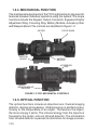
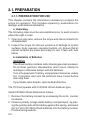
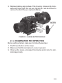
1
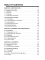
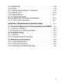
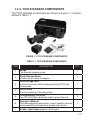
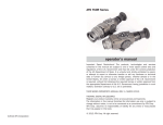
TICO Series THERMAL IMAGING CLIP-ON OPERATOR’S MANUAL (TICO Series) REVISION 5 – SEP, 2014 o p e r a t o r ’s m a n u a l Important Export Restrictions! Commodities, products, technologies and services contained in this manual are subject to one or more of the export control laws and regulations of the U.S. Government and they fall under the control jurisdiction of either the US Department of State or the US BIS-Department of Commerce. It is unlawful and strictly prohibited to export, or attempt to export or otherwise transfer or sell any hardware or technical data or furnish any service to any foreign person, whether abroad or in the United States, for which a license or written approval of the U.S. Government is required, without first obtaining the required license or written approval from the Department of the U.S. Government having jurisdiction. Diversion contrary to U.S. law is prohibited. Register your product warranty online at www.atncorp.com/warranty Manual (TICO Series) Revision 5 – September, 2014 The information in this manual furnished for information use only, is subject to change without notice, is not to be construed as a commitment by ATN Corp. ATN Corp. assumes no responsibility or liability for any errors or inaccuracies that may appear in this book. © 2014 ATN Corp. All right reserved. SAFETY SUMMARY STUDY CAREFULLY THIS MANUAL BEFORE TURNING ON AND OPERATING THIS PRODUCT. CAUTIONS The TICO Series Thermal Imaging Clip-On are precision electro-optical instruments and requires careful handling. To provide safe use of the systems the following instructions should be observed: •Do not dismantle the device. •Keep the device clean; protect it from moisture, sharp temperature drops and shocks. •Be careful not to touch the glass surfaces. If you put finger-prints on, or contaminate the glass surfaces, use only clean and soft materials to clean it. •Do not leave the device in on position during stops in operation. •Remove the batteries from the device for the period of storage. CAU TION : THIS PRODUCT CONTAINS NATURAL RUBBER LATEX WHICH MAY CAUSE ALLERGIC REACTIONS. a WARNING Do not permanently attach the scope to dynamic-mount applications that continuously transmit vibration (such as on vehicles or heavy machinery). WARNING Do not point the scope directly at any high-intensity objects that you must not view with your eyes (such as the sun or a welding arc). If you do, you will damage the scope. WARNING Operating TICO Series outside of its specified operating temperature range or voltage range can cause permanent damage and will void the warranty. WARNING Use the power button to turn the scope off before you remove power (remove batteries or disconnect external power supply). WARNING TICO Series operates over a wide operating temperature range (-20°C to +60°C). Not all lithium batteries are specified over this same temperature span. Check the manufacturer’s specifications of your selected battery to verify the valid temperature range. WARNING Do not use any battery other than a CR-123A lithium battery. DO NOT use any battery(ies) providing a (combined) voltage greater than 12.0 volts. WARNING Do not install batteries of different types (lithium with lithium-ion rechargeable). All batteries must be of the same type. WARNING Do not replace batteries in a possibly explosive environment, such as a gas station (or any place where you must turn off your vehicle engine). If you do, sparks can cause an explosion. b WARNING Remove the batteries before you store the riflescopes for extended periods (2 weeks or more). WARNING Do not carry batteries in pockets containing metal objects such as coins, keys, etc. Metal objects can cause the batteries to short circuit and become very hot. In the case of lithium batteries, a short circuit could cause them to explode. WARNING Observe battery manufacturer’s guidelines for safe handling and proper disposal of batteries. EQUIPMENT LIMITATIONS •The TICO Series detector spectral band (7 to 14 mkm) provides a better penetration through smoke, smog, dust, water vapor etc. •Infrared radiation does not travel through glass and therefore the scope does not sense objects if they are behind a glass window. c TABLE OF CONTENTS CHAPTER 1. INTRODUCTION. . . . . . . . . . . . . . . . . 1-1 1.1. General Information. . . . . . . . . . . . . . . . . . . . 1.1.1. Scope. . . . . . . . . . . . . . . . . . . . . . . . . . . 1.1.2. Reports . . . . . . . . . . . . . . . . . . . . . . . . . . 1.1.3. Storage . . . . . . . . . . . . . . . . . . . . . . . . . . 1.1.4. Warranty Information. . . . . . . . . . . . . . . . . . . . 1-2 1-2 1-2 1-2 1-2 1.2. Description and Data. . . . . . . . . . . . . . . . . . . . 1-5 1.2.1. Description. . . . . . . . . . . . . . . . . . . . . . . . . 1-5 1.2.2. TICO Standard Components . . . . . . . . . . . . . . . 1-7 1.2.3. Specifications. . . . . . . . . . . . . . . . . . . . . . . 1-8 1.2.4. Mechanical Function. . . . . . . . . . . . . . . . . . . 1-10 1.2.5. Optical Function. . . . . . . . . . . . . . . . . . . . . . 1-10 1.2.6. Electrical Function . . . . . . . . . . . . . . . . . . . . 1-10 CHAPTER 2. ASSEMBLY AND PREPARATION. . . . . . . . 2-1 2.1. Preparation. . . . . . . . . . . . . . . . . . . . . . . . . 2-2 2.1.1. Preparation for Use. . . . . . . . . . . . . . . . . . . . 2-2 2.1.2. Examination for Operation . . . . . . . . . . . . . . . . . 2-3 2.2. Assembly. . . . . . . . . . . . . . . . . . . . . . . . . . 2.2.1. Quick Release Mount. . . . . . . . . . . . . . . . . . . 2.2.2. Light Suppressor. . . . . . . . . . . . . . . . . . . . . . 2.2.3. Video Output . . . . . . . . . . . . . . . . . . . . . . . . 2-4 2-4 2-5 2-6 CHAPTER 3. OPERATION . . . . . . . . . . . . . . . . . . . 3-1 3.1. General Information. . . . . . . . . . . . . . . . . . . . 3-2 3.1.1. General . . . . . . . . . . . . . . . . . . . . . . . . . . 3-2 3.1.2. Controls and Indication . . . . . . . . . . . . . . . . . . 3-2 3.2. Operating procedure . . . . . . . . . . . . . . . . . . . . 3.2.1. Turning On . . . . . . . . . . . . . . . . . . . . . . . . . 3.2.2. Focusing . . . . . . . . . . . . . . . . . . . . . . . . . . 3.2.3. ISM – Interactive Symbology Menu. . . . . . . . . . . . 3.2.4. Polarity. . . . . . . . . . . . . . . . . . . . . . . . . . . i 3-3 3-3 3-4 3-5 3-7 3.2.5. Brightness. . . . . . . . . . . . . . . . . . . . . . . . . 3-8 3.2.6. Zoom. . . . . . . . . . . . . . . . . . . . . . . . . . . . 3-8 3.2.7. Manual Image Refresh / Calibration . . . . . . . . . . . . 3-9 3.2.8. Reticle Color . . . . . . . . . . . . . . . . . . . . . . . 3-10 3.2.9. Reticle Pattern . . . . . . . . . . . . . . . . . . . . . . 3-10 3.2.10. Optical Alignment: Reticle Adjustment / Windage and Elevation . . . . . . . . . . 3-10 3.2.11. Shut Down Operations. . . . . . . . . . . . . . . . . . 3-11 CHAPTER 4. MAINTENANCE INSTRUCTIONS. . . . . . . . 4-1 4.1. Preventive Maintenance Checks and Services (PMCS). . 4-2 4.1.1. Purpose of PMCS. . . . . . . . . . . . . . . . . . . . . 4-2 4.1.2. Frequency of Performing PMCS . . . . . . . . . . . . . . 4-2 4.2. Troubleshooting . . . . . . . . . . . . . . . . . . . . . . 4-4 4.2.1. General . . . . . . . . . . . . . . . . . . . . . . . . . . 4-4 4.2.2. Troubleshooting Procedures . . . . . . . . . . . . . . . . 4-4 4.3. Maintenance Procedures . . . . . . . . . . . . . . . . . 4.3.1. Scope Maintenance. . . . . . . . . . . . . . . . . . . . 4.3.2. Cleaning Procedures . . . . . . . . . . . . . . . . . . . 4.3.3. Preparing for Extended Storage . . . . . . . . . . . . . . 4-5 4-5 4-5 4-6 ii HOW TO USE THIS MANUAL •Usage You must familiarize yourself with the entire manual before operating the equipment. Read and follow all warning notices. •Manual Overview The table of contents includes the paragraph number, paragraph title, and page number. An index provides additional references to the subject contents. iii CHAPTER 1 INTRODUCTION 1-1 1.1. GENERAL INFORMATION 1.1.1. SCOPE This manual contains instructions for use in operating and maintaining the TICO Thermal Imaging Clip-On. Throughout this manual, the TICO Series will be referred to as the scope or TICO. 1.1.2. REPORTS Reports from the user on recommendations for improvements are encouraged. Send reports to the address below. American Technologies Network Corp. 1341 San Mateo Avenue South San Francisco, CA 94080 (800) 910-2862 (650) 989-5100 (650) 875-0129 fax [email protected] www.atncorp.com 1.1.3. STORAGE Storage of TICO should be done in the factory packing and after a thorough PMCS as outlined in Section 4.1 of this manual. This will ensure the scope remains in mission ready condition during storage. Batteries should be stored separately from the scope. The scope should not be placed on the floor, in any area exposed to high temperatures or direct sunlight. Presence of acid and alkaline vapor, as well as of other aggressive admixtures in the air is unacceptable. 1.1.4. WARRANTY INFORMATION NOTICE: All TICO models with manufacture date post January 1, 2014 are warranted by the following: 1-2 3 YEAR PRODUCT WARRANTY This product is guaranteed to be free from manufacturing defects in material and workmanship under normal use for a period of 3 (three) years from the date of purchase. In addition the uncooled thermal sensor array carries a 10 year warranty. In the event a defect that is covered by the foregoing warranty occurs during the applicable period stated above, ATN, at its option, will either repair or replace the product, and such action on the part of ATN shall be the full extent of ATN’s liability, and the Customer’s sole and exclusive remedy. This warranty does not cover a product (a) used in other than its normal and customary manner; (b) subjected to misuse; (c) subjected to alterations, modifications or repairs by the Customer of by any party other than ATN without prior written consent of ATN; (d) special order or “close-out” merchandise or merchandise sold “as-is” by either ATN or the ATN dealer; or (e) merchandise that has been discontinued by the manufacturer and either parts or replacement units are not available due to reasons beyond the control of ATN. ATN shall not be responsible for any defects or damage that in ATN’s opinion is a result from the mishandling, abuse, misuse, improper storage or improper operation, including use in conjunction with equipment which is electrically or mechanically incompatible with or of inferior quality to the product, as well as failure to maintain the environmental conditions specified by the manufacturer. This warranty is extended only to the original purchaser. Any breach of this warranty shall be waived unless the customer notifies ATN at the address noted below within the applicable warranty period. The customer understands and agrees that except for the foregoing warranty, no other warranties written or oral, statutory, expressed or implied, including any implied warranty of merchantability or fitness for a particular purpose, shall apply to the product. All such implied warranties are hereby and expressly disclaimed. LIMITATION OF LIABILITY ATN will not be liable for any claims, actions, suits, proceedings, costs, expenses, damages or liabilities arising out of the use of this product. Operation and use of the product are the sole responsibility of the Customer. ATN’s sole undertaking is limited to providing the products and services outlined herein in accordance with the terms and conditions of this Agreement. The provision of products sold and services performed by ATN to the Customer shall not be interpreted, construed, or regarded, either expressly or implied, as being for the benefit of or creating any obligation toward any third party of legal entity outside ATN and the Customer; ATN’s obligations under this Agreement extend solely to the Customer. ATN’s liability hereunder for damages, regardless of the form or action, shall not exceed the fees or other charges paid to ATN by the customer or customer’s dealer. ATN shall not, in any event, be liable for special, indirect, incidental, 1-3 or consequential damages, including, but not limited to, lost income, lost revenue, or lost profit, whether such damages were foreseeable or not at the time of purchase, and whether or not such damages arise out of a breach of warranty, a breach of agreement, negligence, strict liability or any other theory of liability. PRODUCT WARRANTY REGISTRATION In order to validate the warranty on your product, ATN must receive a completed Product Warranty Registration Card for each unit or complete warranty registration on our website at www.atncorp.com. Please complete the included form and immediately mail it to our Service Center: ATN Corporation, 1341 San Mateo Avenue, South San Francisco, CA 94080. OBTAINING WARRANTY SERVICE To obtain warranty service on your unit, End-user must notify ATN service department by calling 800-910-2862 or 650-989-5100 or via e-mail service@ atncorp.com to receive a Return Merchandise Authorization number (RMA). When returning please take or send the product, postage paid, with a copy of your sales receipt to our service center, ATN Corporation at the address noted above. All merchandise must be fully insured with the correct postage; ATN will not be responsible for improper postage or, missing or damaged merchandise during shipment. When sending product back, please clearly mark the RMA# on the outside of the shipping box. Please include a letter that indicates your RMA#, Name, Return Address, reason for service return, Contact information such as valid telephone numbers and/or e-mail address and proof of purchases that will help us to establish the valid start date of the warranty. Product merchandise returns that do not have an RMA listed may be refused or a significant delay in processing may occur. Estimated Warranty service time is 10-20 business days. End-user/customer is responsible for postage to ATN for warranty service. ATN will cover return postage/shipping to continental USA end-users/ customers after warranty repair only if product is covered by aforementioned warranty. ATN will return product after warranty service by domestic ground service and/or domestic mail. Any other requested, required or international shipping method the postage/shipping fee will be the responsibility of the enduser/customer. 1-4 1.2. DESCRIPTION AND DATA 1.2.1. DESCRIPTION a. Purpose Representing the latest advancement in thermal imaging technology, the ATN TICO-Series thermal clip-on gives your daytime scope thermal imaging capability in a matter of seconds. The ATN TICO-Series mounts in front of a daytime scope to enable thermal vision in day or nighttime operation. No shift of impact, no need to rezero nor change of eye relief occurs. The ATN TICO-Series uses advanced thermal technology for outstanding resolution and performance. Precision optical alignment is essential for any front sight system to work properly. Therefor every ATN TICO-Series is individually tested and aligned to the highest tolerances to provide perfect alignment. b. Features TICO has the following important features: •Easily changes daytime scope to thermal imaging •Mounts in front of daytime scope, no re-zeroing required •Video output •Resistance to all severe operating conditions •Lightweight and rugged •Comes with quick release mount •High resolution digital thermal imaging •Compact, lightweight and durable housing •High-end OLED display •Rapid start-up in 3 seconds •Up to 4 hours operation •Three-Year Warranty •Aircraft aluminum constructed body with class 3 hard ano dized coating •Digital Tactical Menu with quick view icons 1-5 •Polarity: white hot / black hot / color •Thermal images viewable in up to 12-tone color pallet •Ten-step brightness control •Batteries: (2) 3V lithium (CR123A). 1-6 1.2.2. TICO STANDARD COMPONENTS The TICO standard components are shown in Figure 1.1. and presented in Table 1.1. FIGURE 1.1. TICO STANDARD COMPONENTS TABLE 1.1. TICO STANDARD COMPONENTS ITEM DESCRIPTION QTY 1 Scope The thermal imaging scope. 1 2 Quick Release Mount Used to mount scope to weapon. 1 3 Hard Storage Case A protective case used for shipping/storing TICO and accessories. 1 4 Lens Tissue Uses for cleaning of lenses surface. 1 5 Lithium Battery CR1223A Two CR123A lithium batteries used to power the unit. 2 6 Operator’s Manual Provides equipment description, use of operator controls and preventative maintenance checks and service. 1 7 Rubber Light Suppressor for the Scopes 1 1-7 1.2.3. SPECIFICATIONS The following tables provide information pertaining to the operational, electrical, mechanical, optical and environmental characteristics for the sights. TABLE 1.2. SPECIFICATIONS ITEM Sensor (microbolometer) Frame rate Material Image Size (output resolution) Video output Display Thermal Sensitivity Spectral Response Field of View (H x V) Optical Magnification Pixel Size Distance of the human detection (w/o zoom) Distance of the human recognition (w/o zoom) Distance of the human Identification (w/o zoom) Distance of the vehicle detection (w/o zoom) Distance of the vehicle recognition (w/o zoom) Distance of the vehicle Identification (w/o zoom) Contrast adjustment Polarity control Start up time 1-8 TICO-336 TICO-640 336x256 30 or 60 Hz 640x512 30 Hz VoX 800x600 px Digital NTSC / PAL Color OLED matrix, SVGA< 800x600 <50 mK 7-14 μm 9° x 7° 1x 17 μm 1100 m 400 m 225 m 2425 m 875 m 525 m Manual White hot / Black hot / Multiple Color Modes <3 s ITEM TICO-336 TICO-640 Waterproof Battery type Battery Life Waterproof / Dustproof 2 x CR123A 4+ h Mounting bracket MIL-STD 1913 Picatinny (Quick Detach) Video output Low Battery Indicator Iconology Housing Objective lens Dimensions (with mount) Weight Warranty Yes Yes Quick access via Icon driven feature controls Aircraft Aluminum 6061 T6 w/hard anodized coating 50mm, full MIL SPEC, with DLC coating 189 x 69 x 65mm/7.45 x 2.7 x 2,56” 0.64 kg / 1.45 lbs 3 year * ATN reserves the right to change the above specifications at any time without notice. 1-9 1.2.4. MECHANICAL FUNCTION The mechanical adjustments of the TICO sights allow for physical differences between individual operators using the system. The scope functions include the Keypad, Output Connector, Eyepiece Diopter Adjustment Ring, Focusing Ring, Battery Module, Accessory Rail, and Weapon Mount. The controls are identified in Figure 1.2. KEYPAD WEAPON MOUNT FOCUS KNOB BATTERY MODULE ACCESSORY RAIL WEAPON MOUNT RELEASE FIGURE 1.2. TICO MECHANICAL CONTROLS 1.2.5. OPTICAL FUNCTION The optical functions include an objective lens, thermal imaging detector, display and eyepiece. Infrared energy is emitted proportionally to the temperature of an object. The warmer the object, the more energy it emits. The infrared energy from the objects is focused by the optics, onto an infrared detector. The information from infrared detector is passed to electronics for image process1-10 ing. The signal processing circuitry translates the infrared detector data into an image that can be viewed on the built-in OLED display. The image is observed through an eyepiece by operator. 1.2.6. ELECTRICAL FUNCTION The electronic circuit is powered by replaceable two 3V lithium batteries (CR123A). Power from the batteries is supplied to the components through the Power button. 1-11 1-12 CHAPTER 2 ASSEMBLY AND PREPARATION 2-1 2.1. PREPARATION 2.1.1. PREPARATION FOR USE This chapter contains the information necessary to prepare the scope for operation. This includes unpacking, examination for damage, and batteries installation. a. Unpacking The following steps must be accomplished prior to each mission where the sight is used. 1. Open carrying case, remove the scope and check contents for completeness. 2. Inspect the scope for obvious evidence of damage to optical surfaces, body, eyecups, operation buttons, etc. Ensure that all optical surfaces are clean and ready for use. Clean with lens tissue. b. Installation of Batteries WARNING The lithium battery contains sulfur dioxide gas under pressure. Do not heat, puncture, disassemble, short circuit, attempt to recharge or otherwise tamper with the batteries. Turn off equipment if battery compartment becomes unduly hot. If possible, wait until the batteries have cooled before removing them. If you inhale sulfur dioxide, seek medical attention. The TICO will operate with 2 CR123A Lithium batteries type. Install CR123A Lithium batteries as follows. 1. Remove the battery module by unscrewing the knob counter clockwise. 2. Observe polarity (image inside battery compartment), by placing the positive side of the battery against the spring, and insert the 3.0 Volt CR 123A Lithium batteries into the battery module. Positive facing inwards. 2-2 3. Replace battery cap module of the housing. Screw knob clockwise until finger tight. Do not over tighten as it will be difficult to remove the next time you replace batteries. BATTERY MODULE FIGURE 2.1. LOADING BATTERY MODULE 2.1.2. EXAMINATION FOR OPERATION Before getting started, make sure to follow these steps: 1. Push Power button on the scope. 2. Make sure that the luminance in ocular is present. 3. Observe the scene, and adjust the diopter and/or lens for optimal image clarity. 2-3 2.2. ASSEMBLY 2.2.1. QUICK RELEASE MOUNT Quick Release Mount (QRM) is used for fast installation/removing the TICO on MIL-STD-1913/Picatinny rail. NOTE Optical axes of the TICO and the riflescope should be matched. Difference of the axes position more than 3 mm is not re-commended. Measure the height of the riflescope axis above the rail. If the difference in the axis heights of the TICO and riflescope is more than 3 mm it is necessary to replace riflescope mounting rings or base by proper ones. A MOUNT LEVER B FIGURE 2.2. TICO INSTALLED ON MIL-STD-1913 RAIL FORWARD OF TRIJICON ACOG 1. Slide the locking arm of mount lever forward (Figure 2.2, arrow A). Turn the mount lever perpendicular to open the mount (Figure 2.2, arrow B). 2. Install the sight forward the riflescope on the arm rail as close to the riflescope as possible. The light suppressor should cover the riflescope objective lens. 2-4 3. Turn the lever backwards (parallel) to close the mount. NOTE If using weaver rails, please consult your gunsmith for modification to rail. 2.2.2. LIGHT SUPPRESSOR Your TICO comes with a rubber light suppressor attachment. To use the light suppressor: 1. Unscrew the external eyepiece ring. FIGURE 2.3. 2. Next, place the small diameter of the rubber light suppressor over the threaded portion of the eyepiece. FIGURE 2.4. 3. Now the TICO can be mounted ahead of a day scope with the light suppressor. FIGURE 2.5. TICO WITH LEUPOLD DAY SCOPE ON LONG RAIL 2-5 2.2.3. VIDEO OUTPUT This version of the TICO is equipped with the added feature of being able to connect directly to a remote video monitor or recorder via an integrated video output port. 1.Connect the video cable to the sights video output port. 2.Connect the video cable to the appropriate recording device. Operation: 1.Turn on the system by pressing the POWER button. 2. Let screen image settle before transferring video to the monitor. VIDEO OUTPUT PORT 3.Press the “ Up” and “ Down” arrow but tons simultaneously, as show FIGURE 2.6. TICO WITH VIDEO CABLE in the photo above. The Video image will now be able to be viewed through the TICO eyepiece and the monitor at the same time. The user, while looking through the TICO eyepiece, will be able to tell if video is being displayed on the monitor, because the VID icon will be visible in the bottom left corner of the eyepiece. 4. To turn off the Remote Video Output, repeat step 3. FIGURE 2.7. OPERATION SWITCHBOARD NOTE The image seen in the TICO sight will be smaller than its actual resolution, due to the video processing differing from that of a monitor. 2-6 CHAPTER 3 OPERATION 3-1 3.1. GENERAL INFORMATION 3.1.1.GENERAL This section contains instructions for operation of TICO. The function of controls and indicators is explained. CAUTION The TICO scope is a precision electron-optical instrument and must be handled carefully at all times. 3.1.2.CONTROLS AND INDICATION The TICO is designed to adjust for different users and corrects for most differences. The controls for the scope are shown or described in Figure 3.1. and Tables 3.1. FOCUS KNOB POWER BUTTON ENTER BUTTON LEFT ARROW BUTTON DOWN ARROW BUTTON UP ARROW BUTTON RIGHT ARROW BUTTON FIGURE 3.1. CONTROLS 3-2 TABLE 3.1. CONTROLS AND INDICATION ITEMS CONTROLS AND INDICATORS FUNCTIONS 1 POWER Button Controls TICO power. To turn the unit on and off press the button 2 ENTER Button Used to select or enter selection 3 Up Arrow Calibration, Reticle Color 4 Down Arrow Brightness, Saved Ballistic Profile 5 Left Arrow Color, Reticle On/Off 6 Right Arrow Calibration, Reticle adjustment 3.2. OPERATING PROCEDURE 3.2.1. TURNING ON Open the objective lens cover. NOTE The objective lens cover protects the scope from inadvertent exposure to extremely high levels of radiant flux. Never leave the scope with the objective lens cover off. To turn the unit on press the button labeled POWER. After a warm-up time of approximately 3 seconds, video of the thermal scene appears. 3-3 NOTE During the warm-up time, a logo comes into view on the monocular display. Next the thermal image replaces the logo. FIGURE 3.2. SWITCHBOARD OF TICO 3.2.2. FOCUSING 1. To focus the scope you need to focus your dayscope first. 2. Once the TICO is mounted in front of your dayscope turn unit on. 3. Calibrate the thermal device (see page 3-9). 4. The front lens should be readjusted for viewing objects at different distances. Rotate the focusing knob clockwise for far focus, counterclockwise for near focus. 5. If the riflescope has focusing rings (parallax adjustment knob) adjust focus for parallax free image. 6. If the scope has reticle illumination, switch it on and adjust reticle brightness. FOCUS KNOB FIGURE 3.3. FOCUS ADJUSTMENT 3-4 NOTE The front lens should be readjusted for viewing objects at different distances. Rotate the focusing ring clockwise for far focus, counterclockwise for near focus. 3.2.3. ISM – INTERACTIVE SYMBOLOGY MENU The TICO features the all new ISM interactive symbology menu that enables you to easily navigate through the features and modes without having to go into a complex menu structure. Every mode and option can be found on one of the following ISM screens: MAGNIFICATION COLOR CALIBRATION BRIGHTNESS FIGURE 3.4. ISM MAIN MENU 3-5 RETICLE COLOR RETICLE ADJUSTMENT RETICLE ON/ OFF SAVED BALLISTIC PROFILE FIGURE 3.5. ISM RETICLE MENU FIGURE 3.6. ISM NO MENU 3-6 BATTERY LEVEL INDICATOR 3.2.4. POLARITY The function of polarity switching is accessible only in Black and White models. WHITE HOT BLACK HOT FIGURE 3.7. DISPLAY POLARITY MODES Polarity: Polarity is the most common used thermal color modes. The function of polarity switching is accessible only in Black and White models. Polarity button switches the direct display mode into the reverse one, i.e. from hot-white/cold-black into hot-black/coldwhite mode. If the polarity is white-hot, the image will be with hotter objects displayed as white, and the rest of the image displayed as black, and vice versa: with hotter objects displayed as black, if the polarity is black-hot. To select polarity go to ISM Main menu and push left arrow button (color mode) quickly to cycle between white hot and black hot polarities. The TICO has 10 additional color pallets to choose from in addition to the white hot and black hot polarity. Fusion, Rainbow, Globow, Ironbow1, Ironbow2, Sepia, Color1, Color2, Ice Fire, Rain. To select a different colors mode go to ISM Main menu left arrow button (color mode). And hold down for 1-2 seconds to cycle through the 10 additional pallets. 3-7 IRONBOW COLOR 1 GLOBOW FIGURE 3.8. COLOR MODES 3.2.5. BRIGHTNESS Brightness allows you to dim or increase the brightness of the display. To cycle through the BRIGHTNESS steps go to ISM Main menu and push the down arrow button for brightness adjustment. Each short push of the buttons will cycle through the BRIGHTNESS modes, correspondingly, in stepwise way. NOTE Levels 1 to 6 range from full dim to full bright. 3.2.6. ZOOM 320x240 models have 2 steps of digital zoom (factor of 2x and 4x) 640x480 models have 3 steps of digital zoom (factor of 2x, 4x and 8x). To cycle through the digital zoom steps go to ISM Main menu and push Up arrow button. When ZOOM button is pushed first time, the scope will digitally zoom a scene by 2 times the scopes optical magnification. When the zoom button is pushed the second time the scope will digitally zoom a scene by 4 times the scopes optical magnification for TICO models with the 320x240 core. To reset the magnification to the default optical magnification press ZOOM button third time. For TICO models with the 640x480 core when the zoom button is pushed the third time the scope will digitally zoom a scene by 8 times the scopes optical magnification. To reset the magnification to the default optical magnification press ZOOM button fourth time. 3-8 NOTE Resolution decreases with each step of digital magnification. The reticle has a built in compensation to shift and stay on the target during digital zoom operations as depicted in Figure 3.9. NO ZOOM RETICLE ON TARGET 2X ZOOM RETICLE SHIFTS 2X 4X ZOOM RETICLE SHIFTS 4X FIGURE 3.9. ZOOM 3.2.7. MANUAL IMAGE REFRESH / CALIBRATION Degradation of the image (image blurring) is caused by charge accumulation on the detector array. To use the calibration icon go to ISM Reticle menu and push down arrow button to maintain an optimum thermal image. During this refresh, the video will freeze for approximately 0.5 second. IMPORTANT: To Perform calibration of unit. Cover front lens with cap or hand and push Calibration button to calibrate image. Failure to do this step may result in degradation of the image. Degradation may consist of unusual blurriness or ghost like spots in the image. During use if you see any degradation of image please recalibrate the scope. Perform a calibration upon every substantial environmental temperature change. NOTE While performing very frequent Refreshes can provide the best possible image quality but also can substantially decrease the battery life. 3-9 DURING CAL CORRECT VIEW CORRECT CAL IF LENS IS COVERED INCORRECT CAL IF LENS IS NOT COVERED FIGURE 3.10. CALIBRATION (NUC) 3.2.8. RETICLE COLOR Your scope has Four reticle colors to choose from: red, green, white, black, the latest firmware also includes many bonus colors. To select reticle colors go to ISM Reticle menu and push Up arrow button to cycle through the reticle colors. RED WHITE BLACK GREEN FIGURE 3.11. RETICLE ADJUSTMENT 3.2.9. RETICLE PATTERN Your scope has a reticle that can be turned on for image alignment in scope set up. After alignment turn off reticle. To select reticle on/ off go to ISM Reticle menu and push Left arrow button to turn reticle on/off. 3.2.10. OPTICAL ALIGNMENT: RETICLE ADJUSTMENT/WINDAGE AND ELEVATION To optically align the TICO to your dayscope go to ISM Reticle menu and push Right arrow button reticle adjustment. 3-10 This will bring you to ISM Reticle Adjustment menu which will allow you to do your vertical and horizontal adjustments. To adjust vertical and horizontal adjustments for the scope use corresponding arrows: •Up Up arrow for up adjustment •Down arrow for down adjustment •Left arrow for left adjustment •Right arrow for right adjustment FACTORY DEFAULT ELEVATION ADJUSTMENT WINDAGE ADJUSTMENT FIGURE 3.12. WINDAGE AND ELEVATION ADJUSTMENTS 3.2.11. SHUT DOWN OPERATIONS To finish the work, perform the following: 7. Use the POWER button to turn the scope off. 8. Hold down the POWER button (3 seconds) until the ? icon goes away then release the POWER button. This is a safety so the system is not accidentally turned off. 9. Return the scope to the case. STEP 1 PRESS AND HOLD POWER BUTTON AND SEE “?” STEP 2 RELEASE POWER BUTTON WHEN “OK” APPEARS ON SCREEN FIGURE 3.13. POWER DOWN 3-11 3.2.12. SIGHTING-IN THE CLIP-ON SCOPE 1. Insure your optical day scope is sighted in to your weapon. 2. If possible, lock down the weapon in a shooting vice, this will insure the highest level of accuracy. Now place the day scope reticle on a thermal target at the same distance that the day scope is sighted in to. 3. Attach the TICO to the weapon in front of the day scope. 4. At x1 zoom, press the “ENTER” button to get to the Reticle menu (Figure 3.2.) and press the Left Arrow button to change to Fine Cross with Dot reticle (Figure 3.14.) FIGURE 3.14. and then enter the reticule adjust level (Figure 3.15.). TICO ALIGNMENT RETICLE OPTICAL DAY SCOPE RETICLE FIGURE 3.15. 3-12 5. Adjust the TICO reticule until it is exactly on top of the day scope reticle(still at x1 zoom) (Figure 3.16.). FIGURE 3.16. 6. Exit the reticule adjust mode, and save the day scope reticle position to any ballistic profile location (Figure 3.17.). X= 0 Y= 0 1 2 4 3 FIGURE 3.17. 3-13 7. Return to the Reticle menu (Figure 3.18.) and scroll through unit the fine line and dot reticle is turned off. Now enter the reticule adjust level. RETICLE COLOR RETICLE TYPE RETICLE POSITION SAVED RETICLE LOCATION FIGURE 3.18. 8. Adjust the TICO image position using the up/down/left/right buttons on the TICO keypad, until the thermal target is centered under the day sight reticle. 9. Exit the reticule adjust menu without saving the offsets to a profile, change to max zoom, and re-enter the reticule adjust level. Fine tune the TICO image position up/down/left/right, until the thermal target is centered under the day sight cross hair at maximum zoom. 10.Now, save these offsets to the same ballistic profile. NOTE The amount of day sight windage and elevation movement varies with the zoom level. 3-14 CHAPTER 4 MAINTENANCE INSTRUCTIONS 4-1 4.1. PREVENTIVE MAINTENANCE CHECKS AND SERVICES (PMCS) 4.1.1. PURPOSE OF PMCS PMCS is performed daily when in use to be sure that the sight is ready at all times. Procedures listed in Table 4.1. are a systematic inspection of TICO that will enable you to discover defects that might cause the sight to fail on a mission. 4.1.2.FREQUENCY OF PERFORMING PMCS The frequency of performing PMCS is as follows: a. Daily when the sight is in use. b. When it is removed from the case for any reason. TABLE 4.1. PREVENTIVE MAINTENANCE CHECKS AND SERVICES SEQ. NO. ITEM TO CHECK CHECKING PROCEDURE NOT FULLY MISSION CAPABLE IF: 1 Completeness Inventory items by means of comparing with the data specified in this manual. Items missing. 2 Sight Body Inspect for missing screws or connector cap. Screws or connector cap missing. 3 Front Lens Cap Inspect for cuts, tears and dirt. Clean as required. Cap torn or cut. 4 Battery Compartment Check for corrosion, springs tension. Springs corroded or damaged. 5 Lenses Inspect for cleanliness, scratches, chips or cracks. Clean as required. Chipped, cracked or if scratches hinder vision through the sight. 6 Objective Lens Check to ensure the objective lens is not loose. Objective lens loose. 4-2 SEQ. NO. ITEM TO CHECK CHECKING PROCEDURE 7 Focus Ring Check to ensure: — the focus ring cannot be moved along the sight body; — there is free rotation of the focus ring (more than 3/4 turn). 8 Rubber Eye-cup Inspect for cuts or tears NOT FULLY MISSION CAPABLE IF: Focus ring able to move along sight body. Focus ring cannot be rotate Rubber Eye-cup torn or cut AFTER CHECKING PROCEDURES 9 Replace protective covers on the lenses. Remove the batteries. Return the scope and all accessories to the storage case. 4-3 4.2. TROUBLESHOOTING 4.2.1.GENERAL This section contains information for locating and removal most of the TICO operating troubles which may occur. Each malfunction for an individual component or assembly is followed by a list of tests or inspections that will help determine probable causes and corrective action to take. Perform the tests/inspections and corrective actions in the order listed. This manual cannot list all possible malfunctions that may occur, or all tests or inspections and corrective actions. If a malfunction is not listed (except when malfunction and cause are obvious), or is not corrected by listed corrective actions, contact to the service center. 4.2.2.TROUBLESHOOTING PROCEDURES Troubleshooting procedures are listed in Table 4.2. TABLE 4.2. TROUBLESHOOTING PROCEDURES PROBLEM Image is absent Cannot achieve the sharp image of the object. The brightness of the image on the screen is low. 4-4 PROBABLE CAUSE CORRECTIVE ACTION Batteries are missing or improperly installed. Insert batteries or install correctly. Batteries are dead. Replace batteries. Batteries contact surfaces or contact springs dirty or corroded. Clean the contact surfaces with a pencil eraser and/or alcohol and cotton swabs. Objective and output lenses dirty. Clean thoroughly the lenses surfaces. Damaged optical components. Send the sight to the service center. The batteries have a low voltage. Replace the batteries. Factory alignment broken. Send the scope to the service center. 4.3. MAINTENANCE PROCEDURES 4.3.1. SCOPE MAINTENANCE The TICO maintenance consists of external inspection of its components for serviceability, cleaning and installation of the standard and optional accessories. Maintenance instructions covered elsewhere in this manual (PMCS, troubleshooting, etc.) are not repeated in this section. CAUTION The TICO is a precision electron-optical instrument and must be handled carefully at all times to prevent damage. 4.3.2. CLEANING PROCEDURES a. Cleaning the scope 1. Gently brush off any dirt from the sight body using only a clean soft cloth. 2. Moisten the cloth with fresh water and gently wipe the external surfaces (except lenses). 3. Dry any wet surfaces (except lenses) with another dry and clean soft cloth. 4. Using lens brush, carefully remove all loose dirt from the lenses. 5. Slightly dampen a cotton swab with ethanol and lightly and slowly wipe the lenses. Clean the glass surfaces by circular movements from the center to the edge, not touching the lens holder and changing cotton swab after each circular stroke. Repeat this step until the glass surfaces are clean. b. Cleaning of accessories Clean accessories with a soft brush (cloth) and soap and water as required. CAUTION Dry thoroughly each item before replacing into the storage case. 4-5 4.3.3. PREPARING FOR EXTENDED STORAGE To prepare the TICO for extended storage, perform the following: 1. Check the scope for serviceability as outlined in item 4.1 of this manual. 2. Remove the batteries. 3. Clean the scope and accessories. 4. Replace all items in the case. 4-6 4-7 For customer service and technical support, please contact American Technologies Network Corp. 1341 San Mateo Avenue, South San Francisco, CA 94080 phone: 800-910-2862, 650-989-5100; fax: 650-875-0129 www.atncorp.com ©2014 ATN Corporation