1
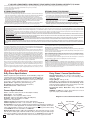
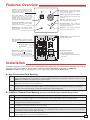
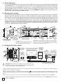
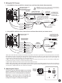
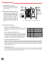
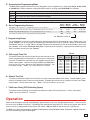
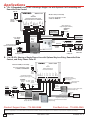
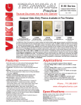
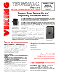
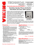
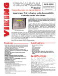
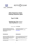
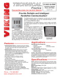
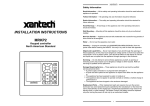
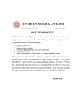
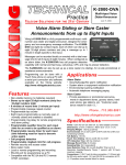
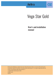
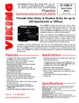
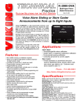
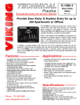
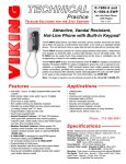
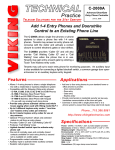
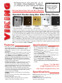
TECHNICAL
Practice
Practice
TELECOM SOLUTIONS
FOR THE
E-65 Series
Double Gang Entry
Phones with Color
Video Camera
2 1 S T C E N T U RY
July 1, 2014
Standard Double Gang Box Video Entry Phones
E-65-SS
E-65-BN
“Brushed Stainless Steel” (similar to
“Oil Rubbed Bronze”
brushed nickel) Optional VE-5x5 surface
(satin dark brown powder
mount box shown (not included)
paint with fine copper metallic)
E-65-PB
E-65-WH
E-65-BK
“Polished Brass”
(with clear gloss powder
paint to prevent tarnishing)
“Satin White”
(satin white powder paint)
“Satin Black”
(fine texture satin black
powder paint)
The E-65 Series Video Entry phones are compact, weather and vandal resistant speaker phones designed to provide two-way handsfree audio communication and color composite video of who is at your door or gate. The E-65's compact size allows it to be mounted
in a standard single gang electrical box. The E-65 is available in five different attractive finishes to match your door hardware, light fixtures, etc. Replacement E-65 faceplates (PNL65) can be purchased separately and are available in all five standard finishes. The E65 entry phones can share a single phone line with house or small business telephones when used with a Viking model C-200, C-250,
C-500 or C-2000B Entry Phone controller. The E-65 entry phones can also be connected to an unused analog station port (programmed for ring down) on a phone system or connected directly to a telephone line when used with a Viking K-1900-5 or K-1900-30
dialer. The E-65 features a built-in high resolution color video camera, microphone and speaker volume controls, selectable auto
answer for monitoring and intelligent call progress detection for automatic hang-up when the call is completed. For outdoor installations where the unit is exposed to precipitation or condensation, the E-65 Series is available with Enhanced Weather Protection
(EWP). For more information on EWP, see DOD# 859.
Features
• Built-in high resolution color video camera with wide viewing angle,
tilt/swivel adjustments, and wide operating temperature of -30° F to 150° F
• Audio and video transmission on one CAT5E cable (see page 5)
• Compact size: Front panel is the size of a typical double gang midsize wall plate
• Mounting: Flush mounts in a double gang electrical box (2.25” deep
x 3.65” wide x 2.84” tall minimum) or surface mounts in a Viking
model VE-5x5 (not included, see DOD# 424) for mounting to a wall,
post or VE-GNP Gooseneck Pedestal (EWP recommended)
• Available in 5 standard faceplate finishes: Brushed Stainless Steel,
Oil Rubbed Bronze, Polished Brass, Satin Black and Satin White
• PNL-65 faceplates: Replacement faceplates with matching screws
available in all five standard finishes
• Vandal Resistant Features: 16 gauge polished brass or 18 gauge
304 stainless steel faceplate, 316 stainless steel push button,
stainless steel speaker screen, scratch resistant powder coating,
impact and scratch resistant camera lens, hex drive mounting screws
• Weather Resistant Features: Mylar speaker, faceplate gasket, mic
and speaker gasket, internally sealed (IP67) push button switch,
sealed camera lens, potted camera circuit board, stainless steel phone
and camera mounting hardware and UV stable weather resistant
powder coating (excludes E-65-SS)
• E-65-EWP is designed to meet IP66 Ingress Protection Rating (see
DOD# 859)
• Blue LED helps locate the push button, indicate ringing and off-hook
• Telephone line powered
• Microphone and speaker volume controls
• Programmable Intelligent call progress detection for automatic
hang-up on CPC, silence, busy signal, or time out
Applications
• Door or gate communication, business delivery entrances
• Use with a Viking C-200 or C-250 to control one E-65 on a single
phone line
• Use with a Viking C-500 to control 1 or 2 (expandable to 8) E-65’s
and door/gate control on a single phone line
• Use with a Viking C-2000B to control 1 to 4 E-65’s and door/gate
control on a single phone line
• Provide unique front and back door chimes and paging when used
with a Viking SLP-1 or SLP-4 and C-2000B
• Residential, commercial and industrial door security
• Use with a Viking K-1900-5 or K-1900-30 for automatic speed
dialing on telephone lines or analog PABX/KSU station ports
• Use on any analog PABX station port with programmable ringdown
capability
Phone...715.386.8861
[email protected]
h t t p : / / w w w. v i k i n g e l e c t r o n i c s . c o m
Specifications
Dimensions: Faceplate: 123.8mm x 125.4mm x 4.3mm (4.875” x 4.938” x 0.17”), Phone:
72mm x 46mm x 42mm (2.84” x 1.8” x 1.65”)
Shipping Weight: 0.55 kg (1.2 lbs)
Operating Temperature: -34° C to 65° C (-30° F to 150° F)
Connections: (2) gel-filled butt connectors (3M Scotchlok UR2)
(See page 2 for complete specifications)
IF YOU HAVE A PROBLEM WITH A VIKING PRODUCT, PLEASE CONTACT: VIKING TECHNICAL SUPPORT AT (715) 386-8666
Our Technical Support Department is available for assistance Monday 8am - 4pm and Tuesday through Friday 8am - 5pm central time. So that we can give you better service, before you call please:
1. Know the model number, the serial number and what software version you have (see serial label).
2. Have your Technical Practice in front of you.
3. It is best if you are on site.
RETURNING PRODUCT FOR REPAIR
RETURNING PRODUCT FOR EXCHANGE
The following procedure is for equipment that needs repair:
1. Customer must contact Viking's Technical Support Department at 715-386-8666 to obtain a Return Authorization (RA)
number. The customer MUST have a complete description of the problem, with all pertinent information regarding the
defect, such as options set, conditions, symptoms, methods to duplicate problem, frequency of failure, etc.
2. Packing: Return equipment in original box or in proper packing so that damage will not occur while in transit. Static
sensitive equipment such as a circuit board should be in an anti-static bag, sandwiched between foam and individually boxed. All equipment should be wrapped to avoid packing material lodging in or sticking to the equipment. Include
ALL parts of the equipment. C.O.D. or freight collect shipments cannot be accepted. Ship cartons prepaid to:
Viking Electronics, 1531 Industrial Street, Hudson, WI 54016
3. Return shipping address: Be sure to include your return shipping address inside the box. We cannot ship to a PO Box.
4. RA number on carton: In large printing, write the R.A. number on the outside of each carton being returned.
The following procedure is for equipment that has failed out-of-box (within 10 days of purchase):
1. Customer must contact Viking’s Technical Support at 715-386-8666 to determine possible causes for the problem. The
customer MUST be able to step through recommended tests for diagnosis.
2. If the Technical Support Product Specialist determines that the equipment is defective based on the customer's input
and troubleshooting, a Return Authorization (R.A.) number will be issued. This number is valid for fourteen (14)
calendar days from the date of issue.
3. After obtaining the R.A. number, return the approved equipment to your distributor, referencing the R.A. number. Your
distributor will then replace the product over the counter at no charge. The distributor will then return the product to
Viking using the same R.A. number.
4. The distributor will NOT exchange this product without first obtaining the R.A. number from you. If you haven't
followed the steps listed in 1, 2 and 3, be aware that you will have to pay a restocking charge.
TWO YEAR LIMITED WARRANTY
Viking warrants its products to be free from defects in the workmanship or materials, under normal use and service, for a period of two years from the date of purchase from any authorized Viking distributor. If at any time during the warranty
period, the product is deemed defective or malfunctions, return the product to Viking Electronics, Inc., 1531 Industrial Street, Hudson, WI., 54016. Customer must contact Viking's Technical Support Department at 715-386-8666 to obtain a Return
Authorization (R.A.) number.
This warranty does not cover any damage to the product due to lightning, over voltage, under voltage, accident, misuse, abuse, negligence or any damage caused by use of the product by the purchaser or others. This warranty does not cover
non-EWP products that have been exposed to wet or corrosive environments. This warranty does not cover stainless steel surfaces that have not been properly maintained.
NO OTHER WARRANTIES. VIKING MAKES NO WARRANTIES RELATING TO ITS PRODUCTS OTHER THAN AS DESCRIBED ABOVE AND DISCLAIMS ANY EXPRESS OR IMPLIED WARRANTIES OR MERCHANTABILITY OR FITNESS
FOR ANY PARTICULAR PURPOSE.
EXCLUSION OF CONSEQUENTIAL DAMAGES. VIKING SHALL NOT, UNDER ANY CIRCUMSTANCES, BE LIABLE TO PURCHASER, OR ANY OTHER PARTY, FOR CONSEQUENTIAL, INCIDENTAL, SPECIAL OR EXEMPLARY DAMAGES
ARISING OUT OF OR RELATED TO THE SALE OR USE OF THE PRODUCT SOLD HEREUNDER.
EXCLUSIVE REMEDY AND LIMITATION OF LIABILITY. WHETHER IN AN ACTION BASED ON CONTRACT, TORT (INCLUDING NEGLIGENCE OR STRICT LIABILITY) OR ANY OTHER LEGAL THEORY, ANY LIABILITY OF VIKING SHALL
BE LIMITED TO REPAIR OR REPLACEMENT OF THE PRODUCT, OR AT VIKING'S OPTION, REFUND OF THE PURCHASE PRICE AS THE EXCLUSIVE REMEDY AND ANY LIABILITY OF VIKING SHALL BE SO LIMITED.
IT IS EXPRESSLY UNDERSTOOD AND AGREED THAT EACH AND EVERY PROVISION OF THIS AGREEMENT WHICH PROVIDES FOR DISCLAIMER OF WARRANTIES, EXCLUSION OF CONSEQUENTIAL DAMAGES, AND EXCLUSIVE REMEDY AND LIMITATION OF LIABILITY, ARE SEVERABLE FROM ANY OTHER PROVISION AND EACH PROVISION IS A SEPARABLE AND INDEPENDENT ELEMENT OF RISK ALLOCATION AND IS INTENDED TO BE ENFORCED
AS SUCH.
FCC REQUIREMENTS
This equipment complies with Part 68 of the FCC rules and the requirements adopted by the ACTA. Inside the front panel
of this equipment is a label that contains, among other information, a product identifier in the format US:AAAEQ##TXXXX.
If requested, this number must be provided to the telephone company.
The REN is used to determine the number of devices that may be connected to a telephone line. Excessive REN's on a
telephone line may result in the devices not ringing in response to an incoming call. In most but not all areas, the sum of
the REN's should not exceed five (5.0) To be certain of the number of devices that may be connected to a line, as determined by the total REN's, contact the local telephone company. For products approved after July 23, 2001, the REN for
this product is part of the product identifier that has the format US:AAAEQ##TXXXX. The digits represented by ## are the
REN without a decimal point (e.g., 03 is a REN of 0.3). For earlier products, the REN is separately shown on the label.
The plug used to connect this equipment to the premises wiring and telephone network must comply with the applicable
FCC Part 68 rules and requirements adopted by the ACTA. If your home has specially wired alarm equipment connected
to the telephone line, ensure the installation of this E-65 does not disable your alarm equipment. If you have questions
about what will disable alarm equipment, consult your telephone company or a qualified installer.
If the E-65 causes harm to the telephone network, the telephone company will notify you in advance that temporary discontinuance of service may be required. But if advance notice isn't practical, the telephone company will notify the customer as soon as possible. Also, you will be advised of your right to file a complaint with the FCC if you believe it is necessary.
The telephone company may make changes in its facilities, equipment, operations, or procedures that could affect the
operation of the equipment. If this happens, the telephone company will provide advance notice in order for you to make
Specifications
the necessary modifications to maintain uninterrupted service.
If trouble is experienced with the E-65, for repair or warranty information, please contact:
Viking Electronics, Inc., 1531 Industrial Street, Hudson, WI 54016 (715) 386-8666
If the equipment is causing harm to the telephone network, the telephone company may request that you disconnect the
equipment until the problem is resolved.
Connection to Party Line Service is subject to State Tariffs. Contact the state public utility commission, public service commission or corporation commission for information.
WHEN PROGRAMMING EMERGENCY NUMBERS AND (OR) MAKING TEST CALLS TO EMERGENCY NUMBERS:
Remain on the line and briefly explain to the dispatcher the reason for the call. Perform such activities in the off-peak
hours, such as early morning or late evenings.
It is recommended that the customer install an AC surge arrester in the AC outlet to which this device is connected. This
is to avoid damaging the equipment caused by local lightning strikes and other electrical surges.
PART 15 LIMITATIONS
This equipment has been tested and found to comply with the limits for a Class A digital device, pursuant to Part 15 of the
FCC Rules. These limits are designed to provide reasonable protection against harmful interference when the equipment
is operated in a commercial environment. This equipment generates, uses, and can radiate radio frequency energy and,
if not installed and used in accordance with the instruction manual, may cause harmful interference to radio communications. Operation of this equipment in a residential area is likely to cause harmful interference in which case the user will
be required to correct the interference at his own expense.
Entry Phone Specifications
Entry Phone / Camera Specifications
Power: Telephone line powered. Minimum 18V DC talk battery voltage with
a minimum loop current of 20mA. Loop current may be boosted on low current lines with a Viking model TBB-1B Talk Battery Booster (see DOD# 632).
Dimensions: Faceplate: 123.8mm x 125.4mm x 4.3mm (4.875” x 4.938” x
0.17”), Phone: 72mm x 46mm x 42mm (2.84” x 1.8” x 1.65”)
Speaker Volume: Approximately 62db maximum @ 1m
Ring Voltage: 25V AC RMS minimum (for auto answer)
CPC Disconnect Time: 300ms minimum
REN: 0.8A
Operating Temperature: -34° C to 65° C (-30° F to 150° F)
Humidity: Standard model: 5% to 95% non-condensing, EWP
model: Up to 100%
Shipping Weight: 0.55 kg (1.2 lbs)
Connections: (5) gel-filled butt connectors (3M Scotchlok UR2)
Recommended Electrical Box for Flush Mounting: Double
gang with minimum inside dimensions of 2.25” deep x 3.65” wide
x 2.84” tall (Allied molded 9331 or equivalent)
Recommended Surface Mount Box: Viking model VE-3x5
(DOD# 424)
WARNING: Do NOT use a typical “wet location box” as not all
styles seal properly with the E-65 faceplate.
Camera Specifications
Power: 6-22V DC 150mA (12V DC UL Listed adapter included)
Image Sensor: 1/4” color CMOS
Video Output: 1 VP-P composite, NTSC, 75 ohms
Resolution: 420 lines (640 x 480 @ 30fps / 307,200 pixels)
Sensitivity: 0.025 LUX (50 IRE) F 1.2 3200K
Lens: 2.1mm, conical pinhole
FOV(Field of View): 80° Horizontal, 60° Vertical, 100° Diagonal
Tilt/Swivel Adjustment: Vertical +/- 20°, horizontal +/- 30° (see Diagram A)
IR Compatibility: This camera is equipped with an OLP (Optical Low Pass) filter to maintain correct video color in outside applications. The standard camera is NOT compatible with IR illuminators. If IR illumination is required, you will need to replace the exisiting camera with a Viking
model VCAM-1IR. For more information, see DOD# 190.
Maximum Wire Run Length: 1000 ft with *RG59/RG6 for video and CAT5 for power (1 pair)
and entry phone audio (1 pair). 150 ft with CAT5E for video, power and entry phone audio (longer
video runs are possible by using video balun transceivers, see Installation section F, page 5).
* Note: RG59 or RG6 with solid center conductor and 95% bare copper braid shield.
2
Diagram A - Camera Horizontal Field of View
80° Lens FOV
Rotate
Left 30°
Rotate
Right 30°
Camera Lens
Features Overview
Faceplate: 18 guage 304 stainless steel or 16
gauge polished brass faceplate with super
durable UV stable powder paint to prevent
fading and resist scratching.
Speaker Screen: Stainless steel speaker
screen with 0.018" diameter holes to prevent
punctures from paperclips, etc.
Speaker: Mylar speaker with rubber gasket to
maintain water-tight seal and eliminate water
deterioration.
Color Video Camera:
Wide operating
temperature range of -30°F to 150°F, NTSC
composite video output with 420 lines of
resolution, 80° wide viewing angle lens, tilt and
swivel adjustments for aiming towards visitors.
Blue LED: Helps locate the push button,
indicate ringing and off-hook conditions.
Protective Camera Window: Impact resistant
polycarbonate lens with scratch resistant
coating and water-tight gasket.
Push Button Switch: Push to initiate call,
push again to disconnect. Solid 304 stainless
steel internally sealed per IP67.
Mounting Screws: 6-32 x 1.25" long flathead
with 5/64" hexdrive, 18-8 stainless steel to
prevent corrosion.
VIKING
Microphone:
Omni-directional microphone
with protective water-resistant cloth.
Faceplate Gasket: 1/8" thick closed cell PVC
to provide a water-tight seal.
Entry Phone Board: Compact analog speaker
phone with call progress detection for automatic
disconnect.
VIKING
DEV:
REN 0.8A: P/N: xxxxxx
Viking Electronics, Inc. (715) 386-8861
1531 Industrial St., Hudson, WI 54016
Complies with FCC Part 15 and 68 Reg. No: US:AH3TE08A22264
Speaker Volume
Model: XXXXXXX S/N: XXXXXXXX
Microphone Volume
Earth Ground: To increase surge protection,
loosen the screw labeled
(as shown) and
fasten a wire with ring terminal (included) from
the mounting screw to Earth Ground (grounding
rod, water pipe, etc.)
DIP Switches (see page 6):
1:
2:
3:
4:
Auto Answer Feature (on/off)
Dial Tone Detection (on/off)
Programming Switch (normal/programming)
LED (on/off)
Installation
The E-65 is designed to be flush mounted into a standard double gang rough-in box with minimum inside dimensions of 2.25” deep x
3.65” wide x 2.84” tall. The E-65 can also be surface mounted in a Viking model VE-5x5 (not included, see DOD# 424).
WARNING: Do NOT use a typical “wet location box” as not all styles seal properly with the E-65 faceplate.
A. New Construction Flush Mounting
Step 1.
Recommended mounting height to bottom of the rough-in box is 50” - 54”. Front of box should stick out approximately ½" from front
surface of wall stud (this may vary depending on the walls sheathing and siding thickness). Caution: Rough-In box must be mounted
LEVEL and must NOT stick out beyond the front surface of siding.
Step 2.
To maintain a vapor barrier on outside wall applications, caulk around the box, filling any gaps between the box and the rough opening.
Apply caulk to any holes in the box around wires, etc.
Step 3.
When installing siding cut a hole just large enough for the Rough-In box opening. Caution: Too large of a hole can cause plate
misalignment and compromise the gasket seal. Note: A siding mounting block is recommended when mounting to vinyl siding or
siding with a 4” or less horizontal lap. Contact siding installer for the correct mounting block.
B. Old Work / Remodel Flush Mounting (Using a recommended Carlon BH234R Rough-In Box)
Step 1.
Recommended mounting height to bottom of the rough-in box is 50” - 54”. Make sure mounting location is free of wall studs, wires, etc.
Step 2.
Place Rough-In box LEVEL against siding. Trace outline of box onto siding. Note: A siding mounting block is recommended when
mounting to vinyl siding or siding with a 4” or less horizontal lap. Contact siding installer for the correct mounting block.
Step 3.
Cut a hole through the siding and wall sheathing just large enough for the rough-in box. Caution: Too large of a hole can cause plate
misalignment and compromise the gasket seal.
Step 4.
The front surface of the Rough-In box can be mounted flush against wood siding or can be recessed and mounted flush against wall
sheathing when mounting on aluminum, steel or vinyl siding.
Step 5.
When mounting to 5/8 inch thick or less wall sheathing the two attached screws with wing brackets can be used to secure the RoughIn box. When mounting to surfaces thicker than 5/8 inch, four standard flat head dry wall screws can be used to secure the Rough-In
box through its mounting ears (see page 4 section D).
Step 6.
To maintain a vapor barrier on outside wall applications, caulk around the box, filling any gaps between the box and the rough
opening. Apply caulk to any holes in the box around wires, etc.
3
C. Surface Mounting
A Viking model VE-5x5 can be used to surface mount an E-65 to a wall or post. Recommended mounting height to bottom of VE-5x5 is 50” - 54”. Drill a small wire exit hole in wall. Pull wire through and seal hole around wire with putty or
caulking. Route wire into the VE-5x5 box, securely screw it to wall or post and seal hole in box around wire with putty
or caulking. Note: Conduit may also be used when surface mounting wire, but should not enter through the top of the
VE-5x5. When routing wiring from above, a drip loop is required. WARNING: Do NOT use a typical “wet location box”
as not all styles seal properly with the E-65 faceplate.
D. Mounting the Faceplate
After the Rough-In box or VE-5x5 is securely mounted, caulking between the box and rough opening is completed (if
required), wires are connected, and camera is tilted and rotated to the desired position (as shown in section G).
Remove paper liner from face plate gasket and place it on back side of face plate aligning with push button hole. Push
the 1-1/4" 6-32 screws through faceplate holes and small holes in gasket, the faceplate gasket should retain the
screws. Position the circuit board mounting plate over screws. Align screws with double gang box bosses and tighten
face plate until gasket is fully collapsed and the push button is protruding through the clearance hole in the face plate.
Included 1/4" thick gasket will provide an adequate seal for most siding surfaces; however for rough surfaces (ie: brick,
stucco, etc.) additional caulking may be required.
Wing Brackets
3.25”
5.22”
(5) 3-Wire Gel-Filled
Butt Connectors
(included)
Wires from
Phone Board
CAT5E
Cable
W/BL
Green
Blue
-OR-
5.14”
*2.25"
Deep
Min.
Red
Orange
Wires from
Red Camera
W/O
3.63”
** LED
Light Pipe
(included)
Black
Green
Yellow
W/G
3.63”
2.25”
Optional VE-5x5 Surface Mount Box
with Black Satin Powder Paint Finish,
not included (DOD# 424) WARNING:
Do NOT use a wet location box.
"Old Work" Double Gang Rough-In
Box with minimum dimensions of:
3.65"W x 2.84"H x 2.25"D. (Carlon
BH234R box shown, not included)
(2) Junction Box to
Double Gang Adapter
Plates and (4) 5/64 Hex
Drive Flat Head Screws
(included with the E-65)
Circuit Board
Mounting Plate
(included)
1/4" Thick Foam
Faceplate Gasket
(included)
(4) 6-32 x 1.25" Long
5/64" Hexdrive
Flathead Screws
(included)
Facplate
(included)
** Important: Push LED light pipe into faceplate hole, then place faceplate
upside down on a clean flat surface and push down on back side of plate
until light pipe is fully seated and straight. WARNING: Inserting the light pipe
more than one time can cause a loose fit.
* CAUTION: Excessive wire length and/or using a
rough-in box with inadequate depth can apply force
to the circuit board causing physical damage.
E. Wiring the E-65 Phone Board
VIKING ©
PWR 13.8 VAC
8 9 10 11 12 13
1
on
2
1
2
J7-
AUX. CONTACT
OUTPUT
DOORBELL SWITCH /
AUX. INPUT
DOOR STRIKE 4
ENTRY PHONE 4
Quick Programming Guide
1. Call the phone connected to the dialer.
2. Answer phone. Enter * & security code.
(Factory set to 845464) Write your
security code below:
3. Enter your spped dial number & #00.
Note: For additional programming see
K-1900-5 Technical Practice.
15 16 17 18 19 20 21 22 23 24 25 26 27 28 29 30 31 32
1
3
ENTRY PHONE 3
DOOR STRIKE 2
ENTRY PHONE 2
DOOR STRIKE 1
ENTRY PHONE 1
ANALOG STATION
INPUT
1 2 3 4 5 6 7
J8-
2
1
3
J10-
J92
3
1
2
J11-
3
1
2
3
3
4
5
LED1
C
LED2
C
LED3
C
LED4
C
LED5
C
LED6
C
LED7
C
Viking Electronics, Inc.
Hudson, WI 54016
LINE IN
Red
(Ring)
Green
(Tip)
©
Programmable
Tone Dialer
MODEL: K-1900-5
LINE OUT
TO PHONES
EARTH GND
*** Optional Viking
K-1900-5 Dialer or
K-1900-30 MultiNumber Dialer
(not included)
VIKING
ADVANCED DOOR/GATE AND
ENTRY PHONE CONTROLLER
PHONE LINE
INPUT
DEV:
REN 0.8A: P/N: xxxxxx
Viking Electronics, Inc. (715) 386-8861
1531 Industrial St., Hudson, WI 54016
Complies with FCC Part 15 and 68 Reg. No: US:AH3TE08A22264
VIKING
ELECTRONICS
HUDSON, WI 54016
* Gel-Filled
Butt Connectors
(included)
E-65 is not
polarity sensitive
** Earth
Ground
(optional)
!
MODEL C-2000B
VIKING
Model: XXXXXXX S/N: XXXXXXXX
(Ring
connector
included)
Viking C-200, C-250, C-500 or C-2000B
Entry Phone Controller (not included)
DOOR STRIKE 3
Rear View of the
E-65 Circuit Board
Mounting Plate
PHONE
**** C.O. Line
or Analog
PABX/KSU Station
(programmed for
ringdown)
Viking DLE-200B
Two Way Ringdown
Circuit (not included)
VIKING
DLE-200B
©
RINGDOWN
1
2
RES
BUSY
-or-
IMPORTANT: Electronic devices are susceptible to lightning and power station electrical surges from both the AC outlet and the telephone line. It is recommended that a
surge protector be installed to protect against such surges.
To dedicated phone, unused trunk/
line input of a phone system, or
Viking C-1000B Doorbox Controller
* Note: The gel-filled (water-tight) butt connectors (3M Scotchlok UR2) are designed for insulation displacement on 19-26 gauge wire with a maximum insulation of
0.082 inches. Do not strip wires prior to terminating.
** Note: To increase surge protection, loosen the PCB mounting screw labeled
(as shown above) and fasten a wire with ring terminal (included) from the mounting screw to Earth Ground (grounding rod, water pipe, etc.) After fastening ring terminal to PCB mounting screw, bend terminal up to avoid interference with single
gang box.
*** Note: Talk battery must be a minimum of 28V DC when using the speaker phone with a Viking K-1900-5 Dialer (DOD# 317) or K-1900-30 Multi-Number Dialer (DOD# 300).
4
**** Note: When installing a line powered phone on a low voltage and/or low loop current phone system extension, a Viking TBB-1B Talk Battery Booster may
be required, see DOD# 632.
F. Wiring the E-65 Camera
1. Using RG59 for Video and CAT5 for Camera Power and Phone Board Audio (Recommended)
Back View of the E-65 Circuit
Board Mounting Plate
3-Wire Gel-Filled Butt Connectors
included (3M Scotchlok UR2)
Center conductor
stripped back 5/8"
*** RG59 or RG6 Shielded
Video Cable, up to 1000 ft
VIKING
DEV:
REN 0.8A: P/N: xxxxxx
Viking Electronics, Inc. (715) 386-8861
1531 Industrial St., Hudson, WI 54016
Complies with FCC Part 15 and 68 Reg. No: US:AH3TE08A22264
Model: XXXXXXX S/N: XXXXXXXX
Yellow
(Video)
"F"
Connector
"F" to Phono Plug
Adapter (Radio
Shack part #278-252)
Twisted foil and braided shield
Yellow/Red
- Black (GND)
IMPORTANT: Electronic devices are susceptible to lightning and power station electrical surges from both the AC outlet and the telephone line. It is recommended that
a surge protector be installed to protect against such surges.
!
**** For ease of installation, a Viking Female
"F" to Wire Converter Cable can be used (Part
# 261217) or "BNC" to wire converter cable
(Part # U213510) can be used. Go to
www.vikingelectronics.com and click on
"Spare Parts" to order.
OR
Black
**** Female "F" to Wire or "BNC" to Wire
Converter Cable (not included)
** Camera GND (-)
W/O
CAT5 Cable
W/O
Orange
+ Red (12VDC)
To unused input on TV,
VHF modulator, whole
house video distribution
equipment, IP video
encoder (Axis M7001), etc.
12V DC Adapter
(included)
Camera GND (-)
!
(-)
120V AC
+
Camera Power (+)
(+)
** Camera Pwr (+) Orange
Crimp-on Splice
Connectors (not included)
** Up to 1000 ft
Green (Tip)
Phone Board
Audio In/Out
Red (Ring)
Phone Board
Audio In/Out
Blue
W/BL
W/BL
See page 4, section E
Wiring Phone Board
Blue
2. Using CAT5E or CAT6 for Video, Camera Power and Phone Board Audio (see Caution below)
Back View of the E-65 Circuit
Board Mounting Plate
VIKING
To unused input on TV, VHF
modulator, whole house video
distribution equipment, IP video
encoder (Axis M7001), etc.
DEV:
REN 0.8A: P/N: xxxxxx
Viking Electronics, Inc. (715) 386-8861
1531 Industrial St., Hudson, WI 54016
Complies with FCC Part 15 and 68 Reg. No: US:AH3TE08A22264
Model: XXXXXXX S/N: XXXXXXXX
(+)
Video GND (-)
W/G
Yellow (Video)
- Black (GND)
Video Out (+)
Video GND (-)
Green
12V DC Adapter
(included)
!
(-)
(see Caution below)
W/O
W/O
Phono (RCA) Plug,
F Connector, Etc.
Green
CAT5E or
CAT6 Cable
W/G
** Camera GND (-)
+ Red (12VDC)
(-)
Video Out (+)
3-Wire Gel-Filled Butt
Connectors included
(3M Scotchlok UR2)
Orange
Camera GND (-)
Camera Power (+)
120V AC
+
(+)
** Camera Pwr (+) Orange
* Up to 150 ft
Green (Tip)
Phone Board
W/BL
Audio Out
Red (Ring)
Phone Board
Blue
Audio Out
(4) Crimp-on Splice
Connectors (not included)
Blue
W/BL
See page 4, section E
Wiring Phone Board
* Note: Up to 150 ft video cable run length can be achieved using CAT5E or CAT6 cable. Longer cable runs can be used if a passive or active video
Balun transceiver is used on each end of the cable. Generally, passive transceivers can achieve up to 750 ft cable runs where active transceivers
can achieve up to 3000 ft runs depending on cable type, etc. The type of video balun transceiver required is specific to your cable run length. For
more information on video balun transceivers go to: www.northernvideo.com.
** Note: The maximum camera power supply wire run length is 1000 ft of 24 gauge wire (CAT 5/6), longer runs are possible by doubling pairs,
increasing the wire gauge or using up to a 22V DC 200mA power adapter.
*** Note: RG59 or RG6 with solid center conductor and 95% bare copper braid shield.
Caution: When routing CAT5E or CAT6 cable, maintain a minimum distance of 3 ft from any parallel high voltage wire (110 VAC) and a minimum of
2 ft from crossing any high voltage wire. For installations where RF noise is expected (commercial applications) or wire runs are near high voltage
(110 VAC) wires, a shielded video cable such as RG6 is recommended.
G. Adjusting the Camera
The camera can be tilted and rotated to your desired
position. A portable service (test) monitor can be used to
determine the correct viewing angle during installation.
Important: To prevent the edge of the faceplate from
being viewed in the video image, do not rotate the camera beyond 30 degrees or tilt beyond 20 degrees.
Vertical (Tilt)
Adjustment
+/- 20 degrees
maximum
Horizontal (Rotation)
Adjustment
+/- 30 degrees maximum
VIKING
5
Programming
A. Adjusting Speaker Volume
The speaker volume pot can be adjusted to
increase or decrease the speaker volume to
the level desired.
Microphone
Volume
Speaker
Volume
(see section B)
(see section A)
VIKING
DEV:
REN 0.8A: P/N: xxxxxx
Viking Electronics, Inc. (715) 386-8861
1531 Industrial St., Hudson, WI 54016
DIP
Switches
ON
OFF
Complies with FCC Part 15 and 68 Reg. No: US:AH3TE08A22264
In certain noisy locations (background traffic,
machinery or wind), the microphone volume
may need to be decreased. A symptom of
this is one-way talk path, in which the distant
party cannot be heard over the speaker. A
microphone volume pot is provided for
increasing or decreasing the microphone volume. Note: If the microphone volume is set
too high or too low, one-way talk path may
occur.
Model: XXXXXXX S/N: XXXXXXXX
B. Adjusting the Microphone Volume
Rear View of the
E-65 Circuit Board
Mounting Plate
ON
1
2
3
4
Note: Pots and DIP switches are shown in factory default settings.
C. DIP Switch Programming
1. Auto Answer Feature ON/OFF (DIP Switch 1)
DIP switch 1 is for turning the Auto Answer feature ON and OFF.
The E-65 is factory set to auto answer when an inbound call is
detected.
2. Dial Tone Detection ON/OFF (DIP Switch 2)
With DIP switch 2 in the ON position, if the E-65 detects more
than 5 seconds of continued dial tone, the unit will automatically
disconnect. If the E-65 is installed on a continuously noisy line, it
may detect the noise as dial tone and automatically disconnect. If
this happens, turn the dial tone detection (DIP switch 2) OFF.
Switch
Position
1
ON
Auto-Answer ON *
1
OFF
Auto-Answer OFF
2
ON
Dial Tone Detection ON *
2
OFF
Dial Tone Detection OFF
3
ON
Programming Mode
3
OFF
Normal Operation Mode *
4
ON
LED On *
4
OFF
LED Off
Description
* Note: These are the factory settings.
3. Programming Mode ON/OFF (DIP Switch 3)
With DIP switch 3 in the OFF position, the E-65 is in the “Normal Operation Mode” (factory setting). By placing DIP
switch 3 in the ON position, the E-65’s programming mode is enabled. The programming mode is used for adjusting the Call Length Time Out, Silence Time for automatic disconnect and the Talk/Listen delay (VOX switching
speed). These features are set from the factory and normally do not need adjustment. If adjustment is necessary,
see Programming sections D - I.
4. LED On/Off (DIP Switch 4)
With DIP switch 4 in the ON postion, the blue faceplate LED will remain on at all times (to help locate push button
switch in dark locations), dim to indicate off hook and flash to indicate incoming ring. When connecting an E-65 to
a C.O.line, turn the LED off to comply with FCC regulations.
6
D. Accessing the Programming Mode
The E-65 can be programmed from any Touch Tone phone using a telephone line, Viking model C-200, C-250, C-500
or C-2000B Entry Phone Controller, analog PABX/KSU station or a Viking model DLE-200B Line Simulator.
Step 1. Move DIP switch 1 to the ON position (sets unit to answer incoming calls - see section C).
Step 2. Move DIP switch 3 to ON (incoming calls automatically enter the programming mode - see section C).
Step 3. From a Touch Tone phone call the line attached to the E-65.
Step 4. When the E-65 answers, 2 beeps will be heard and you will automatically enter the programming mode.
Step 5. When finished programming, enter “0000” to exit programming and move DIP switch 3 back to OFF (see section C).
Select Wait for
Enter
Wait for
Feature Beep(s) Time Value 2 Beeps
E. Quick Programming Features
Call length time out (1-9 minutes), 10 = disabled (factory set to 11111 = 5 minutes) .......................................
Silence time out for disconnect (10-90 seconds), 10 = disabled (factory set to 1111 = 40 secs) .....................
Talk/listen delay (VOX switching speed) 0.1 - 0.9 seconds (factory set to 111 = 0.3 secs) .............................
Forced hang-up command (used to exit programming and hang up the E-65) ..............................................
0
00
000
0000
beep
beep
beep
3 beeps
111...
111...
111...
beep beep
beep beep
beep beep
See Table A in section G
F. Programming Beeps
If a valid “Feature” is entered, a single beep will be heard and you will have 20 seconds to enter a “Time” value. If an
invalid “Feature” (five or more zeros) or forced hang-up command (four zeros) is entered, 3 beeps will be heard and
the E-65 will hang up. If a valid “Time” is entered 2 beeps will be heard and you will have 20 seconds to enter your
next “Feature”. If an invalid “Talk/Listen Delay Time” is entered (10 or more ones), 3 beeps will be heard and you will
have 20 seconds to enter your next “Feature”.
G. Call Length Time Out
This feature selects the maximum length of time that calls can be connected. Programmable in increments of 1 minute up to a maximum of
9 minutes. To disable the call length time out, program ten ones in the
“Time” value location. With the call length disabled, the E-65 phone
must rely on CPC, busy, silence or return dial tone to hang-up. Use
the chart at the right. * Note: The factory default is 5 minutes.
Table A
Call Length
Time
Time Out
Value
1 min
1
2 min
11
3 min
111
4 min
1111
5 min*
11111
6 min
111111
7 min
1111111
8 min
11111111
9 min
111111111
Disabled
10 or more
Silence
Time Out
10 sec
20 sec
30 sec
40 sec*
50 sec
60 sec
70 sec
80 sec
90 sec
Disabled
Talk/Listen
Delay
.1 sec
.2 sec
.3 sec*
.4 sec
.5 sec
.6 sec
.7 sec
.8 sec
.9 sec
Error
H. Silence Time Out
This feature selects the length of time that calls will remain connected without voice activity. Programmable in increments of 10 seconds up to a maximum of 90 seconds. To disable the silence time out, program ten ones in the “Time”
value location. Use the chart at the right. * Note: The factory default is 40 seconds.
I. Talk/Listen Delay (VOX Switching Speed)
This feature selects switching time between talk and listen modes (VOX switching time). Use the chart above.
* Note: The factory default is .3 seconds.
Operation
When the push button is pressed, the E-65 phone goes off-hook, much like a standard speaker phone. In the event that
the line is busy, the E-65 will hang-up. The E-65 will also automatically hang up on CPC, silence, busy signal, return to dial
tone or time out. If programmed to auto-answer (DIP switch 1 ON), the E-65 will also answer any incoming call.
The E-65 color video camera operates completely independently of the E-65 phone board. With power supplied to the camera, it will continuously output a video signal.
7
Applications
A. 1 or 2 (Expandable to 8) E-65’s Sharing a Single Line with Optional Call Forwarding and
Doorstrike/Gate Control
120V AC
VIKING ©
MODEL C-500
Model C-500 (not included)
POWER 13.8V AC
VIKING
ELECTRONICS
HUDSON, WI 54016
For more information on the
C-500 see DOD# 177.
6
SLP
CONTROL
DOOR
STRIKE 2
8
9 10 11 12 13 14 15 16 17 18 19
N.C.
7
N.O.
COM
ENTRY
PHONE 2
TRIGGER
INPUT 1
TRIGGER
INPUT 2
DOOR
STRIKE 1
N.C.
ENTRY
PHONE 1
4 5
COM
2 3
N.O.
1
LINE OUT
TO PHONES
ADVANCED 2 DOOR ENTRY PHONE
CONTROLLER WITH CALL FORWARDING
PHONE LINE
INPUT
13.8V AC
Adapter
included
(Power typically not
required for gate controllers)
+
5A@30VDC/
250VAC
maximum
Doorstrike/
Magnetic Lock 1
Doorstrike/
Magnetic Lock 2
C.O. / Phone
Line Input
Door 1
Entry
Phone
Example:
2-4 Channel Video
RF Modulator
Door 2
Entry
Phone
Video Out
Analog Trunk / Line
Input of a Phone System
Example:
Amplified
RF Splitter
02
1
2
3
4
E-65-WH
shown
Video Out
-ORStandard
Analog Phone(s)
Multi Room
Video Out
Antenna,
CATV, etc.
E-65-SS
shown
B. 1 to 4 E-65’s Sharing a Single Phone Line with Optional Keyless Entry, Doorstrike/Gate
Control, and Entry Phone Caller ID
VIKING ©
Model C-2000B (not included)
MODEL C-2000B
120V AC
VIKING
ELECTRONICS
HUDSON, WI 54016
For more information on the
C-2000B, see DOD# 156.
1 2 3 4 5 6 7
1
1
2
2-4 Channel Video
RF Modulator
1
2
3
02
4
5
Amplified
RF Splitter
4
Example:
2
J7-
AUX. CONTACT
OUTPUT
DOORBELL SWITCH /
AUX. INPUT
DOOR STRIKE 4
ENTRY PHONE 4
DOOR STRIKE 3
ENTRY PHONE 3
DOOR STRIKE 2
15 16 17 18 19 20 21 22 23 24 25 26 27 28 29 30 31 32
1
3
J8-
2
1
3
J9-
2
3
1
J10-
2
3
1
Optional Doorbell Switch
(not included, see Programming
section L on page 5)
J11-
2
3
3
Example:
ENTRY PHONE 2
8 9 1 0 11 12 13
on
To Standard
Analog Touch
Tone House C.O. / Phone
Line Input
Phone(s)
DOOR STRIKE 1
ENTRY PHONE 1
ANALOG STATION
INPUT
PWR 13.8 VAC
LINE OUT
TO PHONES
See DIP Switch Programming
Programming section C (page 4)
PHONE LINE
INPUT
EARTH GND
13.8V AC
Adapter
(included)
ADVANCED DOOR/GATE AND
ENTRY PHONE CONTROLLER
LED1
C
LED2
C
LED3
C
LED4
C
LED5
C
LED6
C
LED7
C
* Earth
Ground
(optional)
or
Optional Postal Lock
(not included)
To Gate
Controller
To Entry Phone 4
Video Out
Tip (Audio)
Entry Phone 4, K-1700-3 in VE-6x7 shown,
not included (Example: Gate)
Ring
Multi Room
Video Out
Tip (Audio)
Entry Phone 1
E-65-SS shown
(Example:
Front Door)
Antenna,
CATV, etc.
(Power typically not
required for gate controllers)
Ring
5A@30VDC/
250VAC
maximum
Doorstrike/
Magnetic Lock
A contact closure output is available for each
entry phone. An auxiliary output is also available.
Video Out
Entry Phone 2, E-65-SS
shown, not included
(Example: Back Door)
Entry Phone 3, E-30 in VE-5x5 shown, not included
(Example: Garage)
Product Support Line...715.386.8666
Fax Back Line...715.386.4345
Due to the dynamic nature of the product design, the information contained in this document is subject to change without notice. Viking Electronics, and its affiliates and/or subsidiaries
assume no responsibility for errors and omissions contained in this information. Revisions of this document or new editions of it may be issued to incorporate such changes.
8
DOD# 203
Printed in the U.S.A.
ZF302830 Rev E