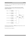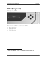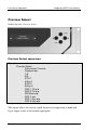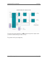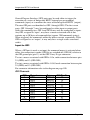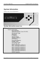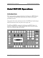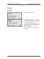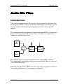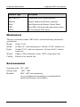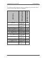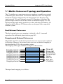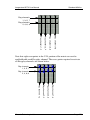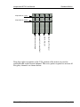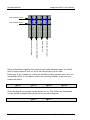
1
Imagestore HDTV User Manual 02901-1.13.6 May-2007 Software version 1.13.6 Miranda Technologies Ltd. UK Tel: +44 (0) 1491 820000 Fax: +44 (0) 1491 820001 Email: [email protected] Web: www.miranda.com Preface Imagestore HDTV User Manual Copyright © 1999 - 2007 Miranda Technologies Ltd. All rights are reserved and, under the copyright laws, this manual may not be reproduced in any form, in whole or in part, without the prior written consent of Miranda Technologies Ltd. Printed in the UK. Page 2 Miranda Technologies Ltd Imagestore HDTV User Manual Preface Preface Warranty Miranda Technologies Ltd offer a 24 months free parts and labour warranty on Oxtel Series equipment from the date of the initial invoice, providing there is no evidence of negligence, abuse or failure to reasonably follow instructions given by the Company for its proper use. During the warranty period, Miranda Technologies Ltd will replace or repair at its cost, Oxtel Series equipment returned to the factory, carriage and duty paid and insured by the sender. Before returning any item for warranty repair, a valid returns authorisation must be granted by Miranda Technologies Ltd. All repaired goods will be delivered (as instructed) carriage and duty paid and insured by the sender. Any warranty, over and above that offered here, is the responsibility of the local Miranda Sales Office or appointed Distributor. Contact Information For service, repair and warranty information and for returns authorisation contact: [email protected] Miranda Technologies Ltd Page 3 Preface Imagestore HDTV User Manual Important Safety Notices Injury Precautions 1. Use a proper power cable. To avoid fire hazard, use only an appropriate power cable which complies with the following: For mains connection use only a 10amp IEC inlet lead meeting EN60320 or equivalent. Connection to the mains supply should be via a circuit breaker or by a mains plug which meets the relevant local standards in the country of installation. 2. Avoid electrical overload. To avoid electric shock or fire hazard, do not apply a voltage to a terminal that is outside the range specified for that terminal. 3. Ground the product. Imagestore HDTV is grounded through the grounding conductor of the power cable. To avoid electrical shock, the grounding conductor must be connected to earth ground. Before making connections to the input or output terminals of Imagestore HDTV, ensure that the product is properly grounded. 4. Do not operate without the covers. To avoid electrical shock or fire hazard, do not operate Imagestore HDTV with its covers removed. 5. Use an appropriate fuse. To avoid fire hazard, use only the fuse type and rating specified for Imagestore HDTV. 6. Do not operate in wet/damp conditions. To avoid electrical shock, do not operate Imagestore HDTV in wet or damp conditions. Page 4 Miranda Technologies Ltd Imagestore HDTV User Manual Preface 7. Do not operate in an explosive atmosphere. To avoid injury or fire hazard, do not operate Imagestore HDTV in an explosive atmosphere. Product Damage Precautions 8. Provide proper ventilation. To prevent Imagestore HDTV overheating, provide proper ventilation. 9. Do not operate with suspected failures. If you suspect there is damage to Imagestore HDTV, have it inspected by qualified service personnel. Certifications and Compliances Imagestore HDTV has CE approval and complies with the standards detailed in EN50082-1:1992 and BS EN 60950:1992 Amd 3. Imagestore HDTV is fully Year 2000 millennium compliant. Miranda Technologies Ltd Page 5 Preface Imagestore HDTV User Manual Scope of the Manual The manual includes all the information required to install, configure and operate Imagestore HDTV. Serial automation control protocol used by Miranda Technologies Ltd mixers, keyers and still-store products is outside the scope of this manual. Details of this protocol and other related issues are found in the appropriate documents shown in the following list. Associated Publications Oxtel Series Automation Protocol MCS User Manual Textbuilder User Manual Part No. 01035 Part No. 01033 Part No. 02735 Electronic copies of the manuals are available from the Miranda website at: http://www.miranda.com/library.en/Automation%20Protocol/ and http://www.miranda.com/software.php Page 6 Miranda Technologies Ltd Imagestore HDTV User Manual Preface Symbols and Conventions Front panel control of Imagestore HDTV is achieved using four keys in conjunction with prompts from the display. Where reference is made to a key the legend of the key will be shown in lowercase italics (escape or enter) or by the icons ⊳ and . The two-line display provides a range of prompts in response to key presses. Where reference is made to an actual display prompt this will be shown italicised, e.g. Operate or Mix A Input. These symbols denote ‘Refer to documentation’. Miranda Technologies Ltd Page 7 Preface Imagestore HDTV User Manual Contacts For technical assistance, please contact your nearest Miranda Technical Support centre: Americas Telephone (9:00am - 9:00pm EST) +1-800-224-7882 [email protected] Asia Telephone (9:30am - 5:30pm JST) +81-3-5730-2987 [email protected] Europe, Middle East, Africa, UK Telephone (10:00am - 7:00pm CET) +44 (0) 1491 820222 [email protected] France (only) Telephone (9:00am - 6:00pm CET) Telephone: +33 (0) 1 55 86 87 88 [email protected] www.miranda.com Page 8 Miranda Technologies Ltd Imagestore HDTV User Manual Preface Manual Structure Overview The overview provides an introduction to the Miranda Technologies Ltd Imagestore HDTV for new users and describes the functions and features offered by the product. It includes a simple technical concept of the unit and details the optional modules that are available to enhance the unit's capabilities. Front Panel Operations This section describes how to operate Imagestore HDTV using the frontpanel controls. Each manual function, feature and parameter is fully described. Oxtel HD RCP This section describes how to operate Imagestore HDTV using the HD remote control panel. Each manual function, feature and parameter is fully described. Audio Mix files The mix file is used to specify sets of audio sources or inputs to be mixed together using certain rules and then assigning the result to a particular destination or output. This section explains the function and terminology of the mix file and how to create them. Emergency Alert System This section describes how to operate the Emergency Alert System. Imagestore Intuition This section describes how to configure the Imagestore for use with Intuition. Miranda Technologies Ltd Page 9 Preface Imagestore HDTV User Manual Installation This section contains details of the unit interconnections and interfaces. It describes all the set-up procedures required for a successful installation including reference source selection, internal timing and synchronisation setup. Support The support section describes the procedures for using the return-to-base warranty. It explains how to contact the Miranda Technologies Ltd technical support team and outlines a series of preliminary unit checks that should be made prior to calling. Product Specification This appendix provides a summary of the specifications of Imagestore HDTV. Glossary This appendix contains a guide to the terms and abbreviations found within this user guide. Standard mixfiles This section explains the operational differences implemented by each of the Miranda Technologies supplied Audio Mix files. Software Update Instructions on how to format a bootable floppy drive and to load the latest software. Menu Tree This appendix contains a listing of the current menu tree. Page 10 Miranda Technologies Ltd Imagestore HDTV User Manual Preface Index This appendix provides blank pages that may be used to record useful unit configuration data. Miranda Technologies Ltd Page 11 Preface Imagestore HDTV User Manual Page 12 Miranda Technologies Ltd Imagestore User Manual Table of Contents Table of Contents Contents Preface 3 Warranty --------------------------------------------------------------------------- 3 Important Safety Notices ------------------------------------------------------- 4 Injury Precautions-------------------------------------------------------------- 4 Product Damage Precautions ---------------------------------------------- 5 Certifications and Compliances -------------------------------------------- 5 Scope of the Manual ------------------------------------------------------------ 6 Associated Publications ------------------------------------------------------ 6 Symbols and Conventions ----------------------------------------------------- 7 Contacts ---------------------------------------------------------------------------- 8 Manual Structure ----------------------------------------------------------------- 9 Overview ------------------------------------------------------------------------- 9 Front Panel Operations------------------------------------------------------- 9 Oxtel HD RCP ------------------------------------------------------------------ 9 Audio Mix files ------------------------------------------------------------------ 9 Emergency Alert System----------------------------------------------------- 9 Imagestore Intuition ----------------------------------------------------------- 9 Installation --------------------------------------------------------------------- 10 Support ------------------------------------------------------------------------- 10 Product Specification ------------------------------------------------------- 10 Glossary------------------------------------------------------------------------ 10 Standard mixfiles------------------------------------------------------------- 10 Software Update ------------------------------------------------------------- 10 Menu Tree --------------------------------------------------------------------- 10 Index ---------------------------------------------------------------------------- 11 Table of Contents 13 Overview 29 Miranda Technologies Ltd Page 13 Table of Contents Imagestore HDTV User Manual Introduction-----------------------------------------------------------------------29 Applications ----------------------------------------------------------------------29 Concept ---------------------------------------------------------------------------29 Block Diagram-----------------------------------------------------------------30 Video Standards ----------------------------------------------------------------31 Getting Started ------------------------------------------------------------------31 Applying Power ---------------------------------------------------------------31 Boot-Up Sequence -----------------------------------------------------------32 Facilities and Features --------------------------------------------------------32 Image Loading and Distribution -------------------------------------------32 Image Editing ------------------------------------------------------------------33 Transmission ------------------------------------------------------------------33 Animated Images -------------------------------------------------------------33 AB Mixer ------------------------------------------------------------------------34 Timing, Control and Automation ------------------------------------------34 Mechanical Bypass ----------------------------------------------------------35 Emergency Alert System ---------------------------------------------------35 Dual 2D DVE ------------------------------------------------------------------35 Clock Insertion ----------------------------------------------------------------35 Embedded Digital Audio Mixer --------------------------------------------36 Digital Audio Storage --------------------------------------------------------36 Options --------------------------------------------------------------------------36 Checking Installed Options ----------------------------------------------38 Front Panel Display---------------------------------------------------38 Front Panel Operations 39 Controls -------------------------------------------------------------------------39 VFD Display--------------------------------------------------------------------39 VFD tallies -------------------------------------------------------------------40 Escape and Enter Keys -----------------------------------------------------40 Left and Right Arrow Keys (⊳ )-----------------------------------------40 Opening screen ---------------------------------------------------------------41 Operate ---------------------------------------------------------------------------42 Set Inputs-----------------------------------------------------------------------42 Set Inputs menu tree------------------------------------------------------42 Page 14 Miranda Technologies Ltd Imagestore HDTV User Manual Table of Contents Standard Colours --------------------------------------------------------- 43 Mix A Input -------------------------------------------------------------------- 44 Mix A Input menu tree --------------------------------------------------- 44 Mix B Input -------------------------------------------------------------------- 46 Mix B Input menu tree --------------------------------------------------- 46 AB Mixer ----------------------------------------------------------------------- 48 AB Mixer menu tree ------------------------------------------------------ 48 Cut AB ----------------------------------------------------------------------- 50 Cut To A--------------------------------------------------------------------- 50 Cut To B--------------------------------------------------------------------- 50 Fade AB --------------------------------------------------------------------- 50 Fade To A------------------------------------------------------------------- 50 Fade To B------------------------------------------------------------------- 50 Transition Type. ----------------------------------------------------------- 50 Mix Rate. -------------------------------------------------------------------- 51 V-Fade Colour. ------------------------------------------------------------ 51 Standard Colours----------------------------------------------------- 51 Set Cut Mode -------------------------------------------------------------- 52 Set Fade Mode ------------------------------------------------------------ 52 Dual 2D DVE------------------------------------------------------------------ 53 Dual 2D DVE menu tree------------------------------------------------- 53 Play Forward --------------------------------------------------------------- 54 Play Backward ------------------------------------------------------------- 54 Select Sequence ---------------------------------------------------------- 54 Video and embedded audio delay through the DVEs ------------ 54 DVE Mode ------------------------------------------------------------------ 54 Bypass ------------------------------------------------------------------ 54 None (Delay) ---------------------------------------------------------- 55 A B over DSK1-------------------------------------------------------- 55 AB Mixer---------------------------------------------------------------- 55 Mode diagrams ------------------------------------------------------------ 55 DSK 1 (Midground) ---------------------------------------------------------- 57 Keyer Operations --------------------------------------------------------- 58 Keyer Operations menu tree ------------------------------------------- 59 Cut Keyer Up/Down ------------------------------------------------- 60 Cut Keyer Up ---------------------------------------------------------- 60 Cut Keyer Down ------------------------------------------------------ 60 Fade Keyer Up/Down ----------------------------------------------- 60 Fade Keyer Up-------------------------------------------------------- 61 Miranda Technologies Ltd Page 15 Table of Contents Imagestore HDTV User Manual Fade Keyer Down-----------------------------------------------------61 Fade Rate---------------------------------------------------------------61 Set Key Parameters --------------------------------------------------61 Source ----------------------------------------------------------------63 Type -------------------------------------------------------------------63 Sense -----------------------------------------------------------------63 Clip, Gain & Trans ----------------------------------------------------64 Clip --------------------------------------------------------------------64 Gain -------------------------------------------------------------------64 Transparency -------------------------------------------------------64 Typical CGT Values -----------------------------------------------64 Cut To/From Black----------------------------------------------------64 Cut From Black --------------------------------------------------------64 Cut To Black -----------------------------------------------------------65 Fade To/From Black--------------------------------------------------65 Fade From Black ------------------------------------------------------65 Fade To Black ---------------------------------------------------------65 FTB Rate----------------------------------------------------------------65 Input Operations -----------------------------------------------------------66 Input Operations menu tree ---------------------------------------------66 Fill-1(2)/Key-1(2) ------------------------------------------------------66 Unload Input------------------------------------------------------------66 Store Operations-----------------------------------------------------------67 Store Operations menu tree---------------------------------------------67 Load Image-------------------------------------------------------------68 Set Position-------------------------------------------------------------68 Horizontal ------------------------------------------------------------68 Vertical----------------------------------------------------------------68 Set Masking ------------------------------------------------------------68 Disable----------------------------------------------------------------68 Setup------------------------------------------------------------------69 Left---------------------------------------------------------------------69 Right-------------------------------------------------------------------69 Top --------------------------------------------------------------------69 Bottom ----------------------------------------------------------------69 Save Image-------------------------------------------------------------69 Unload Image ----------------------------------------------------------69 Image Load Mode ----------------------------------------------------69 Clean Load ----------------------------------------------------------69 Page 16 Miranda Technologies Ltd Imagestore HDTV User Manual Table of Contents Cut Load------------------------------------------------------------- 69 Start Strap-------------------------------------------------------------- 70 Stop Strap-------------------------------------------------------------- 70 Start Timer ------------------------------------------------------------- 70 Stop Timer ------------------------------------------------------------- 70 Reset Timer------------------------------------------------------------ 70 Play Animation -------------------------------------------------------- 70 Restart Animation ---------------------------------------------------- 70 Stop Animation-------------------------------------------------------- 70 Stop Anim Instant ---------------------------------------------------- 70 DSK 2 (Foreground)--------------------------------------------------------- 71 Preview Select---------------------------------------------------------------- 72 Preview Select menu tree----------------------------------------------- 72 Audio---------------------------------------------------------------------------- 74 Audio menu tree----------------------------------------------------------- 74 Cut A/B------------------------------------------------------------------ 84 Cut to A ----------------------------------------------------------------- 84 Cut to B ----------------------------------------------------------------- 84 Fade A/B --------------------------------------------------------------- 84 Fade to A --------------------------------------------------------------- 84 Fade to B --------------------------------------------------------------- 85 Toggle Silence -------------------------------------------------------- 85 Fade to Silence ------------------------------------------------------- 85 Fade from Silence---------------------------------------------------- 85 Toggle VO-------------------------------------------------------------- 85 Voice-over n -------------------------------------------------------- 85 Fade up VO------------------------------------------------------------ 85 Voice-over n -------------------------------------------------------- 85 Fade down VO -------------------------------------------------------- 85 Voice-over n -------------------------------------------------------- 85 Select Preview -------------------------------------------------------- 85 Input Shuffles---------------------------------------------------------- 86 Set Rates--------------------------------------------------------------- 87 Fade A/B ------------------------------------------------------------ 87 Fade to Silence ---------------------------------------------------- 87 Voice-over n -------------------------------------------------------- 87 Voice-overs ------------------------------------------------------------ 87 Duck ------------------------------------------------------------------ 88 Preset ---------------------------------------------------------------- 88 Miranda Technologies Ltd Page 17 Table of Contents Imagestore HDTV User Manual Easyplay ----------------------------------------------------------------88 Store n ----------------------------------------------------------------88 GPI Output ---------------------------------------------------------------------90 GPI Output Menu Tree ---------------------------------------------------90 GPI Output--------------------------------------------------------------90 Miscellaneous -----------------------------------------------------------------92 Miscellaneous menu tree ------------------------------------------------92 GPI Macro Delay ------------------------------------------------------92 Emergency To Air-----------------------------------------------------93 Emergency From Air -------------------------------------------------93 EAS On------------------------------------------------------------------93 EAS Off------------------------------------------------------------------93 Setup ------------------------------------------------------------------------------94 Audio Setup --------------------------------------------------------------------94 Audio Setup menu tree ---------------------------------------------------94 Audio Metering --------------------------------------------------------95 Meters 1 to 4 --------------------------------------------------------95 Meters 1 and 2------------------------------------------------------96 Follow Video -----------------------------------------------------------96 A/B Mix ---------------------------------------------------------------96 Fade-to-Black -------------------------------------------------------96 Easyplay -------------------------------------------------------------96 Select Mixfile -----------------------------------------------------------96 Delays -------------------------------------------------------------------97 GPI Setup ----------------------------------------------------------------------98 GPI Setup menu tree -----------------------------------------------------98 Input to GPI -----------------------------------------------------------------99 GPI Channels ----------------------------------------------------------99 Create a GPI Macro----------------------------------------------------- 100 GPI Macro Command list ---------------------------------------------- 100 Set Inputs ------------------------------------------------------------- 100 Mix A Input------------------------------------------------------------ 101 Mix B Input------------------------------------------------------------ 101 AB Mixer -------------------------------------------------------------- 101 Dual 2D DVE--------------------------------------------------------- 102 DSK 1 ------------------------------------------------------------------ 102 DSK 2 ------------------------------------------------------------------ 103 Preview Select ------------------------------------------------------- 105 Page 18 Miranda Technologies Ltd Imagestore HDTV User Manual Table of Contents Audio -------------------------------------------------------------------105 GPI Output ------------------------------------------------------------112 Miscellaneous --------------------------------------------------------112 Edit a GPI Macro ---------------------------------------------------------112 Insert Before----------------------------------------------------------112 Delete ------------------------------------------------------------------112 Insert After ------------------------------------------------------------113 Output from GPI ----------------------------------------------------------113 Create a GPI output -----------------------------------------------------113 Clear a GPI output -------------------------------------------------------114 Show GPI Inputs ---------------------------------------------------------114 Faders Set Up ---------------------------------------------------------------115 Fader Set-Up menu tree -----------------------------------------------115 Configuration --------------------------------------------------------------117 Fader------------------------------------------------------------------------117 ADC Channels -------------------------------------------------------117 Enable Control ------------------------------------------------------------118 Invert Control--------------------------------------------------------------118 Enable Pickup ------------------------------------------------------------118 Show Fader Inputs-------------------------------------------------------118 File Operations --------------------------------------------------------------119 File Operations menu tree ---------------------------------------------119 Load Image File ----------------------------------------------------------120 Erase Image---------------------------------------------------------------120 Load Audio File -----------------------------------------------------------120 Erase Audio File----------------------------------------------------------120 Configuration Save ------------------------------------------------------120 Configuration Load ------------------------------------------------------121 Diagnostic Save ----------------------------------------------------------121 Load System Codes-----------------------------------------------------121 Load Mixfile----------------------------------------------------------------121 Erase Mixfile --------------------------------------------------------------121 System Information---------------------------------------------------------122 System Information menu tree----------------------------------------122 Serial Number ------------------------------------------------------------123 Operating System--------------------------------------------------------123 File System Type---------------------------------------------------------123 Hostname ------------------------------------------------------------------123 IP Address -----------------------------------------------------------------124 Miranda Technologies Ltd Page 19 Table of Contents Imagestore HDTV User Manual Network Mask ------------------------------------------------------------ 124 Gateway Address-------------------------------------------------------- 124 NTP Server---------------------------------------------------------------- 124 Animation Memory ------------------------------------------------------ 124 Images Used-------------------------------------------------------------- 124 Disk Space Used -------------------------------------------------------- 124 Current Mix File ---------------------------------------------------------- 124 Slot 1-6 --------------------------------------------------------------------- 125 RS232 Counters --------------------------------------------------------- 125 RS422 A-B Counters --------------------------------------------------- 125 Internal Temp ------------------------------------------------------------- 125 -12V Supply --------------------------------------------------------------- 126 +1.8V Supply ------------------------------------------------------------- 126 +3.3V Supply ------------------------------------------------------------- 126 +5.0V Supply ------------------------------------------------------------- 126 +2.5V Supply ------------------------------------------------------------- 126 +12V Supply -------------------------------------------------------------- 126 Time Zone ----------------------------------------------------------------- 126 Current Time -------------------------------------------------------------- 126 Running Since ------------------------------------------------------------ 126 View Licences --------------------------------------------------------------- 127 Set Time of Day------------------------------------------------------------- 127 Set Time-of-Day menu tree ------------------------------------------- 128 Year ------------------------------------------------------------------------- 128 Month ----------------------------------------------------------------------- 128 Day -------------------------------------------------------------------------- 128 Hour ------------------------------------------------------------------------- 128 Min -------------------------------------------------------------------------- 128 Sec -------------------------------------------------------------------------- 128 Self Tests --------------------------------------------------------------------- 129 Self Tests menu tree---------------------------------------------------- 129 DSK 1----------------------------------------------------------------------- 129 Image Border -------------------------------------------------------- 129 Animation Fill--------------------------------------------------------- 130 DSK 2----------------------------------------------------------------------- 131 EAS ------------------------------------------------------------------------- 131 Severity 1 ------------------------------------------------------------------ 131 Severity 2 ------------------------------------------------------------------ 131 Severity 3 ------------------------------------------------------------------ 131 Page 20 Miranda Technologies Ltd Imagestore HDTV User Manual Table of Contents Logging------------------------------------------------------------------------132 Logging menu tree-------------------------------------------------------132 Errors Only ----------------------------------------------------------------132 Media/Keying -------------------------------------------------------------132 Verbose --------------------------------------------------------------------132 System Setup -------------------------------------------------------------133 System Setup menu tree-----------------------------------------------133 Set Standard --------------------------------------------------------------135 Select Reference---------------------------------------------------------136 PGM wrt (with respect to) HD/REF1----------------------------136 PGM wrt SD/REF2 --------------------------------------------------136 PGM wrt 1/A ----------------------------------------------------------136 Adjusting reference timing ----------------------------------------136 Timing delay through the Imagestore HDTV -----------------138 Serial Comms Setup ----------------------------------------------------138 Presmaster------------------------------------------------------------138 Easysound ------------------------------------------------------------138 Intuition ----------------------------------------------------------------138 EAS ---------------------------------------------------------------------138 Automation------------------------------------------------------------139 Timecode Options -------------------------------------------------------139 Timecode Source ---------------------------------------------------139 Timecode Status ----------------------------------------------------139 Intuition Setup ------------------------------------------------------------139 Def Keyer Assign----------------------------------------------------139 None-----------------------------------------------------------------139 DSK1 ----------------------------------------------------------------140 DSK2 ----------------------------------------------------------------140 Keyer Release Mode -----------------------------------------------140 Disabled ------------------------------------------------------------140 Enabled -------------------------------------------------------------140 Keyer Status----------------------------------------------------------140 Hostname ------------------------------------------------------------------140 IP Address -----------------------------------------------------------------141 Network Mask-------------------------------------------------------------142 Gateway Address --------------------------------------------------------142 NTP Server ----------------------------------------------------------------143 Time Zone -----------------------------------------------------------------143 Console Blanking --------------------------------------------------------143 Miranda Technologies Ltd Page 21 Table of Contents Imagestore HDTV User Manual Restart System ----------------------------------------------------------- 143 Factory Reset------------------------------------------------------------- 144 Safe Shutdown ----------------------------------------------------------- 144 Oxtel RCP-HD Operations 145 Introduction--------------------------------------------------------------------- 145 Controls ------------------------------------------------------------------------- 146 Display -------------------------------------------------------------------------- 146 Push Button Switches ------------------------------------------------------- 146 Esc Key ----------------------------------------------------------------------- 146 Input Router Select 1-6 Keys -------------------------------------------- 147 Alphanumeric Keypad ----------------------------------------------------- 147 Setup Menu ------------------------------------------------------------------ 147 Video Menu ------------------------------------------------------------------ 148 Mixer ------------------------------------------------------------------------ 148 Transition type ------------------------------------------------------- 148 Rate -------------------------------------------------------------------- 149 DSK# ----------------------------------------------------------------------- 150 Input source ---------------------------------------------------------- 150 Load file --------------------------------------------------------------- 151 Position file ----------------------------------------------------------- 152 Horizontal Crop ------------------------------------------------------ 153 Vertical Crop --------------------------------------------------------- 154 Save file --------------------------------------------------------------- 155 Clip Gain & Transparency ---------------------------------------- 156 Keying Modes-------------------------------------------------------- 157 Fade to Black rate ------------------------------------------------------- 158 Audio Menu ------------------------------------------------------------------ 159 Transitions----------------------------------------------------------------- 159 A/B Mix ---------------------------------------------------------------- 159 Fade to Silence ------------------------------------------------------ 160 Voice Overs ---------------------------------------------------------- 161 Inputs ----------------------------------------------------------------------- 162 A, B, VO1, VO2------------------------------------------------------ 162 Outputs --------------------------------------------------------------------- 163 Program --------------------------------------------------------------- 163 Page 22 Miranda Technologies Ltd Imagestore HDTV User Manual Table of Contents Transitions --------------------------------------------------------------------164 Rate -------------------------------------------------------------------------164 Mixer ------------------------------------------------------------------------165 Selecting the source ------------------------------------------------165 cut-----------------------------------------------------------------------165 trans --------------------------------------------------------------------165 DSK 1 -----------------------------------------------------------------------166 cut-----------------------------------------------------------------------166 trans --------------------------------------------------------------------166 DSK 2 -----------------------------------------------------------------------166 Take----------------------------------------------------------------------------167 Black and Silence-----------------------------------------------------------167 Voice-Over 1 -----------------------------------------------------------------167 Voice-Over 2 -----------------------------------------------------------------167 Chan Sel ----------------------------------------------------------------------167 Audio Mix Files 169 Introduction ---------------------------------------------------------------------169 Mix Files -------------------------------------------------------------------------170 Sources--------------------------------------------------------------------------171 Gain Types ---------------------------------------------------------------------171 ZERO_XP --------------------------------------------------------------------172 UNITY_XP --------------------------------------------------------------------172 A_DATA_XP/B_DATA_XP -----------------------------------------------172 A_XP/B_XP ------------------------------------------------------------------172 VO1_XP/VO3_XP ----------------------------------------------------------172 EPLAY_XP -------------------------------------------------------------------172 A_UNITY_XP/B_UNITY_XP ---------------------------------------------173 VO1_UNITY_XP/VO3_UNITY_XP -------------------------------------173 Output Gain Types------------------------------------------------------------173 PROGRAM_GAIN ----------------------------------------------------------173 Destinations --------------------------------------------------------------------173 Mix File Commands ----------------------------------------------------------174 StartMix -----------------------------------------------------------------------174 Miranda Technologies Ltd Page 23 Table of Contents Imagestore HDTV User Manual AddToMix--------------------------------------------------------------------- 174 SetOutputGain -------------------------------------------------------------- 174 OutputMix--------------------------------------------------------------------- 175 EndMix ------------------------------------------------------------------------ 175 Simple mix structure ------------------------------------------------------- 175 Input Bunches --------------------------------------------------------------- 175 Enhanced Mix File Commands-------------------------------------------- 177 Input Bunch Profiles ------------------------------------------------------- 177 MixDown ---------------------------------------------------------------------- 178 Monitor Profiles ------------------------------------------------------------- 179 Input Source names (AddToMix) ----------------------------------------- 180 Output Source names (OutputMix) --------------------------------------- 181 Mixfile mapping---------------------------------------------------------------- 183 Emergency Alert System 185 EAS Receivers -------------------------------------------------------------- 185 Baud Rates------------------------------------------------------------------- 186 Load EAS (EAS On) ------------------------------------------------------- 186 Unload EAS (EAS Off) ---------------------------------------------------- 186 EAS logs ---------------------------------------------------------------------- 186 Imagestore Intuition 187 Imagestore Intuition Control------------------------------------------------ 189 Control--------------------------------------------------------------------------- 190 Automatic Keyer Management -------------------------------------------- 190 Front Panel Menu ---------------------------------------------------------- 191 Def Keyer Assign -------------------------------------------------------- 191 None ------------------------------------------------------------------- 192 DSK1------------------------------------------------------------------- 192 DSK2------------------------------------------------------------------- 192 Keyer Release Mode --------------------------------------------------- 192 Disabled --------------------------------------------------------------- 192 Enabled---------------------------------------------------------------- 192 Keyer Status -------------------------------------------------------------- 192 Page 24 Miranda Technologies Ltd Imagestore HDTV User Manual Table of Contents Keyer Management example --------------------------------------------193 Pitfalls-----------------------------------------------------------------------193 Installation 195 Ventilation-----------------------------------------------------------------------195 Power Requirements---------------------------------------------------------195 Environment--------------------------------------------------------------------195 Cabling --------------------------------------------------------------------------195 HDTV Rear Panel Connections -------------------------------------------197 PCI Connectors -------------------------------------------------------------197 RS422(A/B)----------------------------------------------------------------197 Oxtel RCP -----------------------------------------------------------------198 RS232 ----------------------------------------------------------------------198 GPI --------------------------------------------------------------------------199 VGA and KBD Connections -------------------------------------------200 VGA --------------------------------------------------------------------200 KBD---------------------------------------------------------------------201 LAN 2 -----------------------------------------------------------------------201 REF 1 / 2 -------------------------------------------------------------------202 Connection of LTC or VITC ----------------------------------------------202 Mains Input ----------------------------------------------------------------202 HD-SDI source inputs---------------------------------------------------203 Input options----------------------------------------------------------203 Video Relay Bypass -----------------------------------------------------204 Connection of Analogue Faders-----------------------------------------204 Connection of General Purpose Interfaces (GPI’s)-----------------205 Input to GPI----------------------------------------------------------------205 Output from GPI ----------------------------------------------------------205 Audio connections ----------------------------------------------------------206 AES IN (1:8) ---------------------------------------------------------------206 IS2 Mode AES input connector pin-out ------------------------206 AES IN (9:16) -------------------------------------------------------------206 AES OUT (1:8)------------------------------------------------------------207 IS2 Mode AES output connector pin-out ----------------------207 AES IN (9:16) -------------------------------------------------------------207 Miranda Technologies Ltd Page 25 Table of Contents Imagestore HDTV User Manual Rear panel connections ------------------------------------------------ 208 Audio AES IN ------------------------------------------------------------- 209 Audio AES OUT---------------------------------------------------------- 210 Rear panel slots------------------------------------------------------------- 211 Support 213 Product Support--------------------------------------------------------------- 213 Warranty and Non-Warranty Repairs ---------------------------------- 214 Obsolescence --------------------------------------------------------------- 214 Upgrades --------------------------------------------------------------------- 214 Service Visits ---------------------------------------------------------------- 214 Equipment Loans ----------------------------------------------------------- 215 Training ----------------------------------------------------------------------- 215 Web Page -------------------------------------------------------------------- 215 Returns Procedure ----------------------------------------------------------- 215 Transit Packaging ---------------------------------------------------------- 215 Imagestore Specifications 217 HD-SDI Inputs and Outputs ---------------------------------------------- 217 Power Requirements ------------------------------------------------------ 217 Interfaces --------------------------------------------------------------------- 217 Mechanical ------------------------------------------------------------------- 218 Environmental --------------------------------------------------------------- 218 Glossary 219 Standard Mixfiles 221 Introduction--------------------------------------------------------------------- 221 IS2/3 Emulation Mixfiles ---------------------------------------------------- 226 is23.mix & is23eply.mix --------------------------------------------------- 226 Program output meter tracking --------------------------------------- 226 Voice-over preview meter tracking ---------------------------------- 226 12 channel pass-through ---------------------------------------------- 226 Group sensitive previewing ------------------------------------------- 226 Page 26 Miranda Technologies Ltd Imagestore HDTV User Manual Table of Contents Pass-through Mixfiles --------------------------------------------------------227 16chn_pass.mix -------------------------------------------------------------227 16chn_AES_pass.mix -----------------------------------------------------227 16 Channel AB Mixfiles------------------------------------------------------227 16chn_AB.mix ---------------------------------------------------------------228 16chn_AB_eply.mix --------------------------------------------------------228 5.1 Channel Mixfiles----------------------------------------------------------229 Introduction -------------------------------------------------------------------229 Mix Modes -----------------------------------------------------------------229 Versatile Voice-over Shuffling ----------------------------------------229 Preview Modes and Metering -----------------------------------------230 Delay Banks for DVE Compensation--------------------------------230 10 Channel Pass-through----------------------------------------------230 5.1 Mixfile Variants ---------------------------------------------------------231 5.1_dualVO.mix ----------------------------------------------------------231 5.1_VO_eply.mix ---------------------------------------------------------231 5.1_AES_dualVO.mix---------------------------------------------------231 5.1_AES_VO_eply.mix -------------------------------------------------232 5.1_IntuitionVO.mix------------------------------------------------------232 5.1 Mix Modes ---------------------------------------------------------------232 Mode 1: Standard 5.1 AB mix-----------------------------------------232 Mode 2: Left and Right Copy------------------------------------------234 Mode 3: Left, Right and Centre Copy -------------------------------239 5.1 Mixfile Voice-over Topology and Operation ---------------------242 Dual External Voice-overs ---------------------------------------------242 Easyplay and External Voice-over -----------------------------------246 6-channel External Voice-over (Intuition+)-------------------------250 7.1 Channel Mixfiles----------------------------------------------------------253 Introduction -------------------------------------------------------------------253 Mix Modes -----------------------------------------------------------------253 Versatile Voice-over Shuffling ----------------------------------------254 Preview Modes and Metering -----------------------------------------254 Delay Banks for DVE Compensation--------------------------------254 8 Channel Pass-through -----------------------------------------------254 7.1 Mixfile Variants ---------------------------------------------------------255 7.1_dualVO.mix ----------------------------------------------------------255 7.1_VO_eply.mix ---------------------------------------------------------255 Miranda Technologies Ltd Page 27 Table of Contents Imagestore HDTV User Manual 7.1_ AES_eply.mix ------------------------------------------------------ 255 7.1_IntuitionVO.mix ----------------------------------------------------- 256 7.1 Mixfile Modes ----------------------------------------------------------- 256 Mode 1: Standard 7.1 AB mix ---------------------------------------- 256 Mode 2: AB Mix Left and Right Copy ------------------------------- 257 Mode 3: Left, Right and Centre Mix --------------------------------- 257 7.1 Mixfile Voice-over Topology and Operation --------------------- 258 Dual External Voice-over ---------------------------------------------- 258 Easyplay and External Voice-over----------------------------------- 258 8-channel External Voice-over (Intuition+) ------------------------ 260 Test Mixfiles-------------------------------------------------------------------- 263 test_eply.mix----------------------------------------------------------------- 263 testtone_all.mix ------------------------------------------------------------- 263 Software Update 265 Create Bootable Floppy from Update ZIP File----------------------- 265 1. Updating from v1.11.x (or earlier) via front panel------------- 265 2. Updating from v1.13.x (or later) via web page ---------------- 265 Update Software with CPIO Archive ----------------------------------- 267 Menu Tree 269 Index 283 Page 28 Miranda Technologies Ltd Imagestore HDTV User Manual Overview Overview Introduction This introduction provides a basic overview of the concept of the unit and includes instructions for getting started. An extensive range of options and upgrades are available for Imagestore HDTV and this section describes the purpose and features of each enhancement. More detailed and specific information regarding operation, configuration, installation and support are provided in later sections. Imagestore HDTV (Product code IS-HDTV) is part of Miranda Technologies Ltd's professional broadcast equipment range of products and its primary use is to insert logos into a HD-SDI digital video signal. The capabilities of this 2U unit include simple logo insertion, still and animated images. Applications Imagestore HDTV is typically used to insert a still or animated logo, channel identification, a programme schedule, an advertisement, an emergency image, or a combination of any two of those. Each of these resources may be brought on-air from the 40-image library (optionally 400, 1000 or 2000 image). Alternatively, external 'live' fill and key signals from a character generator, or a still/animation store, can be directly inserted into the HD signal. Concept Imagestore HDTV is set up for operation where the two keyers are arranged in series as shown below. This configuration allows two images to be keyed simultaneously, but independently, over the background video. A fail-safe mechanical Video Relay Bypass option (VRB-HD-001) is available that directly connects the background video source to the programme output in the event of a power supply problem. Miranda Technologies Ltd Page 29 Overview Imagestore HDTV User Manual Still (.oxt), animated and Easytext (.oxa) images are typically stored in the unit's hard disk library. Images may be added to the library using the floppy disk drive but the files must be in an appropriate format. Miranda Technologies Ltd's Media Conversion Software is designed for this purpose and is supplied with each Imagestore HDTV. An Ethernet interface option (NET-HD-001) provides for the rapid loading of images and animations over either a co-axial or twisted pair network using MCS. This interface also enables the transference of images between a PC workstation and Imagestore using Miranda Technologies Ltd's Media Distribution System (MDS). The MDS software provides for transfer and management of still-images and animations. Files may also be transferred using an FTP program. Block Diagram Page 30 Miranda Technologies Ltd Imagestore HDTV User Manual Overview Video Standards Imagestore HDTV supports SMPTE 292M 1.485Gb/s at the following resolutions: 1920 x 1080i/59.94 Hz SMPTE 274M 1998 1920 x 1080i/50 Hz SMPTE 274M 1998 1280 x 720/59.94 Hz SMPTE 296M 2001 1280 x 720/50 Hz SMPTE 296M 2001 Standard SMPTE 274M 1920 x 1080/ 59.94/2:1 1920 x 1080/ 50/2:1 SMPTE 296M 1280 x 720/ 59.94 1280 x 720/ 50 Words per active line (S/AL) Active lines per frame Frame rate (Hz) Scanning format Interface sampling frequency Fs (MHz) Words per total line (S/TL) Total lines per frame 1920 1080 30/1.001 2:1 interlace 74.25/1.001 2200 1125 1920 1080 25 2:1 interlace 74.25 2640 1125 1280 720 60/1.001 74.25/1.001 1650 750 1280 720 50 1:1 Progressive 1:1 Progressive 74.25 1980 750 Getting Started Applying Power Before applying power, ensure that the floppy disk drive does not contain a disk. Imagestore HDTV does not have a power on/off switch and power is applied immediately when the IEC plug is connected to mains power. The product should be connected to the mains via an appropriate circuit breaker. In the event the second PSU option (PSU-HD-001) in not fitted always connect to the IEC socket labelled PSU1 first. Miranda Technologies Ltd Page 31 Overview Imagestore HDTV User Manual Boot-Up Sequence Once power is applied Imagestore HDTV will boot automatically and the complete process takes about 30 seconds. The unit first checks to see if there is a disk in the floppy drive and, if it finds one, it will attempt to boot from that disk. Miranda Technologies Ltd issues specialised floppy disks for use as part of the boot-up sequence when software upgrades are being implemented. No other disk should ever be present in the floppy disk drive during the boot sequence. The boot sequence is complete when the following top level "bootup" menu appears on the front panel VFD display. Facilities and Features Image Loading and Distribution The entry-level Imagestore HDTV provides storage for up to forty full-screen images with their associated keys and this can currently be upgraded to 400, 1000 or 2000 images. Each animated clip is counted as one single image stored in the library. With large or long duration animations (where the total pixel count of the animation exceeds one full-screen frame) the total number of full screen frames used counts towards the permitted maximum of fullscreen images in the library. Images (.oxt), animations and Easytest (.oxa) files saved to floppy disks from Miranda Technologies Ltd's Media Conversion Software - (or other Miranda Technologies Ltd units) can be loaded in the same way. The Media Page 32 Miranda Technologies Ltd Imagestore HDTV User Manual Overview Conversion software allows large animations and images to be saved across multiple floppy disks (span files .oxm), using loss-less compression to reduce the number of disks required. Miranda Technologies Ltd also provides an image transfer and management system for Imagestore HDTV. The Media Distribution System(MDS) uses a local area network to connect the workstation to a number of Miranda Technologies Ltd's image and audio insertion products. Details of MDS are contained in a separate manual user guide. Image Editing The image editor permits an operator to position an image/animation (both horizontally and vertically), mask the image/animation and adjust the clip, gain and transparency levels prior to transmission. Transmission Once prepared, an image/animation can be saved in the image library and sent to air using fade and cut transitions. Animated Images Imagestore HDTV provides image animation, for applications such as moving logos, messages and emergency images. The image motion system provides storage and live playout for up to 40, (optionally 400, 1000 or 2000) full, or part-screen images of variable duration. The maximum animation length is dependent upon both the screen-size of the images and the playout memory installed in the Imagestore HDTV. There are two video stores, which may be used to hold text, stills or moving logos. The images may be any size up to full screen. Stored images and their associated keys are stored and processed at 10 bit resolution. (Unless the image is stored without key to save space in which case it is stored at 8 bit resolution.) The time for larger animations, up to full screen, are reduced proportionally to the area used. Areas are evaluated each frame so bugs may change in size with no penalty. Miranda Technologies Ltd Page 33 Overview Imagestore HDTV User Manual With 256MB of playout memory, a logo of ¹/64 screen size can be animated for just over a minute. Larger screen sizes or smaller playout memory sizes affect the maximum animation time pro rata. Memory option 64 HDTV Rate Standard 1080i 59.94 Frame rate MB / frame 128 256 512 Max no. of frames 29.97 7.91 8.0 16.1 32.2 64.4 Duration (s) 1/16th frame > 4.3s 8.6s 17.2s 34.4s 1/64th frame > 17.0s 34.3s 68.8s 137.6s Moving images are constructed from component images using the animation builder software provided as part of the Media Conversion Software package supplied with Imagestore HDTV. Component images are imported into the animation builder utility from 32-bit Targa image files thus allowing components to originate from almost any computer graphics system. AB Mixer The optional integral AB Mixer (MIX-HD-001) video switcher is designed to be fed by any of the unit’s input sources or by an external router under automation control. The mixer provides cut, cross and V fade transitions with variable fade rates. Timing, Control and Automation Imagestore is designed to be easy to install. One line FIFO’s are provided on each input for simplified system timing. Other valuable set-up and control features include a menu-driven front panel VFD display, a General Purpose Interface (GPI) macro editor and a facility to load configuration settings from, and save system configurations to, a floppy disk. Page 34 Miranda Technologies Ltd Imagestore HDTV User Manual Overview Imagestore HDTV is highly suited to automated broadcast environments and remote control options include RS422/RS232, as well as GPI and analogue fader inputs. Mechanical Bypass In the event of power loss to the Imagestore HDTV, or failure of an internal power supply, the mechanical video relay bypass option (VRB-HD-001) routes the serial digital “background signal” directly to the programme output. This feature is an emergency failsafe and is completely nonsynchronous in operation. During boot-up, the bypass is maintained until Imagestore HDTV is fully operational. Emergency Alert System Imagestore HDTV supports Emergency Alert Systems providing the relevant licence is installed. The 2 EAS models supported are: ♦ Sage ENDEC Model 1822 ♦ TFT EAS 911T To configure a communication port to accept the EAS data stream refer to the Serial Comms Setup section on page 138. Dual 2D DVE IP2-HD-2DVE is a dual-channel 2D DVE option capable of digital video effects on both the A and B input video streams, making it ideal for picturein-picture applications such as over the shoulder news transitions, as well as squeezes for credits, news flashes, sports results and schedules. Clock Insertion The Bugclock option allows Imagestore HDTV to insert customised in-vision clocks. A wide range of clocks and timers can be generated, with hour, minute and second indications. Fully customised clocks can be produced offline using the Clock Builder (part of the MCS Media Conversion software package). Bugclock can be locked to station LTC or VITC timecode. Clocks Miranda Technologies Ltd Page 35 Overview Imagestore HDTV User Manual are loaded, previewed, positioned and keyed in the same way as animations and static logos. Bugclock images behave like all other images with respect to positioning, transparency and masking controls. Previewing behaviour is the same as with other clips and images and will show the clock running where appropriate All existing GPI and automation commands, that apply to still images and animations, function identically for clocks. Bugclocks like other images use a single keying layer. This means that a clock can be previewed while a different clock is shown on programme. Embedded Digital Audio Mixer The optional Easysound digital audio mixer (ES-HD-8) can be fitted within Imagestore HDTV and is designed to add voice-overs, jingles and other audio inserts over a programme soundtrack at transmission. Easysound can also accept audio from AES/EBU sources, as well as embedded audio from the Imagestore's background video input. The four mixes are available on AES/EBU outputs and can also be re-embedded into the SDI programme output. Digital Audio Storage Easyplay (EP-HD-001) is the digital audio storage and playout option for Imagestore HDTV. With Easyplay, broadcasters can associate sounds to image files, creating a whole new range of possibilities for musical logos and sound enhanced captions. Easyplay requires the Easysound option to be fitted to Imagestore HDTV and the system may be networked with the Media Distribution System. Options Status information regarding the options included with each Imagestore HDTV can be accessed from the front panel display, using the panel control keys as described later in this guide. The following table lists the options with their identifying codes and briefly describes the purpose. Page 36 Miranda Technologies Ltd Imagestore HDTV User Manual Overview Option MEM-HD400V Description Image Library expansion to 400 frames with 2 x 128MB playout memory. MEM-HD1000V Image Library expansion to 1000 frames with 2 x 256MB playout memory. MEM-HD2000v Image Library expansion to 2000 frames with 2 x 512MB playout memory. MIX-HD-001 A/B video mixer IP2-HD-001 2 video input option. Replaces standard single input board. Note a maximum of 3 IP2-HD-001 boards can be fitted. IP2-HD2DVE 2 channel DVE board. Replaces standard input board VRB-HD-001 Mechanical Video Relay Bypass PSU-HD-001 Dual power supply option NET-HD-001 10/100MB Ethernet interface RJ45 MDS-002HD Media Distribution System (requires NET-002 Option). EAS-HD-001 Emergency Alert System support ET-HD-001 BCK-HD-001 Easytext automated character generator On screen analogue and digital clocks ES-HD-8 Digital Audio mixer board with 32 channels (16 stereo pairs) AES I/O processing EP-HD-001 Digital Audio storage and playout option ES-HDEMBED1-8 Audio embedding / de-embedding on channels 1-8 ES-HDEMBED9-19 Audio embedding / de-embedding on channels 9-16 LOGO-HD Imagestore Logo Inserter only Miranda Technologies Ltd Page 37 Overview Imagestore HDTV User Manual Checking Installed Options The Imagestore HDTV can display the internal options installed from the front panel display. Front Panel Display From the opening screen press the right arrow key to display Setup then press the enter key to display the Setup menu. Press the right arrow key until View Licenses appears on the second line of the display then press the enter key. Repeatedly pressing the key will now cycle the display through a list of the fitted options. When completed, press the escape key a few times until the boot-up menu reappears. Page 38 License Code AB Mixer Option A/B video mixer Ethernet 10/100 Ethernet Interface Image Lib:40 40 Image library (2 x 64MB) Image Lib:400 400 Image library (2 x 128MB) Image Lib:1000 1000 Image library (2 x 256MB) Image Lib:2000 2000 Image library (2 x 512MB) Emergency Alert Emergency Alert System Easytext Easytext Character Gen. Dual 2D DVE 2 channel DVE Easysound Digital Audio Mixer Easyplay Audio Lib:40 Digital Audio storage and playout 40 Audio Image library Audio Lib:400 400 Audio Image library Audio Lib:1000 1000 Audio Image library Audio Lib:2000 2000 Audio Image library Audio Embed:2 Audio Embedding on channels 1-8 Audio Embed:4 Audio Embedding on channels 1-16 Miranda Technologies Ltd Imagestore HDTV User Manual Front Panel Operations Front Panel Operations This section of the manual explains, on a task-by-task basis, the operation of an Imagestore HDTV using only the front panel controls. Each task is fully detailed, making reference to other sections unnecessary. Controls All of Imagestore HDTV's operational and configuration features can be monitored and controlled from the front panel of the unit using the pushbuttons and display. A simple menu-driven procedure provides access to the operational, configuration and set-up options. The front panel of Imagestore HDTV contains a 3½ floppy disk drive, four push-button control keys and a vacuum fluorescent display (VFD). Local control of the unit is "menu driven" using a combination of the push-button keys together with options displayed on the VFD. The upper key of the group is identified on the panel as the escape key and the bottom key is identified as the enter key. Left and right keys ⊳ are used to move a cursor left and right accordingly to select menu options. VFD Display The alphanumeric VFD display is divided into two separate lines. The upper row of characters indicating the function and the lower row indicating the current selection and any optional configuration changes that are available. Where there are more options available than there is room for on the display, the symbols ⊳ and are used to indicate that other options exist to the left Miranda Technologies Ltd Page 39 Front Panel Operations Imagestore HDTV User Manual and right respectively. Using the appropriate arrow key will reveal those options. If an option is not licenced, e.g. Dual 2D DVE, it will not be displayed on the front panel menu. VFD tallies To highlight the state of either the AB Mixer (video/audio) or the keyers, additional symbols are shown on the top line of the VFD display at the right hand edge. These symbols represent: A source A B source B intermediate state, transition being processed. ↑ image/voice-over keyed up (to air) ↓ B S image/voice-over keyed down (from air) Fade to Black Fade to Silent Escape and Enter Keys The escape key is used to proceed to a menu option closer to the boot-up menu. Successive pressing of the key will bring the display to the start-up menu. The enter key is used to accept the menu item currently shown as selected by being enclosed in brackets. Left and Right Arrow Keys (⊳ ) Left and right arrow keys ⊳ may be used to index left and right respectively along a displayed menu branch to select a function. When a selection of parameters is offered, these keys may be used to select a variable. Where a single value is displayed the left arrow key may be used to reduce the displayed value and the right key may be used to increase it. Page 40 Miranda Technologies Ltd Imagestore HDTV User Manual Overview Opening screen The Imagestore HDTV menu has two branches: Operate Setup From the opening screen with Operate displayed press the enter key. Miranda Technologies Ltd Page 41 Front Panel Operations Imagestore HDTV User Manual Operate Set Inputs Select Operate, Set Inputs. Set Inputs menu tree Operate Set Inputs 1/A Pass SDI Force Colour Field RGB 0 <> 100% Pass SDI Force Colour Field RGB 0 <> 100% Pass SDI Force Colour Field RGB 0 <> 100% Pass SDI Force Colour Field RGB 0 <> 100% Pass SDI Force Colour Field RGB 0 <> 100% 2/B 3/Fill-1 4/Key-1 5/Fill-2 Page 42 Miranda Technologies Ltd Imagestore HDTV User Manual Overview 6/Key-2 Pass SDI Force Colour Field RGB 0 <> 100% The factory default setting for each input is to Pass-SDI. If the input is unused/unconnected it can be set to internally generate a colour field. Using the front panel control keys (⊳ enter) select the input you wish to modify. To adjust the colour field select Force Colour Field then press the enter key. The colour field is set by adjusting the RGB (Red, Green, Blue) values, from 0% to 100%, for each colour in turn. Using the arrow keys ⊳ , increase or decrease the field value then, when the desired value is reached press the enter key. After adjusting the Red value the Green field will be displayed then the Blue. Pressing the enter key after adjusting the Blue value will accept the change. To go back a level press escape key. Standard Colours Colour White Red (%) 100 Green (%) 100 Blue (%) 100 Yellow 100 100 0 Cyan 0 100 100 Green 0 100 0 Magenta 100 0 100 Red 100 0 0 Blue 0 0 100 Black 0 0 0 Miranda Technologies Ltd Page 43 Front Panel Operations Imagestore HDTV User Manual Mix A Input Select Operate, Mix A Input. Mix A Input menu tree Operate Mix A Input 1/A 2/B 3/Fill-1 4/Key-1 5/Fill-2 6/Key-2 Page 44 Miranda Technologies Ltd Imagestore HDTV User Manual Overview This option is used to select the SDI source that will become the Mix A Input for the AB Video mixer. A maximum of 3 inputs cards may be fitted to the Imagestore HDTV allowing selection from up to 6 inputs. The illustration below shows the maximum configuration. Using the front panel control keys (⊳ ) display the input source you wish to select then press the enter key. To go back a level press escape key. Miranda Technologies Ltd Page 45 Front Panel Operations Imagestore HDTV User Manual Mix B Input Select Operate, Mix B Input. Mix B Input menu tree Operate Mix B Input 1/A 2/B 3/Fill-1 4/Key-1 5/Fill-2 6/Key-2 Page 46 Miranda Technologies Ltd Imagestore HDTV User Manual Overview This option is used to select the SDI source that will become the Mix B Input for the A/B Video mixer. Using the front panel control keys (⊳ ) display the input source you wish to select then press the enter key. To go back a level press escape key. Note This menu is only available if the AB Mixer option is installed. Miranda Technologies Ltd Page 47 Front Panel Operations Imagestore HDTV User Manual AB Mixer Select Operate, AB Mixer. AB Mixer menu tree Operate AB Mixer Cut AB Cut To A Cut To B Fade AB Fade To A Fade To B Transition Type X Fade V Fade Mix Rate Fields 1 to 999 V-Fade Colour RGB 0 <> 100% Set Cut Mode Any Field Field 1 (Def) Field 2 Set Fade Mode Page 48 Miranda Technologies Ltd Imagestore HDTV User Manual Overview Any Field (Def) Field 1 Field 2 The AB Mixer is an integral 2 input video switcher, which provides the background video source to the program keyers. The mixer can be configured for both cut and variable fade transitions from this menu. Using the front panel control keys (⊳ ) display the transition type you wish to select then press the enter key. Note Pressing the enter key will activate the transition. A CUT transition is an instant switch to the selected source. This is achieved between frames in the vertical interval so the active picture is allowed to finish before the new data is transmitted. A FADE transition is the gradual process of switching to the selected source with rates adjustable between 1 and 999 fields (16.65 seconds @ 60Hz) The front panel display will identify the background video source. Either A or B will appear on the top line of the display depending on which is active. Miranda Technologies Ltd Page 49 Front Panel Operations Imagestore HDTV User Manual The options are: Cut AB Switches between the Mix A input and the Mix B input. Cut To A Selects the Mix A Input as the background video source. Cut To B Selects the Mix B Input as the background video source. Fade AB Fades between the Mix A input and the Mix B input. The rate, in fields, is set by the Mix Rate command. Fade To A Fades in the Mix A Input as the background video source. The rate, in fields, is set by the Mix Rate command. Fade To B Fades in the Mix B Input as the background video source. The rate, in fields, is set by the Mix Rate command. Transition Type. Use this option to select the transition type, X Fade or V Fade. Page 50 Miranda Technologies Ltd Imagestore HDTV User Manual Overview Mix Rate. Use this option to select the number of fields to action a Fade. Using the arrow control keys ⊳ adjust the value between 1 – 999 fields. Press the enter key to accept the value. Note At 1080i/59.94 60 fields = 1 second. V-Fade Colour. This option determines the colour used when performing a V-Fade transition. The colour is set by adjusting the RGB (Red, Green, Blue) values, from 0% to 100%, for each colour in turn. Using the arrow keys ⊳ , increase or decrease the field value then, when the desired value is reached press the enter key. After adjusting the Red value the Green field will be displayed then the Blue. Pressing the enter key after adjusting the Blue value will accept the change. To go back a level press escape key. Standard Colours Colour White Note Red (%) 100 Green (%) 100 Blue (%) 100 Yellow 100 100 0 Cyan 0 100 100 Green 0 100 0 Magenta 100 0 100 Red 100 0 0 Blue 0 0 100 Black 0 0 0 The default colour is black. Miranda Technologies Ltd Page 51 Front Panel Operations Imagestore HDTV User Manual Set Cut Mode This option allows the user to determine exactly when cuts occur within a frame. This allows the cut behaviour of the Imagestore to be synchronised with external automation. The options are as follows: • Cuts occur on any field • Cuts occur on field 1 (default) • Cuts occur on field 2 Set Fade Mode This option allows the user to determine exactly when fades begin within a frame. This allows the start of fade behaviour of the Imagestore to be synchronised with external automation. The options are as follows: • Cuts occur on any field (default) • Cuts occur on field 1 • Cuts occur on field 2 Page 52 Miranda Technologies Ltd Imagestore HDTV User Manual Overview Dual 2D DVE Select Operate, Dual 2D DVE. Dual 2D DVE menu tree Operate Dual 2D DVE Play Forward Play Backward Select Sequence DVE Mode Bypass None (Delay) A B over DSK 1 A B Mixer IP2-HD-2DVE is a dual-channel 2D DVE option capable of digital video effects on both the A and B input video streams, making it ideal for picturein-picture applications such as over the shoulder news transitions, as well as squeezes for credits, news flashes, sports results and schedules. Using the DVE editor software up to 100 sequences can be loaded onto the Imagestore HDTV for later playback. The DVE editor software and manual is supplied on the MCS CD. Miranda Technologies Ltd Page 53 Front Panel Operations Note! Imagestore HDTV User Manual The Dual 2D DVE mode can only be licensed if the AB Mixer option is installed. Play Forward Plays the selected DVE sequence. Play Backward Plays the selected DVE sequence in reverse. Select Sequence Using the arrow control keys ⊳ select the appropriate DVE sequence between 0 – 99. Press the enter key to accept the value. Video and embedded audio delay through the DVEs The DVE delay is exactly 2 interlaced fields or 2 progressive frames. For 59.94Hz standards the delay is 2/59.94 s and for 50Hz standards the delay is 2/50 s. The embedded data in the DVE input stream is also delayed by the card whilst the video is resized. These delays are on the A and B input paths of the DVE card. If the DVE is not required for that channel it can be completely taken out of circuit by setting the DVE mode to bypass. This will remove the delay completely. DVE Mode 4 DVE modes can be selected altering the video path within the system. Bypass DVE mode out of circuit (bypassed) therefore no video frame delay added. Page 54 Miranda Technologies Ltd Imagestore HDTV User Manual Overview None (Delay) DVE mode in circuit but inactive. Video frame delay added. A B over DSK1 DVE mode in circuit and active. Video frame delay added. DVE to reveal DSK1 fill, from store or fill input. AB Mixer DVE mode in circuit and active. Video frame delay added. Mode diagrams Miranda Technologies Ltd Page 55 Front Panel Operations Page 56 Imagestore HDTV User Manual Miranda Technologies Ltd Imagestore HDTV User Manual Overview DSK 1 (Midground1) Imagestore HDTV has 2 downstream keying layers (DSKs) per channel, program and preview. The output from the AB Mixer forms the background video image on the program keyers, which can also accept a Fill and Key signal from either, inputs 3-6 or from the stores, as shown in the diagram below. The following section describes how to control layer DSK 1 Select Operate, DSK 1. 1 DSK 1 was labelled “Layer 0” in software versions before 1.07 Miranda Technologies Ltd Page 57 Front Panel Operations Imagestore HDTV User Manual DSK 1menus are split into 3 sub-headings: ♦ ♦ ♦ Keyer Operations Input Operations Store Operations Keyer Operations Select Operate, DSK 1, Keyer Operations. Page 58 Miranda Technologies Ltd Imagestore HDTV User Manual Overview Keyer Operations menu tree Operate DSK 1 Keyer Operations Cut Keyer Up/Down Cut Keyer Up Cut Keyer Down Fade Keyer Up/Down Fade Keyer Up Fade Keyer Down Fade Rate (Value in fields 1 to 999) Set Key Parameters Source Self Separate None Type Full Linear Sense Normal Invert Clip, Gain & Trans Clip (Value 0 to 1023) Gain (Value 0 to 1023) Trans (Value 0 to 512) Cut To/From Black Cut From Black Cut To Black Fade To/From Black Fade From Black Fade To Black FTB Rate (Value in fields 1 to 999) Miranda Technologies Ltd Page 59 Front Panel Operations Imagestore HDTV User Manual A CUT transition is an instant switch to the selected source. This is achieved between frames in the vertical interval so the active picture is allowed to finish before the new data is transmitted. A FADE transition is the gradual process of switching to the selected source with rates adjustable between 1 and 999 fields (16.65 seconds @ 60Hz) Symbols will appear on the top line of the VFD display indicating the status of the keyer. ↑ image keyed up (to air) ↓ B image keyed down (from air) intermediate state, transition being processed. Fade to Black Cut Keyer Up/Down Switches on (up) or off (down) the fill/key input source of DSK 1 over the background video. Cut Keyer Up Displays the fill/key input source of DSK 1 over the background video. Cut Keyer Down Removes the fill/key input source of DSK 1 from being displayed over the background video. The background video is passed unchanged. Fade Keyer Up/Down Gradually switches on (up) or off (down) the fill/key input source of DSK 1 over the background video. The rate in fields is set by the Fade Rate command. Page 60 Miranda Technologies Ltd Imagestore HDTV User Manual Overview Fade Keyer Up Gradually displays the key input source of DSK 1 over the background video. The rate in fields is set by the Fade Rate command. Fade Keyer Down Gradually removes the displayed key input source of DSK 1 from the background video. The rate, in fields, is set by the Fade Rate command. Fade Rate The Fade Rate is adjusted using the arrow control keys ⊳ between 1 and 999 fields. Press the enter key to accept the value. Note At 1080i/59.94 60 fields = 1 second. Set Key Parameters Keying is the process of inserting one video signal (referred to as the Fill signal) into another video signal (referred to as the Background signal) according to a third signal (referred to as the Key signal). There are two separate processes to consider ♦ ♦ Generating the Key signal Using the Key signal Oxtel series products implement keying where the Key is contained in the luminance content of the SDI signal. The Key source is selected from either the Fill input (known as Self Key) or a separate Key signal. Once selected, the Key signal is processed with Clip, Gain and Transparency to alter the mapping function between Key input luminance to Key output values. Transparency modifies the maximum key value in the range 0 to 1. Miranda Technologies Ltd Page 61 Front Panel Operations Imagestore HDTV User Manual Once generated, the Key signal controls the combining of the Background and Fill video signals. Oxtel series products support both Linear and Full keying. Key invert replaces the Key output with 1-Key, thereby inverting the action of the Key. Linear keying is used where the Fill signal has been pre-computed to match the Key signal. An example of this is where the output of a signal generator requires high quality keying. If a Full key was used it may cause a darkened border around characters where the character edge on the Fill signal correlates with the character edge on the Key signal and the resultant Fill signal after multiplication would be parabolic. Page 62 Miranda Technologies Ltd Imagestore HDTV User Manual Overview Full keying is where the Fill signal is multiplied by the derived key signal prior to being added to the modified Background signal. Source Self key When the source option is set to self, the key data is derived from the luminance content (Y value) of the "Fill" signal itself. Separate key When the source option is set to separate, the key data is derived from the luminance content (Y value) of the separate "Key" image. None When the source option is set to none the key for an image is set to white so that there is no image transparency. Type Full Key is where the foreground image is passed only where the key signal is present. Linear Key is where the background and foreground are summed and the foreground is unaffected by the key. Sense Normal, a black-level key signal that will cause the "Fill" image to be fully transparent and not appear over a background. A white-level key signal will cause the "Fill" image to be opaque with no background appearing through. Intermediate keying levels will produce a pro-rata transparency effect. Invert reverses this effect and white-level key signals now create a fully transparent "Fill" image with black-level signals producing an opaque "Fill" image. Miranda Technologies Ltd Page 63 Front Panel Operations Imagestore HDTV User Manual Clip, Gain & Trans Clip Clip is the level under which the key signal will be forced to black. In a keying process this will result in a total absence of fill video in areas where the incoming key signal is less than the clip level. Gain The gain level amplifies the key signal, forcing grey levels towards and up to white. In a keying process this will result in the fill signal being less transparent than it otherwise would be in areas with a grey key signal. Transparency Transparency controls the luminance content (grey scale value) of the key signal and therefore the amount of background video that will 'seep' through the keyed image. Typical CGT Values For optimum results set the CGT values to the following: ♦ ♦ ♦ Clip Gain Transparency 64 940 512 (Black level) (Peak White) (Fully opaque) Clip and Gain values are in the range of 0 (black) - 1023 (white), Transparency is in the range of 0 (clear) - 512 (opaque), and can be adjusted using the arrow control keys ⊳ . Cut To/From Black Switches the output from DSK 1 between black and background video, plus fill and key signals. Cut From Black Switches the output from DSK 1 from black to background video plus fill and key signals. Page 64 Miranda Technologies Ltd Imagestore HDTV User Manual Overview Cut To Black Switches the output from DSK 1 from background video to black. Fade To/From Black Gradually changes the output from DSK 1 between black and background video plus fill and key signals. The rate in fields is set by the FTB Rate command. Fade From Black Gradually changes the output from DSK 1 from black to background video plus fill and key signals. The rate in fields is set by the FTB Rate command. Fade To Black Gradually changes the output from DSK 1 to go black. The rate in fields is set by the FTB Rate command. FTB Rate The Fade to Black rate is adjusted using the arrow control keys ⊳ between 1 and 999 fields. Press the enter key to accept the value. Note At 1080i/59.94 Miranda Technologies Ltd 60 fields = 1 second. Page 65 Front Panel Operations Imagestore HDTV User Manual Input Operations Select Operate, DSK 1, Input Operations. Input Operations menu tree Operate DSK 1 Input Operations Fill-1/Key-1 Fill-2/Key-2 Unload Input Fill-1(2)/Key-1(2) Sets the fill/key input source for DSK1 to Fill-1/Key-1 or Fill-2/Key-2. Note! The 4 or 6 video input options IP4 HD 001 / IP6 HD 001 must be fitted. Unload Input Unloads the input. Page 66 Miranda Technologies Ltd Imagestore HDTV User Manual Overview Store Operations Select Operate, DSK 1, Store Operations. Store Operations menu tree Operate DSK 1 Store Operations Load Image Set Position Horizontal (-1920 to 1920) Vertical (-1080 to 1080) Set Masking Disable Setup Left Right Top Bottom Save Image Unload Image Image Load Mode Clean Load Cut Load Start Strap Stop Strap Start Timer Miranda Technologies Ltd Page 67 Front Panel Operations Imagestore HDTV User Manual Stop Timer Reset Timer Play Animation Restart Animation Stop Animation Stop Anim Instant Load Image Selects a file from the image library to load into Store 0. Still images (.oxt). Animations (.oxa) Easytext (.oxa) Bugclock (.oxa) Easytext and Bugclock both require licenses. Set Position Determines the on screen position of the image. Horizontal Use the arrow control keys ⊳ to adjust the value between –1920 and 1920. Position 0 is the top left hand corner of the screen. Vertical Use the arrow control keys ⊳ to adjust the value between –1080 and 1080. Position 0 is the top left hand corner of the screen. Set Masking Defines a mask area for the loaded image. The number range is determined by the width and height of the image in pixels, –1. To maintain correct YUV values the pixel count will increment in units of 2. Disable Ignores the Set Masking values. Page 68 Miranda Technologies Ltd Imagestore HDTV User Manual Overview Setup Sets the Masking values. Left Use the arrow control keys ⊳ to adjust the value. Press enter to accept or escape to cancel. Right Use the arrow control keys ⊳ to adjust the value. Press enter to accept or escape to cancel. Top Use the arrow control keys ⊳ to adjust the value. Press enter to accept or escape to cancel. Bottom Use the arrow control keys ⊳ to adjust the value. Press enter to accept or escape to cancel. Save Image Saves the loaded image to the image library including any masking values set. Unload Image Unloads the image from DSK 1. Image Load Mode Defines how the image is loaded into DSK 1. Clean Load Clean load removes the existing image from the store before loading the new file. The image/animation will NOT be displayed until it is fully loaded. Cut Load Cut load is similar to Clean Load but the existing image remains active until the new file is loaded. A cut transition then replaces the new image for the Miranda Technologies Ltd Page 69 Front Panel Operations Imagestore HDTV User Manual old one. Warning: Loading a new image will fail, in this mode, if the sum of the resident image/animation and the new image/animation exceeds the image memory capacity. Use Clean Load mode when using such large animations. Start Strap Starts a loaded Easytext file. Stop Strap Stops a loaded Easytext file. The images (text) will freeze on screen. Start Timer Starts a loaded Bugclock timer. Stop Timer Stops a loaded Bugclock timer. Reset Timer Resets a loaded Bugclock timer. The following commands are used to control an animation once it has been loaded into the keyer and cut up. Play Animation Starts the animation from where it was stopped using the Stop Anim Instant function. Restart Animation Restarts the animation from the beginning of the sequence. Stop Animation Stops the animation at the end of the sequence. Stop Anim Instant Stops the animation instantly. Page 70 Miranda Technologies Ltd Imagestore HDTV User Manual Overview DSK 2 (Foreground2) Select Operate, DSK 2. The commands for DSK 2 are identical to DSK 1. ♦ ♦ ♦ 2 Keyer Operations Input Operations Store Operations DSK 2 was labelled “Layer 1” in software versions before 1.07 Miranda Technologies Ltd Page 71 Front Panel Operations Imagestore HDTV User Manual Preview Select Select Operate, Preview Select. Preview Select menu tree Operate Preview Select Presmaster Preview Program o/p 1/A 2/B 3/Fill-1 4/Key-1 5/Fill-2 6/Key-2 DSK 1 Fill o/p DSK 2 Fill o/p AB Mixer o/p DSK 1 o/p DSK 1 Key o/p DSK 2 Key o/p This option allows the user to switch the preview output from is dedicated keyer output to any of the named signal paths. Page 72 Miranda Technologies Ltd Imagestore HDTV User Manual Overview Using the front panel control keys (⊳ ) display the preview output source you wish to monitor then press the enter key. To go back a level press escape key. Miranda Technologies Ltd Page 73 Front Panel Operations Imagestore HDTV User Manual Audio Select Operate, Audio. Audio menu tree Operate Audio Cut to A/B Cut to A Cut to B Fade to A/B Fade to A Fade to B Toggle Silence Fade to Silence Fade from Silence Toggle VO Voice-over 1 Voice-over 2 Fade up VO Voice-over 1 Voice-over 2 Fade down VO Voice-over 1 Voice-over 2 Page 74 Miranda Technologies Ltd Imagestore HDTV User Manual Overview Select Preview A Input B Input A/B Mix Voice-over Input Program Silence Test Tone Input Shuffles A-Input Channel 1 (1) 2 3 4 1 (2) 3 4 1 2 (3) 4 1 2 3 (4) (1) (2) 3 4 (1) 2 (3) 4 (1) 2 3 (4) 1 (2) (3) 4 1 (2) 3 (4) 1 2 (3) (4) (1) (2) (3) 4 (1) (2) 3 (4) (1) 2 (3) (4) 1 (2) (3) (4) (1) (2) (3) (4) 1 2 3 4 Channel 2 (1) 2 3 4 1 (2) 3 4 1 2 (3) 4 1 2 3 (4) (1) (2) 3 4 (1) 2 (3) 4 (1) 2 3 (4) 1 (2) (3) 4 1 (2) 3 (4) 1 2 (3) (4) (1) (2) (3) 4 Miranda Technologies Ltd Page 75 Front Panel Operations Imagestore HDTV User Manual (1) (2) 3 (4) (1) 2 (3) (4) 1 (2) (3) (4) (1) (2) (3) (4) 1 2 3 4 Channel 3 (1) 2 3 4 1 (2) 3 4 1 2 (3) 4 1 2 3 (4) (1) (2) 3 4 (1) 2 (3) 4 (1) 2 3 (4) 1 (2) (3) 4 1 (2) 3 (4) 1 2 (3) (4) (1) (2) (3) 4 (1) (2) 3 (4) (1) 2 (3) (4) 1 (2) (3) (4) (1) (2) (3) (4) 1 2 3 4 Channel 4 (1) 2 3 4 1 (2) 3 4 1 2 (3) 4 1 2 3 (4) (1) (2) 3 4 (1) 2 (3) 4 (1) 2 3 (4) 1 (2) (3) 4 1 (2) 3 (4) 1 2 (3) (4) (1) (2) (3) 4 (1) (2) 3 (4) (1) 2 (3) (4) 1 (2) (3) (4) (1) (2) (3) (4) 1 2 3 4 Page 76 Miranda Technologies Ltd Imagestore HDTV User Manual Overview Voice-over Channel 1 (1) 2 3 4 1 (2) 3 4 1 2 (3) 4 1 2 3 (4) (1) (2) 3 4 (1) 2 (3) 4 (1) 2 3 (4) 1 (2) (3) 4 1 (2) 3 (4) 1 2 (3) (4) (1) (2) (3) 4 (1) (2) 3 (4) (1) 2 (3) (4) 1 (2) (3) (4) (1) (2) (3) (4) 1 2 3 4 Channel 2 (1) 2 3 4 1 (2) 3 4 1 2 (3) 4 1 2 3 (4) (1) (2) 3 4 (1) 2 (3) 4 (1) 2 3 (4) 1 (2) (3) 4 1 (2) 3 (4) 1 2 (3) (4) (1) (2) (3) 4 (1) (2) 3 (4) (1) 2 (3) (4) 1 (2) (3) (4) (1) (2) (3) (4) 1 2 3 4 Channel 3 (1) 2 3 4 1 (2) 3 4 1 2 (3) 4 Miranda Technologies Ltd Page 77 Front Panel Operations Imagestore HDTV User Manual 1 2 3 (4) (1) (2) 3 4 (1) 2 (3) 4 (1) 2 3 (4) 1 (2) (3) 4 1 (2) 3 (4) 1 2 (3) (4) (1) (2) (3) 4 (1) (2) 3 (4) (1) 2 (3) (4) 1 (2) (3) (4) (1) (2) (3) (4) 1 2 3 4 Channel 4 (1) 2 3 4 1 (2) 3 4 1 2 (3) 4 1 2 3 (4) (1) (2) 3 4 (1) 2 (3) 4 (1) 2 3 (4) 1 (2) (3) 4 1 (2) 3 (4) 1 2 (3) (4) (1) (2) (3) 4 (1) (2) 3 (4) (1) 2 (3) (4) 1 (2) (3) (4) (1) (2) (3) (4) 1 2 3 4 B-Input Channel 1 (1) 2 3 4 1 (2) 3 4 1 2 (3) 4 1 2 3 (4) (1) (2) 3 4 (1) 2 (3) 4 (1) 2 3 (4) Page 78 Miranda Technologies Ltd Imagestore HDTV User Manual Overview 1 (2) (3) 4 1 (2) 3 (4) 1 2 (3) (4) (1) (2) (3) 4 (1) (2) 3 (4) (1) 2 (3) (4) 1 (2) (3) (4) (1) (2) (3) (4) 1 2 3 4 Channel 2 (1) 2 3 4 1 (2) 3 4 1 2 (3) 4 1 2 3 (4) (1) (2) 3 4 (1) 2 (3) 4 (1) 2 3 (4) 1 (2) (3) 4 1 (2) 3 (4) 1 2 (3) (4) (1) (2) (3) 4 (1) (2) 3 (4) (1) 2 (3) (4) 1 (2) (3) (4) (1) (2) (3) (4) 1 2 3 4 Channel 3 (1) 2 3 4 1 (2) 3 4 1 2 (3) 4 1 2 3 (4) (1) (2) 3 4 (1) 2 (3) 4 (1) 2 3 (4) 1 (2) (3) 4 1 (2) 3 (4) 1 2 (3) (4) (1) (2) (3) 4 (1) (2) 3 (4) Miranda Technologies Ltd Page 79 Front Panel Operations Imagestore HDTV User Manual (1) 2 (3) (4) 1 (2) (3) (4) (1) (2) (3) (4) 1 2 3 4 Channel 4 (1) 2 3 4 1 (2) 3 4 1 2 (3) 4 1 2 3 (4) (1) (2) 3 4 (1) 2 (3) 4 (1) 2 3 (4) 1 (2) (3) 4 1 (2) 3 (4) 1 2 (3) (4) (1) (2) (3) 4 (1) (2) 3 (4) (1) 2 (3) (4) 1 (2) (3) (4) (1) (2) (3) (4) 1 2 3 4 Set Rates Fade A/B Fields 1 to 600 Fade to Silence Fields 1 to 600 Voice-over 1 Fields 1 to 600 Voice-over 2 Fields 1 to 600 Voice-overs Voice-over 1 Duck off, -99.5db – 28.0db Preset off, -99.5db – 28.0db Voice-over 2 Duck off, -99.5db – 28.0db Page 80 Miranda Technologies Ltd Imagestore HDTV User Manual Overview Preset off, -99.5db – 28.0db Easyplay Store 1 Easyplay Load Easyplay Start Easyplay Stop Easyplay Unload Store 2 Easyplay Load Easyplay Start Easyplay Stop Easyplay Unload The optional Easysound digital audio mixer (ES-HD-8) when fitted within Imagestore HDTV adds voice-overs, jingles and other audio inserts over the programme soundtrack at transmission. The de-embedder is capable of handling all four groups (16 channels) from both the A and B video inputs and the embedder is capable of handling all four groups (16 channels) to both the Program and Preview outputs. A further eight pairs of AES inputs and outputs are also available. These may be used as prime sources, voice-overs or as delays. All AES inputs and outputs are sampled at 48kHz and locked to video. The AES outputs are presented on a 25-way D connector to enable easy wiring of mating connectors. Up to 8 channels of 24-bit 48kHz audio can also be simultaneously played out in multiples of two channels. All internal processing is 24-bit at 48kHz. The following signals appear as inputs to the mixer. A Input de-embedder 16 channels B Input de-embedder 16 channels AES inputs Miranda Technologies Ltd 16 channels Page 81 Front Panel Operations Imagestore HDTV User Manual Audio playout 8 channels Audio delay output 48 channels The following signals appear as outputs from the mixer. Program embedder 16 channels Preview embedder 16 channels AES outputs 16 channels Metering input 16 channels Audio delay output 48 channels The data shuffler will read out any input into any one of 512 time slots which will then be fed to a gain multiplier and then into an accumulator. This will allow any combination of inputs to mixed together. The outputs of the accumulator will then be shuffled again to route the correct mixes to the correct outputs. Page 82 Miranda Technologies Ltd Imagestore HDTV User Manual Overview The HDTV audio model consists of an AB Mixer plus 2 cascaded voiceovers. A Input A/B Mixer Voice Over 1 Voice Over 2 B Input The configuration of inputs and outputs is controlled via a mix file. For further information refer to Audio Mix Files on page 169. A CUT transition is an instant switch to the selected source. This is achieved between frames in the vertical interval so the active picture is allowed to finish before the new data is transmitted. Miranda Technologies Ltd Page 83 Front Panel Operations Imagestore HDTV User Manual A FADE transition is the gradual process of switching to the selected source with rates adjustable between 1 and 600 fields (10 seconds @ 30 frames / second) Symbols will appear on the top line of the VFD display indicating the status of the audio. A B S Audio source A cut up (to air) Audio source B cut up (to air) intermediate state, transition being processed. Fade to Silent Cut A/B Alternatively cuts in the A or B input source from the AB Mixer. Cut to A Cuts in the A input source from the AB Mixer. Cut to B Cuts in the B input source from the AB Mixer. Fade A/B Alternatively fades between the A and B input source from the AB Mixer. The rate, in fields (1 to 600) is set by the Set Rates, Fade A/B, command. Fade to A Fades in the A input source from the AB Mixer. The rate, in fields (1 to 600) is set by the Set Rates, Fade A/B, command. Page 84 Miranda Technologies Ltd Imagestore HDTV User Manual Overview Fade to B Fades in the B input source from the AB Mixer. The rate, in fields (1 to 600) is set by the Set Rates, Fade A/B, command. Toggle Silence Alternatively swaps between program output and silence. The rate, in fields (1 to 600) is set by the Set Rates, Fade to Silence, command. Fade to Silence Fades down the output to silent. The rate, in fields (1 to 600) is set by the Set Rates, Fade to Silence, command. Fade from Silence Fades up the output from silent. The rate, in fields (1 to 600) is set by the Set Rates, Fade to Silence, command. Toggle VO Voice-over n Alternates between voice-over 1 or voice-over 2. The rate, in fields (1 to 600) is set by the Set Rates, Fade A/B, command. Fade up VO Voice-over n Fades up voice-over n. The rate, in fields (1 to 600) is set by the Set Rates, Fade A/B, command. Fade down VO Voice-over n Fades down voice-over n. The rate, in fields (1 to 600) is set by the Set Rates, Fade A/B, command. Select Preview Select from the list the point you wish to preview. Miranda Technologies Ltd Page 85 Front Panel Operations Imagestore HDTV User Manual A-Input B-Input A/B Mix Voice-over Input Program Silence Test Tone Input Shuffles Embedded audio consists of 4 groups each containing 4 mono channels. Imagestore HDTV in IS2 Emulation mode only deals with group 1 for both the A and B inputs. Input Shuffles allow the mono input channels (1 – 4) to be moved around within an output group. In this way; pair swaps, mono to stereo copies, and other audio manipulations can be achieved. Each output channel can take its input from any of the 4 mono input channels and each input can be copied to multiple output channels. This will only have the desired effect on the audio system when running the Imagestore HDTV with either of the standard IS2 emulation mixfiles (IS23.mix, IS23eply.mix). Units running non-standard mixfiles may behave differently. PresMaster Control system will not permit multiple sources to be active on a given output channel and will correct the shuffle states after each source change to a 'legal' state. Page 86 Miranda Technologies Ltd Imagestore HDTV User Manual Overview If you select A-Input then Channel 1 the VFD display will show the following: The number in brackets indicates that channel 1 input will be included in Output Channel 1. Use the arrow control keys (⊳ enter) to select the number of output channels the input is to be included in. This can range from none to all 4 output channels. Set Rates Use this menu to change the rate, in fields the desired operation should take. The maximum field rate is 600 • 600 fields = 10 seconds @ 30 frames / second • 600 fields = 12 seconds @ 25 frames / second. Fade A/B Sets the Fades to A and Fade to B rates, Fade to Silence Sets the Fades to Silence and Fade from silence rates, Voice-over n Sets the Fades rate for the selected voice-over Voice-overs Use this menu to adjust the combined levels of the background audio and incoming voice-over so as not to exceed the original background volume. Miranda Technologies Ltd Page 87 Front Panel Operations Imagestore HDTV User Manual The diagram shows the voice over parameters and how Duck and Preset affect the actual audio levels. Duck The Duck option enables you to adjust (dip) the level of the background audio sound when the voice over is on – the level is measured in dBs (for example, when the voice over is on, the background ducks by –12dB) Preset The Preset enables you to adjust the level of the voice over audio when the voice over is on (for example, when the voice over is on, the voice over audio comes up to 0dB) Easyplay The optional Easyplay licence EP-HD-001 allows users to play audio .wav files off disk. Store n Select either Store 1 or 2. Easyplay Load Use the arrow control keys (⊳ enter) to select an audio .wav file from disk. Page 88 Miranda Technologies Ltd Imagestore HDTV User Manual Overview Easyplay Start Starts the Easyplay .wav file. Easyplay Stop Stops the Easyplay .wav file. Easyplay Unload Unloads the Easyplay file from the current store. Note! .oxe audio files can be created from the AudioBuilder program supplied on the MCS CD. Miranda Technologies Ltd Page 89 Front Panel Operations Imagestore HDTV User Manual GPI Output Select Operate, GPI Output. GPI Output Menu Tree Operate GPI Output GPI Out 1 On GPI Out 1 Off ………………………………… GPI Out 7 On GPI Out 7 Off General Purpose Interface Input (GPI) ports may be used to trigger the execution of a series of Imagestore HDTV internal pre-programmed commands (GPI macros). To set up a GPI macro please read the section of this document entitled “GPI Setup” on page 98. GPI Output Use the front panel control keys (⊳ ) to scroll through the list of GPI Out macros. To start a GPI macro to press the enter key while the appropriate Page 90 Miranda Technologies Ltd Imagestore HDTV User Manual Overview “GPI Out … On” is selected. To stop a GPI macro that is currently running press the enter key while the appropriate “GPI Out … Off” is selected. Miranda Technologies Ltd Page 91 Front Panel Operations Imagestore HDTV User Manual Miscellaneous Select Operate, Miscellaneous. Miscellaneous menu tree Operate Miscellaneous GPI Macro Delay Emergency To Air Emergency From Air EAS On EAS Off These miscellaneous commands are used for setting the GPI macros delay (in fields) and for and instigating the emergency to air facility in the event of background video failure. GPI Macro Delay Use the front panel control keys (⊳ ) to adjust the delay value, in fields. When the delay function is called up within a GPI macro, the system will pause for the specified number of fields. Page 92 Miranda Technologies Ltd Imagestore HDTV User Manual Overview Emergency To Air In the event of a background video failure an emergency message can easily be sent to air using this command. The emergency image must be stored in the image library under filename V000.oxt. When Emergency To Air is selected, Key Layer 1 on the program output channel is faded down over 25 fields. Image V000.oxt is then loaded and faded up over a further 25 fields. Emergency From Air When Emergency From Air is selected, Key Layer 1 on the program output channel is faded down over 25 fields and the previous image is restored, but not faded up. EAS On Setting EAS On will load the entire incoming EAS message into memory. It will then cut down the DSK 2 keyer, load the Easytext file (as specified by the priority of the stored message) and bring the crawl to air. To change the default appearance of the EAS messages (i.e. scroll speed, font size, colour, etc.) the following Imagestore files should be modified within the Easytext application: • EASHighHD.oxa Priority 1 (high) • EASMidHD.oxa Priority 2 (medium) • EASLowHD.oxa Priority 3 (low) (The render time of the text will depend on the length of the string. Maximum length = 1990 characters) EAS Off Setting EAS Off will remove the EAS crawl from air and restore the original DSK 2 keyer image, only after the entire message has been displayed. Miranda Technologies Ltd Page 93 Front Panel Operations Imagestore HDTV User Manual Setup Audio Setup Select Setup, Audio Setup. Audio Setup menu tree Setup Audio Setup Audio Metering Meters 1 to 4 Meters 5 to 8 Meters 9 to 12 Meters 13 to 16 Meters 1 and 2 Meters 3 and 4 Meters 5 and 6 Meters 7 and 8 Meters 9 and 10 Page 94 Miranda Technologies Ltd Imagestore HDTV User Manual Overview Meters 11 and 12 Meters 13 and 14 Meters 15 and 16 Follow Video A/B Mix On or Off Fade- to-Black On of Off Easyplay Follow DSK Use Voiceover Select Mixfile Select file Delays Delay Bank 1 Delay Bank 2 Delay Bank 3 Delay Bank 4 The audio setup commands are used to display audio meters, set the metering profile according to the audio mix file parameters, determine whether audio follows video, whether the unit is set to IS2 Emulation mode and to set the audio delays of the 4 banks as defined in the audio mix file. Audio Metering This option displays audio meters on the front panel. The output is uncalibrated and for indication purposes only. Meters 1 to 4 Displays 4 metering channels on the VFD display. Miranda Technologies Ltd Page 95 Front Panel Operations Imagestore HDTV User Manual Meters 1 and 2 Displays 2 metering channels on the VFD display. Follow Video Use this option to select whether audio follows video during a video A B mix or Fade to Black. A/B Mix Set On or Off. If set On the system will perform both a video and audio A B mix.. Fade-to-Black Set On or Off. If set On the system will fade to silence as the keyer is faded to black. Easyplay The following are IS2 legacy options: Follow DSK Set On or Off. If set to On the system will search for a corresponding audio file (.oxe) and play it out when the graphic is cut up. Use Voiceover Set On or Off. If set to On the system will activate Voiceover 1 when Easyplay is started. Select Mixfile Audio parameters are configured via the standard audio mixfiles. Page 96 Miranda Technologies Ltd Imagestore HDTV User Manual Overview These files are stored in /etc/mixes. To change the audio configuration custom mixfiles may be written and stored in /home/mixes. Use this option to select a mixfile from either directory. The current mixfile with its directory location will be displayed on the VFD. Use the arrow control keys (⊳ enter) to select and confirm a new file. Select <mixfile name> Yes/No. Once selected the following message is displayed "New setting takes effect on restart". Delays Audio sources that require an internal delay can be routed through a delay bank where the delay period can then be set using this menu option between 0 and 32767 samples. 1 sample = 48Khz clock period = 20.833uS, maximum delay = 682.5mS This option sets an internal audio delay within the systems for any of the 4 audio banks which are defined within the audio mix file. Use the arrow control keys (⊳ enter) to select a bank and then to adjust the timing delay between 0 and 32767 samples. Miranda Technologies Ltd Page 97 Front Panel Operations Imagestore HDTV User Manual GPI Setup Select Setup, GPI Setup. GPI Setup menu tree Setup GPI Setup GPI Inputs GPI In 1 On GPI In 1 Off …………………………………….. GPI In 9 On GPI In 9 Off GPI Outputs GPI Out 1 On GPI Out 1 Off …………………………………….. GPI Out 7 On GPI Out 7 Off Show GPI Inputs Page 98 Miranda Technologies Ltd Imagestore HDTV User Manual Overview General Purpose Interface (GPI) ports may be used either to trigger the execution of a series of Imagestore HDTV internal pre-programmed commands (input) or to monitor the status of the Imagestore HDTV (output). The nine GPI ports are identified as GPI 1 through GPI 9. The first seven ports, GPI 1 through 7, may be configured as either input or output ports whilst the remaining two, GPI 8 and GPI 9 may only be configured as inputs. Any GPI, assigned to ‘input’, may have a macro associated with it that contains up to 2K bytes of command data (approx. 200 commands strings). When triggered, the commands within the macro execute sequentially. If the GPI is assigned as an ‘output’, it may only have a single status associated with it. Input to GPI Where a GPI port is used as an input, the command macro is activated when either, the connection is made (GPI On) or switched off (GPI Off) relative to the GPI ground pin (pin 13) on the GPI 25way D type connector. To start a macro associated with GPI In 1 On, make connection between pins 25 (GPI0) and 13 (GPI GND) To start a macro associated with GPI In 1 Off, break connection between pins 25 (GPI0) and 13 (GPI GND) For connector information refer to the diagram on page 150. GPI Channels GPI 1 2 3 4 5 6 7 8 9 GND Signal name GPI1 GPI2 GPI3 GPI4 GPI5 GPI6 GPI7 GPI8 GPI9 GND Miranda Technologies Ltd Type IN/OUT IN/OUT IN/OUT IN/OUT IN/OUT IN/OUT IN/OUT IN IN GND GPI Pin No 25 12 24 11 23 10 22 9 21 13 Page 99 Front Panel Operations Imagestore HDTV User Manual Create a GPI Macro To create a macro, display the relevant GPI then press the enter key. If the GPI is unused >empty< will be displayed on the front panel. Pressing the enter key again to gain access to the entire Imagestore HDTV Operate menu. Using the arrow keys ⊳ display the first command to be added to the macro and press enter to add it. The display is now returned to the listing of the macro, showing the added command. To add a second command, use the arrow keys ⊳ to display the next command and press the enter key as before. Further commands are added to the macro using the same procedure. Approximately 200 command lines may be added to the macro. GPI Macro Command list Set Inputs 1/A Pass SDI Force Colour 2/B Pass SDI Force Colour 3/Fill-1 Pass SDI Force Colour 4/Key-1 Pass SDI Force Colour 5/Fill-2 Pass SDI Force Colour 6/Key-2 Pass SDI Force Colour Page 100 Field Field Field Field Field Field Miranda Technologies Ltd Imagestore HDTV User Manual Overview Mix A Input 1/A 2/B 3/Fill-1 4/Key-1 5/Fill-2 6/Key-2 Mix B Input 1/A 2/B 3/Fill-1 4/Key-1 5/Fill-2 6/Key-2 AB Mixer Cut AB Cut To A Cut To B Fade AB Fade To A Fade To B Transition Type X-Fade V-Fade Wipe L-To-R Wipe R-To-L Wipe T-To-B Wipe B-To-T Mix Rate Wipe Softness V-Fade Colour Set Cut Mode Any Field Field 1 (Def) Field 2 Set Fade Mode Any Field (Def) Miranda Technologies Ltd Page 101 Front Panel Operations Imagestore HDTV User Manual Field 1 Field 2 Dual 2D DVE Play Forward Play Backward Run Sequence DVE Mode Bypass None (Delay) A B over DSK 1 AB Mixer DSK 1 Keyer Operations Cut Keyer Up/Down Cut Keyer Up Cut Keyer Down Fade Keyer Up/Down Fade Keyer Up Fade Keyer Down Fade Rate Set Key Parameters Source Self Separate None Type Full Linear Sense Normal Invert Clip, Gain & Trans Cut To/From Black Cut From Black Cut To Black Fade To/From Black Fade From Black Page 102 Miranda Technologies Ltd Imagestore HDTV User Manual Overview Fade To Black FTB Rate Input Operations Fill-1/Key-1 Fill-2/Key-2 Unload Input Store Operations Load Image Set Position Set Masking Disable Setup Save Image Unload Image Image Load Mode Clean Load Cut Load Start Strap Stop Strap Start Timer Stop Timer Reset Timer Play Animation Restart Animation Stop Animation Stop Anim Instant DSK 2 Keyer Operations Cut Keyer Up/Down Cut Keyer Up Cut Keyer Down Fade Keyer Up/Down Fade Keyer Up Fade Keyer Down Fade Rate Set Key Parameters Source Self Miranda Technologies Ltd Page 103 Front Panel Operations Imagestore HDTV User Manual Separate None Type Full Linear Sense Normal Invert Clip, Gain & Trans Cut To/From Black Cut From Black Cut To Black Fade To/From Black Fade From Black Fade To Black FTB Rate Input Operations Fill-1/Key-1 Fill-2/Key-2 Unload Input Store Operations Load Image Set Position Set Masking Disable Setup Save Image Unload Image Image Load Mode Clean Load Cut Load Start Strap Stop Strap Start Timer Stop Timer Reset Timer Play Animation Restart Animation Stop Animation Page 104 Miranda Technologies Ltd Imagestore HDTV User Manual Overview Stop Anim Instant Preview Select Presmaster Preview Program o/p 1/A 2/B 3/Fill-1 4/Key-1 5/Fill-2 6/Key-2 DSK 1 Fill o/p DSK 2 Fill o/p AB Mixer o/p DSK 1 o/p DSK 1 Key o/p DSK 2 Key o/p Audio Cut A/B Cut to A Cut to B Fade A/B Fade to A Fade to B Toggle Silence Fade to Silence Fade from Silence Toggle VO Voice-over 1 Voice-over 2 Fade Up VO Voice-over 1 Voice-over 2 Fade Down VO Voice-over 1 Voice-over 2 Select Preview A Input Miranda Technologies Ltd Page 105 Front Panel Operations Imagestore HDTV User Manual B Input A/B Mix Voice-over Input Program Silence Test Tone Input Shuffles A-Input Channel 1 (1) 2 3 4 1 (2) 3 4 1 2 (3) 4 1 2 3 (4) (1) (2) 3 4 (1) 2 (3) 4 (1) 2 3 (4) 1 (2) (3) 4 1 (2) 3 (4) 1 2 (3) (4) (1) (2) (3) 4 (1) (2) 3 (4) (1) 2 (3) (4) 1 (2) (3) (4) (1) (2) (3) (4) 1 2 3 4 Channel 2 (1) 2 3 4 1 (2) 3 4 1 2 (3) 4 1 2 3 (4) (1) (2) 3 4 (1) 2 (3) 4 (1) 2 3 (4) 1 (2) (3) 4 1 (2) 3 (4) 1 2 (3) (4) (1) (2) (3) 4 (1) (2) 3 (4) (1) 2 (3) (4) Page 106 Miranda Technologies Ltd Imagestore HDTV User Manual 1 (2) (3) (1) (2) (3) 1 2 3 Channel 3 (1) 2 3 1 (2) 3 1 2 (3) 1 2 3 (1) (2) 3 (1) 2 (3) (1) 2 3 1 (2) (3) 1 (2) 3 1 2 (3) (1) (2) (3) (1) (2) 3 (1) 2 (3) 1 (2) (3) (1) (2) (3) 1 2 3 Channel 4 (1) 2 3 1 (2) 3 1 2 (3) 1 2 3 (1) (2) 3 (1) 2 (3) (1) 2 3 1 (2) (3) 1 (2) 3 1 2 (3) (1) (2) (3) (1) (2) 3 (1) 2 (3) 1 (2) (3) (1) (2) (3) 1 2 3 Voice-over Channel 1 Miranda Technologies Ltd Overview (4) (4) 4 4 4 4 (4) 4 4 (4) 4 (4) (4) 4 (4) (4) (4) (4) 4 4 4 4 (4) 4 4 (4) 4 (4) (4) 4 (4) (4) (4) (4) 4 Page 107 Front Panel Operations (1) 2 3 1 (2) 3 1 2 (3) 1 2 3 (1) (2) 3 (1) 2 (3) (1) 2 3 1 (2) (3) 1 (2) 3 1 2 (3) (1) (2) (3) (1) (2) 3 (1) 2 (3) 1 (2) (3) (1) (2) (3) 1 2 3 Channel 2 (1) 2 3 1 (2) 3 1 2 (3) 1 2 3 (1) (2) 3 (1) 2 (3) (1) 2 3 1 (2) (3) 1 (2) 3 1 2 (3) (1) (2) (3) (1) (2) 3 (1) 2 (3) 1 (2) (3) (1) (2) (3) 1 2 3 Channel 3 (1) 2 3 1 (2) 3 1 2 (3) 1 2 3 (1) (2) 3 Page 108 Imagestore HDTV User Manual 4 4 4 (4) 4 4 (4) 4 (4) (4) 4 (4) (4) (4) (4) 4 4 4 4 (4) 4 4 (4) 4 (4) (4) 4 (4) (4) (4) (4) 4 4 4 4 (4) 4 Miranda Technologies Ltd Imagestore HDTV User Manual (1) 2 (3) (1) 2 3 1 (2) (3) 1 (2) 3 1 2 (3) (1) (2) (3) (1) (2) 3 (1) 2 (3) 1 (2) (3) (1) (2) (3) 1 2 3 Channel 4 (1) 2 3 1 (2) 3 1 2 (3) 1 2 3 (1) (2) 3 (1) 2 (3) (1) 2 3 1 (2) (3) 1 (2) 3 1 2 (3) (1) (2) (3) (1) (2) 3 (1) 2 (3) 1 (2) (3) (1) (2) (3) 1 2 3 B-Input Channel 1 (1) 2 3 1 (2) 3 1 2 (3) 1 2 3 (1) (2) 3 (1) 2 (3) (1) 2 3 1 (2) (3) 1 (2) 3 Miranda Technologies Ltd Overview 4 (4) 4 (4) (4) 4 (4) (4) (4) (4) 4 4 4 4 (4) 4 4 (4) 4 (4) (4) 4 (4) (4) (4) (4) 4 4 4 4 (4) 4 4 (4) 4 (4) Page 109 Front Panel Operations 1 2 (3) (1) (2) (3) (1) (2) 3 (1) 2 (3) 1 (2) (3) (1) (2) (3) 1 2 3 Channel 2 (1) 2 3 1 (2) 3 1 2 (3) 1 2 3 (1) (2) 3 (1) 2 (3) (1) 2 3 1 (2) (3) 1 (2) 3 1 2 (3) (1) (2) (3) (1) (2) 3 (1) 2 (3) 1 (2) (3) (1) (2) (3) 1 2 3 Channel 3 (1) 2 3 1 (2) 3 1 2 (3) 1 2 3 (1) (2) 3 (1) 2 (3) (1) 2 3 1 (2) (3) 1 (2) 3 1 2 (3) (1) (2) (3) (1) (2) 3 (1) 2 (3) 1 (2) (3) Page 110 Imagestore HDTV User Manual (4) 4 (4) (4) (4) (4) 4 4 4 4 (4) 4 4 (4) 4 (4) (4) 4 (4) (4) (4) (4) 4 4 4 4 (4) 4 4 (4) 4 (4) (4) 4 (4) (4) (4) Miranda Technologies Ltd Imagestore HDTV User Manual Overview (1) (2) (3) (4) 1 2 3 4 Channel 4 (1) 2 3 4 1 (2) 3 4 1 2 (3) 4 1 2 3 (4) (1) (2) 3 4 (1) 2 (3) 4 (1) 2 3 (4) 1 (2) (3) 4 1 (2) 3 (4) 1 2 (3) (4) (1) (2) (3) 4 (1) (2) 3 (4) (1) 2 (3) (4) 1 (2) (3) (4) (1) (2) (3) (4) 1 2 3 4 Set Rates Fade A/B Fade to Silence Voice-over 1 Voice-over 2 Voice-overs Voice-over 1 Duck Preset Voice-over 2 Duck Preset Easyplay Store 1 Easyplay Load Easyplay Start Easyplay Stop Easyplay Unload Store 2 Easyplay Load Miranda Technologies Ltd Page 111 Front Panel Operations Imagestore HDTV User Manual Easyplay Start Easyplay Stop Easyplay Unload GPI Output GPI GPI GPI GPI GPI GPI GPI GPI GPI GPI GPI GPI GPI GPI Out Out Out Out Out Out Out Out Out Out Out Out Out Out 1 1 2 2 3 3 4 4 5 5 6 6 7 7 On Off On Off On Off On Off On Off On Off On Off Miscellaneous GPI Macro Delay Emergency To Air Emergency From Air EAS On EAS Off Edit a GPI Macro Select the GPI to edit then press enter. The macro will be displayed one command line at a time. Use the arrow keys ⊳ to index through to display the appropriate command. Insert Before Inserts a new command before the displayed line. Delete Deletes the displayed command line. Page 112 Miranda Technologies Ltd Imagestore HDTV User Manual Overview Insert After Inserts a new command after the displayed line. Output from GPI A GPI port may used as an output to trigger external devices and its active status, (on), is defined by the output being internally pulled to ground by a "Darlington" configured transistor such that an active low will be represented by +0.7V. Lamps or relays attached to an output GPI may use the GPI +12V supply (pin 8) but the maximum current drawn from this supply should not exceed 500mA.Where a GPI output is used to drive a relay coil, reverse voltage protection diodes should be incorporated into the circuitry to protect the ImagestoreHDTV from voltage transients. Only GPI 1 to GPI 7 may be assigned as a GPI Output but each GPI may have a condition assigned whether it is set on or off, i.e. GPI Out x On or GPI Out x Off . Create a GPI output To create a GPI output, display the relevant GPI then press the enter key. If the GPI is unused > None < will be displayed on the front panel. Press the enter key again then using the arrow keys ⊳ display the command to be added to the GPI Output and press enter to add it. Only a single function may be added to a GPI Output. The options are: None Mixer Mixer DSK 1 DSK 1 DSK 2 DSK 2 DSK 1 DSK 1 DSK 2 DSK 2 at A at B FTB Off FTB On FTB Off FTB On Fader Off Fader On Fader Off Fader On Miranda Technologies Ltd Page 113 Front Panel Operations DSK DSK DSK DSK DSK DSK DSK DSK DSK DSK DSK DSK DSK DSK DSK DSK DVE DVE DVE DVE DVE EAS EAS Imagestore HDTV User Manual 1 FTB Disabled 1 FTB Enabled 2 FTB Disabled 2 FTB Enabled 1 Fader Disabled 1 Fader Enabled 2 Fader Disabled 2 Fader Enabled 1 Timer Zero 1 Timer Non-Zero 2 Timer Zero 2 Timer Non-Zero 1 Image Busy 1 Image Ready 2 Image Busy 2 Image Ready Active Bypass None Running Stopped Running Stopped Clear a GPI output To clear a GPI output select the appropriate GPI and press enter. The current entry will be display on the VFD display. Use the arrow keys ⊳ to select None then press enter. Show GPI Inputs The status screen shows the 9 video ports. As the GPI is triggered externally the corresponding number will be displayed on the front panel display. Page 114 Miranda Technologies Ltd Imagestore HDTV User Manual Overview Faders Set Up Select Setup, Fader-Setup. Fader Set-Up menu tree Setup Faders Fader Setup AB Mixer Fader None Video ADC 1 Video ADC 2 Video ADC 3 Video ADC 4 Video ADC 5 Video ADC 6 Video ADC 7 Video ADC 8 Enable Control (Values 0 to 1) Invert Control (Values 0 to 1) Enable Pickup (Values 0 to 1) Miranda Technologies Ltd Page 115 Front Panel Operations Imagestore HDTV User Manual DSK 1 FTB DSK 2 FTB DSK 1 Fader DSK 2 Fader DSK 1 HPos DSK 1 VPos DSK 2 HPos DSK 2 VPos DSK 1 Clip DSK 1 Gain DSK 1 Trans DSK 2 Clip DSK 2 Gain DSK 2 Trans DSK 1 AnimPos DSK 2 AnimPos Audio AB Mix Audio Output FTS Level VO1 Pr1 Level VO1 Pr1 Pset VO1 Pr1 Duck VO1 Pr2 Level VO1 Pr2 Pset VO1 Pr2 Duck VO Input Level A Input Level B Input Level VO Input Trim A Input Trim B Input Trim Show Fader Inputs Video ADC 1 Video ADC 2 Video ADC 3 Video ADC 4 Video ADC 5 Video ADC 6 Video ADC 7 Page 116 Miranda Technologies Ltd Imagestore HDTV User Manual Overview Video ADC 8 Configuration Up to 8 external faders (potentiometers) may be connected thought the rear panel GPI port of the Imagestore HDTV. These faders are used to manually control the rate at which the Imagestore HDTV will execute a command and will override settings made through the front panel. Analogue faders may be used to control fades and mixes. A resistive (linear) potentiometer of at least 10KΩ should have its fixed terminals connected between pin 7 (+5V) and pin 15 (Ground). The variable output of the pot should connect to the appropriate fader input pin. Screened cable should be used to connect the fader to the Imagestore and the screen of the cable should only be connected to ground at the Imagestore end of the cable to avoid earth loops, and to restrict extraneous signal levels to less than 1 mV. To set-up and configure a fader select the option from the menu tree you wish to control. Each option then has a further 4 menu settings. Fader Sets the ADC (Analogue to Digital) channel the fader is connected to. ADC Channels Fader 1 2 3 4 5 6 7 8 GND ADC No. ADC 1 ADC 2 ADC 3 ADC 4 ADC 5 ADC 6 ADC 7 ADC 8 GND Miranda Technologies Ltd Signal name ANA_IN0 ANA_IN1 ANA_IN2 ANA_IN3 ANA_IN4 ANA_IN5 ANA_IN6 ANA_IN7 GND GPI Pin No 19 6 18 5 17 4 16 3 15 Page 117 Front Panel Operations Imagestore HDTV User Manual Enable Control Select 1 to enable the fader or 0 to disable it. Invert Control Select 1 to invert the mode of the fader or 0 to disable it Enable Pickup Select 1 to enable pickup or 0 to disable it. Control and Pickup are used to determine how the fader will operate if reenabled. If both are disabled and the fader adjusted, when Control is enabled the fader position is read resulting in a jump to that position. If Pickup is enabled and the fader adjusted, when Control is enabled the fader will only become active when the value at which the fader was deselected is reached. Show Fader Inputs This option displays the amount of fader being used from 0% - 100%. It is also represented as a bar graph on the VFD. Page 118 Miranda Technologies Ltd Imagestore HDTV User Manual Overview File Operations Select Setup, File Operations. File Operations menu tree Setup File Operations Load Image File Media Inserted? Erase Image Confirm? Load Audio File Media Inserted? Erase Audio File Confirm? Configuration Save Media Inserted? Configuration Load Media Inserted? Diagnostics Save Media Inserted? Load System Codes Media Inserted? Load Mixfile Media Inserted? Miranda Technologies Ltd Page 119 Front Panel Operations Imagestore HDTV User Manual Erase Mixfile Confirm? These options are used for basic library management. Load Image File Copies an image from the inserted media3 to the image library. Supported formats: Stills .oxt Animations/Easytext .oxa Erase Image Index through the images within the image library using the arrow control keys ⊳ . One selected press enter to delete. Load Audio File Copies an audio file from the inserted media (floppy rive) to the sound library. Supported formats: IS HDTV audio file (multi channel) .oxe IS2 format audio file .oxw Erase Audio File Index through the files within the sound library using the arrow control keys ⊳ . Once selected press enter to delete. Configuration Save Copies the configuration file (conf.xml) to the inserted media. The configuration file is updated every 64 fields providing something has 3 Inserted media = Floppy disk. If when saving files a “No Media Inserted” message occurs then check the floppy disk’s write protection tab is off. Page 120 Miranda Technologies Ltd Imagestore HDTV User Manual Overview changed and is a series of automation commands that reflect the status of the keyers / mixers. Configuration Load Copies the configuration file (conf.xml) from the inserted media to the hard disk Diagnostic Save Copies the diagnostic files to the inserted media. Messages.old Log file from previous uptime Messages.new Log file from current uptime Load System Codes Copies new licence codes (syscodes.txt), which enable software options onto the Imagestore HDTV. Load Mixfile Copies new mixfiles (all files ending in .mix) from the inserted media (floppy drive) to the hard disk. Erase Mixfile Index through the files within the mixes library using the arrow control keys ⊳ . Once selected press enter to delete. Miranda Technologies Ltd Page 121 Front Panel Operations Imagestore HDTV User Manual System Information Select Setup, System Information. System Information menu tree Setup System Information Serial Number Operating system (Linux X.X.XX) File System Type Hostname IP Address Network Mask Gateway Address NTP Server Animation Memory Images Used Disk Space Used Current Mix File Slot 1 (card type and Rev #) Slot 2 (card type and Rev #) Slot 3 (card type and Rev #) Slot 4 (card type and Rev #) Slot 5 (card type and Rev #) Slot 6 (card type and Rev #) RS232 Counters Page 122 Miranda Technologies Ltd Imagestore HDTV User Manual Overview RS422 A Counters RS422 B Counters Internal Temp -12V Supply +1.8V Supply +3.3V Supply +5.0V Supply +2.5V Supply +12V Supply Time Zone Current Time dd/mm/yyyy hh:mm:ss Running Since dd/mm/yyyy hh:mm:ss These options are used to view the following: Serial Number Displays the unit’s serial number on the VFD display. This number is factory set and cannot be adjusted. Operating System Shows the version number of the installed Linux operating system. File System Type For systems upgraded from earlier software versions (prior to 1.13.x) this will be Linux second extended file system (EXT2). Although the Imagestore software is case-insensitive, the file system is not. For newer systems (initialised with software version 1.13.x or later) journaling file system (JFS) is used. JFS supports case insensitive file names. Hostname This section of System Information shows the unit’s Hostname. To modify the Hostname please refer to page 140. Miranda Technologies Ltd Page 123 Front Panel Operations Imagestore HDTV User Manual IP Address This menu displays the unit’s IP Address number. To modify the address refer to page 71. Network Mask This menu displays the unit’s Network Mask (sub-net mask) number. To modify the number refer to page 71. Gateway Address This menu displays the unit’s Gateway Address number. To modify the number refer to page 142. NTP Server This displays the IP Address of the NTP Server. If the NTP Server address is set to 255.255.255.255, then the menu displays "Disabled" Animation Memory This menu displays the size of the animation memory fitted. 64 + 64 to 512 + 512 Mbytes. Images Used This menu displays the number of images in the image library. eg 84 (of 1000). Disk Space Used Displays the amount of disk space used in the image directory. Current Mix File Displays the name of the installed mixfile and its location. Page 124 Miranda Technologies Ltd Imagestore HDTV User Manual Overview Slot 1-6 Displays what type of PCB in installed in the system. If no PCB is fitted the slot number will display ‘Empty’. If a PCB is fitted its type, HD Input, HD Output or HD Store including the revision number will be shown. RS232 Counters This menu displays RS232 port errors: Rx Received data Tx Transmitted data BI Breaks OE Overrun errors FE Framing errors PE Parity errors RS422 A-B Counters This menu displays RS422 errors for ports A - B: Internal Temp This reads the internal temperature of the unit adjacent to the LM80 device on the video backplane. Please note that the real internal air temperature is much lower than the temperature reported by the front panel. This is mainly due to the probe’s location next to a hot component. The following table shows air temperature measurements taken against the reported temperature from the front panel. The unit under test was a fully populated 2006 build unit. Reported temperature (˚C) 38 43 47 50 55 Real probe temperature (˚C) 32 35 38 40 46 General unit air temperature (˚C) 29 31 34 36 40 Miranda Technologies Ltd Page 125 Front Panel Operations Imagestore HDTV User Manual -12V Supply Displays the voltage of the –12V supply rail. The -12V is not used however. +1.8V Supply Displays the voltage of the +1.8V supply rail. +3.3V Supply Displays the voltage of the +3.3V supply rail. +5.0V Supply Displays the voltage of the +5.0V supply rail. +2.5V Supply Displays the voltage of the 2.5V supply rail. +12V Supply Displays the voltage of the +12V supply rail. Time Zone This shows the time offset in hours and minutes (±HHMM) from GMT. Current Time Displays the date and time. Running Since Indicates date and time when the unit was last powered up (i.e. absolute time not elapse time). Page 126 Miranda Technologies Ltd Imagestore HDTV User Manual Overview View Licences Select Setup, View Licences. This command will display on the front panel VFD all installed licenses. Use the arrow control keys ⊳ to iterate through the list. Set Time of Day Select Setup, Set Time of Day. Use this command to set the RTC (real time clock) in the Imagestore HDTV. Miranda Technologies Ltd Page 127 Front Panel Operations Imagestore HDTV User Manual Set Time-of-Day menu tree Setup Set Time-of-Day Year Month Day Hour Min Sec Year Sets the year between 2000 - 2100 Month Sets the month between 1 - 12 Day Sets the day between 1 - 31 Hour Sets the hour between 0 - 23 Min Sets the minutes between 0 - 59 Sec Sets the seconds between 0 - 59 Page 128 Miranda Technologies Ltd Imagestore HDTV User Manual Overview Self Tests Select Setup, Self Tests. Use this menu to display an internally generated EAS test message. Self Tests menu tree Setup Self Tests DSK 1 Image Border Animation Fill DSK 2 Image Border Animation Fill EAS Severity 1 Severity 2 Severity 3 DSK 1 Image Border Displays a full screen test pattern of 4 pixel width coloured borders Miranda Technologies Ltd Page 129 Front Panel Operations Imagestore HDTV User Manual Animation Fill Imagestore HDTV has a self-test programme to verify the correct installation of store memory modules. The Animation Fill self test will generate an animation sequence to fill the store memory module of the given layer. The animation is no different from one loaded from a file, and in particular: ♦ ♦ ♦ For the animation to fill the store, either (i) the Image Load Mode must be Clean Load, or (ii) any existing image on that layer must be unloaded. For the animation to be visible, the layer must be cut up. The animation can be repositioned, masked, and unloaded in the normal way. The animations are loaded via the following menu items: Setup > Self Tests > DSK 1 > Animation Fill Setup > Self Tests > DSK 2 > Animation Fill The animation is in the form of a progress bar, filling the image from left to right with a green background, keyed as a ramp, and repeating continuously. ♦ ♦ ♦ ♦ ♦ If the green traverses 1 column, the unit is licensed for 64Mb. At 59.94 fields/s, the animation will run for 2.14 seconds. If it traverses 2 columns, the unit is licensed for 128Mb. At 59.94 fields/s, the animation will run for 4.28 seconds. If it traverses 4 columns, the unit is licensed for 256Mb. At 59.94 fields/s, the animation will run for 8.55 seconds. The test loading time is ~25 seconds. If it traverses all 8 columns, the unit is licensed for 512Mb. At 59.94 fields/s, the animation will run for 17 seconds. The test loading time is ~45 seconds. If the animation is continuous (i.e. without purple frames), then the unit has the correct store memory module fitted. Note! Page 130 Unload the self test animation after completing the test. Refer to page 67 Store Operations. Miranda Technologies Ltd Imagestore HDTV User Manual Overview DSK 2 As DSK 1 EAS Severity 1 Red scrolling banner displaying ‘A Primary Entry Point System has issued an Emergency Action Notification for the United States beginning at 1:27 pm and ending at 2:27 pm (IMST)’ Severity 2 Amber scrolling banner displaying ‘The Civil Authorities have issued a Severe Thunderstorm Watch for San Francisco, CA beginning at 1:31 pm and ending at 2:31 pm (IMST)’ Severity 3 Green scrolling banner displaying ‘A Broadcast station or cable system has issued a Required Weekly Test for Snohomish, WA beginning at 1:26 pm and ending at 2:26 pm (IMST)’ Miranda Technologies Ltd Page 131 Front Panel Operations Imagestore HDTV User Manual Logging Select Setup, Logging. Use this menu to set the logging level used for the messages log file. Logging menu tree Setup Logging Errors Only Media/Keying Verbose Errors Only This logging level reports errors, including automation commands that were invalid when received. No valid automation commands get logged in this mode. Media/Keying In addition to errors, this logging level records all valid media and keying activity. This gives a full audit of which graphics have appeared on-air. Verbose This logging level gives a full record of all automation commands received by the unit, whether valid or not. Page 132 Miranda Technologies Ltd Imagestore HDTV User Manual Overview System Setup Select Setup, System Setup. Use this menu tree to adjust the following: System Setup menu tree Setup System Setup Set Standard 1920x1080/59.94 1920x1080/50 1280x720/59.94 1280x720/50 Select Reference PGM wrt HD/REF1 PGM wrt SD/REF2 PGM wrt 1/A Serial Comms Setup RS232 Baud Rate 9600 19200 38400 57600 115200 Protocol Miranda Technologies Ltd Page 133 Front Panel Operations Imagestore HDTV User Manual Automation Presmaster Easysound Intuition ENDEC Model 1822 TFT EAS 911T RS422 A Baud Rate 9600 19200 38400 57600 115200 Protocol Automation Presmaster Easysound Intuition ENDEC Model 1822 TFT EAS 911T RS422 B Baud Rate 9600 19200 38400 57600 115200 Protocol Automation Presmaster Easysound Intuition ENDEC Model 1822 TFT EAS 911T Timecode Options Timecode Source LTC VITC Page 134 Miranda Technologies Ltd Imagestore HDTV User Manual Overview Timecode Status Intuition Setup Def Keyer Assign None DSK 1 DSK 2 Keyer Release Mode Disabled Enabled Keyer Status Keyer Status Fill & Key Input Fill/Key Hostname IP Address Network Mask Gateway Address NTP Server Time Zone Console Blanking Restart-System Confirm? Factory Reset Confirm? Safe Shutdown Set Standard Use this option to select the appropriate video standard. After selecting the new standard and pressing the enter key the VFD display will indicate that the EEPROM is being updated shortly followed by a ‘Please Restart For New Standard’ message. Restart the Imagestore HDTV. Note Unload all images before changing between video standards especially interlaced and progressive. Miranda Technologies Ltd Page 135 Front Panel Operations Imagestore HDTV User Manual Select Reference Use this option to select the appropriate reference input source. PGM wrt (with respect to) HD/REF1 This is the recommended method of referencing Imagestore HDTV. The REF1 input, the upper of the 2 REF BNCs, is for a high definition tri-level sync and is terminated to 75Ω. PGM wrt SD/REF2 The REF2 input is for a standard definition black and burst analog sync. The input, the lower of the 2 REF BNCs, is terminated to 75Ω. Using an SD analog sync for HD on-air systems is NOT recommended as it may introduce excessive jitter into the HD-SDI stream. This jitter, at the low frequency field rate, could potentially affect the performance of downstream equipment. PGM wrt 1/A This option will lock the Imagestore HDTV to the incoming serial bit-stream of input 1/A. This should only be used for single input channel units where the 1/A input is valid at all times. In multiple input systems, if the 1/A input is switched by a station router there may be disruption in the output signal. Adjusting reference timing Warning: Reference timing should always be adjustment off-air since it can result in loss of picture in downstream equipment. Errors may occur in the HD-SDI stream whilst the adjustment is taking place. VANC data such as captions and audio metadata may be missed by downstream equipment if they are not seen to be on the same line number that they were input on. Reference adjustment affects the line number marking of the output stream. It needs to be adjusted to match the signal path delays of the local facility. Page 136 Miranda Technologies Ltd Imagestore HDTV User Manual Overview Clean switching between the inputs is made possible by buffering the inputs in line FIFOs to co-time them before processing. The reference timing will adjust the active depth of the FIFOs to allow for wider timing differences between the input signals. The shortest video processing delay from any input through the Imagestore HDTV to the PGM output is approximately 1us and occurs when the input line FIFO depth is at its minimum. By increasing the output reference timing w.r.t (with respect to) the 1/A input the FIFO depth is lengthened up to its maximum of 1 line. Timing is dependent on the relative phase between the SDI input and the tri level sync. To illustrate the set up refer to the following. This examples deals with a system where the SDI input arrives 3us earlier than the associated tri level sync . We will call this timing ‘-3us’. If the SDI were to arrive 5us after the tri level sync the timing would be ‘+5us’. To set the minimum SDI delay through the unit of 1us: As 1/A is 3us earlier than the tri level sync and PGM is at least 1us later than A, set the reference timing to 1 + (-3) us = 0ln -2us. To adjust the FIFOs to the recommended half full state then the PGM output will be 13us later than the inputs. Co-timed inputs will then have approximately half of a HDTV line buffered in their FIFOs. Any sources that arrive a earlier or later will increase or reduce the FIFO depth respectively. Set the reference timing to 13 + (-3) us = +10us. In conclusion, if you know the path delays, set the timing offset to (actual delay through unit – SDI input timing w.r.t. reference sync timing) in lines and microseconds. If the relative delays are not known, use the following: First, adjust the reference so that the picture is correctly positioned vertically to the exact line. This can only be done precisely using an HD-SDI data analyser. Next, adjust the reference timing to the point at which the output moves up or down one line. This point needs to be moved away from as it is where the line FIFO length jumps between 0 and 1 line. For stable timing move away from this point, for example by half a HDTV line, to about 13us. Recheck the vertical alignment. If it is out then move the timing by a number of lines till it is correct. Miranda Technologies Ltd Page 137 Front Panel Operations Imagestore HDTV User Manual Timing delay through the Imagestore HDTV Refer to the Dual 2D DVE section if the DVE is installed. The delay through the unit can be up to 1 HD line. This consists of the input line FIFO depth plus a video processing delay of around 1us. The exact data delay depends on the adjustment of the reference timing. Each HD-SDI input has a one line input FIFO. These FIFOs are timed so that the active picture data from all sources is synchronised prior to video processing. Serial Comms Setup This sets the baud rate and protocol for each of the 3 communication ports on the rear panel. The protocol can be set for Automation, Presmaster, Easysound, Intuition installations or either of the 2 EAS units. Presmaster If the Imagestore HDTV is being controlled by a Presmaster system then the connected port must be set to Presmaster. Easysound If an Easysound Standalone unit is connected to the Imagestore HDTV then the connected port must be set to Easysound. Intuition If an Intuition unit is connected to the Imagestore HDTV then the connected port must be set to Intuition. EAS If either of the 2 supported EAS units are connected to the Imagestore HDTV set the port to: • ENDEC Model 1822, or • TFT EAS 911T respectively. Page 138 Miranda Technologies Ltd Imagestore HDTV User Manual Overview Automation In all other cases where the Imagestore HDTV is being controlled by automation or a Presmaster system set the port to Automation. Timecode Options When physically connected, the LTC or VITC timecode source is used to adjust the internal clock once per minute. When a timecode source is not connected, the internal clock will be free running. The internal clock is also available as an Easytext data source." Timecode Source Allows you to select between LTC or VITC as a timecode source. Timecode Status Displays the LTC or VITC timecode on the VFD display. If no timecode is present CRC or Framing Error is reported. Intuition Setup This menu configures the Imagestore HDTV when used in conjunction with an Imagestore Intuition, advanced channel branding system. Refer to the Imagestore Intuition section on page 187. Def Keyer Assign This option enables Automatic Keyer Management which sets the selected keying layer for Intuition control. When the Intuition keyer is cut up the Imagestore HDTV will perform a ‘Load Live’ on that layer and display the composited stream. As additional Intuition layers are cut up the Imagestore will continue to display the composited stream. None No Automatic Keyer Management set. Imagestore will ignore the Intuition output. Miranda Technologies Ltd Page 139 Front Panel Operations Imagestore HDTV User Manual DSK1 Automatic Keyer Management enabled on DSK1 (Midground keyer). DSK2 Automatic Keyer Management enabled on DSK2 (Foreground keyer). Keyer Release Mode This option defines how the keyer is released from Intuition control. Disabled Disabled mode leaves the Imagestore keyer cut up when all Intuition keys are cut down. Enabled Enabled mode turns off the Imagestore keyer if all Intuition keys are cut down. Keyer Status Intuition can combine up to 14 virtual keying layers into its composited output. This menu displays the active layers. Hostname This option displays the unit’s Hostname and enables the user to modify it. The Hostname will be shown on the VFD display with brackets > and < Page 140 Miranda Technologies Ltd Imagestore HDTV User Manual Overview around each character in turn indicating that each character can be adjusted as required. Use the arrow control keys ⊳ to increase or decrease the value of the first character. Pressing the enter key will accept the new value and index to the second character. Repeat the process until the all characters have been modified. Pressing the enter key to accept the change will then display the message ‘New setting takes effect on restart’. Restart the Imagestore HDTV. IP Address This option displays the unit’s IP Address number and enables the user to modify it. The IP Address will be shown on the VFD display with a plus (+) and minus (-) symbol at either end indicating that the value can be adjusted between (0 and 255). The number is in four blocks separated by full stops i.e. 10.96.98.240 Use the arrow control keys ⊳ to increase or decrease the value of the first block (10). Pressing the enter key will accept the new value and index to the second block (96). Repeat the process until the all blocks have been modified. Pressing the enter key to accept the change will then display the message ‘Updating EEPROM’ shortly followed by ‘Please Restart For New IP Address’. Restart the Imagestore HDTV. Miranda Technologies Ltd Page 141 Front Panel Operations Imagestore HDTV User Manual Network Mask This option displays the unit’s Network Mask (sub-net mask) number and enables the user to modify it. The Network Mask number will be shown on the VFD display with a plus (+) and minus (-) symbol at either end indicating that the value can be adjusted between (0 and 255). The number is in four blocks separated by full stops i.e. - >255<255.0.0 + The mask number is set for Class B addresses and should only modified in consultation with your IT department. To adjust the number, refer to the IP Address section (see above). Pressing the enter key to accept the change will then display the message ‘Updating EEPROM’ shortly followed by ‘Please Restart For New Network Mask’. Restart the Imagestore HDTV. Gateway Address This option displays the unit’s Gateway Address and enables the user to modify it. The Gateway Address will be shown on the VFD display with a plus (+) and minus (-) symbol at either end indicating that the value can be adjusted between (0 and 255). The number is in four blocks separated by full stops i.e. - >255<255.255.255 + Page 142 Miranda Technologies Ltd Imagestore HDTV User Manual Overview The factory default option is disabled and should only modified in consultation with your IT department. To adjust the number, refer to the IP Address section (see above). Pressing the enter key to accept the change will then display the message ‘Updating EEPROM’ shortly followed by ‘Please Restart For New Network Mask’. Restart the Imagestore HDTV. NTP Server This option allows the clock in the IS HDTV to be set from a Network Time Protocol server located on the network. Using the arrow control keys enter the IP address of your NTP server. (See IP Address). The number is in four blocks separated by full stops i.e. - >255<255.255.255 + Time Zone Use this option to set the timezone offset from GMT (+/-) in hours, minutes and seconds. Console Blanking Console Blanking acts as a screen saver if a PC monitor is attached via the VGA connector of the CPU board. Use the arrow control keys ⊳ to set either Disabled or between 1 – 60 minutes. At the allotted time the output to the monitor will be switched off. To turn it back on either press a key on the PC keyboard (if connected) or reset the time interval. Restart System Restarts the systems maintaining user setting. Press enter to confirm. Miranda Technologies Ltd Page 143 Front Panel Operations Imagestore HDTV User Manual Factory Reset Restarts the systems returning the unit to factory default settings. Press enter to confirm. Note: All custom set parameters will be removed. Safe Shutdown This feature halts the operating system in a controlled manner by saving files to disk before shutting down. Page 144 Miranda Technologies Ltd Imagestore HDTV User Manual Remote Control Panel Operation Oxtel RCPRCP-HD Operations Introduction This section provides a basic introduction to the Imagestore HDTV Remote Control Panel (Oxtel RCP-HD) and describes the features and facilities provided by the unit. Only connect the remote control panel to the Oxtel RCP port found amongst the PCI connections on the rear panel, refer to page 149. The RCP unit MUST be connected to the Imagestore HDTV before it is powered. Connecting to an already powered unit will not show the correct status on its indicator lamps and switches. Miranda Technologies Ltd Page 145 Remote Control Panel Operation Imagestore HDTV User Manual Controls The Oxtel RCP-HD comprises a backlit LCD display, dedicated push-button (switches with legends), and potentiometers. It also includes four option buttons (soft keys) used to control the main level and sub level LCD menus. The list of options available will depend on the licences installed in the Imagestore HDTV): ♦ ♦ Mixer (optional feature) Logos (standard feature included with all Imagetsore HDTV systems) During the power-up self-test sequence the integral lamps within each pushbutton switch will illuminate in turn. The following paragraphs describe the use of the Oxtel RCP-HD controls. Display The LCD display provides interactive access to the control menus of the connected Imagestore HDTV. The top level menu display of the Oxtel RCPHD will be shown shortly after power is supplied and can be reached at any time by repeatedly pressing the Esc key. Push Button Switches The RCP has thirty dedicated pushbuttons of which eleven comprise an alphanumeric keypad ("0" to "9YZ" plus Enter). The following paragraphs describe the use of each button in turn. Esc Key The Esc key is used to cancel an option or to return back up the menu structure to the main display. Page 146 Miranda Technologies Ltd Imagestore HDTV User Manual Remote Control Panel Operation Input Router Select 1-6 Keys The six keys to the right of the Esc key are the router control keys and are used to determine the input channels for the AB Mixer. Alphanumeric Keypad The alphanumeric keypad comprises keys 0 to 9YZ_ and the Enter key. These keys are not normally illuminated and become illuminated only when a procedure is selected that requires their use. Setup Menu Feature not yet available. Miranda Technologies Ltd Page 147 Remote Control Panel Operation Imagestore HDTV User Manual Video Menu The Video Menu key provides access for setting the Mixer and DSK parameters via the LCD. Mixer Transition type Press the Mixer soft key. Press the Trans soft key. Select the appropriate transition type, X Fade or V fade. The select option will appear on screen. Press the OK soft key to accept the changes. Page 148 Miranda Technologies Ltd Imagestore HDTV User Manual Remote Control Panel Operation Rate Press the Mixer soft key. Press the Rate soft key. Adjust the rates using the rotary pots above each heading. Press the OK soft key to accept the changes. Miranda Technologies Ltd Page 149 Remote Control Panel Operation Imagestore HDTV User Manual DSK# Input source Press the relevant DSK soft key Press the Input soft key Select the appropriate input source: Fill 1 Key 1 = (Inputs 3 and 4) Fill 2 Key 2 = (Inputs 5 and 6) Empty = Input from store The selected source will now be shown on screen. Press the Ecs key to go back up the menu tree. Page 150 Miranda Technologies Ltd Imagestore HDTV User Manual Remote Control Panel Operation Load file Press the relevant DSK soft key Press the File soft key To load an image, press the Load soft key. Use the arrow control soft keys < > to locate the file in the image library. Once displayed press the OK soft key to load it. The LCD display will return to the File screen showing the new file name. Miranda Technologies Ltd Page 151 Remote Control Panel Operation Imagestore HDTV User Manual Position file Press the relevant DSK soft key Press the File soft key To position an image, press the Pos. soft key. To adjust the images on-screen position, use the rotary pots above each heading. Press the OK soft key to accept the changes. Page 152 Miranda Technologies Ltd Imagestore HDTV User Manual Remote Control Panel Operation Horizontal Crop Press the relevant DSK soft key Press the File soft key To position an image, press the Pos. soft key. Press the HCrop soft key Adjust the images horizontal crop values by using the rotary pots above each heading. Press the OK soft key to accept the changes. Miranda Technologies Ltd Page 153 Remote Control Panel Operation Imagestore HDTV User Manual Vertical Crop Press the relevant DSK soft key Press the File soft key To position an image, press the Pos. soft key. Press the VCrop soft key Adjust the images vertical crop values by using the rotary pots above each heading. Press the OK soft key to accept the changes. Page 154 Miranda Technologies Ltd Imagestore HDTV User Manual Remote Control Panel Operation Save file Press the relevant DSK soft key Press the File soft key To save a modified image press the Save soft key. Press OK soft key to replace the file in the image library. Miranda Technologies Ltd Page 155 Remote Control Panel Operation Imagestore HDTV User Manual Clip Gain & Transparency Press the relevant DSK soft key Press the Edit soft key To adjust the Clip, Gain and Transparency press the CGT soft key. Adjust the values using the rotary pots above each heading. Press the OK soft key to accept the changes. Page 156 Miranda Technologies Ltd Imagestore HDTV User Manual Remote Control Panel Operation Keying Modes Press the relevant DSK soft key Press the Edit soft key To adjust the key modes press the Mode soft key. Adjust the keying modes by pressing the appropriate soft key. By pressing the Srce. soft key the box below the left hand pot will toggle between: None, Separate and Self By pressing the Type soft key the box below the centre pot will toggle between: Full and Linear By pressing the Sense soft key the box below the right hand pot will toggle between: Normal and Invert Press OK to accept the changes. Miranda Technologies Ltd Page 157 Remote Control Panel Operation Imagestore HDTV User Manual Fade to Black rate Press the FTB soft key Adjust the FTB rates by using the rotary pots above each heading. Press OK to accept the changes Page 158 Miranda Technologies Ltd Imagestore HDTV User Manual Remote Control Panel Operation Audio Menu The Audio Menu key provides access for setting the Mixer, Inputs and Voiceover parameters via the LCD. Transitions A/B Mix Press the Trans soft key. Press the A/B soft key. Select the AVF soft key to toggle whether audio follows video. Press the Cut or Fade soft key to perform an audio A/B mix. The fade rate is shown on the LCD and controlled via the central rotary pot. Press the OK soft key to accept the changes. Miranda Technologies Ltd Page 159 Remote Control Panel Operation Imagestore HDTV User Manual Fade to Silence Press the Trans soft key. Press the FTS soft key. Select the AVF soft key to toggle whether audio follows video. Press the Cut or Fade soft key to perform a Fade to Silence. The fade rate is shown on the LCD and controlled via the central rotary pot. Press the OK soft key to accept the changes. Page 160 Miranda Technologies Ltd Imagestore HDTV User Manual Remote Control Panel Operation Voice Overs Press the Trans soft key. Press either VO1 or VO2 soft key. Select the AVF soft key to toggle whether audio follows video. Press the Cut or Fade soft key to activate the voice over. The fade rate is shown on the LCD and controlled via the right hand rotary pot. The Duck and Preset levels are also displayed on screen and controlled via the rotary pots above each heading. Press the OK soft key to accept the changes. Miranda Technologies Ltd Page 161 Remote Control Panel Operation Imagestore HDTV User Manual Inputs A, B, VO1, VO2 Press the Input soft key. Press the appropriate A B VO1 or VO2 soft key. To Mute the input press the Mute soft key. Muted is then displayed on the LCD. To Invert the input press the Phase soft key. Inverted is then displayed on the LCD The input level (volume) is shown on the LCD and controlled via the right hand rotary pot. Press the OK soft key to accept the changes. Page 162 Miranda Technologies Ltd Imagestore HDTV User Manual Remote Control Panel Operation Outputs Program Press the O/put soft key. The Program output level (volume) is shown on the LCD and controlled via the left hand rotary pot. To index through the named signal preview points press the Prev+ and Prev- soft keys Press the OK soft key to accept the changes. Miranda Technologies Ltd Page 163 Remote Control Panel Operation Imagestore HDTV User Manual Transitions The buttons grouped under the Transitions banner control the AB Mixer, Key layers 0 (DSK1) and 1 (DSK2) and transition rates. Those along the bottom of the panel marked Rate to Take mirror the signal path through Imagestore HDTV. Once a rate has been set use the Mixer button to set the background video source then use DSK1 and DSK2 to insert stills, animations or live inputs. After the set-up is complete press the Take button to go to air. Rate Pressing the Rate button will index sequentially through the 3 setting of slow, med and fast. As each option is selected it is illuminated. To set the rates use the Video Menu button as described previously. The rate (in frames) will only effect the trans (variable fade transitions) selection of the AB Mixer and DSK buttons, as the cut command is an instantaneous action. Page 164 Miranda Technologies Ltd Imagestore HDTV User Manual Remote Control Panel Operation Mixer The AB Mixer is an integral 2 input video switcher, which provides the background video source to the program keyers, DSK1 and DSK2. The mixer can be configured for cut, trans (variable fade transitions) or none (no option illuminated). Pressing the Mixer button will toggle through the options. Selecting the source The Input router select buttons numbered Input 1-6 control the source into the AB Mixer. The active source is identified with a brightly lit button whilst the switched source is shown with a dimly lit button. The number of sources available is dependant on the number of input cards fitted. To change the switched source select one of the unlit buttons. When the Take button is pressed the source will be swapped and the dim button will turn bright and the bright button dim. cut If cut is selected the AB Mixer is armed and the resultant transition is previewed through the preview channel. When the Take button is pressed a Cut AB transition is actioned and the video source will change on the program output. The mixer will then be disarmed and the selected option set to none (no option illuminated). trans If trans is selected the AB Mixer is armed and the resultant transition is previewed through the preview channel. When the Take button is pressed a Fade AB transition is actioned and the video source will change on the program output. The mixer will then be disarmed and the selected option set to none (no option illuminated). Miranda Technologies Ltd Page 165 Remote Control Panel Operation Imagestore HDTV User Manual DSK 1 DSK1 is the first keying layer (midground). Use this button to control how the loaded image is inserted over the background video. DSK1 can be configured for cut, trans (variable fade transitions) or none (no option illuminated). Pressing the DSK 1 button will toggle the options. To load an image into the keyer use the Video Menu button as described previously. cut If cut is selected DSK 1 is armed and the image is previewed through the preview channel. When the Take button is pressed a Cut Keyer Up transition is actioned and the image will appear on the program output. DSK 1 will then be disarmed and the selected option set to none (no option illuminated). trans If trans is selected DSK 1 is armed and the image is previewed through the preview channel. When the Take button is pressed a Fade Keyer Up transition is actioned and the image will appear on the program output. DSK 1 will then be disarmed and the selected option set to none (no option illuminated). If no option is illuminated the Take button will be inactive. The DSK 1 button will remain illuminated whilst the image in on-air. DSK 2 See controls for DSK 1. Page 166 Miranda Technologies Ltd Imagestore HDTV User Manual Remote Control Panel Operation Take Pressing the Take button will activate all armed DSK’s and the Mixer, sending the transition to air. Black and Silence Pressing the Black and Silence button will send the total output of Key Layer 0 and 1 to black. The transition types are: ♦ ♦ ♦ ♦ Cut to Black Cut from Black Fade to Black Fade from Black Voice-Over 1 Pressing the Voice-Over 1 button will activate an Easyplay file or external voice over on groups 1 and 2, depending on the unit’s license. Voice-Over 2 Pressing the Voice-Over 2 button will activate an external voice over on groups 3 and 4. Chan Sel Feature not yet available. Miranda Technologies Ltd Page 167 Remote Control Panel Operation Page 168 Imagestore HDTV User Manual Miranda Technologies Ltd Imagestore HDTV User Manual Audio Mix Files Audio Mix Files Introduction This section explains the mix file structure used to create the audio mix files for Imagestore HDTV. Please see the Standard Mixfiles section on page 221 for the extended information and in-depth functionality of the standard mixfiles. The conceptual mixer arrangement used in Imagestore HDTV is based on the Imagestore 2 Easysound audio model. This is an A/B mixer followed by a number of cascaded voice-overs. A Input A/B Mixer Voice Over 1 Voice Over 2 B Input By using the same conceptual model backwards compatibility with the Easysound audio automation protocol can be maintained, however, there are a few subtle differences. Internally, the Imagestore HDTV has two voice-overs as opposed to the two stereo pairs in Imagestore 2. A mapping is performed: Miranda Technologies Ltd Page 169 Audio Mix Files Imagestore 2 Voice-over 1, Pair 1 Voice-over 1, Pair 2 Imagestore HDTV User Manual Imagestore HDTV Voice-over 1 Voice-over 2 The audio board in Imagestore HDTV contains a 512 x 512 cross-point multiplier switcher where all inputs and outputs are configurable and where cross-point are controlled by the GainType field of the AddToMix command. Mix Files The mix file is used to specify sets of audio sources or inputs to be mixed together using certain rules and then assigning the result to a particular destination or output. Each of these sets of sources is referred to as a ‘mix’. There is no limit to the number of mixes contained in the mix file but the total number of sources added to all mixes must be less than or equal to 512. The default mix file used is named “is23.mix”. If the unit has an Easyplay licence, then a slightly different mixfile “is23eply.mix” is used. For a complete listing of the mixfiles refer to page 221 Page 170 Miranda Technologies Ltd Imagestore HDTV User Manual Audio Mix Files Sources Sources are any input signals that may be added to a mix. For example the right-hand channel of the first pair of audio group three, de-embedded from the SDI A input, this signal has the name A_G3_P1_R. All inputs are considered equal and are available at all times. A complete list of input sources can be found on page 180. Note: If the embedded audio option has not been purchased, the deembedder sources will be silent. Gain Types Each input source must be assigned a cross-point gain type whenever it is added to a mix. The gain type defines the behaviour of the particular input as used in the conceptual model. ZERO_XP UNITY_XP UNITY_XP A_DATA_XP B_DATA_XP A_XP B_XP VO1_XP VO3_XP EPLAY_XP A_UNITY_XP B_UNITY_XP VO1_UNITY_XP VO3_UNITY_XP Miranda Technologies Ltd Zero gain Unity gain Unity gain A input data path B input data path A/B mixer A input A/B mixer B input Voice-over 1 Voice-over 2 Easyplay gain A input data path B input data path Voice-over 1 preview Voice-over 2 preview Page 171 Audio Mix Files Imagestore HDTV User Manual ZERO_XP The ZERO_XP gain type will pass the input signal with –∞ dB gain. UNITY_XP The UNITY_XP gain type will pass the input signal with no gain change. A_DATA_XP/B_DATA_XP The DATA_XP gain type result in zero or unity gains. The changeover occurs instantaneously at a pre-defined point during A/B transitions. Only one A_DATA_XP and B_DATA_XP should be used in any particular mix. An example mix file using a stereo data path can be found in the examples section. A_XP/B_XP The A_XP and B_XP gain types are used for the A and B inputs to the A/B mixer respectively. The gains applied depend on the position and behaviour of the A/B mixer. VO1_XP/VO3_XP The gain types VO1_XP and VO3_XP correspond to Voiceovers 1 and 2 respectively. These apply the preset voice-over level to the assigned input when that particular voice-over is turned on. This also causes any signal before that voice-over in the audio path to be ducked to the preset duck level. If a voice-over gain type is not used in a particular mix then no ducking will occur in that mix. EPLAY_XP The EPLAY_XP gain type only becomes active when Easyplay is playing an audio clip. Page 172 Miranda Technologies Ltd Imagestore HDTV User Manual Audio Mix Files A_UNITY_XP/B_UNITY_XP The A_UNITY_XP gain type will pass the input signal with no gain change. It follows any source changes applied to the A and B audio paths to provide accurate input previewing and is insensitive to A B transitions. Mute and Trim gains will be reflected. VO1_UNITY_XP/VO3_UNITY_XP The VO1_UNITY_XP and VO3_UNITY_XP gain types will pass the input signals for voiceovers 1 and 2 with no gain change. They are used to preview the voice-overs off air. Output Gain Types Each output can be assigned a cross-point gain type. The gain type defines the behaviour of the particular output as used in the conceptual model. If no gain type is specified, the output audio will be UNITY (unchanged). PROGRAM_GAIN Modify output gain by the value of the Program gain. PROGRAM_GAIN The PROGRAM_GAIN type will modify the output’s gain by the value of the program gain (set with the j103 automation command). Any channels that are required to be modified by the program gain should be set to this gain type. Additionally, if metering is required to reflect the program gain’s value, any meters assigned to program outputs should also be set to this gain type. Destinations Each mix can be mapped to any number of destinations, however, each destination can only come from one mix. An example destination would be Miranda Technologies Ltd Page 173 Audio Mix Files Imagestore HDTV User Manual the left-hand channel of AES output pair 5 (AES_O_P5_L) or one of the 16 metering points. A full list of output destinations can be found on page 181. Mix File Commands The mix file is constructed from a series of commands, which are used to create mixes. The order of the commands is important. Commands can be separated from their arguments by one or more spaces or tabs. Comments can be included in the mix file on a line starting with a ‘#’ character. Blank lines are ignored. StartMix StartMix “<MixName>” Creates a new mix with the name MixName. The name can be up to 16 characters. Sources added to this mix will be accumulated. This command can only be used as the first command or immediately after EndMix. AddToMix AddToMix <Source> <GainType> Adds to the mix a named source with the specified gain type. This command can only be used after StartMix and before EndMix. SetOutputGain OutputMix <Destination> <GainType> Sets the gain type of Destination to be GainType. This command must be used after the last AddToMix commands for the current mix and before EndMix. Page 174 Miranda Technologies Ltd Imagestore HDTV User Manual Audio Mix Files OutputMix OutputMix <Destination> Maps the AddToMix inputs of the current mix to the specified output (destination). This command must be used after the last AddToMix commands for the current mix and before EndMix. EndMix Ends the current mix. This command can only be used after StartMix. Simple mix structure This example show the mix structure needed to create a stereo data path. # Creates a stereo data path using AES input 1 as A, # AES input 2 as B and AES output 1 as the result. StartMix AddToMix AddToMix OutputMix EndMix "DataPathL" AES_I_P1_L AES_I_P2_L AES_O_P1_L A_DATA_XP B_DATA_XP StartMix AddToMix AddToMix OutputMix EndMix "DataPathR" AES_I_P1_R AES_I_P2_R AES_O_P1_R A_DATA_XP B_DATA_XP Input Bunches AddToMix <Source> <GainType> <InputProfile> <MixDown> To provide better management of multi-channel inputs, the concept of Input Bunches has been introduced. The rationale for this is to use Automation Commands and the User interface that already exist for finite audio Miranda Technologies Ltd Page 175 Audio Mix Files Imagestore HDTV User Manual configurations. Four Input Bunches are available and these correspond to the four mono input channels that were available on Imagestore 2. When a command is sent that was intended to target a certain input channel, it will be interpreted as a command to target the corresponding Input Bunch and all audio channels in the Input Bunch will be similarly controlled. To indicate that a specific crosspoint should be associated with a specified bunch, a number of new GainType specifiers have been added. A_XP_1 A_XP_2 A_XP_3 A_XP_4 B_XP_1 B_XP_2 B_XP_3 B_XP_4 VO1_XP_1 VO1_XP_2 VO1_XP_3 VO1_XP_4 VO3_XP_1 VO3_XP_2 VO3_XP_3 VO3_XP_4 Page 176 A/B mixer A input bunch 1 A/B mixer A input bunch 2 A/B mixer A input bunch 3 A/B mixer A input bunch 4 A/B mixer B input bunch 1 A/B mixer B input bunch 2 A/B mixer B input bunch 3 A/B mixer B input bunch 4 Voice-over 1 input bunch 1 Voice-over 1 input bunch 2 Voice-over 1 input bunch 3 Voice-over 1 input bunch 4 Voice-over 2 input bunch 1 Voice-over 2 input bunch 2 Voice-over 2 input bunch 3 Voice-over 2 input bunch 4 Miranda Technologies Ltd Imagestore HDTV User Manual Audio Mix Files Enhanced Mix File Commands Whilst the basic set of mixfile commands is sufficient to configure the Imagestore HDTV, there are some extensions to these commands that provide advanced functionality. Input Bunch Profiles AddToMix <Source> <GainType> <InputProfile> AddToMix sources assigned in the mixfile and are usually fixed, however, there may be a need to change sources during operation. Typically, this rerouting is known as ‘input shuffles’. Input Bunch Profiles provide a way of implementing ‘input shuffles’ by allowing the user to externally modify the content of the mix during operation by switching in and out various sources. Input profiles act as enables and are typically used where a selection of input sources have to be supported. Each input bunch has a profile associated with it. Input Bunch Profiles can be controlled using existing input shuffle Automation commands (see below). Each GainType associated with an AddToMix command can be given an InputProfile value between 0 and 31. The relevant GainType (switch) is only then enabled (included in the mix) when the InputProfile parameter specified matches the Input Bunch Profile value set externally by Automation control. If the Input Bunch Profile value is different from the mixfile, the specified crosspoint will be excluded from the mix. If the InputProfile field is omitted from the AddToMix command, then a value of 0 is assigned and the specified GainType will only be enabled when the associated Input Bunch Profiles is set to (or left at its default value of) 0. Inputs can be included in a variety of mixes as defined in the mix file but the user may only wish to include them if certain conditions are met. The Miranda Technologies Ltd Page 177 Audio Mix Files Imagestore HDTV User Manual InputProfile field is a way of externally controlling the contents of the mix. The following example shows a mix. If the InputProfile of GainType A_XP bunch 0 is externally set to 0 then the AddToMix source A_G1_P1_L will be added to the OutputMix source AES_O_P1_L, however, if the value of GainType A_XP bunch 0 is externally set to 4 then AddToMix source A_G1_P1_R will be included in the mix. StartMix AddToMix AddToMix OutputMix EndMix "Preview AB1L Mix" A_G1_P1_L A_XP_1 A_G1_P1_R A_XP_1 AES_O_P1_L 0 4 Refer to the Oxtel Automation Protocol manual for automated control of Bunch Profiles. MixDown AddToMix <Source> <GainType> <InputProfile> <MixDown> The MixDown field of the AddToMix command allows sources to be added to the mix, but at an attenuated level. Source configurations controlled by input profiles may require more than just simple re-routing operations. For missing signals that would normally be present there may often be a need to generate them from a combination of two or more existing source inputs. In such cases, the sum of the inputs is likely to give rise to a significantly louder output signal. The MixDown field is used to specify an attenuation level that is applied to the input source. The field specifies a divisor used to attenuate the source signal, e.g. a value of 2 would result in a 50% (~6dB) attenuation. If the MixDown field is omitted, a value of 1 is used. Page 178 Miranda Technologies Ltd Imagestore HDTV User Manual Note Audio Mix Files if the MixDown field is present, the InputProfile field should also be present. Where an InputProfile is not specified a value of 0 is used. Example: AddToMix B_G1_P1_R B_XP 0/2 This command line specifies that when the input source is included in the mix it will be attenuated by 50% before being added. Monitor Profiles OutputMix <Destination> <MonitorType> <MonitorProfile> As Input Profiles control the input of a mix so Monitor Profiles control the output. By adding the MonitorType and MonitorProfile fields, the output is only enabled when the conditions are met. Monitor Profiles act as enables and only switch the output on when the MonitorProfile value is correspondingly set externally via the front panel or Automation control. MonitorType 1 corresponds to Preview, MonitorType 2 corresponds to Meters and MonitorType 3 to Monitor. For this reason, the Monitor Type field can optionally be specified in the mixfile as a number or its equivalent text representation. Text representation MonitorType value PREVIEW 1 METERS 2 MONITOR 3 Example: OutputMix OutputMix METER_5 METER_5 2 1 METERS 1 These two commands are equivalent. In both cases, the commands specify that the output of the current mix should only be routed to METER_5 when the MonitorProfile of MonitorType 2 (conventionally Meters) is set to 1. Miranda Technologies Ltd Page 179 Audio Mix Files Imagestore HDTV User Manual Input Source names (AddToMix) Slot No. 0 1 2 3 4 5 6 7 8 9 10 11 12 13 14 15 64 65 66 67 68 69 70 71 72 73 74 75 76 77 78 79 128 129 130 131 132 133 134 135 Page 180 Input Name A_G1_P1_L A_G1_P1_R A_G1_P2_L A_G1_P2_R A_G2_P1_L A_G2_P1_R A_G2_P2_L A_G2_P2_R A_G3_P1_L A_G3_P1_R A_G3_P2_L A_G3_P2_R A_G4_P1_L A_G4_P1_R A_G4_P2_L A_G4_P2_R B_G1_P1_L B_G1_P1_R B_G1_P2_L B_G1_P2_R B_G2_P1_L B_G2_P1_R B_G2_P2_L B_G2_P2_R B_G3_P1_L B_G3_P1_R B_G3_P2_L B_G3_P2_R B_G4_P1_L B_G4_P1_R B_G4_P2_L B_G4_P2_R AES_I_P1_L AES_I_P1_R AES_I_P2_L AES_I_P2_R AES_I_P3_L AES_I_P3_R AES_I_P4_L AES_I_P4_R Description SDI A-input de-embedder SDI B-input de-embedder AES input Group 1 1 1 1 2 2 2 2 3 3 3 3 4 4 4 4 1 1 1 1 2 2 2 2 3 3 3 3 4 4 4 4 Pair 1 1 2 2 1 1 2 2 1 1 2 2 1 1 2 2 1 1 2 2 1 1 2 2 1 1 2 2 1 1 2 2 1 1 2 2 3 3 4 4 Channel Left Right Left Right Left Right Left Right Left Right Left Right Left Right Left Right Left Right Left Right Left Right Left Right Left Right Left Right Left Right Left Right Left Right Left Right Left Right Left Right Miranda Technologies Ltd Imagestore HDTV User Manual 136 137 138 139 140 141 142 143 192 193 194 195 196 197 198 199 256 to 319 320 AES_I_P5_L AES_I_P5_R AES_I_P6_L AES_I_P6_R AES_I_P7_L AES_I_P7_R AES_I_P8_L AES_I_P8_R PLAY_1 PLAY_2 PLAY_3 PLAY_4 PLAY_5 PLAY_6 PLAY_7 PLAY_8 DELAY1_I_1 to DELAY4_I_64 TEST_TONE Audio Mix Files 5 5 6 6 7 7 8 8 Left Right Left Right Left Right Left Right 1 2 3 4 5 6 7 8 1 to 64 Easyplay playout Input from delay 1 kHz, 0 dBFS test tone Output Source names (OutputMix) Slot No. 0 Output Name Description Group Pair Channel PGM_G1_P1_L SDI Program output embedder 1 1 Left 1 2 3 4 5 6 7 8 9 10 11 12 13 14 15 PGM_G1_P1_R PGM_G1_P2_L PGM_G1_P2_R PGM_G2_P1_L PGM_G2_P1_R PGM_G2_P2_L PGM_G2_P2_R PGM_G3_P1_L PGM_G3_P1_R PGM_G3_P2_L PGM_G3_P2_R PGM_G4_P1_L PGM_G4_P1_R PGM_G4_P2_L PGM_G4_P2_R 1 1 1 2 2 2 2 3 3 3 3 4 4 4 4 1 2 2 1 1 2 2 1 1 2 2 1 1 2 2 Right Left Right Left Right Left Right Left Right Left Right Left Right Left Right Miranda Technologies Ltd Page 181 Audio Mix Files 64 PVW_G1_P1_L 65 66 67 68 69 70 71 72 73 74 75 76 77 78 79 128 129 130 131 132 133 134 135 136 137 138 139 140 141 142 143 192 196 200 204 208 212 216 220 224 228 232 236 PVW_G1_P1_R PVW_G1_P2_L PVW_G1_P2_R PVW_G2_P1_L PVW_G2_P1_R PVW_G2_P2_L PVW_G2_P2_R PVW_G3_P1_L PVW_G3_P1_R PVW_G3_P2_L PVW_G3_P2_R PVW_G4_P1_L PVW_G4_P1_R PVW_G4_P2_L PVW_G4_P2_R AES_O_P1_L AES_O_P1_R AES_O_P2_L AES_O_P2_R AES_O_P3_L AES_O_P3_R AES_O_P4_L AES_O_P4_R AES_O_P5_L AES_O_P5_R AES_O_P6_L AES_O_P6_R AES_O_P7_L AES_O_P7_R AES_O_P8_L AES_O_P8_R METER_1 METER_2 METER_3 METER_4 METER_5 METER_6 METER_7 METER_8 METER_9 METER_10 METER_11 METER_12 Page 182 Imagestore HDTV User Manual SDI Preview output embedder AES output Metering point 1 1 Left 1 1 1 2 2 2 2 3 3 3 3 4 4 4 4 1 2 2 1 1 2 2 1 1 2 2 1 1 2 2 1 1 2 2 3 3 4 4 5 5 6 6 7 7 8 8 Right Left Right Left Right Left Right Left Right Left Right Left Right Left Right Left Right Left Right Left Right Left Right Left Right Left Right Left Right Left Right 1 2 3 4 5 6 7 8 9 10 11 12 Miranda Technologies Ltd Imagestore HDTV User Manual 240 244 248 252 256 to 319 METER_13 METER_14 METER_15 METER_16 DELAY1_O_1 to DELAY4_O_64 Audio Mix Files Output to delay 13 14 15 16 1 to 64 Mixfile mapping The standard IS2 mixfiles (IS23.mix and IS23eply.mix) assign the following: AES Input pins: AES_1± and AES_2± A input Pair 1 and Pair 2 AES_3± and AES_4± VO1 Pair1 and Pair 2 AES_5± and AES_6± B input Pair 1 and Pair 2 AES Output pins: AES_1± and AES_2± PVW output Pair 1 and Pair 2 AES_3± and AES_4± PGM output Pair 1 and Pair 2 Miranda Technologies Ltd Page 183 Audio Mix Files Page 184 Imagestore HDTV User Manual Miranda Technologies Ltd Imagestore HDTV User Manual Emergency Alert System Emergency Alert System Imagestore HDTV supports the Emergency Alert System providing the relevant EAS-HD-001 licence is installed. Imagestore HDTV monitors its RS232 port for a serial string received from an EAS receiver. When a message is received its priority is established and the text is written and stored into one of the following default Easytext crawl templates: Priority 1 Priority 2 Priority 3 No priority Note: EASHigh.oxa EASMed.oxa EASLow.oxa EASNone.oxa The EAS message can only be displayed via a GPI or automation command. To set the relevant GPI refer to page 199 and for automation commands refer to the Oxtel Series Automation Protocol manual. EAS Receivers The supported EAS receivers are: • • Sage ENDEC Model 1822. TFT EAS 911 To select an EAS model use the: Setup>System Setup> Serial Comms Setup>RS232>Protocol, menu path. Use the arrow keys ⊳ to select the required unit then press enter. The system will need restarting. Miranda Technologies Ltd Page 185 Emergency Alert System Imagestore HDTV User Manual Baud Rates Baud rates are automatically set when the appropriate EAS unit is selected. Load EAS (EAS On) Setting EAS On will load the EAS message into memory. It will cut down the DSK1 keyer if active and load the EAS template (as specified by the priority of the stored message) and bring the crawl to air. (The render time of the text will depend on the length of the string. Maximum length = 2048 characters) Unload EAS (EAS Off) Setting EAS Off will remove the EAS crawl from air once it has completed. It will cut down the crawl and restore the DSK 2 keyer to its original state. EAS logs All EAS transactions are recorded in the standard Imagestore HDTV log files; LOG{Serial number}.log and LOG{Serial number}.old. Access to the log file can be gained by copying it to a floppy disk. From the front panel menu select Setup > File Operations > Diagnostics Save. The file can then be viewed on a PC. Page 186 Miranda Technologies Ltd Imagestore HDTV User Manual Intuition Imagestore Intuition We recommend controlling an Imagestore Intuition directly from automation as it uses the same Oxtel Series Automation protocol interface. However, if an additional automation port is not available then the Imagestore can be placed in a mode where it can forward commands to the Intuition, as shown below. Imagestore Intuition can simultaneously transmit templates or animation files loaded through numerous virtual keying layers. These files are composited into one signal that feeds through the FILL and KEY inputs of the Imagestore HDTV. The composited stream (virtual layers) then get loaded into DSK1 or DSK2 layers via the ‘Load Live’ feature. Miranda Technologies Ltd Page 187 Intuition Imagestore HDTV User Manual Imagestore HDTV has only two keying layers. The Intuition has up to 16 (virtual) keying layers. How do we address both units via the Imagestore control port? The Imagestore keying layer parameter in the command protocol is represented by a single character, this is currently set to 0 (DSK1, midground) or 1 (DSK2, foreground) to address the keying layer in the Imagestore HDTV. The character range has been extended from 0x0 to 0xF to address the keying layers above 1. This means that automation vendors can now support the greater number of keying layers on offer. If Intuition is being controlled directly via automation then the full 16 layers are available. If it is connected and controlled via an Imagestore then only 14 layers are available. For example, if an Imagestore HDTV receives a command to load a graphic into layer ‘2’, it will forward this command onto the Intuition to load the graphic into the first Intuition keying layer. To do this it must subtract 2 from the layer value before relaying the command. Note, layer 0 in the intuition is the first layer. To illustrate this further: Imagestore Layer Number 0x0 (Midground) 0x1 (Foreground) 0x2 0x3 0x4 0x5 0x6 0x7 0x8 0x9 0xA 0xB 0xC Page 188 Intuition Layer Number 0x0 0x1 0x2 0x3 0x4 0x5 0x6 0x7 0x8 0x9 0xA Miranda Technologies Ltd Imagestore HDTV User Manual 0xD 0xE 0xF Intuition 0xB 0xC 0xD Using this method of load and control commands we can now address up to 16 keying layers, 2 in Imagestore and 14 in Intuition. Imagestore Intuition Control The Imagestore HDTV has to be configured to operate with an Intuition. From the front panel select: Setup > System Setup > Serial Comms Setup > RS232 or RS422 > Protocol > Intuition. The control port is used to forward selected commands to the Intuition (@19.2k). The commands highlighted below are the ones supported. ID: 8 ID: 9 ID: G ID: I ID: O ID: P ID: R0 ID: R1 ID: R2 ID: 0 ID: 2 ID: 1 ID: 3 ID: 4 ID: 5 Miranda Technologies Ltd Load file no. Save Image Set Image Position File save mask enquire image load Enquire File Status Load image Save Image Erase Image Fade to/from black Cut to/from black Fade keyer up or down Cut keyer up/down Set Mask Mask enable/disable File File File File File File File File File Keyer Keyer Keyer Keyer Keyer Keyer Page 189 Intuition Imagestore HDTV User Manual ID: A ID: C ID: D ID: E ID: F Erase Store Set key source Set key linear or full Set key normal or invert Set clip grain transparency Keyer Keyer Keyer Keyer Keyer Control The commands are sent in a ‘fire and forget’ mode to the Intuition. Responses are ignored, thus no processing has to be done via the Imagestore. The purpose of this is so the Imagestore does not have to act like a fully functional automation system while performing its on-air functions. Automatic Keyer Management Without automatic keyer management, automation has to drive the Imagestore HDTV / Intuition combination as follows: 1) Send a command to load an image on the Intuition (via the Imagestore). Page 190 Miranda Technologies Ltd Imagestore HDTV User Manual Intuition 2) Perform Load Live on one of the Imagestore Keying layers. This allows the Intuition output to be fed in to the keying layer. 3) Cut up the Imagestore keying layer assigned to load live so the Intuition output is visible. 4) Cut up one of the Intuition layers. Intuition layer now visible 5) Cut down one of the Intuition layers 6) Cut down the Imagestore layer assigned to load live. 7) Turn off load live. To make automation control of the Intuition easier, there are several menu options which allow you to configure the Imagestore to perform automatic keyer management. These options allow the Imagestore to automatically perform load live, cut up an Imagestore keying layer when it receives a command and to cut up an Intuition layer. Then in reverse, if automation cuts down all intuition layers the Imagestore can cut down the layer it was using and turn off load live. The Intuition setup menu is found under: Setup > System Setup > Intuition Setup Front Panel Menu There are three menu items: • Def Keyer Assign (Default Keyer Assign) • Keyer Release Mode • Keyer status Def Keyer Assign This option enables Automatic Keyer Management which sets the selected keying layer for Intuition control. When the Intuition keyer is cut up the Imagestore HDTV will perform a ‘Load Live’ on that layer and display the Miranda Technologies Ltd Page 191 Intuition Imagestore HDTV User Manual composited stream. As additional Intuition layers are cut up the Imagestore will continue to display the composited stream. None No Automatic Keyer Management set. Imagestore will ignore the Intuition output. DSK1 Automatic Keyer Management enabled on DSK1 (Midground keyer). DSK2 Automatic Keyer Management enabled on DSK2 (Foreground keyer). Keyer Release Mode This option defines how the keyer is released from Intuition control. Disabled Disabled mode leaves the Imagestore keyer cut up when all Intuition keys are cut down. Enabled Enabled mode turns off the Imagestore keyer if all Intuition keys are cut down. Keyer Status Intuition can combine up to 14 virtual keying layers into its composited output. This menu displays the active layers. Page 192 Miranda Technologies Ltd Imagestore HDTV User Manual Intuition Keyer Management example Example of what automation has to send to cut up two of layers on the Intuition. Default Keyer Assign= DSK1 (midground) Keyer Release = Enabled. 1) Cut up one of the Intuition layers. (Imagestore Performs Load Live on DSK1 (midground layer) and cuts it up if it’s not already) Intuition layer now visible 2) Cut up another Intuition Layer (Imagestore does nothing) 3) Cut down one of the Intuition layers (Imagestore does nothing because there is still one layer active) 4) Cut down the final visible intuition layer (Imagestore cuts down DSK1 (midground layer), and turns off load live) Pitfalls The Imagestore HDTV maintains the layer status of the Intuition based on the automation commands it forwards. If the operator changes the layer status of the Intuition using the front panel, the Imagestore HDTV will not be aware of any change and therefore will not be able to perform automatic keyer management correctly. The same is true if the Intuition is controlled by another automation system and not via the Imagestore. Miranda Technologies Ltd Page 193 Intuition Page 194 Imagestore HDTV User Manual Miranda Technologies Ltd Imagestore HDTV User Manual Installation Installation This section of the User Manual provides a step by step description of the setting up procedures required for integration of Imagestore HDTV into a broadcast system. Ventilation Imagestore HDTV is ventilated through its side panels and it is essential that these holes remain clear of any obstruction. Power Requirements The unit uses a mains supply input circuit that auto-senses whether the applied AC mains voltage is in the region of 90-132V and 180-264V AC and responds accordingly. The unit is tolerant of both 50Hz and 60Hz AC supplies, and under normal conditions, its power consumption will be approximately 91 watts, peaking to around 94 watts during hard disk access. These figures assume fully specified hardware options (i.e. audio and 2D DVE boards fitted). A 20mm mains input fuse, rated at 2.5 Amp (slow blow) forms part of the mains connection inlet and is accessible from the rear of the unit. Environment The Imagestore HDTV will tolerate operating temperatures in the range 5°C to 50°C with humidity of between 20 and 80%, non-condensing. The unit is more tolerant in storage and may be stored at temperatures ranging from -10°C to +70°C. Cabling Imagestore HDTV has a 2-piece lid to enable the PSU’s and disk drives to be accessed without removing the unit from the rack. When cabling up the Miranda Technologies Ltd Page 195 Installation Imagestore HDTV User Manual system it is recommended to leave approx. 300mm of slack in the cables to draw the unit out of the rack enough to expose the front lid. Page 196 Miranda Technologies Ltd Imagestore HDTV User Manual Installation HDTV Rear Panel Connections PCI Connectors RS422(A/B) Pin No. Signal Name RS422 1 Ground 2 TX- 3 RX+ 4 Ground 5 Ground 6 Ground 7 TX+ 8 RX- 9 Ground Connector type: 9 pin female D type. Miranda Technologies Ltd Page 197 Installation Imagestore HDTV User Manual Oxtel RCP Pin No. Signal Name 1 Ground 2 RX- 3 TX+ 4 Ground 5 Ground 6 Ground 7 RX+ 8 TX- 9 +12V Connector type: 9 pin female D type. RS232 Pin No. Signal Name RS232 1 DCD 2 RX 3 TX 4 DTR 5 Ground 6 DSR 7 RTS 8 CTS 9 RI Connector type: 9 pin male D type. Page 198 Miranda Technologies Ltd Imagestore HDTV User Manual Installation GPI Pin No 1 2 3 4 5 6 7 8 9 10 11 12 13 14 15 16 17 18 19 20 21 22 23 24 25 Signal Name LTC_IN Ground (Static) ANA_IN7 ANA_IN5 ANA_IN3 ANA_IN1 +5V +12V GPI8 GPI6 GPI4 GPI2 Ground LTC_IN + Ground ANA_IN6 ANA_IN4 ANA_IN2 ANA_IN0 REF_RET GPI9 GPI7 GPI5 GPI3 GPI1 Connector type: 25 pin female D type Miranda Technologies Ltd Page 199 Installation Imagestore HDTV User Manual VGA and KBD Connections The VGA and KBD connections are solely for use by the Miranda Technologies Ltd development team and no user functions can be accessed via these ports. VGA Pin No. Signal Name 1 Red 2 Green 3 Blue 4 NC 5 Ground 6 Ground 7 Ground 8 Ground 9 NC 10 Ground 11 NC 12 NC 13 H sync 14 V sync 15 NC Connector type: 15 pin female high density D type Page 200 Miranda Technologies Ltd Imagestore HDTV User Manual Installation KBD Pin No. Keyboard 1 KBDATA PS/2 Mouse MSDATA 2 MSDATA MSDATA 3 GND GND 4 IOVSB IOVSB 5 KBCLK MSCLK 6 MSCLK MSCLK Connector type: 6 pin PS2. LAN 2 Use LAN 2 (not LAN 1) as the Ethernet connection to the Imagestore HDTV Pin No. Signal Name RJ45 1 TX+ 2 TX- 3 RX+ 4 NC 5 NC 6 RX- 7 NC 8 NC Connector type: RJ45. The LAN2 connector has 2 integral LED indicators. The green LED indicated 100Mbps speed and the yellow LED detects ‘LINK’ and ‘ACTIVE’ signals. Miranda Technologies Ltd Page 201 Installation Imagestore HDTV User Manual REF 1 / 2 REF 1 HD Tri-level sync, REF 2 SD analog sync, LTC or VITC. Connector type: 75Ω BNC. Connection of LTC or VITC Where linear timecode is provided for Imagestore HDTV it should conform to ANSI/SMPTE standard 12M-1995. The input level should be between one and two volts peak-to-peak. Mains Input Imagestore HDTV can have up to 2 130W PSU’s fitted, each fed from its own IEC connector. The PSU’s are auto-ranging from 90-132V and 180-264V AC. Each IEC connector is fused with a 2.5A anti-surge fuse. Page 202 Miranda Technologies Ltd Imagestore HDTV User Manual Installation HD-SDI source inputs The minimum configuration for an Imagestore HDTV is a single input card and an output card. Each input / output is via a 75Ω BNC connector. The + sign represents a copy input or output, therefore PGM + is a copy program output. Extra cards can be added to the system to give a maximum number of 6 inputs (2 per card). Each card is supplied with a series of labels to enable it to individually identified. Input options Miranda Technologies Ltd Page 203 Installation Imagestore HDTV User Manual Video Relay Bypass The mechanical video relay bypass option (VRB-HD-001) may be fitted which routes the main HD-SDI input source through the system in the event of a power failure. BNC no. Signal Name IN HD-SDI Input >A To A input >PGM From PGM output OUT HD-SDI Output The board should be placed in the spare slot next to the output card as it derives its power from this card. Connection of Analogue Faders Analogue faders may be used to control a main fade, a fade to black and the levels of transparency, gain and clip. A resistive linear potentiometer (a "pot") of at least 10KΩ should have its fixed terminals connected between pin 7 (+5V) and pin 15 (Ground). The variable output of the pot should connect to the appropriate fader input pin. Screened cable should be used to connect the fader to the Imagestore HDTV. The screen of the cable should be connected to ground only at the Imagestore HDTV end of the cable to avoid "earth loops" and restrict extraneous signal levels to less than 1 mV. Page 204 Miranda Technologies Ltd Imagestore HDTV User Manual Installation Connection of General Purpose Interfaces (GPI’s) General Purpose Interface ports may be used either to trigger the execution of a series of internal pre-programmed commands (input) or to monitor the status of the Imagestore HDTV (output). The process of assigning command macros to an individual GPI port is described in the Front Panel commands section of this section. Input to GPI Ports GPI 1 through GPI 7 can be allocated as either input or output ports, but GPI ports 8 and 9 are only available as inputs. Where a GPI port is used as an input, the command macro may be activated by either connecting or disconnecting the input line to GPI ground (pin 13) depending whether GPI 'on' or GPI 'off' has been assigned. Output from GPI A GPI port may used as an output and its active status, (on), is defined by the output being internally pulled to ground by a "Darlington" configured transistor such that an active low will be represented by +0.7V. Lamps or relays attached to an output GPI may use the GPI +12V supply (pin 8) but the maximum current drawn from this supply should not exceed 500mA. Where a GPI output is used to drive a relay coil, reverse voltage protection diodes should be incorporated in the circuit to protect the Imagestore from voltage transients. Miranda Technologies Ltd Page 205 Installation Imagestore HDTV User Manual Audio connections AES IN (1:8) The AES input port is used to connect the eight digital AES/EBU audio input channels identified as AES_IN_1 to AES_IN_8. Each input source should be connected to the Imagestore HDTV over two wires using balanced (differential) signals and a grounded shield. Signal and associated pin-out connections are given in the table on page 206. IS2 Mode AES input connector pin-out Pin Signal Pin Signal Comment 24 AES_IN_1 (+) 12 AES_IN_1 (-) 25 GND 25 GND 10 AES_IN_2 (+) 23 AES_IN_2 (-) 11 GND 11 GND 21 AES_IN_3 (+) 9 AES_IN_3 (-) 22 GND 22 GND 7 AES_IN_4 (+) 20 AES_IN_4 (-) 8 GND 8 GND 18 AES_IN_5 (+) 6 AES_IN_5 (-) 19 GND 19 GND 4 AES_IN_6 (+) 17 AES_IN_6 (-) 5 GND 5 GND A Input pair 1 A Input pair 2 VO1 Pair 1 VO1 Pair 2 B Input pair 1 B Input pair 2 AES IN (9:16) The second AES input port is used to connect the next eight digital AES/EBU audio input channels. Page 206 Miranda Technologies Ltd Imagestore HDTV User Manual Installation AES OUT (1:8) The AES output port provides access to eight digital, AES audio output channels, identified as AES_OUT_1 to AES_OUT_8. Each self-clocking output is available from the Imagestore HDTV over two wires using balanced (differential) signals. Signal grounds are available for connection to cable screens where required. The associated pin-out connections are given in the table on page 207. IS2 Mode AES output connector pin-out Pin Signal Pin Signal 24 AES_OUT_1 (+) 12 AES_OUT_1 (-) 25 GND 25 GND 10 AES_OUT_2 (+) 23 AES_OUT_2 (-) 11 GND 11 GND 21 AES_OUT_3 (+) 9 AES_OUT_3 (-) 22 GND 22 GND 7 AES_OUT_4 (+) 20 AES_OUT_4 (-) 8 GND 8 GND Comment PVW pair 1 PVW pair 2 PGM Pair 1 PGM Pair 2 AES IN (9:16) The second AES output port is used to connect the next eight digital AES/EBU output channels. Miranda Technologies Ltd Page 207 Installation Imagestore HDTV User Manual Rear panel connections Page 208 Miranda Technologies Ltd Imagestore HDTV User Manual Installation Audio AES IN Pin No 1 2 3 4 5 6 7 8 9 10 11 12 13 14 15 16 17 18 19 20 21 22 23 24 25 Signal Name AES_IN_8+ Ground AES_IN_7AES_IN_6+ Ground AES_IN_5AES_IN_4+ Ground AES_IN_3AES_IN_2+ Ground AES_IN_1Ground AES_IN_8AES_IN_7+ Ground AES_IN_6AES_IN_5+ Ground AES_IN_4AES_IN_3+ Ground AES_IN_2AES_IN_1+ Ground Connector type: 25 pin female D type Miranda Technologies Ltd Page 209 Installation Imagestore HDTV User Manual Audio AES OUT Pin No 1 2 3 4 5 6 7 8 9 10 11 12 13 14 15 16 17 18 19 20 21 22 23 24 25 Signal Name AES_OUT_8+ Ground AES_OUT_7AES_OUT_6+ Ground AES_OUT_5AES_OUT_4+ Ground AES_OUT_3AES_OUT_2+ Ground AES_OUT_1Ground AES_OUT_8AES_OUT_7+ Ground AES_OUT_6AES_OUT_5+ Ground AES_OUT_4AES_OUT_3+ Ground AES_OUT_2AES_OUT_1+ Ground Connector type: 25 pin male D type Page 210 Miranda Technologies Ltd Imagestore HDTV User Manual Installation Rear panel slots Miranda Technologies Ltd Page 211 Installation Imagestore HDTV User Manual The previous diagram shows the positions of the optional video and audio input boards and the video relay bypass board. To add or replace a plug in circuit board first switch the unit off by removing both IEC mains leads and remove any cabling necessary for access. To remove a blanking panel undo the 2 off M3 retaining screw positioned top and bottom. Observing anti-static handling procedures carefully position the board into the chassis between the upper and lower fixing rails, aligning the base of the printed circuit board into the card guide. Gently push the board into the chassis until the edge connector engages with the connector on the motherboard, taking care not to damage components fitted to the board against adjacent metalwork. Once engaged push firmly so the plate then fits against the rails and the fixing holes align. Refit the M3 fixing screws. Refit cabling then apply mains. Page 212 Miranda Technologies Ltd Imagestore HDTV User Manual Support Support Product Support Miranda Technologies’ support desk exists to provide timely help and advice to users and telephone support is available for the entire life of the product. The support desk may be contacted at any of the following locations. Americas Telephone (9:00am - 9:00pm EST) +1-800-224-7882 [email protected] Asia Telephone (9:30am - 5:30pm JST) +81-3-5730-2987 [email protected] Europe, Middle East, Africa, UK Telephone (10:00am - 7:00pm CET) +44 (0) 1491 820222 [email protected] France (only) Telephone (9:00am - 6:00pm CET) Telephone: +33 (0) 1 55 86 87 88 [email protected] Miranda Technologies Ltd Page 213 Support Imagestore HDTV User Manual Warranty and Non-Warranty Repairs Miranda Technologies Ltd provides all products that are sold new with a twoyear, return-to-base warranty. Products that are purchased as “ex-demo” may have a limited warranty and reference should be made the original acknowledgement of order or the Product Certificate for warranty details. A repair service for warranty and non-warranty products provides a typical turnaround time of ten working days. The procedure for returning a unit to Miranda Technologies Ltd is given later in this section. Obsolescence Obsolete products will be supported for a minimum of 3 years from the date of obsolescence. Miranda Technologies Ltd will continue to provide support beyond this period, but will not replenish service stock and is therefore unable to guarantee the availability of every component used. Upgrades Software upgrades are regularly available as part of a continuing commitment to product improvement. Most software upgrades can be performed remotely and customers are kept informed of software and hardware upgrades via Release Notes that are e-mailed to the nominated contact. Hardware upgrading is normally carried out at Miranda Technologies Ltd’s factory and involves full re-testing and QA checks. Refurbishment can also be performed where required but these are not covered by the standard warranty. Service Visits On-site assistance from an Miranda Technologies Ltd Field Service Engineer will be provided assuming adequate notice is given. Service visits are normally chargeable and are not covered by the standard warranty. Page 214 Miranda Technologies Ltd Imagestore HDTV User Manual Support Equipment Loans A variety of loan agreements are possible and can be arranged with the Engineering Support department through the helpdesk although it is not always possible to fulfil loan requests at short notice. Training Customer training can be provided to match individual requirements. Training can be carried out either at customer premises (preferred option) or at Miranda Technologies Ltd’s facility in Oxfordshire where a dedicated demonstration room is available. Courses can be tailored for either technical or operational staff and these courses can be ordered at the same time as the equipment or at any subsequent time. Web Page Miranda Technologies Ltd’s web page can be found at www.miranda.com. Returns Procedure Should there be a need to return any Miranda Technologies Ltd product for upgrade or repair, telephone the Helpdesk and request a "return number". The helpdesk will ask for details of the return including the unit’s serial number, reason for return and any fault information. Make sure that these details are to hand when contacting the helpdesk. Mark the “return number” clearly on any packaging as well as on the return paperwork. Any subsequent correspondence should reference this “return number”. Transit Packaging When returning equipment ensure that it is adequately packaged using good quality materials. Particularly ensure that the unit is tightly packed within a Miranda Technologies Ltd Page 215 Support Imagestore HDTV User Manual strong carton (preferably the original) and avoid common polythene or polystyrene chips, since the product may contain static sensitive devices. Some components, such as hard drives, may be susceptible to damage by physical shock and caution is required when removing the equipment from racks. Units received at Miranda Technologies Ltd with obvious damage, not described on the accompanying documentation, or not notified to Miranda Technologies Ltd by the customer, are assumed damaged in transit and this is chargeable. Customers are strongly advised to insure the equipment against damage in transit when returning it to Miranda Technologies Ltd. Should a unit be received from Miranda Technologies Ltd in a damaged state (either new or repaired), this should be reported to both the courier and Miranda Technologies Ltd immediately. Page 216 Miranda Technologies Ltd Imagestore HDTV User Manual Imagestore Specifications Imagestore Specifications HD-SDI Inputs and Outputs The Imagestore HDTV inputs accept serial HD-SDI video streams conforming to the following standards: ♦ ♦ ♦ ♦ 1920 x 1080i/59.94 Hz 1920 x 1080i/50 Hz 1280 x 720/59.94 Hz 1280 x 720/50 Hz SMPTE 274M 1998 SMPTE 274M 1998 SMPTE 296M 2001 SMPTE 296M 2001 through screened 75Ω BNC connectors. There is a Return Loss of < -15dB, over the range 5MHz to 1500MHz. Each input circuit is provided with automatic adaptive equalisation circuitry suitable for cable lengths of at least 80 metres (of Belden 8281 or equivalent coaxial cable). Both HD-SDI outputs are to the same data structure and physical standard as the inputs and provide output amplitudes of 800mV (± 10%). Imagestore HDTV will delay the video path by no more than one line, excluding any in-circuit DVE delay. Power Requirements Imagestore accepts power from a 110V or 230V, 60Hz or 50Hz, AC mains supply. The mains supply input fuse is a T2A5 (2.5Amp Anti-surge) and should always be replaced with a fuse of the same rating. Interfaces The Imagestore employs five types of control and image interfaces and a summary of these is given in the following table. Miranda Technologies Ltd Page 217 Imagestore Specifications Imagestore HDTV User Manual Interface Type Description RS422/RS232 Automation serial control interfaces. Ethernet Image Loading and Transfer (optional). Panel Serial Interface for Remote Control Panel. GPI's Nine GPI's with input and output macro editor. Faders Seven analogue fader inputs. Mechanical The unit is contained within a 2RU chassis with the following mechanical specification. Height: 88mm (3.46") Width: 482mm (19") with mounting ears, 442mm (17.40") without ears. Depth: 444mm(17.48") with rear connectors, 423mm (16.65") without connectors. Weight: 9.0kg (19.8lbs) minimum system, 1 PSU, single input card. Cooling Forced air via internal fans Environmental Operating temp. 5°C - 40°C Storage temp. -10°C - 70°C Humidity 20°C - 80°C non-condensing An air-conditioned environment is recommended for optimal performance and reliability. Page 218 Miranda Technologies Ltd Imagestore HDTV User Manual Glossary Glossary ADC AES BGnd CGT DAC DSK EAS EBU En/Dis FDD FG FIFO FTB GPI HD-SDI HDTV Hz JPEG LTC Mb/s MG MHz mV NTSC PAL PCB Analogue to Digital Converter Audio Engineering Society Background Clip, Gain and Transparency Digital to Analogue Converter Down Stream Keyer Emergency Alert System European Broadcasting Union Enable or Disable Floppy Disk Drive Foreground First-In-First-Out (a data buffer) Fade to Black General Purpose Interface High Definition Serial Digital Interface (SMPTE 292M) High Definition Television Hertz (cycles per second) Joint Photographic Experts Group Longitudinal Time Code Megabits per second (106 bits per second) Midground Megahertz (106 cycles per second) Millivolt (10-3 volt) Nation Television Standards Committee Colour TV system used in; USA, Canada, Mexico and Japan Phase Alternate Line Printed Circuit Board Miranda Technologies Ltd Page 219 Glossary PGM PIN PLL PST PVW RCP RS422/232 SDI SMPTE TARGA VFD VITC Page 220 Imagestore HDTV User Manual Programme Personal Identification Number Phase Locked Loop Preset Preview Remote Control Panel Types of serial data communication standards Serial Digital Interface Society of Motion Picture and Television Engineers Image-file format developed by Truevision Inc. Vacuum Florescent Display Vertical Interval Time Code Miranda Technologies Ltd Imagestore HDTV User Manual Standard Mixfiles Standard Mixfiles Introduction A set of mixfiles are now provided as standard with the Imagestore software and are stored in /etc/mixes. Customised mixfiles may also be added to the Imagestore via the front panel, and these are stored in /home/mixes. The preferred mixfile can be selected via the front panel (see page 96) and this will configure the audio engine the next time the Imagestore is restarted. Audio functionality can be controlled via automation commands. A small set of commands are used within this appendix. Please refer to the Oxtel Automation Protocol document for more detail of these commands, or contact Oxtel Support for further information. The following list gives a brief description of each of the standard mixfiles. Mixfiles with the string “eply” in the file name are designed to work with the Easyplay sound clip playout system and will only be available for use on units that have the Easyplay licence installed. Mixfile Name Description is23.mix One group of AB mixing with group selection (including AES) Dual AES voice-overs Embedded and AES output is23eply.mix One group of AB mixing with group selection (including AES) Single AES voice-overs + Easyplay Embedded and AES output 16chn_pass.mix 16 channel embedded pass-through 16chn_AES_pass.mix 16 channel AES pass-through 16chn_AB.mix 16 channel embedded AB mixing Miranda Technologies Ltd Page 221 Standard Mixfiles Imagestore HDTV User Manual Dual AES voice overs Embedded output 16chn_AB_eply.mix 16 channel embedded AB mixing Single AES voice over + Easyplay Embedded output 5.1_dualVO.mix 5.1 surround embedded AB mixing Dual AES voice overs Embedded output 5.1_VO_eply.mix 5.1 surround embedded AB mixing Single AES voice over + Easyplay Embedded output 5.1_AES_dualVO.mix 5.1 surround AES AB mixing Dual AES voice overs AES output 5.1_AES_VO_eply.mix 5.1 surround AES AB mixing Single AES voice over + Easyplay AES output 5.1_IntuitionVO.mix 5.1 surround embedded AB mixing 6 channel AES voice over (Intuition+) Embedded output 7.1_dualVO.mix 7.1 surround embedded AB mixing Dual AES voice overs Embedded output 7.1_VO_eply.mix 7.1 surround embedded AB mixing Single AES voice over + Easyplay Embedded output 7.1_AES_eply.mix 7.1 surround AES AB mixing Easyplay (no AES VO) Page 222 Miranda Technologies Ltd Imagestore HDTV User Manual Standard Mixfiles AES output 7.1_IntuitionVO.mix 7.1 surround embedded AB mixing 8 channel AES voice over (Intuition+) Embedded output test_eply.mix Play currently selected Easyplay file on all embedded and AES channels testtone_all.mix Play in-built test tone on all embedded and AES channels is23.mix is23eply.mix 16chn_emb_pass.mix 16chn_AES_pass.mix 16chn_AB.mix 16chn_AB_eply.mix 5.1_dualVO.mix 5.1_VO_eply.mix 5.1_AES_dualVO.mix Miranda Technologies Ltd A Video AES 1–2 A Video AES 1–2 A Video AES 1–8 A Video A Video A Video A Video AES 1–3 4 4 16 16 16 16 6 6 6 B Video AES 5–6 B Video AES 5–6 Not Used Not Used B Video B Video B Video B Video AES 4–6 B Input # Channels B Input Physical A Input # Channels A Input Physical Mixfile Name To view the contents of each mixfile, log into the Imagestore web server by typing the IP address of the Imagestore in a web browser connected on the same subnet. The following table summarises input assignments for each mixfile. Please see page 209 for AES input pin assignments. 4 4 16 16 6 6 6 Page 223 Standard Mixfiles Imagestore HDTV User Manual 5.1_AES_VO_eply.mix 5.1_IntuitionVO.mix 7.1_dualVO.mix 7.1_VO_eply.mix 7.1_AES_eply.mix AES 1–3 A Video A Video A Video AES 1–4 6 6 8 8 8 AES 4–6 B Video B Video B Video AES 5–8 6 6 8 8 8 16chn_emb_pass.mix 16chn_AES_pass.mix 16chn_AB.mix 16chn_AB_eply.mix 0 0 2 1 No No No Yes 5.1_dualVO.mix 5.1_VO_eply.mix 2 1 No Yes 5.1_AES_dualVO.mix 5.1_AES_VO_eply.mix 2 1 No Yes 5.1_IntuitionVO.mix 7.1_dualVO.mix 7.1_VO_eply.mix 1 2 1 No No Yes 7.1_AES_eply.mix 0 Yes Page 224 AES 3 Used for Easyplay Not Used Not Used AES 1–4 Used for Easyplay AES 1 Used for Easyplay AES 7 Used for Easyplay AES 1–3 AES 1 Used for Easyplay Used for Easyplay VO 2 # Channels No Yes VO 2 Physical Easyplay 2 1 VO 1 # Channels Num Voice Overs is23.mix is23eply.mix VO 1 Physical Mixfile Name The following table summarises voice-over assignments for each mixfile: 2 2 AES 4 AES 4 2 2 8 8 Not Used Not Used AES 5–8 AES 5–8 8 8 2 6 AES 2 AES 1 2 2 2 6 AES 8 AES 7 2 2 6 2 8 Not Used AES 2 AES 1 2 2 Not Used Miranda Technologies Ltd Imagestore HDTV User Manual Standard Mixfiles is23.mix is23eply.mix 16chn_emb_pass.mix 16chn_AES_pass.mix 16chn_AB.mix 16chn_AB_eply.mix 5.1_dualVO.mix 5.1_VO_eply.mix 5.1_AES_dualVO.mix 5.1_AES_VO_eply.mix 5.1_IntuitionVO.mix 7.1_dualVO.mix 7.1_VO_eply.mix 7.1_AES_eply.mix Miranda Technologies Ltd PGM Video AES 3-4 PGM Video AES 3-4 PGM Video AES 1-8 PGM Video PGM Video PGM Video PGM Video PGM Video AES 1-3 PGM Video AES 1-3 PGM Video PGM Video PGM Video PGM Video AES 1-4 PGM Output # Channels PGM Output Physical Mixfile Name The following table summarises output assignments for each mixfile. Please see page 210 for AES output pin assignments. 4 4 16 16 16 16 6 6 6 6 6 8 8 8 Page 225 Standard Mixfiles Imagestore HDTV User Manual IS2/3 Emulation Mixfiles is23.mix & is23eply.mix For the IS2/3 emulation mixfiles, a ‘group’ refers to a collection of four mono inputs. Mixing occurs between the group currently selected for Program (PGM) and the group selected for Preset (PST). Further still, selectable cross-points for each channel allow mapping of both groups for the mix. The operation of the IS2/3 emulation mixfiles remains unchanged compared with earlier versions of the Imagestore software. However to improve usability (especially as part of a PresMaster based Master Control environment) the following features are now supported: Program output meter tracking Program output meters 5-8 track the master output level. Voice-over preview meter tracking Voice-over input previewing tracks the gain applied to the voice-over inputs without the voice-over being on-air. 12 channel pass-through Embedded audio on groups 2-4 passes through to output groups 2-4 regardless of which input group is active for the AB mix. Group sensitive previewing As the active group changes within the audio engine, the input previews track to display the correct inputs. Note Page 226 Due to the way these are implemented within the mixfile interface these features only apply to is2/3 emulation mixfiles. Miranda Technologies Ltd Imagestore HDTV User Manual Standard Mixfiles Pass-through Mixfiles These mixfiles are intended for use in situations where all audio is being processed externally to the Imagestore. All 16 channels of audio within the SDI stream are routed via the delay banks so that audio is synchronised with video if the Imagestore is providing DVE effects. A separate delay bank is used for each audio group. 16chn_pass.mix This mixfile is designed for 16 channel embedded pass-through. It collects audio from the A input and outputs it to program, preview and meters 1-16. No gain modification, mutes, shuffles or any form of audio stream manipulation is possible before audio is re-embedded to the output – (other than the delay adjustment to synchronise with video DVE). 16chn_AES_pass.mix This mixfile is designed for 16 channel AES pass-through. It collects audio from AES inputs 1-8 and outputs it to AES outputs 1-8, preview (embedded) and meters 1-16. No gain modification, mutes, shuffles or any form of audio stream manipulation is possible before audio is re-embedded to the output – (other than the delay adjustment to synchronise with video DVE). 16 Channel AB Mixfiles The 16 channel AB mixfiles offer the opportunity to perform full 16–16 audio mixes. All 16 channels are routed via the delay banks, thus allowing for audio to be resynchronised with video if the Imagestore is providing DVE effects. Variants are provided for dual voice over insertion or Easyplay insertion. The following preview modes are provided: • Mix preview • PST input preview Miranda Technologies Ltd Page 227 Standard Mixfiles Imagestore HDTV User Manual • PGM input preview All of these modes output audio to the preview output and meters 1-16. No gain modification, mutes, shuffles or any form of audio stream manipulation is possible before audio is re-embedded to the output – (other than the delay adjustment to synchronise with video DVE). 16chn_AB.mix This mixfile is designed for 16 channel embedded AB mixing, with dual AES (8 channel) voice overs and embedded output. It collects embedded audio from the A and B inputs for standard AB mixing. Dual voice over insertion is possible on the first 8 channels of the AB mix. Each voice-over control (i.e. VO 1 pair 1 and VO 2 pair 1) controls an 8 channel voice-over insertion onto the first 8 channels of the embedded output. Both of these voice-overs source their audio from the AES inputs. The physical voice-over inputs are as follows… • First voice-over (VO 1 Pair 1 channels 1-8) = AES inputs 1–4 • Second voice-over (VO 2 Pair 1 channels 1-8) = AES inputs 5-8 Note Please note that these voice-overs were selected to allow for dual voice-over control in a PresMaster master control environment 16chn_AB_eply.mix This mixfile is designed for 16 channel embedded AB mixing, with single AES voice over plus Easyplay onto embedded output. It collects audio from the A and B inputs for standard AB mixing. All 8 channels of Easyplay can be inserted (on a one-to-one basis) onto the first 8 channels of the AB mix output (controlled by the first voice over). External voice over insertion is also possible on the first 8 channels of the AB mix using AES inputs (controlled by the second voice over). The physical voice-over inputs are as follows… • Page 228 Second voice-over (VO 2 Pair 1 channels 1-8) = AES inputs 5-8 Miranda Technologies Ltd Imagestore HDTV User Manual Standard Mixfiles 5.1 Channel Mixfiles Introduction A set of related mixfiles are now provided to cater for 5.1 surround mixing within the Imagestore audio engine. There are variations for AES and embedded mixing, with Easyplay and/or external AES voice-over insertion. All of the 5.1 mixfiles use the channel ordering presented below: Stereo left Stereo right Centre Surround left Surround right LF channel Stereo left Stereo right Centre Surround left Surround right LF channel Mix Modes To provide the maximum level of flexibility for 5.1 surround sound, three common mix modes are provided for the Imagestore audio engine. These mix modes allow a variety of common tasks to be performed by the dynamic reconfiguration of the audio engine via the input select automation command, substituting the “group” number with the mix mode number. The shuffles required to tweak each mix mode can be triggered from a number of sources including automation, the front panel, a PresMaster and GPI macros. Please see page 232 for more detail. Versatile Voice-over Shuffling The majority of voice-overs in a surround-sound environment are performed onto the stereo left, stereo right and centre outputs. To provide the maximum level of flexibility for users, the voice-over shuffle matrix will allow free mapping of each voice-over input onto the left, right and centre outputs. These mixfiles have been designed to be as compatible as possible with the PresMaster master control system. Easyplay versions of the 5.1 mixfiles offer Miranda Technologies Ltd Page 229 Standard Mixfiles Imagestore HDTV User Manual voice-over control via VO2. Dual voice-over versions offer independently controllable voice-overs on both VO1 and VO2. In addition to the PresMaster control, the shuffles required to manipulate each of the voice-over effects can be triggered from sources such as automation and GPI macros. The Easyplay versions of the mixfiles allow six Easyplay channels to be inserted onto the output of the AB mixer via voice-over 1. Preview Modes and Metering Preview modes enable monitoring of different stages of the audio stream from input to final output. This monitoring can be audible (via the preview output) and visual (via audio metering). Using the first two groups of the preview output and meters 1-8, the 5.1 surround mixfiles offer the following preview modes: • Mix preview • PST input preview • PGM input preview • VO1 mix / Easyplay preview • VO2 mix preview Delay Banks for DVE Compensation As with all mixfiles for the Imagestore, delay banks are available to allow for the propagation delay introduced by a DVE effect. As with other mixfiles, each group of output channels is given its own delay bank of four channels. Details about how to adjust these delays is provided in the Automation Protocol Document available from the Miranda Technologies website. 10 Channel Pass-through The remaining channels of embedded audio are passed through to allow for other content (e.g. DolbyE streams and alternate languages) to be embedded on the program output via the delay banks. It is also possible to route a copy of the pass-through audio to the preview outputs by using preview mode 8. Note Page 230 Preview mode 8 is not part of the standard preview modes but can be activated (using the automation or GPI) with the ‘j6’ command: Miranda Technologies Ltd Imagestore HDTV User Manual Standard Mixfiles j608: 5.1 Mixfile Variants The following variants of 5.1 surround mixfile ship as standard with the Imagestore software. The names are as will appear on the front panel. 5.1_dualVO.mix This mixfile is designed for 5.1 surround embedded AB mixing with dual AES voice-over onto embedded output. It collects audio from the first 6 channels of the A and B inputs and mixes these to the program output, incorporating dual voice-over insertion. Both voice-overs use the dual voiceover matrix described later in this document. Voice-over 1 is on AES input pair 1 and voice-over 2 is sourced from AES input pair 2. 5.1_VO_eply.mix This mixfile is designed for 5.1 surround embedded AB mixing with single AES voice-over plus Easyplay onto embedded output. It collects audio from the first six channels of the A and B inputs, and mixes these to the program output. In addition six channels of Easyplay can be inserted on a one-to-one basis onto the first six channels of the AB mix output, and this is controlled by the first voice-over. External voice-over insertion is also possible on the first six channels of the AB mix. This uses inputs from AES input pair 1 and is controlled by the second voice-over. 5.1_AES_dualVO.mix This mixfile is designed for 5.1 surround AES AB mixing with dual AES voice-overs onto AES output. It collects audio from AES input pairs 1-3 for the A input channels, and AES input pairs 4-6 for the B input channels. The mixfile provides 5.1 AB mixing onto AES outputs 1-3. Both voice-overs use the dual voice-over matrix described later in this document. Voice-over 1 is on AES input pair 7, and voice-over 2 is sourced from AES input pair 8. Miranda Technologies Ltd Page 231 Standard Mixfiles Imagestore HDTV User Manual 5.1_AES_VO_eply.mix This mixfile is designed for 5.1 surround AES AB mixing with single AES voice-over and Easyplay onto AES output. It collects audio from AES input pairs 1-3 for the A input channels, and AES input pairs 4-6 for the B input channels. All 8 channels of Easyplay can be inserted on a one-to-one basis onto the first 8 channels of the AB mix output, and this is controlled by the first voice-over. External voice-over insertion is also possible on the first 8 channels of the AB mix, and this is controlled by voice-over 2 which sources its inputs from AES input pair 7. The output of the AB mixing is routed to AES outputs 1-3. 5.1_IntuitionVO.mix This mixfile is designed for 5.1 surround embedded AB mixing with a single 6 channel voice-over insertion onto embedded output. It collects audio from the first six channels of the A and B inputs, and mixes these to the program output, incorporating a single 6-channel voice-over insertion. Physical inputs for the voice-over are on AES inputs 1-3. The voice-over is specifically tailored towards receiving audio input from an Intuition+. 5.1 Mix Modes Mode 1: Standard 5.1 AB mix In this mix mode the first 6 channels of each of the embedded inputs (or the first 6 AES inputs) are mixed in a direct one-to-one relationship as shown on page 229. The four input and output bunches have been mapped to allow for independent gain control and muting as follows… Page 232 Miranda Technologies Ltd Imagestore HDTV User Manual Standard Mixfiles Stereo left and right Centre channel Surround left and right LF channel When using the group select command to change the active mode of this mixfile all four inputs must be switched. Failure to do this will result in undesired behaviour or silence. The automation commands required to set the Imagestore to this mix mode are as follows: PGM input: PST input: j01510: j03510: j01520: j03520: The ‘jg’ automation command should now be used to set up the default shuffles in the matrix. Each command sets one crosspoint. PGM input: PST input: Stereo left and right Centre channel Surround left and right LF channel Note: jg101: jg112: jg124: jg138: jg301: jg312: jg324: jg338: X X X X The above diagram shows the only permitted shuffle configuration for this mix mode. Miranda Technologies Ltd Page 233 Standard Mixfiles Imagestore HDTV User Manual Mode 2: Left and Right Copy In this mix mode any stereo input can be routed to any stereo output or to any surround stereo output. The routing possibilities are shown below: Stereo left Stereo left Stereo right Stereo right Surround left Surround right The four input and output bunches have been mapped to allow for independent gain control and muting as follows: Stereo left input Stereo right input Surround right output Surround left output Stereo right output Stereo left output Page 234 Miranda Technologies Ltd Imagestore HDTV User Manual Standard Mixfiles When using the group select command to change the active mode of this mixfile all four inputs must be switched. Failure to do this will result in undesired behaviour or silence. The automation commands required to set the Imagestore to this mix mode are as follows: PGM input: PST input: j01512: j03512: j01522: j03522: The ‘jg’ automation command should now be used to set up the shuffles in the matrix. First it is prudent to clear any existing shuffles to prevent any undesired effects: PGM input: PST input: jg100: jg110: jg120: jg130: jg300: jg310: jg320: jg330: Next the crosspoints in the matrix are set. The following commands set the shuffle configuration for the diagram below, giving left to left, left to surround left, right to right, and right to surround right. PGM input: PST input: Miranda Technologies Ltd jg105: jg305: jg11a: jg31a: Page 235 Standard Mixfiles Stereo left input Stereo right input Imagestore HDTV User Manual X X X X Surround right output Surround left output Stereo right output Stereo left output The following diagrams give examples of further shuffles that may be set up within this mix mode: • left to left, right to right • left to right, left to surround right, right to left, right to surround left • left to all outputs (mono left) • right to all outputs (mono right) Page 236 Miranda Technologies Ltd Imagestore HDTV User Manual Stereo left input Stereo right input X X X X X X Surround right output Surround left output Stereo right output Stereo left output Miranda Technologies Ltd Stereo right output Stereo left output Stereo left input Stereo right input Standard Mixfiles Page 237 Surround right output Surround left output Stereo right output Stereo left output Surround right output Surround left output Stereo right output Stereo left output Miranda Technologies Ltd Page 238 X X X X Stereo left input Stereo right input XX X X Stereo left input Stereo right input Imagestore HDTV User Manual Standard Mixfiles Imagestore HDTV User Manual Standard Mixfiles Mode 3: Left, Right and Centre Copy In this mix mode any stereo input can be routed to any stereo output or to the centre output channel. An example use-case for this facility is during advertising breaks when the left and right audio needs to be summed onto the centre channel. The routing possibilities are shown below. Stereo left Stereo left Stereo right Stereo right Centre The four input and output bunches have been mapped to allow for independent gain control and muting as follows: Stereo left input Stereo right input Centre channel Stereo right output Stereo left output When using the group select command to change the active mode of this mixfile all four inputs must be switched. Failure to do this will result in Miranda Technologies Ltd Page 239 Standard Mixfiles Imagestore HDTV User Manual undesired behaviour or silence. The automation commands required to set the Imagestore to this mix mode are as follows: PGM input: PST input: j01514 j03514: j01524: j03524: The ‘jg’ automation command should now be used to set up the shuffles in the matrix. First it is prudent to clear any existing shuffles to prevent any undesired effects: PGM input: PST input: jg100: jg110: jg120: jg130: jg300: jg310: jg320: jg330: Next the crosspoints in the matrix are set. The following commands set the shuffle configuration for the diagram below, giving left to left, left to centre, right to right, and right to centre. PGM input: PST input: Page 240 jg105: jg305: jg116: jg316: Miranda Technologies Ltd Imagestore HDTV User Manual Standard Mixfiles X X X Stereo left output Stereo right output Centre channel X Stereo left input Stereo right input The following diagrams give examples of further shuffles that may be set up within this mix mode: • left to left, left to right, left to centre (mono left) • right to left, right to right, right to centre (mono right) Stereo left input Stereo right input X X X Centre channel Stereo right output Stereo left output Miranda Technologies Ltd Page 241 Standard Mixfiles Stereo left input Stereo right input Imagestore HDTV User Manual XX X Centre channel Stereo right output Stereo left output 5.1 Mixfile Voice-over Topology and Operation The 5.1 mixfiles use a consistent voice over topology to enable easy control of both Easyplay and external VO insertion. However, there is an important distinction between configurations for dual external VO, Easyplay with single external VO, and 6-channel external VO (Intuition+) insertion which are presented below. The physical inputs used for each of the variants are detailed on page 229. The depiction of the audio matrix used here is in-line with that presented for VO control in the PresMaster GUI because they are designed to be compatible with this system. Dual External Voice-overs The possible mapping schemes of inputs for VO1 and VO2 are shown in the two following diagrams: Page 242 Miranda Technologies Ltd Imagestore HDTV User Manual Standard Mixfiles VO1 left Stereo left VO1 right Stereo right VO1 VO2 left Centre Stereo left VO2 right Stereo right VO2 Centre A small selection of possible shuffle possibilities are presented below: • left to left, left to centre, right to right, right to centre (VO1 & VO2) • left to left, left to right, left to centre (VO1), right to left, right to right, right to centre (VO2) • left to left, right to right (VO1), left to centre, right to centre (VO2) Miranda Technologies Ltd Page 243 Standard Mixfiles Imagestore HDTV User Manual X X X X X X X X X X X X X Centre channel Stereo right output Stereo left output Page 244 Centre channel VO1 left input VO1 right input VO2 left input VO2 right input Stereo right output X Stereo left output VO1 left input VO1 right input VO2 left input VO2 right input Miranda Technologies Ltd Imagestore HDTV User Manual Standard Mixfiles X VO1 left input VO1 right input VO2 left input VO2 right input X X X Centre channel Stereo right output Stereo left output Voice-over shuffles are easily configurable via automation, GPI or the PresMaster GUI. Below is an example of setting a VO shuffle via automation: First it is prudent to clear any existing shuffles to prevent any undesired effects. jg200: jg210: jg220: jg230: Next the crosspoints in the matrix are set. The following commands set the shuffle configuration shown in the previous diagram. jg201: jg212: jg224: jg234: Miranda Technologies Ltd Page 245 Standard Mixfiles Imagestore HDTV User Manual Easyplay and External Voice-over The shuffles for VO1 (in the dual external voice-over case) are now replaced by Easyplay. However, the one remaining external voice-over uses an identical mapping to that described for VO2 in the preceding section. The mapping of Easyplay channels to outputs is shown below: Easyplay channel 1 Easyplay channel 2 Easyplay channel 3 Easyplay channel 4 Easyplay channel 5 Easyplay channel 6 Stereo left Stereo right Centre Surround left Surround right LF channel The input bunch mapping is as follows: Play channels 1, 3, 5 Play channels 2, 4, 6 Play channels 5, 6 Play channels 3, 4 Play channels 1, 2 Note that six crosspoints in the VO1 portion of the matrix are used to enable/disable each Easyplay channel. The cross-points required to activate all Easyplay channels are shown below: Page 246 Miranda Technologies Ltd Imagestore HDTV User Manual Play channels 1, 3, 5 Play channels 2, 4, 6 Standard Mixfiles XX X XX X Play channels 5, 6 Play channels 3, 4 Play channels 1, 2 Examples of different Easyplay configurations are shown in the following diagrams: • Easyplay left, right, LF (channels 1, 2, 6) • Easyplay centre, surround left, surround right (channels 2, 4, 5) Play channels 1, 3, 5 Play channels 2, 4, 6 X X Play channels 5, 6 Play channels 3, 4 Play channels 1, 2 Miranda Technologies Ltd X Page 247 Standard Mixfiles Imagestore HDTV User Manual X X X Play channels 1, 3, 5 Play channels 2, 4, 6 Play channels 5, 6 Play channels 3, 4 Play channels 1, 2 Following is an example of setting an Easyplay shuffle via automation. First it is prudent to clear any existing shuffles to prevent any undesired effects. jg200: jg210: Next the crosspoints in the matrix are set. The following commands set the shuffle configuration shown in the previous diagram. jg206: jg212: The external voiceover uses a different mapping: Page 248 Miranda Technologies Ltd Imagestore HDTV User Manual Standard Mixfiles VO2 left input VO2 right input Centre channel Stereo right output Stereo left output An example shuffle for the mapping above is illustrated below, giving left to left, right to right, left and right summed to centre. X X X Stereo left output Stereo right output Miranda Technologies Ltd Centre channel X VO2 left input VO2 right input Page 249 Standard Mixfiles Imagestore HDTV User Manual For other examples of VO2 shuffles please refer to the previous section. The physical inputs used for this voice-over vary depending on which mixfile variant is in use. See page 229 for more details Note Following is an example of setting the shuffle for the external voice-over via automation. First it is prudent to clear any existing (VO2) shuffles taking care not to accidentally disable the shuffles that modify Easyplay. jg220: jg230: Next the default crosspoints in the matrix are set. The following commands set the shuffle configuration shown in the previous diagram. jg225: jg236: 6-channel External Voice-over (Intuition+) This option allows for 5.1 surround external voice-over insertion. This is particularly tailored towards receiving audio input from an Intuition+. The topology for control of the 6-channel voice-over (VO1) is similar to that used for Easyplay mixfile variants, with control possible on a per-channel basis. Due to lack of physical inputs, there is no second external voice-over (VO2) in this mode. The mapping of external AES channels is shown below: Clips channel 1 Clips channel 2 Clips channel 3 Clips channel 4 Clips channel 5 Clips channel 6 Page 250 Stereo left Stereo right Centre Surround left Surround right LF channel Miranda Technologies Ltd Imagestore HDTV User Manual Standard Mixfiles The input bunch mapping is as follows: 3 5 2 4 6 Centre , Surround Left Surround Right, LFE channel Clips channels 2,4,6 1 Stereo Left, Stereo Right Clips channels 1,3,5 Note that six crosspoints in the VO1 portion of the matrix are used to enable/disable each external channel. The cross-points required to activate all Easyplay channels are shown below: Miranda Technologies Ltd Page 251 Standard Mixfiles Clips channels 1,3,5 Clips channels 2,4,6 Imagestore HDTV User Manual XX X XX X Surround Right, LFE channel Centre , Surround Left Stereo Left, Stereo Right Since an Intuition template can control each audio channel input, it is likely that all six channels will set active for the majority of the time. Following is an example of setting the shuffle for the external voice-over via automation. First it is prudent to clear any existing shuffles to prevent any undesired effects. jg200: jg210: jg220: jg230: Next the default crosspoints in the matrix are set. The following commands set the shuffle configuration shown in the previous diagram. jg207: Page 252 jg217: Miranda Technologies Ltd Imagestore HDTV User Manual Note Standard Mixfiles It is not recommended to use VO preset level unless this is desired globally for the VO. This is because each input bunch to the voiceover is used to represent three input channels, whereas each output bunch is used to represent two channels. 7.1 Channel Mixfiles Introduction A set of related mixfiles are now provided to cater for 7.1 surround mixing within the Imagestore audio engine. There are variations for AES and embedded mixing, with Easyplay and/or external AES voice-over insertion. All of the 7.1 mixfiles use the channel ordering presented below: Stereo left Stereo right Surround left Surround right Centre Rear left Rear right LF channel Stereo left Stereo right Surround left Surround right Centre Rear left Rear right LF channel It is worth noting that the AES variant of the 7.1 mixfiles does not offer dual voice-overs. This is due to the physical limitation of AES input channels. Mix Modes To provide the maximum level of flexibility for 7.1 surround sound, three common mix modes are provided for the Imagestore audio engine. These mix modes allow a variety of common tasks to be performed by the dynamic reconfiguration of the audio engine via the input select automation command, substitiuting the group number with the mix mode number. The shuffles Miranda Technologies Ltd Page 253 Standard Mixfiles Imagestore HDTV User Manual required to tweak each mix mode can be triggered from a number of sources including automation, the front panel, a PresMaster and GPI macros. Please see page 256 for more details. Versatile Voice-over Shuffling The voice-over shuffling for 7.1 surround mixfiles operates in the same way as the voice-over shuffling for 5.1 surround mixfiles (see page 229). The only difference occurs with Easyplay mixfile variants since it is possible to toggle all eight channels of Easyplay. Preview Modes and Metering Preview modes enable monitoring of different stages of the audio stream from input to final output. This monitoring can be audible (via the preview output) and visual (via audio metering). Using the first two groups of the preview output and meters 1-8, the 7.1 surround mixfiles offer the same previewing modes as the 5.1 surround mixfiles… • Mix preview • PST input preview • PGM input preview • VO 1 mix / Easyplay preview • VO 2 mix preview Delay Banks for DVE Compensation As with all mixfiles for the Imagestore, delay banks are available to allow for the propagation delay introduced by a DVE effect. As with other mixfiles, each group of output channels is given its own delay bank of four channels. Details about how to adjust these delays is provided in the Automation Protocol Document available from the Miranda Technologies website. 8 Channel Pass-through The remaining channels of embedded audio are passed through to allow for other content (e.g. DolbyE streams and alternate languages) to be embedded on the program output via the delay banks. It is also possible to route a copy of the pass-through audio to the preview outputs by using preview mode 8. Page 254 Miranda Technologies Ltd Imagestore HDTV User Manual Note Standard Mixfiles Preview mode 8 is not part of the standard preview modes but can be activated (using the automation or GPI) with the ‘j6’ command: j608: 7.1 Mixfile Variants The following variants of 7.1 surround mixfile ship as standard with the Imagestore software. The names are as will appear on the front panel. 7.1_dualVO.mix This mixfile is designed for 7.1 surround embedded AB mixing with dual AES voice-over onto embedded output. It collects audio from the first 8 channels of the A and B inputs and mixes these to the program output, incorporating dual voice-over insertion. Both voice-overs use the dual voiceover matrix described later in this document. Voice-over 1 is on AES input pair 1 and voice-over 2 is sourced from AES input pair 2. 7.1_VO_eply.mix This mixfile is designed for 7.1 surround embedded AB mixing with single AES voice-over plus Easyplay onto embedded output. It collects audio from the first eight channels of the A and B inputs, and mixes these to the program output. In addition eight channels of Easyplay can be inserted on a one-toone basis onto the first eight channels of the AB mix output, and this is controlled by the first voice-over. External voice-over insertion is also possible on the first eight channels of the AB mix. This uses inputs from AES input pair 1 and is controlled by the second voice-over. 7.1_ AES_eply.mix This mixfile is designed for 7.1 surround AES AB mixing with single Easyplay (no AES voice-over) onto AES output. It collects audio from AES input pairs 1-4 for the A input channels, AES input pairs 5-8 for the B input channels. All eight channels of Easyplay can be inserted on a one-to-one basis onto the first eight channels of the AB mix output, and this is controlled by the first voice-over. External voice-over insertion is not possible since all Miranda Technologies Ltd Page 255 Standard Mixfiles Imagestore HDTV User Manual AES inputs are used for the A and B inputs. The output of the AB mixing is routed to AES outputs 1-4. 7.1_IntuitionVO.mix This mixfile is designed for 7.1 surround embedded AB mixing with a single 8 channel voice-over insertion onto embedded output. It collects audio from the first eight channels of the A and B inputs, and mixes these to the program output, incorporating a single 8-channel voice-over insertion. Physical inputs for the voice-over are on AES inputs 1-4. The voice-over is specifically tailored towards receiving audio input from an Intuition+. 7.1 Mixfile Modes Mode 1: Standard 7.1 AB mix In this mix mode the first 8 channels of each of the embedded inputs (or the first 8 AES inputs) are mixed in a direct one-to-one relationship as shown on page 253. The four input and output bunches have been mapped to allow for independent gain control and muting as follows… Stereo Left & Right Surround Left & Right and Rear Left & Right Centre channel LF channel When using the group select command to change the active mode of this mixfile all four inputs must be switched. Failure to do this will result in undesired behaviour or silence. The automation commands required to set the Imagestore to this mix mode are as follows… PGM input: Page 256 j01510: j01520: Miranda Technologies Ltd Imagestore HDTV User Manual PST input: Standard Mixfiles j03510: j03520: The ‘jg’ automation command should now be used to set up the default shuffles in the matrix. Each command sets one crosspoint. PGM input: PST input: jg101: jg112: jg124: jg138: jg301: jg312: jg324: jg338: Stereo Left & Right Surround Left & Right and Rear Left & Right X X Centre channel LF channel Note: X X The above diagram shows the only permitted shuffle configuration for this mix mode. Mode 2: AB Mix Left and Right Copy In this mix mode any stereo input can to be routed to any stereo output or to any surround stereo output. This is functionally identical to 5.1 surround mix mode 2. Please refer to page 234 for further details. Mode 3: Left, Right and Centre Mix In this mix mode any stereo input can be routed to any stereo output or to the centre output channel. This is functionally identical to 5.1 surround mix mode 2. Please refer to page 239 for further details. Miranda Technologies Ltd Page 257 Standard Mixfiles Imagestore HDTV User Manual 7.1 Mixfile Voice-over Topology and Operation The 7.1 mixfiles use a consistent voice over topology to enable easy control of both Easyplay and external VO insertion. However, there is an important distinction between configurations for dual external VO, Easyplay with single external VO, and 8-channel external VO (Intuition+) insertion. The physical inputs used for each of the variants are detailed on page 253. The depiction of the audio matrix used here is in-line with that presented for VO control in the PresMaster GUI because they are designed to be compatible with this system. Dual External Voice-over The dual external voice-over mapping is identical to the 5.1 surround equivalent. For full details please refer to page 242. Easyplay and External Voice-over The shuffles for VO1 (in the dual external voice-over case) are now replaced by Easyplay. However, the external voice-over uses an identical mapping to that described for VO2 in the preceding section. The mapping of Easyplay channels to outputs is shown below: Easyplay channel 1 Easyplay channel 2 Easyplay channel 3 Easyplay channel 4 Easyplay channel 5 Easyplay channel 6 Easyplay channel 7 Easyplay channel 8 Stereo left Stereo right Surround left Surround right Centre Rear left Rear right LF channel The input bunch mapping is as follows: Page 258 Miranda Technologies Ltd Imagestore HDTV User Manual Standard Mixfiles Play channels 1, 3, 5, 7 Play channels 2, 4, 6, 8 Play channels 7,8 Play channels 5, 6 Play channels 3, 4 Play channels 1, 2 Note that eight crosspoints in the VO1 portion of the matrix are used to enable/disable each Easyplay channel. The cross-points required to activate all Easyplay channels are shown below. Play channels 1, 3, 5, 7 Play channels 2, 4, 6, 8 X X X X XX X X Play channels 7,8 Play channels 5, 6 Play channels 3, 4 Play channels 1, 2 Miranda Technologies Ltd Page 259 Standard Mixfiles Imagestore HDTV User Manual Following is an example of setting an Easyplay shuffle via automation. First it is prudent to clear any existing shuffles to prevent any undesired effects. jg200: jg210: Next the crosspoints in the matrix need to be set. The following commands set the shuffle configuration shown in the previous diagram. jg20f: jg21f: 8-channel External Voice-over (Intuition+) This option allows for 7.1 surround external voice-over insertion. This is particularly tailored towards receiving audio input from an Intuition+. The topology for control of the 6-channel voice-over (VO1) is similar to that used for Easyplay mixfile variants, with control possible on a per-channel basis. Due to lack of physical inputs, there is no second external voice-over (VO2) in this mode. The mapping of external AES channels is shown below: Clips channel 1 Clips channel 2 Clips channel 3 Clips channel 4 Clips channel 5 Clips channel 6 Clips channel 7 Clips channel 8 Stereo left Stereo right Surround left Surround right Centre Rear left Rear right LF channel The input bunch mapping is as follows: Page 260 Miranda Technologies Ltd Imagestore HDTV User Manual 3 5 7 2 4 6 8 Surround Left, surround Right Centre, Rear Left Rear Right, LFE channel Clips channels 2,4,6,8 1 Stereo Left, Stereo Right Clips channels 1,3,5,7 Standard Mixfiles Note that eight crosspoints in the VO1 portion of the matrix are used to enable/disable each external channel. The cross-points required to activate all Easyplay channels are shown below: Miranda Technologies Ltd Page 261 Standard Mixfiles Clips channels 1,3,5,7 Clips channels 2,4,6,8 Imagestore HDTV User Manual 3 X 7 5 X X1 X X2 X4 X6 X8 Rear Right, LFE channel Centre, Rear Left Surround Left, surround Right Stereo Left, Stereo Right Since an Intuition template can control each audio channel input, it is likely that all eight channels will set active for the majority of the time. Following is an example of setting the shuffle for the external voice-over via automation. First it is prudent to clear any existing shuffles to prevent any undesired effects. jg200: jg210: jg220: jg230: Next the default crosspoints in the matrix are set. The following commands set the shuffle configuration shown in the previous diagram. jg20f: Page 262 jg21f: Miranda Technologies Ltd Imagestore HDTV User Manual Note Standard Mixfiles It is not recommended to use VO preset level unless this is desired globally for the VO. This is because each input bunch to the voiceover is used to represent four input channels, whereas each output bunch is used to represent two channels. Test Mixfiles The test mixfiles are useful during audio trouble-shooting and system configuration. They should not be used when on-air. test_eply.mix This mixfile is designed to play the current Easyplay file out of the first eight channels of embedded program outputs, preview outputs, and AES channels. testtone_all.mix This mixfile is designed to emit a 1 kHz sine wave onto all possible output channels (program, preview and AES). There is no input source for this mixfile. Please note that the testtone will play out at 0 dBFS (+18 dBu) which is considerably louder than normal program levels. To avoid damage to loudspeakers it is advised to back them off a little before using this mixfile. Miranda Technologies Ltd Page 263 Imagestore HDTV User Manual Miranda Technologies Ltd Software Update Page 264 Imagestore HDTV User Manual Software Update Software Update This software update procedure requires two files: a ZIP file (ishd-updatev6.zip) and a CPIO archive (ishd-1.13.6.cpio). The ZIP file will be used to create a bootable floppy disk containing the HTTP server, and the CPIO archive will provide the software update when the Imagestore is booted from the floppy disk. Create Bootable Floppy from Update ZIP File This ZIP file is used to create a bootable floppy that contains a HTTP server. There are two methods for creating this dependent upon the version of software that is currently running on the Imagestore: 1. Updating from v1.11.x (or earlier) via front panel • Extract the contents of the ZIP file onto a blank formatted floppy. • Insert the floppy into the Imagestore HDTV • From the fonrt panel select the following menu: Setup » System Setup » Update Software • When the VFD displays Media Inserted? insert the floppy disk and press ENTER. • When the VFD displays Media Removed? remove the floppy disk and press ENTER. • You now have a bootable floppy disk • Proceed to the Update Software with CPIO Archive procedure. 2. Updating from v1.13.x (or later) via web page • Insert a blank floppy into the Imagestore HDTV Miranda Technologies Ltd Page 265 Software Update Imagestore HDTV User Manual • From a networked PC (on the same subnet as the Imagestore), open a web browser and type in the IP address of the Imagestore • Log into the Imagestore web page with the web administrator password (default “miranda”). • Go to the ‘Create Update Media’ section of the web page and click ‘Browse’. • Select the update ZIP file from the ‘Choose File’ dialog • Tick the ‘Media Inserted’ checkbox and click ‘Create’ • Monitor the progress on the Imagestore front panel until it shows “DONE! Press Any Key” • You now have a bootable floppy disk • Proceed with the Update Software with CPIO Archive procedure. Page 266 Miranda Technologies Ltd Imagestore HDTV User Manual Software Update Update Software with CPIO Archive The CPIO archive file is uploaded to a networked PC and will be used to upgrade the connected Imagestore HDTV when it is booted off the floppy disk created in the previous section. • Insert the bootable floppy disk and power up the Imagestore HDTV. • Wait for the VFD to display its IP Address number "Visit HTTP Server at XX.XX.XX.XXX". • From the networked PC that contains the CPIO file open a web browser, Microsoft Explorer or similar, and in the address banner, below the icon tool bar, type in the IP address of the Imagestore to be upgraded. Please note that it may be necessary to clear the browser cache. Miranda Technologies Ltd Page 267 Software Update Imagestore HDTV User Manual • Click on the Browse button and select the CPIO file. • Click on Update. • After the software has installed remove the floppy disk and power cycle the Imagestore HDTV. • When Imagestore restarts the new software will be running. If a new hard disk has been installed click on the InitHD button. Warning Page 268 The ‘InitHD’ option reformats the hard disk, so all existing media and configurations will be lost. Please ensure that appropriate backups are made before using this option. Miranda Technologies Ltd Imagestore HDTV User Manual Menu Tree IS-HDTV 1.11.9 Operate Set Inputs 1/A Pass SDI Force Colour 2/B Pass SDI Force Colour 3/Fill-1 Pass SDI Force Colour 4/Key-1 Pass SDI Force Colour 5/Fill-2 Pass SDI Force Colour 6/Key-2 Pass SDI Force Colour Mix A Input 1/A 2/B 3/Fill-1 4/Key-1 5/Fill-2 6/Key-2 Miranda Technologies Ltd Field Field Field Field Field Field Menu Tree Mix B Input 1/A 2/B 3/Fill-1 4/Key-1 5/Fill-2 6/Key-2 AB Mixer Cut AB Cut To A Cut To B Fade AB Fade To A Fade To B Transition Type X-Fade V-Fade Mix Rate V-Fade Colour Set Cut Mode Any Field Field 1 (Def) Field 2 Set Fade Mode Any Field (Def) Field 1 Field 2 Dual 2D DVE Play Forward Play Backward Run Sequence DVE Mode Bypass Page 269 Menu Tree None (Delay) A B over DSK 1 AB Mixer DSK 1 Keyer Operations Cut Keyer Up/Down Cut Keyer Up Cut Keyer Down Fade Keyer Up/Down Fade Keyer Up Fade Keyer Down Fade Rate Set Key Parameters Source Self Separate None Type Full Linear Sense Normal Invert Clip, Gain & Trans Cut To/From Black Cut From Black Cut To Black Fade To/From Black Fade From Black Fade To Black FTB Rate Page 270 Imagestore HDTV User Manual Input Operations Fill-1/Key-1 Fill-2/Key-2 Unload Input Store Operations Load Image Set Position Set Masking Disable Setup Save Image Unload Image Image Load Mode Clean Load Cut Load Start Strap Stop Strap Start Timer Stop Timer Reset Timer Play Animation Restart Animation Stop Animation Stop Anim Instant DSK 2 Keyer Operations Cut Keyer Up/Down Cut Keyer Up Cut Keyer Down Fade Keyer Up/Down Fade Keyer Up Miranda Technologies Ltd Imagestore HDTV User Manual Fade Keyer Down Fade Rate Set Key Parameters Source Self Separate None Type Full Linear Sense Normal Invert Clip, Gain & Trans Cut To/From Black Cut From Black Cut To Black Fade To/From Black Fade From Black Fade To Black FTB Rate Input Operations Fill-1/Key-1 Fill-2/Key-2 Unload Input Store Operations Load Image Set Position Set Masking Disable Setup Miranda Technologies Ltd Menu Tree Save Image Unload Image Image Load Mode Clean Load Cut Load Start Strap Stop Strap Start Timer Stop Timer Reset Timer Play Animation Restart Animation Stop Animation Stop Anim Instant Preview Select Presmaster Preview Program o/p 1/A 2/B 3/Fill-1 4/Key-1 5/Fill-2 6/Key-2 DSK 1 Fill o/p DSK 2 Fill o/p AB Mixer o/p DSK 1 o/p DSK 1 Key o/p DSK 2 Key o/p Audio Cut A/B Page 271 Menu Tree Cut to A Cut to B Fade A/B Fade to A Fade to B Toggle Silence Fade to Silence Fade from Silence Toggle VO Voice-over 1 Voice-over 2 Fade Up VO Voice-over 1 Voice-over 2 Fade Down VO Voice-over 1 Voice-over 2 Select Preview A Input B Input A/B Mix Voice-over Input Program Silence Test Tone Input Shuffles A-Input Channel 1 (1) 2 3 4 1 (2) 3 4 1 2 (3) 4 Page 272 Imagestore HDTV User Manual 1 2 3 (1) (2) 3 (1) 2 (3) (1) 2 3 1 (2) (3) 1 (2) 3 1 2 (3) (1) (2) (3) (1) (2) 3 (1) 2 (3) 1 (2) (3) (1) (2) (3) 1 2 3 Channel 2 (1) 2 3 1 (2) 3 1 2 (3) 1 2 3 (1) (2) 3 (1) 2 (3) (1) 2 3 1 (2) (3) 1 (2) 3 1 2 (3) (1) (2) (3) (1) (2) 3 (1) 2 (3) 1 (2) (3) (1) (2) (3) 1 2 3 Channel 3 (4) 4 4 (4) 4 (4) (4) 4 (4) (4) (4) (4) 4 4 4 4 (4) 4 4 (4) 4 (4) (4) 4 (4) (4) (4) (4) 4 Miranda Technologies Ltd Imagestore HDTV User Manual (1) 2 3 1 (2) 3 1 2 (3) 1 2 3 (1) (2) 3 (1) 2 (3) (1) 2 3 1 (2) (3) 1 (2) 3 1 2 (3) (1) (2) (3) (1) (2) 3 (1) 2 (3) 1 (2) (3) (1) (2) (3) 1 2 3 Channel 4 (1) 2 3 1 (2) 3 1 2 (3) 1 2 3 (1) (2) 3 (1) 2 (3) (1) 2 3 1 (2) (3) 1 (2) 3 1 2 (3) (1) (2) (3) (1) (2) 3 (1) 2 (3) 1 (2) (3) Miranda Technologies Ltd 4 4 4 (4) 4 4 (4) 4 (4) (4) 4 (4) (4) (4) (4) 4 4 4 4 (4) 4 4 (4) 4 (4) (4) 4 (4) (4) (4) Menu Tree (1) (2) (3) 1 2 3 Voice-over Channel 1 (1) 2 3 1 (2) 3 1 2 (3) 1 2 3 (1) (2) 3 (1) 2 (3) (1) 2 3 1 (2) (3) 1 (2) 3 1 2 (3) (1) (2) (3) (1) (2) 3 (1) 2 (3) 1 (2) (3) (1) (2) (3) 1 2 3 Channel 2 (1) 2 3 1 (2) 3 1 2 (3) 1 2 3 (1) (2) 3 (1) 2 (3) (1) 2 3 1 (2) (3) 1 (2) 3 1 2 (3) (1) (2) (3) (1) (2) 3 (1) 2 (3) 1 (2) (3) (1) (2) (3) 1 2 3 Channel 3 (1) 2 3 (4) 4 4 4 4 (4) 4 4 (4) 4 (4) (4) 4 (4) (4) (4) (4) 4 4 4 4 (4) 4 4 (4) 4 (4) (4) 4 (4) (4) (4) (4) 4 4 Page 273 Menu Tree 1 (2) 3 1 2 (3) 1 2 3 (1) (2) 3 (1) 2 (3) (1) 2 3 1 (2) (3) 1 (2) 3 1 2 (3) (1) (2) (3) (1) (2) 3 (1) 2 (3) 1 (2) (3) (1) (2) (3) 1 2 3 Channel 4 (1) 2 3 1 (2) 3 1 2 (3) 1 2 3 (1) (2) 3 (1) 2 (3) (1) 2 3 1 (2) (3) 1 (2) 3 1 2 (3) (1) (2) (3) (1) (2) 3 (1) 2 (3) 1 (2) (3) (1) (2) (3) 1 2 3 B-Input Channel 1 (1) 2 3 1 (2) 3 1 2 (3) 1 2 3 (1) (2) 3 Page 274 Imagestore HDTV User Manual 4 4 (4) 4 4 (4) 4 (4) (4) 4 (4) (4) (4) (4) 4 4 4 4 (4) 4 4 (4) 4 (4) (4) 4 (4) (4) (4) (4) 4 4 4 4 (4) 4 (1) 2 (3) (1) 2 3 1 (2) (3) 1 (2) 3 1 2 (3) (1) (2) (3) (1) (2) 3 (1) 2 (3) 1 (2) (3) (1) (2) (3) 1 2 3 Channel 2 (1) 2 3 1 (2) 3 1 2 (3) 1 2 3 (1) (2) 3 (1) 2 (3) (1) 2 3 1 (2) (3) 1 (2) 3 1 2 (3) (1) (2) (3) (1) (2) 3 (1) 2 (3) 1 (2) (3) (1) (2) (3) 1 2 3 Channel 3 (1) 2 3 1 (2) 3 1 2 (3) 1 2 3 (1) (2) 3 (1) 2 (3) (1) 2 3 1 (2) (3) 1 (2) 3 1 2 (3) 4 (4) 4 (4) (4) 4 (4) (4) (4) (4) 4 4 4 4 (4) 4 4 (4) 4 (4) (4) 4 (4) (4) (4) (4) 4 4 4 4 (4) 4 4 (4) 4 (4) (4) Miranda Technologies Ltd Imagestore HDTV User Manual (1) (2) (3) 4 (1) (2) 3 (4) (1) 2 (3) (4) 1 (2) (3) (4) (1) (2) (3) (4) 1 2 3 4 Channel 4 (1) 2 3 4 1 (2) 3 4 1 2 (3) 4 1 2 3 (4) (1) (2) 3 4 (1) 2 (3) 4 (1) 2 3 (4) 1 (2) (3) 4 1 (2) 3 (4) 1 2 (3) (4) (1) (2) (3) 4 (1) (2) 3 (4) (1) 2 (3) (4) 1 (2) (3) (4) (1) (2) (3) (4) 1 2 3 4 Set Rates Fade A/B Fade to Silence Voice-over 1 Voice-over 2 Voice-overs Voice-over 1 Duck Preset Voice-over 2 Duck Preset Easyplay Miranda Technologies Ltd Menu Tree Store 1 Easyplay Load Easyplay Start Easyplay Stop Easyplay Unload Store 2 Easyplay Load Easyplay Start Easyplay Stop Easyplay Unload GPI Output GPI Out 1 On GPI Out 1 Off GPI Out 2 On GPI Out 2 Off GPI Out 3 On GPI Out 3 Off GPI Out 4 On GPI Out 4 Off GPI Out 5 On GPI Out 5 Off GPI Out 6 On GPI Out 6 Off GPI Out 7 On GPI Out 7 Off Miscellaneous GPI Macro Delay Emergency To Air Emergency From Air EAS On EAS Off Page 275 Menu Tree Setup Audio Setup Audio Metering Meters 1 to 4 Meters 5 to 8 Meters 9 to 12 Meters 13 to 16 Meters 1 and 2 Meters 3 and 4 Meters 5 and 6 Meters 7 and 8 Meters 9 and 10 Meters 11 and 12 Meters 13 and 14 Meters 15 and 16 Follow Video A/B Mix Fade-To-Black Easyplay Follow DSK Use Voiceover Select Mixfile Delays Delay Bank 1 Delay Bank 2 Delay Bank 3 Delay Bank 4 GPI Setup GPI Inputs GPI In 1 On GPI In 1 Off Page 276 Imagestore HDTV User Manual GPI In 2 On GPI In 2 Off GPI In 3 On GPI In 3 Off GPI In 4 On GPI In 4 Off GPI In 5 On GPI In 5 Off GPI In 6 On GPI In 6 Off GPI In 7 On GPI In 7 Off GPI In 8 On GPI In 8 Off GPI In 9 On GPI In 9 Off GPI Outputs GPI Out 1 On GPI Out 1 Off GPI Out 2 On GPI Out 2 Off GPI Out 3 On GPI Out 3 Off GPI Out 4 On GPI Out 4 Off GPI Out 5 On GPI Out 5 Off GPI Out 6 On GPI Out 6 Off GPI Out 7 On GPI Out 7 Off Miranda Technologies Ltd Imagestore HDTV User Manual Show GPI Inputs Faders Fader Setup AB Mixer Fader Enable Control Invert Control Enable Pickup DSK 1 FTB Fader Enable Control Invert Control Enable Pickup DSK 2 FTB Fader Enable Control Invert Control Enable Pickup DSK 1 Fader Fader Enable Control Invert Control Enable Pickup DSK 2 Fader Fader Enable Control Invert Control Enable Pickup DSK 1 HPos Fader Enable Control Miranda Technologies Ltd Menu Tree Invert Control Enable Pickup DSK 1 VPos Fader Enable Control Invert Control Enable Pickup DSK 2 HPos Fader Enable Control Invert Control Enable Pickup DSK 2 VPos Fader Enable Control Invert Control Enable Pickup DSK 1 Clip Fader Enable Control Invert Control Enable Pickup DSK 1 Gain Fader Enable Control Invert Control Enable Pickup DSK 1 Trans Fader Enable Control Invert Control Page 277 Menu Tree Enable Pickup DSK 2 Clip Fader Enable Control Invert Control Enable Pickup DSK 2 Gain Fader Enable Control Invert Control Enable Pickup DSK 2 Trans Fader Enable Control Invert Control Enable Pickup DSK 1 AnimPos Fader Enable Control Invert Control Enable Pickup DSK 2 AnimPos Fader Enable Control Invert Control Enable Pickup Audio AB Mix Fader Enable Control Invert Control Enable Pickup Audio Output Fader Page 278 Imagestore HDTV User Manual Enable Control Invert Control Enable Pickup FTS Level Fader Enable Control Invert Control Enable Pickup VO1 Pr1 Level Fader Enable Control Invert Control Enable Pickup VO1 Pr1 Pset Fader Enable Control Invert Control Enable Pickup VO1 Pr1 Duck Fader Enable Control Invert Control Enable Pickup VO1 Pr2 Level Fader Enable Control Invert Control Enable Pickup VO1 Pr2 Pset Fader Enable Control Invert Control Enable Pickup VO1 Pr2 Duck Fader Enable Control Invert Control Enable Pickup VO Input Level Miranda Technologies Ltd Imagestore HDTV User Manual Fader Enable Control Invert Control Enable Pickup A Input Level Fader Enable Control Invert Control Enable Pickup B Input Level Fader Enable Control Invert Control Enable Pickup VO Input Trim Fader Enable Control Invert Control Enable Pickup A Input Trim Fader Enable Control Invert Control Enable Pickup B Input Trim Fader Enable Control Invert Control Enable Pickup Show Fader Inputs Video ADC 1 Video ADC 2 Video ADC 3 Video ADC 4 Video ADC 5 Video ADC 6 Video ADC 7 Miranda Technologies Ltd Menu Tree Video ADC 8 File Operations Load Image File Erase Image Load Audio File Erase Audio File Configuration Save Configuration Load Diagnostics Save Load System Codes Load Mixfile Erase Mixfile System Information View Licences Set Time-of-Day Self Tests DSK 1 Image Border Animation Fill DSK 2 Image Border Animation Fill EAS Severity 1 Severity 2 Severity 3 Logging Errors Only Media/Keying Verbose System Setup Set Standard Page 279 Menu Tree 1920x1080/59.94 1920x1080/50 1280x720/59.94 1280x720/50 Select Reference PGM wrt HD/REF1 PGM wrt SD/REF2 PGM wrt 1/A Serial Comms Setup RS232 Baud Rate 9600 19200 38400 57600 115200 Protocol Automation Presmaster Easysound Intuition ENDEC Model 1822 TFT EAS 911T RS422 A Baud Rate 9600 19200 38400 57600 115200 Protocol Page 280 Imagestore HDTV User Manual Automation Presmaster Easysound Intuition ENDEC Model 1822 TFT EAS 911T RS422 B Baud Rate 9600 19200 38400 57600 115200 Protocol Automation Presmaster Easysound Intuition ENDEC Model 1822 TFT EAS 911T Timecode Options Timecode Source LTC VITC Timecode Status Intuition Setup Def Keyer Assign None DSK 1 DSK 2 Keyer Release Mode Miranda Technologies Ltd Imagestore HDTV User Manual Disabled Enabled Keyer Status Keyer Status Fill & Key Input Fill-1/Key-1 Fill-2/Key-2 Hostname IP Address Miranda Technologies Ltd Menu Tree Network Mask Gateway Address NTP Server Time Zone Console Blanking Restart System Factory Reset Safe Shutdown Page 281 Index Page 282 Imagestore HDTV User Manual Miranda Technologies Ltd Imagestore HDTV User Manual Index Index .oxa, 30, 32, 68, 120 .oxt, 30, 32, 68, 120 A Input, 7, 44, 45, 50, 75, 82 A/B Mix, 159 AB Mixer, 34, 38, 40, 47, 48, 49, 54, 55, 57, 72, 83, 84, 85, 115, 147, 164, 165 AES, 36, 37, 81, 82, 180, 181, 182, 206, 207, 209, 210, 219 Alphanumeric, 147 Animation, 68, 70, 103, 104, 124, 129, 130, 270, 271, 279 Applying Power, 31 Audio, 9, 36, 37, 38, 74, 82, 83, 84, 90, 94, 95, 97, 159, 169, 206, 219 Automation, 6, 34, 134, 138, 139, 185, 218 AVF, 159, 160, 161 B Input, 46, 47, 50, 75, 82 Baud, 133, 134, 186 Bugclock, 35, 36, 68, 70 Bypass, 29, 37, 53, 54, 204 CGT, 64, 156, 219 Clean, 67, 69, 130 Clip, 59, 61, 64, 116, 156, 219 Clock Builder, 35 colour field, 43 Comms, 35, 133, 138, 185 composited, 187 Configuration, 117, 119, 120, 121 Control, 34, 115, 118, 145, 218, 220 Miranda Technologies Ltd control keys, 36, 39, 43, 45, 47, 49, 54, 61, 64, 65, 68, 69, 73, 88, 92, 97, 120, 127, 141, 143, 147 cut, 33, 34, 49, 69, 84, 93, 130, 164, 165, 166, 186 Cut, 48, 50, 59, 60, 64, 65, 67, 69, 74, 84, 165, 166, 167 CUT, 49, 60, 83 Day, 127, 128 Delay, 53, 55, 92, 95 Delays, 95, 97 Diagnostic, 121 DSK, 53, 57, 58, 59, 60, 61, 64, 65, 66, 67, 69, 71, 72, 93, 113, 114, 116, 129, 130, 131, 132, 148, 150, 151, 152, 153, 154, 155, 156, 157, 164, 166, 167, 186, 219 Duck, 80, 81, 88 DVE, 35, 37, 38, 40, 53, 54, 55, 138, 217 EAS, 35, 37, 92, 93, 129, 132, 134, 138, 185, 186, 219 Easyplay, 36, 38, 81, 88, 89, 96, 167, 170, 171, 172, 181 Easysound, 36, 38, 81, 134, 138 Easytext, 30, 37, 38, 68, 70, 93, 120, 139, 185 Emergency, 35, 37, 38, 92, 93, 185, 219 Emergency Alert System, 35, 37, 38, 185, 219 Environmental, 218 Page 283 Index Erase, 119, 120 Ethernet, 30, 37, 38, 218 Fade, 40, 48, 50, 59, 60, 61, 65, 74, 80, 84, 85, 87, 95, 96, 148, 158, 165, 166, 167, 219 FADE, 49, 60, 84 Fader, 113, 114, 115, 116, 117, 118 Faders, 115, 204, 218 FIFO, 34, 137, 138, 219 Fill, 42, 44, 46, 57, 61, 62, 63, 66, 72, 129, 130, 150 FILL, 187 Follow, 95, 96 FTS, 160 gain, 33, 64, 82, 100, 204 Gain, 59, 61, 64, 116, 156, 173, 219 Gateway, 124, 135, 142 GMT, 126 GPI, 34, 35, 36, 90, 92, 98, 99, 100, 112, 113, 114, 117, 185, 199, 205, 218, 219, 275, 276, 277 Horizontal, 67, 68, 153 Hour, 128 Input, 58, 66, 71, 75, 86, 99, 125, 147, 150, 162, 165, 175, 177, 179, 180, 181, 202, 203, 204, 205 Inputs, 42, 98, 114, 116, 118, 150, 217 Intuition, 134, 135, 138, 139, 140, 187, 188, 189, 190, 191, 192, 193, 280 IP Address, 122, 124, 135, 141, 142, 143 IS2 Emulation, 95 jitter, 136 Page 284 Imagestore HDTV User Manual KBD, 200, 201 Key, 42, 43, 44, 46, 57, 59, 61, 62, 63, 66, 72, 93, 146, 150, 164, 167 KEY, 187 Keyer, 58, 59, 60, 61, 71, 102, 103, 135, 139, 140, 166, 189, 190, 191, 192, 193, 219, 270, 271, 280, 281 Keying, 61, 157 LAN, 201 LCD, 146, 148, 151, 159 licence codes, 121 Licences, 127 Load, 67, 68, 69, 81, 88, 119, 120, 121, 130, 151, 186 LTC, 35, 134, 139, 199, 202, 219 macro, 34, 92, 99, 100, 112, 205, 218 MCS, 6, 30, 35, 53, 89 MDS, 30, 33 Mechanical, 35, 37, 218 Mechanical Bypass, 35 memory, 33, 34, 37, 70, 93, 130, 186 Meters, 94, 95, 96 Min, 128 mix, 83, 95, 96, 97 Mix, 7, 44, 45, 46, 47, 48, 50, 75, 83, 95, 96, 169 mix file, 9, 173 Mixer, 36, 38, 53, 113, 146, 148, 149, 164, 165, 167 Mixfile, 96 mixfiles, 86, 183 Month, 128 Mute, 162 Network Mask, 122, 124, 135, 142, 143 Miranda Technologies Ltd Imagestore HDTV User Manual Network Time Protocol, 143 NTP, 124, 143 Operate, 7, 41, 42, 44, 46, 48, 53, 57, 58, 59, 66, 67, 71, 72, 74, 90, 92, 100 Operating System, 123 Options, 36, 38, 134, 139 PGM, 133, 136, 137, 181, 203, 204, 220 Phase, 162, 219, 220 Pickup, 115, 118 Play, 53, 54 Position, 67, 68, 152 Preset, 81, 88 Prev-, 163 Prev+, 163 Preview, 72, 75, 81, 82, 85, 178, 179, 182, 220 Program, 72, 75, 81, 82, 163, 181 PSU, 31, 37, 195, 202, 218 Rate, 34, 48, 50, 59, 60, 61, 65, 133, 134, 149, 164 Rates, 80, 84, 85, 87, 111, 186, 275 RCP, 145, 146, 198, 220 Reference, 133, 136 RGB, 42, 43 RS232, 35, 125, 133, 185, 198, 218 RS422, 35, 123, 125, 134, 197, 218, 220 RTC, 127 Sage ENDEC, 35, 185 Save, 67, 69, 119, 120, 121, 155, 186 SDI, 29, 36, 42, 43, 45, 47, 61, 136, 137, 138, 180, 181, 182, 203, 204, 217, 219, 220 Sec, 128 Miranda Technologies Ltd Index Self, 59, 61, 63, 129, 130, 157 Sequence, 32, 53, 54 Serial Number, 122, 123 Setup, 35, 38, 41, 67, 69, 94, 98, 115, 119, 122, 127, 128, 129, 132, 133, 138, 147, 185 Severity, 129, 131 Shuffles, 75, 86, 106, 272 Silence, 74, 75, 80, 85, 87, 160, 167 Slot, 122, 125, 180, 181 slots, 82, 211 SMPTE 274M 1998, 31, 217 SMPTE 292M, 31, 219 SMPTE 296M 2001, 31, 217 source, 173 Standard, 31, 34, 43, 133, 135 Store, 58, 67, 68, 71, 81, 88, 125, 130 Strap, 67, 70 Supply, 123, 126 System, 30, 33, 36, 37, 119, 121, 122, 133, 135, 143, 144, 185 Take, 164, 165, 166, 167 Targa, 34 Temp, 123, 125 template, 187 Tests, 129, 130, 132 TFT, 35, 134, 138, 185 Time, 123, 126, 127, 128, 219, 220 Timecode, 134, 135, 139 Timer, 67, 68, 70, 114 Timezone, 143, 281 Timing, 34, 137 Toggle, 74, 85 trans, 164, 165, 166 Trans, 59, 64, 116, 148, 159, 160, 161 Page 285 Index Transistion, 148 Transitions, 159, 164 Transparency, 61, 64, 156, 219 Unload, 66, 67, 69, 130, 135, 186 Vertical, 67, 68, 154, 220 VFD, 32, 34, 39, 40, 60, 84, 95, 96, 114, 118, 123, 127, 135, 139, 141, 142, 220 Page 286 Imagestore HDTV User Manual VGA, 143, 200 VITC, 35, 135, 139, 202, 220 VO, 74, 85 Voice-over, 75, 87, 171 Voice-Over, 167 Voice-overs, 80, 87 XP, 171, 173 Year, 5, 128 Miranda Technologies Ltd