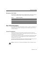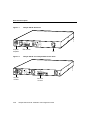
1
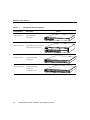
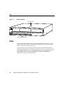
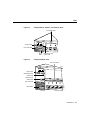
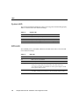
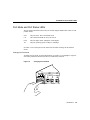
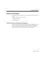
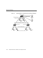
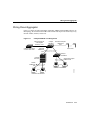
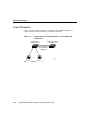
C H A PT E R
1
Introduction
The Catalyst 2900 series XL switches are workgroup Ethernet switches that supply
autosensing 10BaseT or 100BaseT connections on all ports. These switches–also referred
to as Catalyst 2900 switches–can be deployed as backbone switches aggregating 100BaseT
traffic from other switches and hubs or in mixed configurations connecting hubs, switches,
servers, and desktops.
This chapter is a functional overview of the Catalyst 2900 series. The following topics
briefly describe the components and features that are shared by all switches in the series:
•
•
•
•
Summary of key features
Physical components on the front and rear panels of each switch
Software and management options for the switches
Examples of Catalyst 2900 series switches in different network topologies
Summary of Key Features
The Catalyst 2900 switches are members of an extended network system of stackable,
modular LAN and WAN products that increase LAN performance, connect remote offices
and users, and provide secure access.
Figure 1-1 shows the four available versions of the Catalyst 2900 series XL switches, and
Table 1-1 lists their key features.
Introduction 1-1
Summary of Key Features
Figure 1-1
Catalyst 2900 Series XL Switches
Model Number
Description
Catalyst 2908 XL
8 fixed autosensing
10/100 ports
Switch
SERIES
RPS
1x
2x
3x
4x
5x
6x
7x
8x
MODE
Catalyst 2916M XL
16 fixed autosensing 10/100 ports
2 high-speed expansion slots
SERIES
1x
2x
3x
4x
5x
6x
7x
8x
9x
10x
11x
10x
11x
12x
13x
14x
15x
16x
14x
15x
16x
MODE
24 fixed autosensing
10/100 ports
10BaseT/100BaseTX
RPS
1x
2x
3x
4x
5x
6x
7x
8x
9x
12x
13x
SERIES
17x
18x
19x
20x
21x
22x
18x
19x
20x
21x
22x
MODE
Catalyst 2924C XL
22 fixed autosensing
10/100 ports
2 100BaseFX ports
24x
10BaseT/100BaseTX
RPS
1x
2x
3x
4x
5x
6x
7x
8x
MODE
1-2
23x
Catalyst 2900 Series XL Installation and Configuration Guide
SERIES
100BaseFX
9x
10x
11x
12x
13x
14x
15x
16x
17x
23x
24x
H11752
Catalyst 2924 XL
Summary of Key Features
Table 1-1
Summary of Key Features
Feature
Description
Performance and Configuration
• Autosensing transmission on 10/100 ports
• Autonegotiation of half- and full-duplex operation on 10/100 ports
• Full-duplex operation on 100BaseFX ports
• Two high-speed expansion slots supporting 10BaseT/100BaseTX,
100BaseFX and future gigabit, asynchronous transfer mode (ATM) and
Inter-Switch Link (ISL) modules (Catalyst 2916M XL only)
• Fast EtherChannel support for connections of up to 800 Mbps between
switches and servers
• Support for 2048 MAC addresses
• IEEE 802.1d Spanning-Tree Protocol support
• 4 Mb shared-memory architecture
• Cisco Group Management Protocol (CGMP) to limit the flooding of
multicast traffic to predefined ports
• Port security to prevent unauthorized access to the network
• Broadcast storm control to prevent performance degradation from broadcast
storms
• Embedded RMON (four groups)
Management
• Embedded World Wide Web interface for most management tasks
• Cisco IOS command-line interface (CLI) via the console port or Telnet
• CiscoView device-management application
Redundancy
• Connection for optional Cisco 600W AC redundant power system (RPS) as a
backup
Introduction 1-3
Front Panel Description
Front Panel Description
This section describes the switch 10/100 and 100BaseFX ports, expansion slots and their
associated modules, and the LEDs. All Ethernet ports and all LEDs are on the switch front
panel.
10/100 Ports
Catalyst 2900 10/100 ports are internally switched to all other switch ports and use RJ-45
connectors and Category 5 cabling. They can operate at either 10 Mbps or 100 Mbps in full
or half duplex. For autonegotiation with other devices, the ports are
IEEE 802.3u-compliant.
When connected to another device, a port senses the speed and duplex settings of the
attached device and advertises its own capabilities. If the connected device also supports
autonegotiation, the Catalyst 2900 port negotiates the best connection it can and configures
itself accordingly. Ports can also be explicitly set to operate in any combination of half
duplex, full duplex, 10 Mbps, or 100 Mbps. In all cases, the attached device must be within
100 meters of the switch.
100BaseFX Ports
The Catalyst 2924C XL switch (see Figure 1-2) has two 100BaseFX ports on the front
panel. These ports use 10/125- or 62.5/125-micron multimode fiber-optic cabling. In the
default full-duplex mode, these ports can connect to other 100BaseFX devices over
distances of up to 2 kilometers. In half-duplex mode, the ports support connections to
devices up to 412 meters from the switch.
100BaseFX ports default to full-duplex operation and do not autonegotiate.
1-4
Catalyst 2900 Series XL Installation and Configuration Guide
High-Speed Expansion Slots
Catalyst 2924C XL 100BaseFX Ports
10BaseT/100BaseTX
RPS
1x
2x
3x
4x
5x
6x
7x
8x
SERIES
100BaseFX
9x
10x
11x
12x
13x
14x
15x
MODE
10/100 ports
16x
17x
18x
19x
20x
21x
22x
23
H11771
Figure 1-2
24
100BaseFX ports
High-Speed Expansion Slots
The Catalyst 2916M XL switch (see Figure 1-3) has two high-speed expansion slots for the
Catalyst 2916M XL hot-swappable modules. These modules provide a variety of
possibilities for connecting backbones, servers, and other high-performance devices. Each
module port is internally switched to all other Catalyst 2916M XL ports.
The Catalyst 2916M XL modules automatically configure themselves when you insert
them in an expansion slot and tighten the thumb screws. The switch does not need to be
reset, and a power-on self-test (POST) verifies that the module is working properly before
it starts forwarding packets.
Introduction 1-5
LEDs
Figure 1-3
Catalyst 2916M XL
Expansion slots
H10928
SERIES
1x
2x
3x
4x
5x
6x
7x
8x
9x
10x
11x
12x
13x
14x
15x
16x
MODE
Autosensing 10/100 ports
LEDs
Catalyst 2900 LEDs are indicators of switch activity and performance. Figure 1-4 and
Figure 1-5 show the location of the LEDs and the Mode button. You can use the Mode
button to select one of the port mode LEDs.
The switch LEDs are also displayed on the image of the switch available through the
web-based Switch Manager. All of the LEDs described in this section, with the exception
of the utilization meter (UTL), are visible on the Basic System Configuration page of
Switch Manager. See the “Using Switch Manager” section in the “Web-Based
Management” chapter for more information.
1-6
Catalyst 2900 Series XL Installation and Configuration Guide
LEDs
Figure 1-4
Catalyst 2908 XL, 2924 XL, and 2924C XL LEDs
Port status LEDs
System LED
RPS
1x
2x
3x
H10330
Port mode LED
MODE
Mode
button
Figure 1-5
Redundant power
system LED
Catalyst 2916M XL LEDs
Port status LEDs
System LED
Redundant power
system LED
Expansion slot
status LEDs
Port mode LED
Mode button
MODE
2x
3x
4x
H10988
1x
Introduction 1-7
LEDs
System LED
The system LED indicates whether the system is receiving power and functioning properly.
Table 1-2 lists the LED colors and their meanings.
Table 1-2
System LED
Color
System Status
Off
System is not powered up.
Green
System is operating normally.
Amber
System is receiving power but is not functioning properly.
RPS LED
The redundant power system (RPS) LED shows the RPS status. Table 1-3 lists the LED
colors and their meanings.
Table 1-3
1-8
RPS LED
Color
RPS Status
Off
RPS is off or is not installed.
Green
RPS is operational.
Flashing green
The RPS and the switch AC power supply are both powered up. If the
switch power supply fails, the switch powers down and restarts after
15 seconds using power from the RPS. The switch goes through its normal
boot sequence when it restarts.
Amber
RPS is connected but not functioning properly. One of the power supplies
in the RPS could be powered down or a fan on the RPS could have failed.
Catalyst 2900 Series XL Installation and Configuration Guide
Port Mode and Port Status LEDs
Port Mode and Port Status LEDs
The port mode LED indicates the mode you selected using the Mode button. There are four
possible modes:
STAT
The port status. This is the default mode.
UTL
The current bandwidth in use by the switch.
FDUP
The port duplex mode: full duplex or half duplex.
100
The port operating speed: 10 Mbps or 100 Mbps.
See Table 1-4 for a description of the LED colors and their meanings for the different
modes.
Changing the Port Mode
To change the port mode, press the Mode button (see Figure 1-6) to highlight in sequence
each of the possibilities. Release the button to enable the lit function.
Changing the Port Mode
RPS
MODE
1x
2x
3x
H10326
Figure 1-6
Introduction 1-9
LEDs
Table 1-4
Port Status LEDs by Mode
Port Mode
Color
Meaning
STAT (port status)
Off
No link.
Solid green
Link present.
Flashing green
Activity; port is transmitting or receiving data.
Alternating
green-amber
Link fault. Error frames can affect connectivity, and errors such as excessive
collisions, CRC errors, and alignment and jabber errors are monitored for a
link-fault indication.
Solid amber
Port is not forwarding. Port was disabled by management or an address
violation or blocked by Spanning-Tree Protocol.
Green
If all port status LEDs are green, the switch is using 50% or more of its total
bandwidth capacity.
UTL (utilization)
If the right-most LED is off, the switch is using less than 50% of its total
bandwidth. If the LED to the left of the right-most LED is off, the switch is
using less than 25% of its total capacity. If the next LED to the left is off, the
switch is using 12.5% of its total bandwidth.
Each subsequent LED to the left that is turned off indicates a further reduction
of 50% in the amount of switch bandwidth in use.
FDUP (full duplex)
100 (speed)
1-10
Off
Port is operating in half duplex.
Green
Port is operating in full duplex.
Off
Port is operating at 10 Mbps.
Green
Port is operating at 100 Mbps.
Catalyst 2900 Series XL Installation and Configuration Guide
Expansion Slot LEDs
Expansion Slot LEDs
The expansion slot LEDs indicate the status of installed modules. The LEDs are numbered
1 (left slot) and 2 (right slot). Table 1-5 lists the LED colors and their meanings.
Table 1-5
Expansion Slot LEDs
Color
Expansion Slot Status
Off
No module is installed.
Green
Module is operating normally.
Amber
Module failed power-on self-test and should be replaced.
Rear Panel Description
The rear panels of the Catalyst 2900 switches (see Figure 1-7, Figure 1-8, and Figure 1-9)
contain an AC power receptacle, a redundant power system (RPS) receptacle, an RJ-45
console port, and fans.
Power Receptacles
You can provide power to the switch either by using the internal power supply or by
connecting the Cisco RPS to the RPS receptacle on the switch. Only one power source can
be supplying power to the switch at a time.
If you want to use the internal power supply, an autoranging unit supporting input voltages
between 100 and 240 VAC, use the supplied AC power cord to connect the AC power
receptacle to an AC power outlet.
If you want to use the RPS, the switch AC power cord must not be plugged in. See the Cisco
RPS documentation for detailed information on connecting to the RPS.
Warning Attach only the Cisco RPS (model PWR600-AC-RPS) to the RPS receptacle.
Introduction 1-11
Rear Panel Description
Catalyst 2908 XL Rear Panel
DC INPUT
CONSOLE
H10345
Figure 1-7
RATING
100-120/200-240V ~
0.7A/0.4A 50-60HZ
DC INPUTS FOR REMOTE
POWER SUPPLY
SPECIFIED IN MANUAL.
+5V @8A, +12V @0.5A
Figure 1-8
RPS connector
Fan
Catalyst 2924 XL and Catalyst 2924C XL Rear Panel
H11751
AC power
receptacle
RATING
100-127/200-240V~
1.0A/O.5A 50-80HZ
DC INPUTS FOR REMOTE
POWER SUPPLY
SPECIFIED IN MANUAL
+5V
@9A, +12V
@0.5A
AC power
connector
1-12
Cisco RPS
connector
Catalyst 2900 Series XL Installation and Configuration Guide
Console Port
Figure 1-9
Catalyst 2916M XL Rear Panel
RATING
100-120/200-240V ~
2.0A/1.0A 50-60HZ
DC INPUTS FOR REMOTE
POWER SUPPLY
SPECIFIED IN MANUAL.
+5V @24A, +12V @1.0A
H10929
Fans
DC INPUT
CONSOLE
RJ-45 console port
Redundant
power system
connector
AC power
connector
Console Port
You can connect a Catalyst 2900 to a PC or terminal via the console port and the supplied
rollover cable. For the data characteristics of the console port, see the “Connecting a
Terminal or PC to the Console Port” section in the “Installation” chapter.
Introduction 1-13
Catalyst 2900 Series XL Management Options
Catalyst 2900 Series XL Management Options
You can use the following techniques to manage Catalyst 2900 series switches:
•
Catalyst 2900 series Switch Manager
With JavaScript enabled on either Netscape Communicator 4.0 or Microsoft Internet
Explorer 4.0, you can use the web-based Switch Manager to configure the switch,
monitor a live image of the switch, and display statistics. If you are connected to the
Internet, you can link directly from the switch home page to Cisco Systems for new
software releases and the latest Catalyst 2900 series documentation.
•
Cisco IOS command-line interface (CLI) via console or Telnet
You can access the Cisco IOS CLI by connecting a PC or terminal to the console port
on the rear panel or by using Telnet. Instructions for using the CLI are in the “Cisco IOS
Management” chapter.
•
CiscoView
The CiscoView device-management application displays an image of the switch. You
can point and click on the image to set configuration parameters and get statistics about
the switch and its performance. CiscoView runs as a stand-alone application or as part
of an SNMP network-management platform.
•
SNMP network management platforms
Catalyst 2900 series switches can be managed with an SNMP-compatible management
station running such platforms as HP OpenView and SunNet Manager. The switch
supports a comprehensive set of MIB extensions along with MIB II, the 802.1d bridge
MIB, and four Remote Monitoring (RMON) groups.
1-14
Catalyst 2900 Series XL Installation and Configuration Guide
Deployment Strategies
Deployment Strategies
This section describes three examples of how you could deploy the Catalyst 2900 in your
network.
•
•
•
High-performance client/server workgroup
Wiring closet aggregator
Power workgroup
High-Performance Client/Server Workgroup
Figure 1-10 shows a Catalyst 2916M XL connecting workstations, 100BaseTX hubs, and
servers in a topology suited to client/server applications. The links to the 100BaseTX
servers and workstations can be full duplex. A repeater does not support full-duplex
transmission, so the links to the 100BaseTX repeaters are always half duplex.
Introduction 1-15
Deployment Strategies
Figure 1-10
Catalyst 2916M XL in a High-Performance Client/Server Workgroup
Catalyst 2924M XL
Switched full-duplex
100BaseTX links
Switched half-duplex
100BaseTX links
100BaseTX
servers
Single workstations
Switched half-duplex 100BaseTX links
FastHub 300
FastHub 300
100BaseTX hub-attached workstations
1-16
Catalyst 2900 Series XL Installation and Configuration Guide
NM5332
Shared 100BaseTX links
Wiring Closet Aggregator
Wiring Closet Aggregator
Figure 1-11 shows a Catalyst 2916M XL connecting 100BaseTX and 10BaseT devices. In
this topology, the switch is in the middle of the network and can provide connectivity to any
mixture of hubs, switches, and servers.
Figure 1-11
Catalyst 2916M XL in a Wiring Closet
Fast EtherChannel,
ATM, Gigabit
Ethernet, or ISL
Catalyst 5000 switch
or Cisco 7000 router
Catalyst
2924M XL
Switched full-duplex
100BaseTX
links
Server farm
Switched
100BaseTX
links
Catalyst
1900/2820
FastHub
300 stack
Switched full-duplex
10BaseT links
Shared
100BaseTX
links
100BaseTX workstations
NM5334
10BaseT workstations
Introduction 1-17
Deployment Strategies
Power Workgroup
Figure 1-12 shows a Catalyst 2924C XL or 2924 XL with a 100BaseFX uplink to a
Catalyst 5000 and 10/100 connections to individual workstations.
Figure 1-12
Catalyst 2924C XL or Catalyst 2924 XL in a Power Workgroup
Configuration
Catalyst 2924 or
Catalyst 2924C XL
Catalyst 5000 switch or
Cisco 7000 router
10BaseT and 100BaseTX workstations
1-18
Catalyst 2900 Series XL Installation and Configuration Guide
H11765
Fast EtherChannel
over 100BaseTX or
100BaseFX