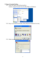
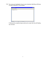
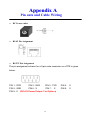
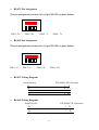
1
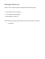
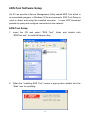
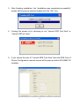
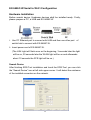
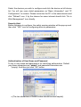
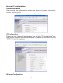
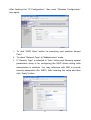
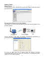
DDS SERIAL TO WiFi CONVERTER EX-9486C-W User Manual Table of Contents Introduction …………………………………………………………………… 3 Overview …………………………………………………………………………. 4 Package Check List …………………………………………………………….. 5 Product Features ……………………………………………………………….. 6 Hardware Specifications ………………………………………………………. 8 Converter Description …………………………………………………….. 11 Product Panel Views …………………………………………………….……. 11 Left Side …………………………………………………………………………. 12 Right side ………………………………………………………………………… 14 LED Indicators ………………………………………………………………….. 15 Wiring Architecture ……………………………………………………………. 16 RS-232 ……………………………………………………………………………. 16 RS-422/RS-485 ………………………………………………………………….. 16 Serial to Wi-Fi Converter Configuration ………………...………... 17 Software Setup and Initial IP Configuration ……………………….………. 16 EDS Tool Software Setup ……………………………………………………… 18 EDS Tool Setup ………………………………………………………………… 18 Serial to Wi-Fi Configuration …………………………………………. 20 Hardware Installation ………………………………………………………….. 20 Search Device …………………………………………………………………... 20 Security Alert ……………………………………………………………………. 20 Authentication …………………………………………………………………. 21 Device IP Configuration ……………………………………………………… 22 System Information ……………………………………………………………… 22 IP Configuration ………………………………………………………………... 22 1 Wireless Configuration …………………………………………………………. 23 System Tools …………………………………………………………………… 24 Restart Tools ……………………………………………………………………. 24 Network Line Disconnection ………………………………………………..….. 24 Test Step with Wired and Wireless…………………………………………… 26 Enter to Web Management …………………………………………………........ 26 Serial Protocol Setting ………………………………………………………….... 26 Service Mode Setting ………………………………………………………......... 29 Hyper Terminal Setting ………………………………………………………..... 30 Appendix A - Pin Outs and Cable Wiring …………………… 34 DC Power Outlet ……………………………………………………………….. 34 RJ-45 Pin Assignment ……………………………………………………… 34 RS-232 Pin Assignment ……………………………………………………… 34 RS-422 Pin Assignment ………………………………… ………………… 35 RS-485 Pin Assignment ……………………………………….……...………. 35 2 Introduction Serial to Wi-Fi converter is provided new ways of connecting serial devices to a Wireless LAN (Wi-Fi 802.11 b/g ). Serial to Wi-Fi Converter is designed to operate serial ports through wireless (Wi-Fi 802.11 b/g) or entity line (RJ-45 cable) over 10/100Mbps Ethernet networks. The data is transmitted via TCP/IP protocol. Therefore control is available via Ethernet, Intranet and Internet. Serial to Wi-Fi Converter is packaged in a case well suited for industrial environments. All serial ports operate in common RS-232 mode, industrial RS-422 and RS-485 modes configuration. With the maturity of Wi-Fi technology of 802.11b/g, delivering cost effective becomes increasingly important. Model EX-9486C-W of Serial to Wi-Fi converter product is a more competitive price by careful selecting high quality with competitive prices components in the world, the product design is adopted AR2317 single-chip, made network connectivity possible with affordable cost for virtually all kinds of devices. This user manual will guide you step by step for setting the various functions of model EX-9486C-W product. For questions contact [email protected] The following topics are covered in this chapter: Overview Package Checklist Product Features Product Specifications 3 Ove r vie w Serial to Wi-Fi Converter is provided a perfect solution to make your industrial serial devices Internet ready instantly via wireless LAN. Model EX-9486C-W with Atheros/AR2317 chipset, Serial to Wi-Fi Converter makes them the ideal choice for connecting your RS-232 or RS-422/485 serial devices such as PLCs, meters, and sensors—to an IP-based Wi-Fi ∕ Ethernet LAN, making it possible for your software to access serial devices anywhere and anytime over a wireless local LAN or the Internet. For RS-232 pin assignment of Atheros Series, it just provides TxD, RxD and GND pins only without others like TXRTS, CTS, DTR, DSR and DCD. Serial to Wi-Fi Converter support manual configuration via the handy web browser console and many protocols including TCP, IP, UDP, HTTP, DHCP, ICMP, and ARP. They are the best solution to network your serial devices. 4 Pa ck a ge Che ck List Serial to Wi-Fi Converter product is shipped with the following items: □□ 1 unit of Serial to Wi-Fi Converter □□ 1 unit of dipole antenna(2.0dBi) □□ Documentation & Utility CD NOTE: Notify your sales representative if any of the above items is missing or damaged. 5 Produc t Fe at ure s Data Conversion between RS-232/422/485 and Wireless Lan Convert serial device (RS-232, RS-422, RS-485) data/signal into the TCP/IP package data/signal and send them out with the Ethernet DataStream via Wi-Fi wireless; or convert the TCP/IP package data/signal into serial device data/signal. Wi-Fi Wireless LAN(802.11 b/g) It based on the latest industry standard Wi-Fi Certified IEEE 802.11b / g specification; it offers maximum channel speeds of up to 54 Mbps. The Wi-Fi function maintains interoperability within the 2. ~ 2.5 GHz frequency band, offering full compatibility with 802.11b / g networks. This integrated wireless solution of Serial to Ethernet Converter is widely deployed in business environments and is the standard for wireless access in public places. It also supports key security features like Wi-Fi Protected Access (WPA), WEP and 802.1x. Dynamic IP Configuration Support DHCP client mode, simplifying network address configuration and management. Dual LAN Speed Support 10/100 Mbps Ethernet, auto-detected. 6 Server / Client Dual Modes Series can be configured as network server or network client. In the client mode, it can be installed in network which is protected by NAT router or firewall, without the need of a real IP address. Web-based Setup Parameters setup is based on HTTPS protocol by using standard browsers (IE and Netscape). No special software would be required. To use https to enter Web-Server of converter (For example https:∕∕ . . . ) Built-in Security Control It is protected by both setup password and access password to prevent intruders. Remote updated Firmware can be reprogrammed directly via Ethernet network to keep up with latest network standards. 7 Hardware Specifications WLAN 1. Standard Compliance : IEEE 802.11 b / g 2. Spread Spectrum Technology: DSSS, OFDM 3. Tx Power 11b: Maximum 20 dBm 4. Tx Power 11g: Maximum 18 dBm 5. Rx Sensitivity: -70 dBm @ 54 Mbps, -85 dBm @ 11Mbps 6. Transmission Rate: 54 Mbps (max.) with auto fallback (54,48, 36, 24, 18, 12, 11, 9, 6, 5.5, 2, 1 Mbps) 7. Transmission distance: Up to 100 meters (@12 Mbps, in open areas) 8. Security: WEP 64-bit/128-bit data encryption, AES, WPA2 9. Antenna Connector: Reverse SMA, 2 dbi Antenna 10. Network Mode: Infrastructure, Ad-Hoc LAN (For configuration / Ethernet hub) 1. Ethernet: 10/100 Mbps, RJ45 2. Protection: Built-in 1.5 KV magnetic isolation Serial Communication Parameters 1. No. of ports : 1 * RS-232/422/485 port, male DB9, S/W selectable 2. RS-232 Signals : TxD, RxD and GND only 3. RS-422 Signal : Tx+ , Tx- , Rx+ , Rx – 4. RS-485 Signal : Data+ , Data5. Serial Line Protection : 15 KV ESD for all signals 8 Serial Communication Parameters 1. Parity: None, Even, Odd, Space, Mark 2. Data bits: 5, 6, 7, 8 3. Stop bits: 1, 1.5, 2 4. Flow control: XON/XOFF 5. Speed: 110 bps to 115.2+ Kbps Power Requirements 1. Power input 1: 12 VDC & 1 A Environmental 1. Operating Temperature : 0 to 70°C , 5 to 95% RH 2. Storage Temperature : -20 to 85°C (-4 to 185°F), 5 to 95%RH 3. Regulatory Approvals RoHS FCC, CE Software Features 1. Protocols : ICMP, IP, TCP, UDP, DHCP, BootP, ARP / RARP, Telnet, RTelnet, DNS, SNMP MIB II, HTTP, SMTP, SNTP 2. Serial mode : Virtual Com / TCP Server / TCP Client / UDP / Pairing TCP Alive Check Timeout Inactivity Timeout Delimiter for Data Packing Force TX Timeout for Data Packing 9 Max 5 Hosts simultaneous connection : Virtual Com / TCP server 1. Security: HTTPS, SSH v2 2. Event notification : By email / SNMP trap / Syslog SNMP Trap Cold/Warm Start DSR, DCD Changed IP Changed Authentication Fail 3. Utilities : Windows NT/2000/XP/2003/VISTA Device discovery Auto IP report Device setting (run-time change, no rebooting) Access control list Group setting Device monitoring Serial port monitoring Log info Virtual COM/TTY Drivers (WDM mode, configuration in windows device manager) : Windows NT/2000/XP/2003, VISTA 10 Converter Description Product Panel Views Power Outlet DC-In Serial Port RS-485/RS-422 LAN RJ-45 Serial Port RS-232 Antenna Reset Button LED Indicators 11 Left Side DC-In Power Outlet The Serial to Wi-Fi Converter is powered by a single 12V DC(Inner positive/outer negative) power supply and 1.0 A of current. A suitable power supply adapter is part of the packaging. Connect the power line to the power outlet at the left side of Serial to Wi-Fi Converter and put the adapter into the socket. If the power is properly supplied, the “SYS” red color LED will be on after 30 seconds. DC-In Power Outlet Ethernet Port Antenna Reset Button Ethernet Port The connector for network is the usual RJ45. Simply connect it to your network switch or Hub. When the connection is made, the LAN LED indicator will light. When data traffic occurs on the network, red (Rx/Tx) indicator will blink during data transferring and receiving. Antenna Connector The connector for antenna is a standard reverse SMA jack. Simply connect it to a 2.0dBi or 5.0dBi dipole antenna (Standard Rubber Duck) and it is 50 Ohms impedance and can support 2.4GHz frequency. 12 Reset Button If by any chance, you forget the setup password, or have incorrect settings making EX-9486C-W converter inoperable. First, use any point tip to push this button and hold it about 5 seconds. the factory default 13 All the parameters will be reset to Right Side RS-422/RS-485 RS-232 Serial I/O Port of RS-232/RS-422/RS-485 Connect the serial data cable between the Wi-Fi converter and the serial device. Follow the parameter setup procedures to configure the converter (see the following chapters ). 14 LED Indicators SYS (Red): Power indicator (When the power is on, the LED will be on.) LAN (Green): Network signal indicator (When the LAN signal is detected, the LED will be on.) WLAN (Red): Wireless Lan indicator (When wireless LAN signal is connected, the LED will be on ) TX / RX (Yellow): Data sent indicator (When data are sent out to the network, the LED will be blink.) Data received indicator (When data are received from the network, the LED will be blink.) 15 Wiring Architecture RS-232 Wiring Architecture RS-422/RS-485 Wiring Architecture When you finish the steps mentioned above and the LED indicators are as shown, the converter is installed correctly. You can use the Utility Setup CD to setup the IP Address. To proceed the advanced parameter setup, please use a web browser (IE or Netscape) to continue the detailed settings. 16 Serial to Wi-Fi Converter Configuration Software Setup and Initial IP Configuration When setting up your converter for the first time, the first thing you should do is configure the IP address. This chapter introduces the method how to install the program and how to configure the serial to Wi-Fi Converter device’s IP address. For quick and easy start , We suggest you to reference “Quick Installation Guide” manual. The following topics are covered in this chapter: EDS Tool Software Setup Serial to Wi-Fi Converter Configuration Converter Configuration through Web 17 EDS-Tool Software Setup On PC we provide a Device Management Utility named EDS Tool which is an executable program in Windows 32 bit environments. EDS Tool Setup is used to detect and setup the installed converter. It uses UDP broadcast packets to query and configure converters on the network. EDS-Tool Setup 1. Insert the CD and select “EDS Tool”, folder and double click “EDSTool.exe”, to install Windows utility. 2. When the “installing EDS Tool” screen is pop-up then double click the “Start” icon for installing. 18 3. After finishing installation, the “installation was completed successfully” screen will be pop-up and just double click the “OK” icon. 4. Coming the screen is for choosing to run “Launch EDS Tool Now” or “Launch DSTool Later”. 5. If you choice the item of “Launch EDS-Tool Now” then the EDS-Tool of Device Configuration manual screen will be pop-up before EX-9486C-W installed. 19 EX-9486C-W Serial to Wi-Fi Configuration Hardware Installation Before search device, Hardware devices shall be installed ready. Firstly, please prepare a PC, a HUB and EX-9486C-W. 1. Use PC Ethernet port to connect with HUB and then use other port of switch hub to connect with EX-9486C-W. 2. Insert power cord of EX-9486C-W. (The LAN Light will flash once on the beginning, 3 seconds later the light will be on, 30 seconds later the WLAN light will be on and afterwards about 10 seconds the SYS light will be on.) Search Device After finishing EDS-Tool installation and lunch the EDS-Tool, you can click the “Search Device” icon at left side upper corner. It will detect the existence of the installed converters on the network. 20 Select the devices you wish to configure and click the device on left device list. You will see more detail parameters as “Basic Information” and “IP Configuration” on screen. Please correction the PC to the same domain and click “Refresh” icon, if by the chance for same intranet should click “Go to Web Management” icon directly Security Alert Before entrance to configure, the safety warning window will be pop-up and then click “YES” icon for configuring device’s parameters. Authentication of User Name and Password To key in user name and password is for identifying authorization. Default user name characters are “admin” and password characters are “ “(empty). And then just click “OK” button. *(The two characters of Default value should be small capital). 21 Device IP Configuration System Information After entering the authorization window and then the “System Information” window will be pop-up. IP Configuration Please get into “Network Configuration” icon of item “IP Configuration” first, and correct complete relevant parameters to wireless IP and then click the “APPLY” button for applying. Wireless Configuration 22 After finishing the “IP Configuration”, then enter “Wireless Configuration” item again. 1. To click “SSID Scan” button for searching your wireless Access Point. 2. To select “Network Type” at “Infrastructure” mode. 3. If “Security Type” is selected in “Auto” status and following several parameters setup is for configuring the WEP status during data transmission in wireless. You may reference with MIS to provide security parameters (Ex: WEP). After finishing the setup and then click “Apply” button. 23 System Tools Restart Device Click the System Tools – Restart Device and click “Reboot” button for refresh new parameters. Disconnection Network Line to be wireless After Reboot, you should remove Network connection line and change to the Wireless statues. Please attention if the setup of wireless Configuration parameters is corrected then EDS-Tool can pass over the IP. If it can not pass over the IP, please check the setup of wireless Configuration parameters to confirm the information is mistake and please inquire with MIS superintendent. 24 Test steps with wired and wireless of Convey or receive. Enter to web management 1 Enter to web setting window of “System Information”. 2 Just go over previous procedure again to “Device IP Configuration” setup window. Serial Communication Protocol setting 3 Click “Port Serial Setting” button of parameters setting list on left side of the window. 4 There are three setting items under “Port Serial Setting” and then you just click “Serial Configuration’ button to show the serial protocol parameters. You can setup the parameters as for the testing request. 25 5 Choose the “Interface” of serial port as you need. 6 Setting the “Baud Rate” of serial port transit 7 Setting the “Data Bits” of serial port transit 26 8 Setting the “Stop Bits” of serial port transit 9 Setting the “Parity” check of serial port transit 10 Setting the “Flow Control” of serial port transit 27 Service Mode setting 11 Setting the “Service Mode” of serial port transit 11.1 Firstly, please chose the “TCP Service Mode” in service mode selecting bar. 11.2 Setting the “TCP Service Port” and port number is depend on your requirement. (Exp. Open socket port as 100) 28 12 Hyper Terminal Setting 12.1 Open the Hyper terminating machine. Initiate a Hyper Terminal from the Start Menu in Windows 12.2 Key in a terminal name (Exp. Test) and press OK button for entry 12.3 Select communication as in “TCP/IP’ mode 29 12.4 Key in the converter IP and socket port number Enter the converter’s IP address (e.g. 192.168.0.115) at the “Host address:” field, and the Socket port number set for the Serial Port 1 at the “Port number:” field (e.g 100). (The Socket type of the Serial Port 1 should be “TCP Server”.) Press “OK” button. 12.5 After completing the parameters setting and then the hyper terminal window will be pop up. If the Hyper Terminal connects with the converter successfully, the time clock at the “left lower” corner in window “Connected hh:mm:ss” will start counting. 30 12.6 You may use keyboard to key in any characters that they will show as reply characters in the window. Following the complete steps as above to mean that the self testing are success. 31 Appendix A Pin outs and Cable Wiring □□ DC Power outlet □□ RJ-45 Pin Assignment □□ RS-232 Pin Assignment The pin assignment scheme for a 9-pin male connector on a DTE is given below. PIN 1 : DCD PIN 2 : RXD PIN 3 : TXD PIN 5 : GND PIN 6 : X PIN 7 : X PIN 9 : X DC+5V Power Output- For Option 32 PIN 4 : X PIN 8 : X □□ RS-422 Pin Assignment The pin assignment scheme for a 4-pin RS-422 is given below. 1 PIN 1 : R- 2 3 4 PIN 2 : R+ PIN 3 : T- PIN 4 : T+ □□ RS-485 Pin Assignment The pin assignment scheme for a 4-pin RS-485 is given below. 1 PIN 1 : X 2 3 4 PIN 2 : X PIN 3 : D- PIN 4 : D+ □□ RS-422 Wiring Diagram Serial Device RR+ TT+ EX-9486C-W Converter 3 T4 T+ 1 R2 R+ □□ RS-485 Wiring Diagram Serial Device EX-9486C-W Converter D- 1 D- D+ 2 D+ 33