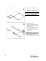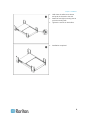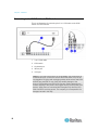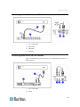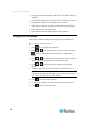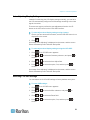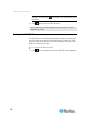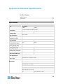
1
LCD KVM Console (T1700/T1900) User Guide Release 1.1 Copyright © 2012 Raritan, Inc. T1700_T1900-0H-v1.1-E July 2012 255-37-0114-00 This document contains proprietary information that is protected by copyright. All rights reserved. No part of this document may be photocopied, reproduced, or translated into another language without express prior written consent of Raritan, Inc. © Copyright 2012 Raritan, Inc. All third-party software and hardware mentioned in this document are registered trademarks or trademarks of and are the property of their respective holders. FCC Information This equipment has been tested and found to comply with the limits for a Class A digital device, pursuant to Part 15 of the FCC Rules. These limits are designed to provide reasonable protection against harmful interference in a commercial installation. This equipment generates, uses, and can radiate radio frequency energy and if not installed and used in accordance with the instructions, may cause harmful interference to radio communications. Operation of this equipment in a residential environment may cause harmful interference. VCCI Information (Japan) Raritan is not responsible for damage to this product resulting from accident, disaster, misuse, abuse, non-Raritan modification of the product, or other events outside of Raritan's reasonable control or not arising under normal operating conditions. Contents Important Safeguards v What the Warranty Does Not Cover .............................................................................................. v Safety Instructions ........................................................................................................................ vi Chapter 1 Introduction 1 Package Content ........................................................................................................................... 1 T1700................................................................................................................................... 1 T1900................................................................................................................................... 1 Structure Diagram.......................................................................................................................... 2 Chapter 2 Installation 3 Before Installation .......................................................................................................................... 3 Rack-Mounting the LCD KVM Console ......................................................................................... 3 1. Installing the Rear L-bracket............................................................................................ 4 2. Aligning the Rear L-brackets ........................................................................................... 4 3. Fixing the LCD KVM Console into the Rack.................................................................... 5 How to Install "One Man" Installation Slides.................................................................................. 6 Installing into Rack .............................................................................................................. 7 Connecting to the KVM Switch via PS/2 Interface....................................................................... 10 Connecting to the KVM Switch via USB Interface ....................................................................... 11 Connecting to the Server via PS/2 Interface ............................................................................... 11 Connecting to the Server via USB Interface................................................................................ 12 Chapter 3 Operation 13 How to Use the LCD KVM Console ............................................................................................. 13 Touchpad Buttons ............................................................................................................. 14 How to Use the Slides.................................................................................................................. 15 Chapter 4 LCD Panel Operation 16 LCD Membrane............................................................................................................................ 16 LCD OSD Layout ......................................................................................................................... 17 OSD Submenus ........................................................................................................................... 18 Image................................................................................................................................. 18 iii Contents Geometry ........................................................................................................................... 19 Misc ................................................................................................................................... 19 Changing LCD OSD Settings ......................................................................................................20 Auto-Adjusting Display Settings................................................................................................... 21 Resetting LCD OSD Settings....................................................................................................... 21 Quitting the LCD OSD Menu ....................................................................................................... 22 Appendix A Standard Specifications 23 Specifications............................................................................................................................... 23 Dimension .................................................................................................................................... 24 Appendix B Ground Screw 25 Appendix C Troubleshooting 26 Index 27 iv Important Safeguards Read all these instructions carefully before you use the device. Save this manual for future reference. What the Warranty Does Not Cover Any product, on which the serial number has been defaced, modified or removed. Damage, deterioration or malfunction resulting from: Accident, misuse, neglect, fire, water, lightning, or other acts of nature, unauthorized product modification, or failure to follow instructions supplied with the product. Repair or attempted repair by anyone not authorized by us. Any damage of the product due to shipment. Removal or installation of the product. Causes external to the product, such as electric power fluctuation or failure. Use of supplies or parts not meeting our specifications. Normal wear and tear. Any other causes which does not relate to a product defect. Removal, installation, and set-up service charges. v Important Safeguards Safety Instructions vi Unplug equipment before cleaning. Don't use liquid or spray detergent; use a moist cloth. Keep equipment away from excessive humidity and heat. Preferably, keep it in an air-conditioned environment with temperatures not exceeding 40º Celsius (104º Fahrenheit). When installing, place the equipment on a sturdy, level surface to prevent it from accidentally falling and causing damage to other equipment or injury to persons nearby. When the drawer is in an open position, do not cover, block or in any way obstruct the gap between it and the power supply. Proper air convection is necessary to keep it from overheating. Arrange the equipment's power cord in such a way that others won't trip or fall over it. If you are using a power cord that didn't ship with the equipment, ensure that it is rated for the voltage and current labeled on the equipment's electrical ratings label. The voltage rating on the cord should be higher than the one listed on the equipment's ratings label. Observe all precautions and warnings attached to the equipment. If you don't intend on using the equipment for a long time, disconnect it from the power outlet to prevent being damaged by transient over-voltage. Keep all liquids away from the equipment to minimize the risk of accidental spillage. Liquid spilled on to the power supply or on other hardware may cause damage, fire or electrical shock. Only qualified service personnel should open the chassis. Opening it yourself could irreparably damage the equipment and invalidate its warranty. If any part of the equipment becomes damaged or stops functioning, have it checked by qualified service personnel. Chapter 1 Introduction The User Guide introduces the Raritan LCD KVM Console, a 1U rackmount LCD KVM drawer for use with the KVM switch or server in the data center, server room or the like. There are two types of the product: T1700 and T1900. These models are identical in almost every aspect except that T1700 comes with a 17" LCD monitor and T1900 comes with a 19" one. In This Chapter Package Content .......................................................................................1 Structure Diagram .....................................................................................2 Package Content Raritan LCD KVM Console comes with the standard parts shown in this section. Check and make sure they are included and in good condition. If anything is missing, or damaged, contact the supplier immediately. T1700 1. LCD KVM drawer x 1 pc 2. Fasteners for rear L-bracket x 4 pcs 3. Rear mounting L-bracket x 1 pair *T1700 series mounting depth-adjustable from 395 to 880mm 4. 3-in-1 KVM cable x 1 pc 5. Power cord x 1 pc T1900 1. LCD KVM drawer x 1 pc 2. Single or “one man” installation slides x 1 package 3. 3-in-1 KVM cable x 1 pc 4. Power cord x 1 pc 1 Chapter 1: Introduction Structure Diagram 1. Carry handle to release the 2-pt lock 2. 2-point lock 3. LCD screen 4. LCD membrane 5. Adjustable rear mounting L-bracket 6. Micro switch for screen auto power off 7. Keyboard 8. Touchpad 2 Chapter 2 Installation In This Chapter Before Installation......................................................................................3 Rack-Mounting the LCD KVM Console .....................................................3 How to Install "One Man" Installation Slides .............................................6 Connecting to the KVM Switch via PS/2 Interface ..................................10 Connecting to the KVM Switch via USB Interface...................................11 Connecting to the Server via PS/2 Interface ...........................................11 Connecting to the Server via USB Interface............................................12 Before Installation It is very important to locate the LCD KVM Console in a suitable environment. The surface for placing and fixing the LCD KVM Console should be stable and level or mounted into a suitable cabinet. Make sure the place has good ventilation, is out of direct sunlight, away from sources of excessive dust, dirt, heat, water, moisture, and vibration. Convenience for connecting the LCD KVM Console to the related facilities should be well considered too. Rack-Mounting the LCD KVM Console There are three major steps to rack-mount the LCD KVM Console. 1. Install the rear L-bracket to the LCD KVM Console. 2. Align the rear L-brackets to a suitable length for the rack. 3. Fix the LCD KVM Console into the rack. 3 Chapter 2: Installation 1. Installing the Rear L-bracket a. Install each rear L-bracket using two fasteners shown in the diagram. b. Leave the fasteners slightly loose. 2. Aligning the Rear L-brackets a. Measure the front and rear mounting depth of the rack. b. Align each rear L-bracket to a suitable length and tighten the fasteners shown in the diagram. 4 Chapter 2: Installation 3. Fixing the LCD KVM Console into the Rack Fix the LCD KVM Console into the rack. Note: Hardware (screws and cage nuts) for fixing the mounting bracket into the rack is not provided. 5 Chapter 2: Installation How to Install "One Man" Installation Slides Component list 6 1 Mounting bracket x 2 pcs 2 Front mounting ear (left & right) x 2 pcs 3 Support bracket x 4 pcs 4 M6 cage nut x 6 pcs 5 M6 washer x 8 pcs Chapter 2: Installation Component list 6 M6*15mm screw x 8 pcs 7 M3.2*4.5mm screw x 14 pcs Note: Components 2, 3 and 7 have been pre-installed onto the T1900 LCD KVM Console and therefore are not in the component pack. Installing into Rack Attach the mounting bracket to vertical mounting rails. Adjust the rear mounting bracket to fit your rack. Repeat the above steps for the other side. Caution: Leave the screws slightly loose (not release). 7 Chapter 2: Installation Attach support brackets to chassis with M3.2*4.5mm screw x 3 pcs. Repeat the above step for the other side. Note: You can ignore step 2 because the support brackets have been pre-installed onto the T1900 LCD KVM Console. Pick up the chassis. Insert inner members of slides into the already mounted internal slide members in the rack. Push the white-arrow button on each slide that is installed on the LCD keyboard drawer to unlock (Push at the same time). Caution: Be careful when pushing the chassis into the left and right slides. Avoid pressing the red button located on either side of the slide. 8 Chapter 2: Installation Hold down the white-arrow button and push the chassis to the end. Attach left and right mounting ears to vertical mounting rails. Tighten the screws on both sides. Installation completed. 9 Chapter 2: Installation Connecting to the KVM Switch via PS/2 Interface This is an illustration of connecting the 3-in-1 KVM cable to the KVM switch via PS/2 Interface. 1. 3-in-1 KVM cable 2. KVM switch 3. Keyboard port 4. Mouse port 5. VGA port Caution: The LCD KVM Console is hot-pluggable, but components of connected devices, such as the servers and KVM switch, may not be hot-pluggable. Plugging and unplugging cables while servers and KVM switches are powered on may cause irreversible damage to the servers, KVM switches and LCD KVM Console. Before attempting to connect anything to the product, we suggest turning off the power to all devices. Apply power to connected devices again only after the LCD KVM Console is receiving power. The company is not responsible for damages caused in this way. 10 Chapter 2: Installation Connecting to the KVM Switch via USB Interface 1. 3-in-1 KVM cable 2. KVM switch 3. USB ports 4. VGA port Connecting to the Server via PS/2 Interface This is an illustration of connecting the 3-in-1 KVM cable to a server via PS/2 interface. 1. 3-in-1 KVM cable 2. Server 11 Chapter 2: Installation 3. Keyboard port 4. Mouse port 5. VGA port Connecting to the Server via USB Interface 1. 3-in-1 KVM cable 2. Server 3. USB port 4. VGA port 12 Chapter 3 Operation In This Chapter How to Use the LCD KVM Console.........................................................13 How to Use the Slides .............................................................................15 How to Use the LCD KVM Console 1. Gently pull the tab toward the front of the LCD. 2. Flip up the LCD to a suitable angle. 13 Chapter 3: Operation 3. Operate the LCD KVM Console. For information on LCD membrane buttons and onscreen menu, see Onscreen Display Operation (see "LCD Membrane" on page 16) and Onscreen Menu. Touchpad Buttons The buttons adjacent to the touchpad function the same as those on a two-button mouse. Number Function 14 1 The button is similar to the left button on a mouse, which is used for item selection or program activation. 2 The button is similar to the right button on a mouse, which can trigger a context menu. Chapter 3: Operation How to Use the Slides 1. Locate a black-arrow release button on the outside of each slide. 2. Push the black-arrow buttons at both sides before pushing the LCD KVM Console into place. 3. Keep pushing the black-arrow buttons until the LCD KVM Console is placed into the rack. 15 Chapter 4 LCD Panel Operation You can customize visual display properties of the built-in LCD display, such as colors and image position, by changing the settings on the LCD OSD menu. In This Chapter LCD Membrane .......................................................................................16 LCD OSD Layout.....................................................................................17 OSD Submenus.......................................................................................18 Changing LCD OSD Settings ..................................................................20 Auto-Adjusting Display Settings ..............................................................21 Resetting LCD OSD Settings ..................................................................21 Quitting the LCD OSD Menu ...................................................................22 LCD Membrane 1. LCD membrane 16 Chapter 4: LCD Panel Operation The buttons at the bottom of the LCD panel are used to control the LCD display and navigate through the LCD's OSD interface. Button Function Turn on/off the LCD display. Adjacent LED turns blue when turned on. Adjacent LED is not lit when turned off. Two functions: Activate the LCD's OSD interface. Confirm the current selection when an OSD menu or field is highlighted. Two functions: Move the highlight on the LCD OSD menu. functions as a shortcut button to auto-adjust visual display settings without activating the LCD's OSD interface. Adjust the value or switch among available options after any OSD field is selected. Exit from current LCD OSD menu or submenu. LCD OSD Layout You can view the LCD information, and adjust the visual images displayed and the LCD OSD properties through LCD OSD menus. 17 Chapter 4: LCD Panel Operation Number Information Description OSD title The bar shows the LCD version, and the resolution and refresh rate applied to current video image. Submenu section The left column shows the OSD submenus. Only three submenus are available: Image, Geometry, and Misc. Setting section The right column shows the fields available in the selected submenu. Help bar The bar shows the buttons that work with the LCD OSD menu. OSD Submenus Only three submenus are enabled for LCD KVM Console: Image, Geometry, and Misc. Image This submenu determines how the screen image is displayed. 18 Brightness: Adjust background black level of the screen image. Contrast: Adjust the difference between the image background (black level) and the foreground (white level). Color Temp: The screen color is not user-configurable -- always at 9300K. Red: Adjust the red color. Green: Adjust the green color. Blue: Adjust the blue color. Chapter 4: LCD Panel Operation Geometry The submenu controls geometry, clock and phase settings. Auto Adjust: Fine tune the video signal to eliminate waviness and distortion. The "Auto Adjusting" message is displayed during the process. H Position: Align the screen image left or right. V Position: Align the screen image up or down. Phase: Adjust the phase setting. Clock: Adjust the clock setting. Misc This submenu provides other OSD or screen settings, and the reset function. 19 Chapter 4: LCD Panel Operation Language: Select the language in which the LCD's OSD interface is displayed. OSD Position: Determine the position of the LCD OSD on the screen. Display Mode: Adjust the LCD display's video resolution. OSD Time: Set the time duration in seconds that the LCD OSD is visible after the last time any button of the LCD controls is pressed. Ratio: Adjust the screen image's ratio. Reset: Restore the LCD OSD settings to factory defaults. Changing LCD OSD Settings Follow this procedure to change the settings on the LCD OSD menu. To change the OSD settings: 1. Press . The LCD OSD menu appears. 2. Press or to select the submenu (icon) you want, and press to confirm. When a submenu is selected, it is highlighted in orange. or to select the field whose value or option you want to 3. Press change. When a field is selected, it is highlighted in blue. 4. Press options. or to adjust the value or switch among available 5. To adjust more fields on the same submenu, repeat Steps 3 to 4. Note: Some settings like the Display Mode field may close the LCD OSD menu after changing the option or value. If so, start from Step 1 if you want to change other LCD OSD settings. 6. Press to quit the current submenu. 7. To adjust the settings on the other submenus, repeat Steps 2 to 6. 8. Press 20 to quit the LCD OSD menu. Chapter 4: LCD Panel Operation Auto-Adjusting Display Settings Instead of customizing the LCD display settings manually, you can have the LCD automatically configure all visual settings according to the video signals it receives. There are two ways to perform the auto-adjustment function: the UP botton on the LCD control or the LCD's OSD interface. To auto-adjust visual display settings using a button: 1. Ensure you have accessed a channel, and the LCD OSD menu is not displayed on the screen. 2. Press . A message "Auto Adjusting" is displayed on the screen, and the screen flickers momentarily until it finds the ideal profile. To auto-adjust visual display settings using the LCD OSD: 1. Press . The LCD OSD menu appears. 2. Press confirm. or to select the Geometry submenu, and press 3. Press or to select the Auto Adjust field. 4. Press confirm. or to select the option, Yes, and then press to to A message "Auto Adjusting" is displayed on the screen, and the screen flickers momentarily until it finds the ideal profile. Resetting LCD OSD Settings You can restore all of LCD OSD settings to factory defaults at any time. To reset OSD settings: 1. Press . The LCD OSD menu appears. 2. Press confirm. or to select the Misc submenu, and press 3. Press or to select the Reset field. 4. Press confirm. or to select the option, Yes, and then press to to 21 Chapter 4: LCD Panel Operation Important: You must press performed. 5. Press in this step, or the reset function is not twice to quit the LCD OSD menu. If you change any LCD OSD settings after finishing Step 4, the later changes are not reset. Quitting the LCD OSD Menu The LCD OSD menu automatically disappears if there is no activity from the LCD control for the period of time specified in the "OSD Time" field (usually 8 seconds by default). You can also manually exit from the LCD OSD menu whenever you want. To exit from the OSD manually: 22 Press once or several times until the LCD OSD menu disappears. Appendix A Standard Specifications In This Chapter Specifications ..........................................................................................23 Dimension................................................................................................24 Specifications Item Form Factor Diagonal Size Max. Resolution Brightness (cd/m²) Color Support Contrast Radio (typ.) Viewing Angle (H/V) Display Area (mm) Tr Response Time (ms) LCD Panel MTBF (hrs) VGA Signal Input Sync. Type Resolution Description T1700 T1900 1U rack mounting on slide-out rails 17" TFT 19" TFT 1280 x 1024 300 16.2 Mil. 16.7 Mil. 700:1 1000:1 150° x 135° 337 x 270 376 x 301 2 1.3 N/A 50,000 Analog RGB, 0.7Vp-p Separate H/V, Composite, SOG 640 x 350, 70Hz 720 x 400, 70Hz 640 x 480, 60 / 72 / 75Hz 800 x 600, 60 / 70 / 72 / 75Hz 1024 x 768, 60 / 70 / 72/ 75Hz 1152 x 864, 60 / 70 / 75Hz N/A 1152 x 900, 66 / 76Hz 23 Appendix A: Standard Specifications Item Description T1700 T1900 1280 x 1024, 60 / 70 / 75Hz Plug & Play DOC Console Port (Combo) Power Input Power Consumption Compatibility Regulation Approval EDID 1.3 3-in-1 DB-5 connector for VGA / keyboard /mouse Support USB & PS2 servers or KVM switches Auto-sensing 100 to 240VAC, 50 / 60Hz Max. 40 Watt, Standby 5 Watt Multi-platform - Mix PCs, SUNs, IBMs, HPs & DELLs. FCC, CE, UL Dimension Model T1700 T1900 24 Product Dimension (W x D x H) 442 x 650 x 44 mm Packing Dimension (W x D x H) 589 x 826 x 168 mm Net Weight Gross Weight 16 kg 23 kg 17.4 x 25.6 x 1.73 inch 23.2 x 32.5 x 6.6 inch 35 lb 51 lb 442 x 650 x 44 mm 589 x 826 x 168 mm 17 kg 23 kg 17.4 x 25.6 x 1.73 inch 23.2 x 33.7 x 6.6 inch 37 lbs 51 lbs Appendix B Ground Screw If you want to prevent any electrical shock, you can use the ground screw on the rear panel to provide a safe electrical path to the ground. To prevent any potential shock hazard: Connect the ground screw to a wiring system or wiring device. 25 Appendix C Troubleshooting How do I adjust the resolution? To change monitor resolution, choose Start > Control Panel > Display. Select the Setting tab to adjust the monitor resolution in Desktop Area. Available resolutions, including "640 x 480", "800 x 600", "1024 x 768", "1152 x 864", and "1280 x 1024", are determined by the display card in your computer. Is interference signal that appears on LCD normal when shutting down the computer? In rare cases, interference may appear on the monitor. This may be caused by signal rate of VGA card and is considered normal. The image quality can be improved by adjusting the phase or pixel rate automatically or manually. The membrane button power light is not ON on the LCD membrane to Press the power On / Off button check if the monitor is in the ON mode. Check whether the power cord is properly connected to the LCD KVM Console and power outlet. Screen image is not centered or sized properly Press the image. Adjust the H-position and V-position settings via the onscreen LCD OSD menu. button for two seconds to automatically adjust the Is the Raritan LCD KVM Console hot-pluggable? The LCD KVM Console is hot-pluggable, but components of connected devices, such as servers and KVM switches, may not be hot-pluggable. We suggest turning off the power to all devices before connecting them. Apply power to connected devices again only after the LCD KVM Console receives power. 26 Index 1 I 1. Installing the Rear L-bracket • 4 2. Aligning the Rear L-brackets • 4 Image • 18 Important Safeguards • v Installation • 3 Installing into Rack • 7 Introduction • 1 3 L 3. Fixing the LCD KVM Console into the Rack • 5 LCD Membrane • 14, 16 LCD OSD Layout • 17 LCD Panel Operation • 16 2 A Auto-Adjusting Display Settings • 21 B Before Installation • 3 M Misc • 19 O C Operation • 13 OSD Submenus • 18 Changing LCD OSD Settings • 20 Connecting to the KVM Switch via PS/2 Interface • 10 Connecting to the KVM Switch via USB Interface • 11 Connecting to the Server via PS/2 Interface • 11 Connecting to the Server via USB Interface • 12 P D Package Content • 1 Q Quitting the LCD OSD Menu • 22 R Dimension • 24 Rack-Mounting the LCD KVM Console • 3 Resetting LCD OSD Settings • 21 G S Geometry • 19 Ground Screw • 25 Safety Instructions • vi Specifications • 23 Standard Specifications • 23 Structure Diagram • 2 H How to Install • 6 How to Use the LCD KVM Console • 13 How to Use the Slides • 15 T T1700 • 1 T1900 • 1 Touchpad Buttons • 14 Troubleshooting • 26 27 Index W What the Warranty Does Not Cover • v 28 U.S./Canada/Latin America Monday - Friday 8 a.m. - 6 p.m. ET Phone: 800-724-8090 or 732-764-8886 For CommandCenter NOC: Press 6, then Press 1 For CommandCenter Secure Gateway: Press 6, then Press 2 Fax: 732-764-8887 Email for CommandCenter NOC: [email protected] Email for all other products: [email protected] China Europe Europe Monday - Friday 8:30 a.m. - 5 p.m. GMT+1 CET Phone: +31-10-2844040 Email: [email protected] United Kingdom Monday - Friday 8:30 a.m. to 5 p.m. GMT Phone +44(0)20-7090-1390 Beijing France Monday - Friday 9 a.m. - 6 p.m. local time Phone: +86-10-88091890 Monday - Friday 8:30 a.m. - 5 p.m. GMT+1 CET Phone: +33-1-47-56-20-39 Shanghai Germany Monday - Friday 9 a.m. - 6 p.m. local time Phone: +86-21-5425-2499 Monday - Friday 8:30 a.m. - 5:30 p.m. GMT+1 CET Phone: +49-20-17-47-98-0 Email: [email protected] GuangZhou Monday - Friday 9 a.m. - 6 p.m. local time Phone: +86-20-8755-5561 India Monday - Friday 9 a.m. - 6 p.m. local time Phone: +91-124-410-7881 Japan Monday - Friday 9:30 a.m. - 5:30 p.m. local time Phone: +81-3-3523-5991 Email: [email protected] Melbourne, Australia Monday - Friday 9:00 a.m. - 6 p.m. local time Phone: +61-3-9866-6887 Taiwan Monday - Friday 9 a.m. - 6 p.m. GMT -5 Standard -4 Daylight Phone: +886-2-8919-1333 Email: [email protected]