1
User’s Manual
AXIS 2490 User’s Manual
2
About This Document
This document is intended for administrators and users of
the AXIS 2490 Serial Server, and is applicable for software
release 2.0. Although many of the operational aspects of
the product are described in the on-line help, this manual
does contain information for configuring, managing and
using the unit in your networking environment, as well as a
general overview of the product functionality.
Readers are recommended to use this manual as a
supplement to the Wizards and other online information
available via the Web-based interface. Later versions of this
manual will be posted to the Axis Website, as required.
Safety Notices
Please observe all safety markings when using this product.
Caution! - Potential hazard that can damage the product.
Important! - Potential hazard that can seriously impair
operation.
Do not proceed beyond any of the above notices until you
have fully understood the implications.
Electromagnetic Compatibility (EMC)
USA - This equipment generates, uses, and can radiate
radio frequency energy, and if not installed and used in
accordance with the instruction manual, may cause
interference to radio communications. It has been tested
and found to comply with the limits for a Class A
computing device pursuant to Subpart B of Part 15 of FCC
rules, which are designed to provide reasonable protection
against such interference when operated in a commercial
environment. Operation of this equipment in a residential
area may cause interference, in which case the user will be
required, at his/her own expense, to take whatever
measures may be necessary to correct the interference.
Shielded cables should be used with this unit to ensure
compliance with the Class A limits.
Europe
- This digital equipment fulfills the
requirements for radiated emission according to limit B of
EN55022/1994, and the requirements for immunity
according to EN55024/1998 residential, commercial, and
light industry.
Liability
Every care has been taken in preparing this manual. If you
find any inaccuracies or omissions, please inform your
local Axis office. Addresses and telephone numbers can be
found on the AXIS website at www.axis.com.
AXIS COMMUNICATIONS
<Product
Name> Quick User’s Guide
Axis Communications AB cannot be held responsible for any
technical or typographical errors and reserves the right to make
changes to the product and manuals without prior notice. Axis
Communications AB makes no warranty of any kind with
regard to the material contained within this document,
including, but not limited to, the implied warranties of
merchantability and fitness for a particular purpose. Axis
Communications AB shall not be liable nor responsible for
incidental or consequential damages in connection with the
furnishing, performance or use of this material.
Trademark Acknowledgments
Acrobat, Adobe, Boa, Ethernet, IBM, Internet Explorer, LAN
Manager, Linux, Macintosh, Microsoft, Netscape Navigator,
OS/2, UNIX, Windows, WWW are registered trademarks of the
respective holders. Java and all Java-based trademarks and
logos are trademarks or registered trademarks of Sun
Microsystems, Inc. in the United States and other countries.
Axis Communications AB is independent of Sun Microsystems
Inc.
Warranty
This product is supplied with a 1-year warranty. Please register
your product at http://warranty.axis.com
Support Services
Should you require any technical assistance, please contact
your local dealer. If your questions cannot be answered
immediately, your dealer will forward your queries through the
appropriate channels to ensure you a rapid response. If you are
connected to the Internet, you can obtain on-line manuals,
technical support, software updates, application software and
general corporate information from www.axis.com
AXIS 2490 User’s Manual
Revision 1.1
Part No:
Dated: May 2001
Copyright © Axis Communications AB,
1996 - 2001
AXIS 2490 User’s Manual
Table of Contents
Table of Contents
Overview . . . . . . . . . . . . . . . . . . . . . . . . . . . . . . . . . . . . . . . . . . . . . . . . . . . . . . . 4
Features and Benefits . . . . . . . . . . . . . . . . . . . . . . . . . . . . . . . . . . . . . . . . . . . . . . . . . . . . . . . 6
Product Description . . . . . . . . . . . . . . . . . . . . . . . . . . . . . . . . . . . . . . . . . . . . . . . . 7
Assembling Your Unit . . . . . . . . . . . . . . . . . . . . . . . . . . . . . . . . . . . . . . . . . . . . . . 8
Checking the Hardware Inventory . . . . . . . . . . . . . . . . . . . . . . . . . . . . . . . . . . . . . . . . . . . . . 8
The AXIS 2490 in Your Application . . . . . . . . . . . . . . . . . . . . . . . . . . . . . . . . . . . 9
Networking Applications . . . . . . . . . . . . . . . . . . . . . . . . . . . . . . . . . . . . . . . . . . . . . . . . . . . . 9
Connecting to a Network . . . . . . . . . . . . . . . . . . . . . . . . . . . . . . . . . . . . . . . . . . . 12
Quick Installation Procedure . . . . . . . . . . . . . . . . . . . . . . . . . . . . . . . . . . . . . . . . . . . . . . . .
Verifying the Connection From Your Browser... . . . . . . . . . . . . . . . . . . . . . . . . . . . . . . . . .
Alternative Methods of Assigning the IP Address . . . . . . . . . . . . . . . . . . . . . . . . . . . . . . .
Configuring Your Serial Server . . . . . . . . . . . . . . . . . . . . . . . . . . . . . . . . . . . . . .
12
14
15
18
Complete the Basic Installation Using the Installation Wizard . . . . . . . . . . . . . . . . . . . . 18
Using the Administration Tools . . . . . . . . . . . . . . . . . . . . . . . . . . . . . . . . . . . . . . . . . . . . . . 21
Reinstating the Factory Default Settings . . . . . . . . . . . . . . . . . . . . . . . . . . . . . . . . . . . . . . 23
Appendix A - Troubleshooting . . . . . . . . . . . . . . . . . . . . . . . . . . . . . . . . . . . . . . .24
PINGing Your IP Address . . . . . . . . . . . . . . . . . . . . . . . . . . . . . . . . . . . . . . . . . . . . . . . . . . . . 24
How to test your setup . . . . . . . . . . . . . . . . . . . . . . . . . . . . . . . . . . . . . . . . . . . . . . . . . . . . . 24
Test a COM Port Redirector . . . . . . . . . . . . . . . . . . . . . . . . . . . . . . . . . . . . . . . . . . . . . . . . . 25
Symptoms, Possible Causes and Remedial Actions . . . . . . . . . . . . . . . . . . . . . . . . . . . . . . 25
Appendix B - Technical Specifications . . . . . . . . . . . . . . . . . . . . . . . . . . . . . . . . .27
Appendix C - Updating the Software . . . . . . . . . . . . . . . . . . . . . . . . . . . . . . . . . .31
Appendix D - The Unit Connectors . . . . . . . . . . . . . . . . . . . . . . . . . . . . . . . . . . .32
The Serial Connectors . . . . . . . . . . . . . . . . . . . . . . . . . . . . . . . . . . . . . . . . . . . . . . . . . . . . . . 32
Appendix E - Examples . . . . . . . . . . . . . . . . . . . . . . . . . . . . . . . . . . . . . . . . . . . . . .35
Applications . . . . . . . . . . . . . . . . . . . . . . . . . . . . . . . . . . . . . . . . . . . . . . . . . . . . . . . . . . . . . .
Serial port control . . . . . . . . . . . . . . . . . . . . . . . . . . . . . . . . . . . . . . . . . . . . . . . . . . . . . . . . .
Open serial port . . . . . . . . . . . . . . . . . . . . . . . . . . . . . . . . . . . . . . . . . . . . . . . . . . . . . . . . . . .
Simple TCP Client Program Example for a Generic TCP/IP port . . . . . . . . . . . . . . . . . . . .
Index . . . . . . . . . . . . . . . . . . . . . . . . . . . . . . . . . . . . . . . . . . . . . . . . . . . . . . . . .
35
38
38
39
40
3
4
Overview
AXIS 2490 User’s Manual
Overview
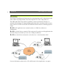
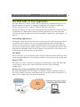
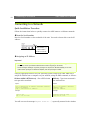
The old way of installing serial devices was by connecting them to PCs, either directly with
serial cables or by using modems. This often required a lot of PCs, long cables, etc.
The AXIS 2490 Serial Server makes it possible to connect serial devices directly to a
network without using a PC, thus providing applications with convenient remote access to
these resources via HTTP and TCP/IP. The illustration below shows the following physical
setups:
❶ to ❸ The PC application uses a network socket or a COM-Port redirector to
communicate.
❷ to ❹ PC to Serial Server to network. This can be used if you have an old application that
uses the serial port and when you can’t use a COM-port redirector.
❸ to ❹ Two serial devices connected to each other via a "virtual extension cable".
❶
❷
❹
❸
For more information, please refer to The AXIS 2490 in Your Application, on page 9.
AXIS 2490 User’s Manual
Overview
With its own built-in Web server, the AXIS 2490 allows direct access from any browser on
the network and provides full Web-based control of the management and configuration
functions.
The AXIS 2490 Serial Server supports high data rates and high throughput. It enables 10
Mbit and 100 Mbit Ethernet network access to serial devices using TCP/IP or HTTP as the
transport protocol.
One or two serial servers replace long cables and one PC, allowing dramatic reductions in
installation costs. The network solution also makes it possible to contact the
application/device remotely. As there are no physical confinements, the device can be
managed from anywhere within the network and controlled centrally, which is useful if
many people need access. Service engineers especially, will find it much more convenient
to troubleshoot devices remotely. System uptime will also be increased, as many moving
parts, i.e. the hard drives in the PC’s, are eliminated.
5
6
Overview
AXIS 2490 User’s Manual
Features and Benefits
Easy to Use - The AXIS 2490 is completely independent of any other server and requires no
special hardware or software. All you need is Netscape Navigator 4.x or above, or
Microsoft Internet Explorer 4.x or above. The AXIS 2490 has complete plug-and-use
functionality - all you need do is assign a valid IP address.
Simple Installation - The AXIS 2490 connects directly to Ethernet or Fast Ethernet networks,
Its Web-based interface greatly simplifes the installation process, and allows a seamless
integration into your networking and application environments.
Open Standards Environment - Supporting TCP/IP, HTTP and other protocols, the AXIS 2490
can be used in mixed environments, such as Windows, UNIX, Macintosh and OS/2.
Integrates easily into other WWW/Intranet applications and CGI scripts.
Simple Administration - Configuration and management via the product’s own Web-based
Administration Tools. Adjust the settings for; serial ports, security, the network etc,
directly from your browser.
Security - Data protection is normally implemented by your Network Administrator using
the unit’s security settings in combination with an organization’s Internet firewall. The
Administrator can decide whether individuals, groups, the whole company or the whole
world may access your Serial Server. The AXIS 2490 supports multi-user password
protection. Furthermore, when using the serial ports in TCP/IP mode, it is also possible to
specify Allowed Users and Allowed IP-addresses.
AXIS Technolgy - Axis’ renowned chipset technology is built on an open architechture that is
streamlined to provide device connectivity independent of any file server.
The AXIS 2490 is driven by a powerful AXIS ETRAX 32-bit RISC processor.
Linux Operating System - Including a Boa Web server, the Linux operating system provides a
stable platform for open-source development in future releases of the product. In
accordance with the GNU General Public License, Axis have published the kernel for this
product at http://developer.axis.com/. Axis would like to thank Paul Phillips, who wrote
Boa; and Larry Doolittle, who is now enhancing and maintaining this free software published at www.boa.org.
Complimentary Software - AXIS IP Installer - for quick installation of multiple units.
AXIS 2490 User’s Manual
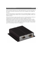
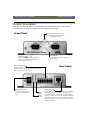
Product Description
Product Description
Read the following information to familiarize yourself with the AXIS 2490, making
particular note of where the connectors and indicators are located.
Front Panel
Two RS-232 serial ports, 9-pin male
D-SUB. Both ports support: RX, TX, RTS,
CTS, DSR, DTR, RI and CD.
Serial Number
Located on the underside label of the AXIS
2490, the serial number is identical to the
Ethernet address of the unit.
Screw Connector Block
One RS-485/RS-422 serial port on screw terminal block.
The block connector also provides an auxiliary connection
point for AC or DC power to the unit.
Power Supply Connector
A single Jack socket (PS-B) for
connection of AXIS 2490 power
supply.
Status
Indicator
Power
Indicator
Control Button
Used to reset the unit and to reinstate the
factory settings.
Rear Panel
Network Connector
The AXIS 2490 is designed for 10 Mbps Ethernet and 100 Mbps
Fast Ethernet networks and connects to the network via a
twisted pair category 5 cable (10baseT and 100baseTX) terminated using a standard RJ-45 connector. Supporting NWAY, the
AXIS 2490 detects the speed of the local network segment and
varies the speed of data communication accordingly, between
10 Mbps and 100 Mbps.
7
8
Assembling Your Unit
AXIS 2490 User’s Manual
Assembling Your Unit
The information provided in this section will help you unpack and assemble your product;
you are then ready to proceed with the installation and configuration of the product into
your application environment, as described in the following sections of this document.
Checking the Hardware Inventory
Unpack and check all the items against the itemized list below. You should contact your
dealer immediately if you find anything is missing or damaged.
Item
Model Variants
Part Numbers
Serial Server
AXIS 2490
0108-001-01
Europe
13267
UK
13268
Australia
13269
USA
13270
Japan
13936
Power Supply (PS-B)
4 x Rubber Feet
13933
4 x Screws
ST4.2X25 RXS-Z FZB
17645
4 x Plugs
30X3.5-4MM
17644
Printed Materials
Getting Started Guide AXIS 2490 R1.0 (or
later)
17298
AXIS 2490 User’s Manual
The AXIS 2490 in Your Application
The AXIS 2490 in Your Application
The AXIS 2490 can be used in a wide variety of applications. Installing directly onto an
Ethernet network, the product is completely independent and requires no additional
software, unless you plan on using a COM-port Redirector (see below).
This section will help you prepare for the installation and configuration of the unit. Not to
be regarded as a comprehensive catalog of possible applications, the section describes
several typical general applications. For more examples of applications, see Examples, on
page 35.
Networking Applications
Traditionally, serial devices have always been connected to PCs, either directly by cables or
via modems. Now, however, you can use an existing Ethernet network (LAN/WAN) to
connect to your serial device. Using the AXIS 2490 Serial Server as the link between the
serial device and the network, simply connect the device to the AXIS 2490, which in turn
plugs into the LAN/WAN. Lastly, set the IP address for the Serial Server and you’re ready
to start using your serial devices over the network.
Port Modes
The Serial Server has two operational modes: Generic TCP/IP and Generic HTTP. The mode
can be set independently for each serial port: (two RS-232 ports and one RS-422/485 port).
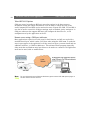
Generic TCP/IP
This mode is as a data connection for transparent communication, where the AXIS 2490
can act both as a server and a client. The mode can be used for the following
configurations:
Remote access using an application with network support
The AXIS 2490 supports the Telnet option for COM port control according to RFC2217.
This is one example of how the setup shown below can be used. Please see Protocols, on
page 27 for a complete list of the protocols supported.
9
10
The AXIS 2490 in Your Application
AXIS 2490 User’s Manual
Telnet RFC2217 Options
COM port control according to RFC2217 uses telnet options in the data stream to
encapsulate status and control information. It can be used to control the state of the
control outputs (RTS and DTR) and to monitor the state of inputs (CD, DSR, CTS and RI). It
can also be used to control the COM port settings, such as baudrate, parity settings etc. A
COM port redirector that supports RFC2217 will configure the baud rate etc., to the
configuration set by the application on the PC.
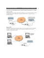
Remote access using a COM port redirector
Many applications require local serial ports for their function and will not work with a
networked serial port, which is what you’ll have when using the AXIS 2490. To make the
server’s ports appear to the application as if they were local ports, you must install and use
additional software - a COM Port Redirector. This software allows programs (especially
older ones) that use Windows serial port drivers to be used over a network. The application
itself runs as usual, with no modifications.
Note: For more information about COM-port Redirectors, please see the AXIS 2490 product pages on
the Axis website att www.axis.com.
AXIS 2490 User’s Manual
The AXIS 2490 in Your Application
2 Serial Servers used together create a "tunnel" and use the network as a "virtual
extension cable"
This alternative can be used to connect two serial devices or a serial device with a PC using
an application that uses COM ports. See Tunnel Communication, on page 36 for the
necessary settings.
Generic HTTP
The Generic HTTP mode gives you the ability to receive status/data and send commands
via HTTP. Communication via HTTP can be restricted to defined users or it can be
available for annonymous access.
11
12
Connecting to a Network
AXIS 2490 User’s Manual
Connecting to a Network
Quick Installation Procedure
Follow the instructions below to quickly connect the AXIS 2490 to an Ethernet network:
❶ Note the Serial number
Note the Serial number on the underside of the unit. You need to know this to set the IP
address:
Serial number same as
Ethernet number; e.g.
00408c100086 =
00-40-8c-10-00-86
❷ Assigning an IP Address
Important!
• Do not use the default IP address featured in the following examples when installing your AXIS 2490.
If in doubt, consult your Network Administrator before assigning an IP address.
• Server Privileges: Although no special privileges are required for Windows 95/98, you do need
Administrator privileges for Windows NT/2000, and Root privileges on UNIX.
Using an appropriate method for your operating system, assign your AXIS 2490 with a
unique IP Address from a computer on your network, using the ARP command, as follows:
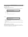
Windows 95/98 & NT/2000 only - Start a DOS window
and type these commands:
UNIX only - Type these commands in
your command line:
Syntax:
Syntax:
arp -s <AXISServer IP address> <Ethernet address>
<my PC IP address>
ping -t <AXISServer IP address>
arp -s <IP address> <Ethernet
address> temp
ping <IP address>
Example:
Example:
arp -s 172.21.1.200 00-40-8c-10-00-86
172.21.1.193
ping -t 172.21.1.200
arp -s 172.21.1.200
00:40:8c:10:00:86 temp
ping 172.21.1.200
You will now see the message ‘Request timed out...’, repeatedly returned in the window.
AXIS 2490 User’s Manual
Connecting to a Network
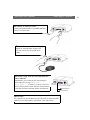
❸ Connect an Ethernet cable
Connect an Ethernet cable to your AXIS 2490 and
attach it to the network.
❹ Attach the external Power Supply
Attach the external Power Supply to the
unit and connect it to your local mains
supply.
❺ Wait for a reply from the unit and check the
Status indicator
Approximately 10-15 seconds after connecting the
power supply, the message ‘Reply from
172.21.1.200...’ - or similar, is returned in the DOS
window. Ensure that the Power Indicator is permanently
lit and that the Status Indicator flashes intermittently.
Status Indicator
Power Indicator
❻ Exit PING
The connection is now complete, and you are ready to access the AXIS
2490 from your Web browser, as described in the next section.
13
14
Connecting to a Network
AXIS 2490 User’s Manual
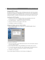
Verifying the Connection From Your Browser...
Having completed the procedure above, you should then verify the connection between the
AXIS 2490 and the network, as follows:
1. Start your browser (see note below) and enter the IP address of the AXIS 2490 in the
Location/Address field:
http://172.21.1.200/
The Welcome Page for your AXIS 2490 is now displayed:
Admin
Button
Installation
Wizard
2. Continue the setup process and configure your own application using the Installation
Wizard or click the Admin Button and use the Administration Tools, as described in
Configuring Your Serial Server, on page 18.
Important!
The Administration Tools can be used to change your username and password. Log on as an Administrator using the username root and default password pass. It is recommended that you change the root
password, since all Axis products are shipped with the same password as default. For further information, refer to System Security, on page 22.
AXIS 2490 User’s Manual
Connecting to a Network
Alternative Methods of Assigning the IP Address
In addition to the ARP command (as described earlier in this section), you can set the IP
address using an appropriate method for your operating system from the table below:
Important!
• Do not use the default or IP address featured in the following examples when installing your AXIS
2490. Acquire an unused IP address from your Network Administrator.
• Make sure the AXIS 2490 is powered up and attached to the network.
• Ethernet Address: The AXIS 2490 is pre-configured with a unique Ethernet Address based on the
serial number printed on the label on the underside of the unit; where the serial number typically
follows the format 00-40-8c-xx-yy-zz. You must know the Ethernet address to complete the installation.
Method
Operating Systems
Refer to...
AXIS IP Installer
Windows 95/98 and
NT/2000
Using the AXIS IP Installer, on page 16.
UNIX
Using BOOTP in UNIX, on page 17.
BOOTP
Requiring a BOOTP daemon on your system, this
method operates over the entire network. A
request to an active daemon initiates a search of
the boot table to find an entry matching the unit’s
Ethernet address. The daemon downloads the IP
address to the device if a match is found.
15
16
Connecting to a Network
AXIS 2490 User’s Manual
Using the AXIS IP Installer
The AXIS IP Installer is a Windows 95/98 & NT/2000 program that is ideal for setting the
IP addresses for multiple Axis’ networking products on your network. Also allowing you to
access the home page of any Axis ThinServer device connected to your network, this freely
distributed software is available for download from the Axis’ Website at www.axis.com.
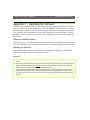
Installing the AXIS IP Installer:
1. Download the latest AXIS IP Installer software onto your desktop and run the
Setup_IPInstaller.exe program to start the installation.
2. The AXIS IP Installer - Setup dialog is displayed on the screen.
3. Follow the instructions as they appear on the screen.
4. Click Finish to complete the installation.
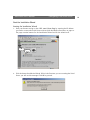
Setting the IP Address with the AXIS IP Installer:
1. Run the AXIS IP Installer from the Start menu. The AXIS IP Installer dialog is
displayed on the screen.
2. Restart your AXIS 2490.
3. Select the serial number of your AXIS 2490 from the list. The serial number is identical
to the unit’s Ethernet address.
4. Enter the desired IP address. Click Set IP address. The IP address will now be set.
5. To access the home page of the AXIS 2490, click Home page of selected Axis-server...
You can now configure the AXIS 2490 according to your requirements.
6. Click OK to exit the program.
For more help during the installation of the IP address, click Help or F1.
AXIS 2490 User’s Manual
Connecting to a Network
Using BOOTP in UNIX
Follow these steps to use the BOOTP method:
1. Append the following entry to your boot table. This is typically done using the file
/etc/bootptab:
<host name>:ht=<hardware type>:vm=<vendor magic>:\
:ha=<hardware address>:ip=<IP address>:\
:sm=<subnet mask>:gw=<gateway field>
where:
ht
vm
ha
ip
sm
gw
= ether
= rfc1048
= The Ethernet address of the AXIS 2490
= The IP address of the AXIS 2490
= The subnet mask
= The default router address
Example!
myserver:ht=ether:vm=rfc1048:\
:ha=00408c100086:ip=172.21.1.200:\
:sm=255.255.255.0:gw=172.21.1.1
2. If necessary, update your host table and alias name databases according to the
requirements of your system.
3. If it is not already running, start the BOOTP daemon. This is typically done using the
command bootpd.
4. Restart the AXIS 2490 to download the IP address, default router address, and subnet
mask.
Mapping a Host Name to the IP Address
If you are using host names, you can also map a unique host name to the acquired IP
address. Refer to your system manuals or Network Administrator for instructions on how
to perform the name mapping on your particular system.
17
18
Configuring Your Serial Server
AXIS 2490 User’s Manual
Configuring Your Serial Server
The AXIS 2490 is configured and integrated into your application environment using the
Web-based Installation Wizard or the Administration Tools. It is assumed that you have
connected your Serial Server prior to commencing with this section. If not, please refer to
Connecting to a Network, on page 12.
Important!
On-line help
is available from most pages within the AXIS 2490 Web interface. Containing comprehensive details on all product parameters; this information is your first point of reference when configuring and managing the unit, and is a particularly useful reference when resolving any administration
queries. The help system is stored internally in the AXIS 2490.
When accessing the Administrator Tools for the first time during a session, you are prompted for the
username and password. Log on as an Administrator using the username root and default password pass.
It is recommended that you change the root password, since all Axis products are shipped with the same
password as default. For further information on this, refer to System Security, on page 22.
Complete the Basic Installation Using the Installation Wizard
Having connected your AXIS 2490 directly to a local area network, you should now use
the Installation Wizard to complete the most basic setup. This wizard will help you make
settings for the following:
• Administrators, Users and Passwords.
• The host name, IP address, subnet mask and other basic network settings.
Important!
Prior to accessing the Installation Wizard or Administration Tools over a network, you must first set the
Internet address, as described in Connecting to a Network, on page 12.
AXIS 2490 User’s Manual
Configuring Your Serial Server
Start the Installation Wizard
Starting the Installation Wizard
1. Start your browser and go to the AXIS 2490’s Home Page by entering the IP address
you used to connect the Serial Server with in Quick Installation Procedure, on page 12.
The page contains buttons for the Installation Wizard and for the Admin tools.
Admin
Button
Installation
Wizard
2. Click the button Installation Wizard. If this is the first time you are accessing the Serial
Server you will see this message. Click OK to proceed.
19
20
Configuring Your Serial Server
AXIS 2490 User’s Manual
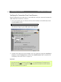
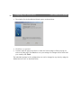
3. The window for the Installation Wizard opens, as shown below.
4. Click Start > to proceed.
5. Continue with the pages that follow to make the basic settings as listed on page 18,
and on the final page, click Finish to save your settings. No changes will be made until
you actually click Finish.
The individual settings in the configuration can now be changed at any time by using the
Administration Tools, as described below.
AXIS 2490 User’s Manual
Configuring Your Serial Server
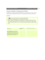
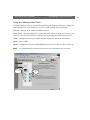
Using the Administration Tools
The administration tools are accessed from the Welcome Page (see above) by clicking the
Admin button. The tools found here are used to make settings for the following:
Network - Settings for IP addresses, DNS servers etc.
Serial Server - General settings for e.g. date and time, security settings etc. From here you
can also restart the Serial Server or reinstate factory settings, should this be necessary.
COM1 - Configure the serial port COM1 for baud rate, mode, protocols, modems etc.
COM2 - As for COM1.
RS485 - Configure the serial port RS485/RS422 for protocols, baud rate, flow control etc.
Note: It is recommended that you change the password for your AXIS 2490 as soon as possible.
On-line
Help
Click the item
to configure
The current
mode
21
22
Configuring Your Serial Server
AXIS 2490 User’s Manual
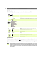
Tools Overview
The table below provides a one-stop overview of the Administration Tools.
Network
Sub-Button
Detailed View
Description
Configure TCP/IP, SMTP, DHCP, BOOTP and DNS network settings.
General
Sub-Button
Security
Description
Set the Administrator password and add or delete users and their passwords.
See a listing of the configured parameters.
View the log file automatically created by the AXIS 2490.
Shows various important information about status and settings.
View the final notes from the product’s release.
Restart the AXIS 2490.
Reset the unit to the factory defaults.
COM1/2
Sub-section
Select Mode
Settings for selected Mode
RS422/485
Sub-section
Select Mode
Settings for selected Mode
Settings
Select Generic TCP/IP, Generic HTTP or Off. This selection determines the
configurable parameters that appear below this setting.
Various communication settings such as: baud rate, data bits, stop bits,
parity, flow control etc.
Settings
Select Generic TCP/IP, Generic HTTP or Off. This selection determines the
configurable parameters that appear below this setting.
Various communication settings such as: baud rate, data bits, stop bits,
parity, flow control etc.
System Security
To prevent unauthorized use, the AXIS 2490 supports user-level password protection and
access is restricted to defined users only. System Administrators have exclusive access to
the server’s Administration Tools and can determine the registration and access rights for
all users.
Note: Although, the default username and password (set to root and pass respectively) can be used for
logging in to the unit for the first time, it is strongly recommended that you change the password
for your AXIS 2490 as soon as possible - since all Axis products are shipped with the same password as default.
AXIS 2490 User’s Manual
Configuring Your Serial Server
User Access Rights
As a user with Administrator privileges, you can click the Security button to add,
configure and delete further usernames and passwords, including ones with Administrator
privileges.
Important!
• To restrict open access via HTTP, simply register a single authorized user: this effectively revokes the
anonymous user service and restricts access to specified users. If the anonymous user service is
satisfactory for your application, simply do not add any users.
• Please change the default password for the Administrator (root) as soon as possible. This will enable
the unit’s security function.
Reinstating the Factory Default Settings
In certain circumstances, it may be necessary to reinstate the Factory Default settings for
your AXIS 2490. This is performed by clicking the appropriate button within the
Administration Tools, or by pressing the Control Button. Follow the instructions below to
reinstate the product factory default settings using the Control button:
1. Switch off the AXIS 2490 by disconnecting the power cable.
2. Press and hold in the Control Button, and reconnect the power supply cable.
3. With the Control Button pressed, the Status Indicator will now flash briefly and then
go out. When the Status Indicator has been out for about 5 seconds, release the Control
Button. When the Status Indicator starts to flash again after approximately 5 seconds,
the AXIS 2490 will then have been reset to its default setttings.
Notes: •Reinstating the original default settings will cause all of the unit’s parameters to be reset.
•It is also possible to restart the unit with the Restart Button on the the Admin pages.
•Refer to Alternative Methods of Assigning the IP Address, on page 15 for information on how to set the
IP number in the product.
23
24
Troubleshooting
AXIS 2490 User’s Manual
Appendix A - Troubleshooting
This appendix provides useful information to help you to solve any problem you might have with
your AXIS 2490. Fault symptoms, possible causes and remedial actions are provided in a quick
reference table.
PINGing Your IP Address
By sending a packet to the specified address and waiting for a reply, the PING utility can
determine whether a specific IP address is accessible. It also provides a particularly useful
method for confirming addressing conflicts with your AXIS 2490 on the network.
Having disconnected your AXIS 2490, follow the instructions below in association with
Symptoms, Possible Causes and Remedial Actions, on page 25, and run the PING utility to
troubleshoot TCP/IP problems on your network:
1. Start a DOS window.
2. Type ping x.x.x.x, where x.x.x.x is the IP address of the AXIS 2490.
3. The subsequent replies will provide an explanation as to the cause of the problem.
Replies can be interpreted as defined in the table below:
PING Reply
Interpretation and recommendation
bytes = 32 time = 2 ms......
The IP address is already in use. You must obtain a new IP address.
destination host unreachable
The AXIS 2490 is not accessible within your subnet.
You must obtain a new IP address.
request timed out
This IP address is not used by anyone and is available for use with your
AXIS 2490.
How to test your setup
Connect a serial port on the 2490 to a serial port on the PC using a null modem cable.
Start a terminal program on the PC that accesses the serial port, e.g. Hyper Terminal in
Windows or minicom or cua in Linux.
Start a telnet session to the Serial Server IP address and the corresponding TCP port for the
chosen serial port (default 4000, 4001, 4002).
In Windows, select Run... from the Start Menu and type: telnet ipaddress portnr,
for example: telnet 10.13.7.12 4000.
Everything you type should appear in the terminal program when you press Enter, and
everything you type in the terminal program should appear in the telnet window.
AXIS 2490 User’s Manual
Troubleshooting
Test a COM Port Redirector
Configure the COM Port Redirector to connect to the host and the port. Enable or disable
the use of telnet options (RFC2217), depending on the settings in the AXIS 2490 Serial
Server. Start a second instance of the terminal program instead of using telnet. Whatever
you type in the terminal programs should appear in the other terminal window.
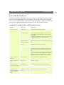
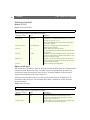
Symptoms, Possible Causes and Remedial Actions
Symptoms
The AXIS 2490 cannot be
accessed from a browser.
Possible causes
Remedial actions
The IP address is already used Disconnect your AXIS 2490 from the network, run the PING utility
by another device.
and follow the appropriate recommendations.
The IP address is located
within a different subnet.
Run the PING utility. If the utility returns “no response” or similar,
in Windows 95/98 or Windows NT/2000, you should then check
that the IP address for your AXIS 2490 is on the same subnet as
your workstation.
If these subnets are different, the IP address cannot be set from the
workstation. Please contact your network administrator.
In Windows 95, the ARP
table was empty when you
tried to set the IP address.
If the table is empty, re-install the product ensuring that the IP
address for your own PC is also used. Type arp -a to view the ARP
table.
Proxy server.
Try disabling the proxy default in your browser.
Other networking problems.
Try replacing your network cable.
Test the network interface of the product by connecting a local
computer to the unit, using a standard Crossover (hub-to-hub)
Cable.
If the above actions don’t solve the problem, the AXIS 2490 may be
faulty. In this case, try to localize the problem by connecting the
AXIS 2490 to the serial port of a local computer, using a Null
Modem Cable; and report your findings to your local distributor.
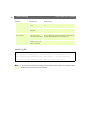
The Power indicator is not
constantly lit.
Faulty power supply.
Verify that you are using an AXIS PS-B power supply.
The Status indicator flashes
rapidly.
Hardware failure.
Contact your Axis dealer.
Your AXIS 2490 works
locally, but not externally.
Firewall protection.
Check the Internet firewall with your system administrator.
Default routers required.
Check if you need to configure the default router settings.
The IP settings in the 2490
are wrong.
Check the IP number, router and netmask settings.
"Unable to connect to
remote host: Connection
refused" or similar error
message.
25
26
Troubleshooting
Symptoms
An established connection is
closed immediatly.
AXIS 2490 User’s Manual
Possible causes
The TCP port number is
wrong.
Remedial actions
Make sure you use the same port number the 2490 is configured
for.
The 2490 is not in Generic
TCP/IP mode.
Check the settings in the 2490.
Someone else is already
using the port and has
connected to the Axis 2490.
Select "View Log FIle" in the Server settings to see if anyone else
has connected. See the example Log File Below. You may want to
configure "Allowed IP addresses" and restart the unit.
You have enabled "Allowed
IP addresses" but your IP
address is not allowed.
Check the settings in the 2490.
Sample Log File
Jan
1 03:56:20 ado-6 sersrvd[19]: Port COM1 server 12 connected from10.13.7.12
Jan
1 03:56:29 ado-6 sersrvd[19]: Port COM1 server 13 connected from 10.13.7.13
Jan
1 03:56:29 ado-6 sersrvd[19]: Port COM1 close(13) - too many connections.
Jan
1 04:27:07 ado-6 sersrvd[19]: Port COM1 net close(12) rx: 2 tx: 0
Note: If you still have a problem after reading this information, please contact your reseller or check
the FAQ on the Axis Website at www.axis.com.
AXIS 2490 User’s Manual
Technical Specifications
Appendix B - Technical Specifications
System Requirements
TCP/IP on Windows 95, 98, NT/2000, Linux, UNIX, Mac and several others. Microsoft
Internet Explorer 4.x or higher, or Netscape 4.x or higher.
Protocols
ARP, BOOTP, TCP, IP, HTTP, ICMP, FTP, and DNS. The serial server supports telnet options
for COM port control according to RFC2217.
Network Management
Configuration and status via standard HTTP browser. Microsoft Internet Explorer 4.0 or
Netscape 4.0 or higher. Possible to use FTP to upload/download configuration files.
Network Connection
1 RJ-45 connector (Category 5 shielded or unshielded twisted pair cable) for 10BaseT
Ethernet or 100Base TX Fast Ethernet. (Shielded cable recommended for industrial
environments).
Additional Software
A COM Port Redirector, which allows existing Windows software to access networked
attached serial devices, can also be used with the serial server. For more information about
COM-Port Redirectors, please see the AXIS 2490 product pages at www.axis.com.
The Axis IP-installer can be used to assign IP-addresses.
Security
User-level password protection. It is also possible, when using the ports in TCP/IP mode, to
specify Allowed Users and Allowed IP addresses. These settings will disallow all other IP
addresses and users.
Software Updates
Flash memory allows central and remote software updates over the network using FTP over
TCP/IP. All software upgrades are available free of charge from the product pages for the
AXIS 2490 at the Axis Website www.axis.com.
CPU
32 bit RISC processor (ETRAX 100).
27
28
Technical Specifications
AXIS 2490 User’s Guide
Memory
Flash Memory - 2MB.
RAM - 8MB.
Serial Connectors
Two RS-232 serial ports, 9 pin MALE D-SUB. Both support: RX, TX, RTS, CTS, DSR, DTR,
RI and CD. Supported speeds of up to 115200 bps.
MALE 9-pin DSUB (RS-232 levels) (X3 and X2)
1 I /CD
2 I RXD
3 O TXD
4 O /DTR
56 I /DSR
7 O /RTS
8 I /CTS
9 I /RI
Carrier Detect
Receive Data
Transmit Data
Data Terminal Ready
GND
Data Set Ready
Request To Send
Clear To Send
Ring Indicator
1 RS-485/422 serial port on screw terminal block:
Supports speeds of up to 1843200 bps.
1 AC
2 AC
3 GND
4 GND 100 Ohm
5 RX/TX- A
6 RX/TX+ B
7 TX8 TX+
Delimitations for RS-485/422
RS-485 and RS-422 are similar, although there are differences in the electrical
specification. Most driver circuits are compatible with both, at least for the receiver part.
The AXIS 2490 Serial Server is primarily designed to work with RS-485 devices, although
it will probably work with most RS-422 devices as well. A terminating 100-120 Ohm
termination resistor might be needed between RX+ and RX-.
Operating Temperature
+5 to +50 ° C.
AXIS 2490 User’s Manual
Technical Specifications
Humidity
8-80% RHG, non-condensing.
Dimensions and weight
Height: 27mm
Width: 112mm
Length: 110mm
Weight: 0.32kg
Power Supply
Power: 9-24 V AC (or DC), 6 VA, via external power supply (PS-B). Typical power
consumption is 2,5-3,5 VA.
Mechanical Design
Stable aluminum metal casing, with screwholes for wall mounting.
EMC and Safety approval
The AXIS 2490 Serial Server fulfills both industrial and light industrial/commercial EMC
standards for emission and immunity, and Standards for Safety.
Immunity Standards:
EN 55024:1998,
EN 50082-1:1997
EN 6100-6-2:1999
Emission Standards:
EN 55022:1994 (CISPR 22:1993 + A1: 1995 + A2: 1996), Class B + A1: 1995 +A2: 1997.
FCC Part 15, Subpart B, Class A.
FCC Part 15, Subpart B, Class B, demonstrated by compliance with EN55022: 1994, Class B.
AS/NZS3548 (C-Tick). Demonstrated by compliance with CISPR 22:1993.
Safety Standards:
EN 60950, UL, CSA.
Warranty
1 year. Please register your product at http://warranty.axis.com.
AXIS Chipset Technology
The AXIS 2490 Serial Server comprises Axis' own ETRAX 100 32-bit RISC processor and
embedded Linux. See http://developer.axis.com for info about our embedded Linux.
29
30
Technical Specifications
AXIS 2490 User’s Guide
All specifications are subject to change without prior notice.
AXIS 2490 User’s Manual
Updating the Software
Appendix C - Updating the Software
The AXIS 2490 software is stored in Flash memory. This memory is provided by a silicon
chip that, just like any other ROM device, retains data content even after power is removed.
Flash memory is unique because it allows its data to be erased and re-written. This means
you can install software updates for your AXIS 2490 as they become available - without
having to replace any parts. New software can be simply loaded into the AXIS 2490 over
the network.
Obtaining Updated Software
The latest version of the AXIS 2490 software is available free of charge from Axis or from
your local distributor. You can obtain this software over the Internet from www.axis.com.
Updating the Software
The AXIS 2490 Flash memory is updated over the network using FTP. See the detailed
instructions supplied with each new software release.
Important!
• Always read the upgrade instructions available with each new release, prior to upgrading your software.
• Downloading normally takes between 30 seconds and 10 minutes, although it can take longer. After
starting the download, you should always wait at least 20 minutes before power-cycling the AXIS
2490 - even if you suspect the download procedure has failed.
• In controlled environments, flash memory upgrades provide a very safe method of updating the
software. However, flash products can become damaged if the upgrade operation is not performed
correctly. Your dealer reserves the right to charge for any repair attributable to faulty upgrading by
the user.
31
32
The Unit Connectors
AXIS 2490 User’s Manual
Appendix D - The Unit Connectors
This section provides a detailed overview of the Serial Server’s serial port connections: the
two RS-232 Serial Ports, and the IO Block Connector, including the RS-422/485 Port.
The Serial Connectors
The two RS-232 serial connectors provide the physical interface for connecting serial
devices to the AXIS 2490 and thus to the network.
RS-232 Connections
Two 9 pin male D-sub connectors provide the physical connections for the RS-232 serial
interface of the AXIS 2490. These connectors are for use with serial devices at speeds of up
to 115200 bps. The RS-232 ports (3 outputs and 5 inputs) support all status and control
signals.
The male connector is the same as on a PC, i.e. a DTE. The RS-232 driver supports up to
115200 bps. Wiring distances should be limited to about 60 meters (200 feet) for
asynchronous data and to about 15 meters (50 feet) on synchronous lines.
COMx D-SUB 9 connector (RS-232 levels)
Pin
Function
1
I CD (Carrier Detect)
2
I RXD (Receive Data)
3
O TXD (Transmit Data)
4
O /DTR (Data Terminal Ready)
5
- GND (Ground)
6
I /DSR (Data Set Ready)
7
O /RTS (Request To Send)
8
I /CTS (Clear To Send)
9
I /RI (Ring Indicator)
The Pinout for the male RS-232
connector on the Serial Server
1
2
6
4
3
7
8
5
9
The IO Connector Block
The AXIS 2490 has an I/O Connector (screw terminal blocks) for connecting RS-485/422,
or for use as an alternative power supply.
RS-485
RS-485 is a bi-directional, half-duplex standard for transmitting data over multi-drop
communications line. Supporting up to 32 drivers and 32 receivers over a single twisted
pair cable, the maximum cable length should not exceed 1220 meters (4000 feet). Typically
used for connecting a single master (e.g. a PC) to several addressable devices over the same
cable. The master decides which slave speaks and the slaves only speak when spoken to, by
raising RTS. The Axis 2490 will act as either a master or a slave, depending on how
AXIS 2490 User’s Manual
The Unit Connectors
communication is initiated. RS-485 is similar to RS-232, but without a signal ground and
with double-wired transmit and receive data. The wires are TxD+, TxD-, RxD+ and RxD-.
Data detection is done by measuring the voltage difference between the positive and
negative line. This eliminates disturbance by interference, because interference appears
identically on all lines simultanously. This means greater distances can be covered than
with RS-232.
RS-422
RS-422 is similar to RS-485, but uses 2 pairs of wires (4-wire RS-485). This provides a
full-duplex communication line that supports cable lengths up to 1220 meters (4000 feet).
RS-422 is a so-called 'differential' interface. This means that the signals are transported
over balanced circuits. In practice this means that you will have two dedicated wires for
each signal. Data is coded as a voltage difference between the two wires. Each signal has to
be transported over one pair. Because these wires have to be a twisted-pair, any noise
picked up will influence the voltage level of both wires in the same way and the difference
between the wires will not be affected. Thus the information is much less receptive to noise
than when using RS-232.
Delimitations for RS-485/422
RS-485 and RS-422 are similar, although there are differences in the electrical
specification. Most driver circuits are compatible with both, at least for the receiver part.
The AXIS 2490 Serial Server is designed primarily to work with RS-485 devices, although
it will probably work with most RS-422 devices as well. A terminating 100-120 Ohm
termination resistor might be needed between RX+ and RX-.
Physical Connections on the I/O Connector Block
Screw terminal connector with 8 poles:
•
•
•
•
•
(Phoenix MC 1.5 - 3.81 mm)
4 pins for RS-422/485 TX+, TX-, RX+, RX1 pin for RS-485/422 ground (connected to GND with 100 ohm resistor)
1 pin for GND
2 pins Alternative power (9-24V AC)
33
34
The Unit Connectors
AXIS 2490 User’s Manual
The RS-485/422 port
A 4-wire RS-422/485 port (one TX pair and one combined RX/TX pair).
The RX port can be used for both RX and TX (controlled by RTS) and for half-duplex
RS-485.
The port can be used in any of these configurations:
• Full-duplex RS-422 (4-wire) or
• 4-wire RS-485 or
• Half-duplex RS-485 (2 wire)
The port is compliant with EIA-RS-485 up to 1843200 bps.
RS-485/422 Serial Port on screw terminal block
Pin
Function
1
AC
2
AC
3
GND (Standard Ground)
4
GND100 Ohm (Connected to Gnd via 100 Ohm
resistor)
5
RX/TX -A
6
RX/TX +B
7
TX -
8
TX +
AXIS 2490 User’s Manual
Examples
Appendix E - Examples
Applications
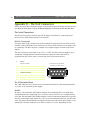
Access Control Devices
Many buildings nowadays do not use door keys for controlling access, but instead use
magnetic cards and card readers at each door or access point. Entering a code on a keypad
is another alternative. Both the card readers and the keypads are connected to a computer
that opens/unlocks the door.
A common way of installing a large number of card readers in a building with several
floors has been to use a PC for each card reader and connect them via long serial cables.
Every card reader and connected PC must then be provided with the correct information
about all the employees who require access. Some people might have access to all doors
while others only have admission to a certain floor.
To cancel lost cards and to issue new ones, all the PCs must be given this information. This
will be necessary each time someone leaves the company and when new employees are
hired.
A much better solution would be to connect the card readers to a network. Even if a
network has to be installed, it will still be cheaper than running long serial cables to each
card reader.
The network solution has many advantages. From anywhere in the network it is possible to
send the right commands to all of the card readers, and it’s also easy to update the system.
In the case of a stolen card, it can easily be invalidated from a remote location.
It’s also possible to connect a camera to each card reader. Every time someone enters the
door with a magnetic card a photo is taken and stored. If a stolen card is used, the person
using the card will be revealed. It is also possible to connect an alarm system to prevent
break-ins.
Remote access to keypads and card readers makes work much easier for everyone
concerned. Using the Internet, there are no physical limits anymore. Even repairs can be
made from a distance. Service engineers can work from home if they are on call at night or
at the weekend.
35
36
Examples
AXIS 2490 User’s Manual
Surveillance and Alarm Systems in Buildings
In places such as lifts and toilets, there might be a push button to activate a distress signal
in case of an emergency. The button would be linked directly to the network via a serial
server.
Barcode Readers
Barcodes and barcode readers can be found in many different locations, such as shops and
factories. In production plants, different parts could have a barcode which would show
where it belongs. In the case of car production, it would be possible to see who has ordered
a particular car and what it will look like when finished. Whether the car should be fitted
with e.g. airbags, the car’s color etc, is all information that could be contained in the
barcode.
If the barcode reader is connected to a network via an AXIS 2490 Serial Server, the
individual car seller will have access to information about possible delays and delivery
dates. The information about a specific car ordered by a customer will be accessible at all
stages during production.
Remote Troubleshooting
Suppose a device malfunctions and the manufacturer and/or service technicians are
located on the other side of the world. Via the AXIS 2490 Serial Server it would be possible
to connect the device’s serial port to the Internet, where it will then be available to service
engineers, who will be able to find out what is wrong with the device and recommend a
course of action.
Tunnel Communication
Any two devices that can connect to each other via a serial cable can also be connected via
two Serial Servers over a network. Assuming the two servers have the addresses 1.2.3.1
and 1.2.3.2, the following settings are then needed:
1.2.3.1 uses Connect To: 1.2.3.2 and uses the Allowed IP Address: 1.2.3.2.
1.2.3.2 in turn uses Connect To: 1.2.3.1 and Allowed IP Address: 1.2.3.1.
Both devices must use the same Listener Port or it must be specified in the Connect To
parameter, e.g. Connect To: 1.2.3.1:4000.
Telnet Options must have the same value on both units; Yes if RFC2217 functions are
required.
AXIS 2490 User’s Manual
Examples
Climate Control
Monitoring of indoor climates includes heating, ventilating and air conditioning systems.
These systems are usually connected to computers via long serial cables. A more
convenient solution is if the building’s control systems are connected to a network via
AXIS 2490 Serial Servers. This enables remote access and monitoring from anywhere in
the network. Service engineers can also locate and identify errors. In some cases they’ll
even be able to solve the problem directly over the network, and even if they can’t, they’ll
know which equipment and spare parts are needed.
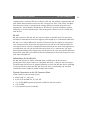
Pan/Tilt/Zoom (PTZ) Applications
As a person approaches a building, this is seen on a computer screen. An operator clicks on
the image and a camera redirects and zooms in. An enlarged image of the person is
displayed on the screen.
This is a realization of a Pan/zoom/tilt device and a camera connected to a network via
AXIS 2490 Serial Servers. The camera can be controlled by simply using a browser and
clicking on control buttons in the web page. Another alternative is to activate the proper
camera positions by using an image map of the area in question, as in the example above.
Wherever something interesting happens, you only need to click on the image. The PTZ
device will redirect the camera to the chosen spot.
37
38
Examples
AXIS 2490 User’s Manual
Serial port control
Method: GET/POST
Syntax: Control Serial Port
http://<AXISserver>/axis-cgi/com/serial.cgi?<parameter>=<value>[&<parameter>=<value>...]
The following parameters and values are available:
<parameter>=<value>
port=<int>
write=<string>
Values
1,2,3
<bytestring>
Description
This parameter selects the COM port.
"<bytestring>": hex coded bytes with values of {0, 1, 2, 3, 4, 5, 6, 7,
8, 9, A, B, C, D, E, F, a, b, c, d, e, f}
writestring=<string>
<url encoded string>
Writes the specified data string to the selected serial port. Max
string length: 128 bytes.
Writes the url encoded string to the selected serial port.
read=<int>
<n>
Max string length: 128 bytes.
Reads n bytes from the selected serial port.
wait=<int>
1 - 9000
timeout=<int>
1-9
info=<int>
1
The returned data will be hexadecimal coded and placed between
#s (e.g. #3A#).
Specified in milliseconds. Used together with the "read" parameter.
A read is terminated when the specified number of bytes is read or
when the wait period has ended.
Specified in seconds. Used together with the "read" parameter. A
read is terminated when the specified number of bytes is read or
when the timeout has expired.
Returns a description of this CGI-request.
Open serial port
This CGI makes it possible to open the serial port using the HTTP protocol. Authentication
is handled by the Web server. After an initial connect command from the client, the
connection is kept alive until the client closes it. A limited number of clients may be
connected concurrently to the same serial port.
After the connection has been set up, data sent from the client to the Web server is
forwarded to the serial port, and incoming serial data is returned to all the currently
connected clients.
Syntax: open serial port
http://<servername>/axis-cgi/com/serial.cgi?<parameter>=<value>[&<parameter>=<value>...]
The following parameters and values are available:
<parameter>=<value>
port=<int>
unit=<int>
Values
1,2,3
1,2,3
connect=<string>
yes
Description
Select COM port.
Selects the source AXIS server. If omitted, and the "port="
command is also ommitted, the default AXIS server is used to
determine the serial port to use.
Makes the AXIS server keep the connection open, and start acting
as a link between the client and the serial port.
AXIS 2490 User’s Manual
Examples
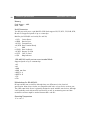
Simple TCP Client Program Example for a Generic TCP/IP port
This example is for use on Linux and other UNIX variants.
Note: The example provided here is intended only as a guideline for developing your own application
and there is NO guarantee that the code will work in your particular application. All of the code
shown here is subject to change without prior notice.
printf("Connecting to %s:%u...\n", host,
portnr);
fd = client_connect(host, portnr);
* Compile with: gcc -Wall tcpclient.c -o
if (fd > 0) {
tcpclient
int num_sent;
int num_rec;
* Axis Communications AB, Lund Sweden
char txstring[]="This is a test string\r\n";
*/
int txlen = strlen(txstring);
#include <string.h>
char rx_buf[RXBUFSIZE];
#include <unistd.h>
/* read, write, close */
int rx_tot = 0;
#include <stdlib.h>
printf("Connected ok\n");
#include <stdio.h>
#include <netinet/in.h> /* sockaddr_in,
/* We are connected */
IPPROTO_TCP */
num_sent = write(fd, txstring, txlen);
#include <netdb.h>
/* gethostbyname */
if (num_sent != txlen) {
#include <errno.h>
/* errno etc. */
perror("Failed to write all");
#define RXBUFSIZE 1000
if (errno == EAGAIN)
{
/* Create TCP connection to host:portnr, return
/* We can send remaining bytes */
filedescriptor > 0 if ok */
}
int client_connect(const char* host, u_short
}
portnr)
printf("Sent %i bytes: '%s'\n", num_sent,
{
txstring);
int s = 0;
printf("Reading 30 bytes data...\n");
struct sockaddr_in server;
struct hostent *hp;
/* Read data until we got 30 bytes */
while (fd && rx_tot < 30) {
hp = gethostbyname(host);
num_rec = read(fd, &rx_buf[rx_tot],
if (hp != NULL) {
30-rx_tot);
bzero((char *) &server, sizeof server);
if (num_rec > 0) {
bcopy(hp->h_addr, (char *) &server.sin_addr,
/* Ok */
hp->h_length);
rx_tot += num_rec;
server.sin_family = hp->h_addrtype;
/*
rx_buf[rx_tot]='\0';
Protocol family */
printf("rx_tot: %i '%s'\n", rx_tot,
server.sin_port = htons(portnr);/* Port number rx_buf);
*/
} else {
s = socket(AF_INET, SOCK_STREAM, 0);
perror("Failed to read\n");
if (s < 0) {
if (errno != EAGAIN)
printf("error in socket\n");
{
}
printf("Closing\n");
if (connect(s, (struct sockaddr *) & server,
close(fd);
sizeof server) < 0) {
fd = -1;
printf("connect() error in bind\n");
}
s = 0;
}
}
}
}
if (fd > 0) {
return s;
close(fd);
}
}
int main(int argc, char **argv)
} else {
{
perror("Failed to connect!\n");
int fd;
}
u_short portnr = 4000;
return 0;
const char *host;
}
* This uses blocking sockets without select(),
use select() for more complex applications.
if (argc < 2) {
printf("Usage: tcpclient host [port]\n");
printf(" port is default 4000\n");
exit(1);
}
host = argv[1];
if (argc > 2) {
portnr = atoi(argv[2]);
}
Continued.....
39
Index
40
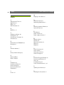
Index
A
Administration Tools 21
Applications 9
ARP 12, 25
AXIS IP Installer 16
B
BOOTP 15, 17
C
COM port redirector 10
Configuration 18
Connecting to a network 12
Connectors 32
D
Delimitations for RS485/422 33
Description 7
E
Ethernet address 15
F
Factory Default Settings 23
G
Generic HTTP 11
Generic TCP/IP 9
I
Installation 12
Installation Wizard 18
Internet address 25
IO Connector Block 32
IP Address 12
L
Linux 6, 27
AXIS 2490 User’s Manual
M
Mapping a Host Name 17
N
Network Connector 7
Networking Applications 9
O
Obtaining updated software 31
Open serial port 38
P
Port Modes 9
Power indicator 25
Power supply connector 7
R
Remote access 9
RFC2217 10
RS232 Connections 32
RS422 33
RS485 32
S
Serial Connectors 32
Serial number 7
Serial port control 38
Server Privileges 12
T
TCP Client Program Example 39
Technical specifications 27
Telnet 10
Troubleshooting 24
Tunnel Communication 11, 36
U
Updating the software 31
V
Verifying the Connection 14