1
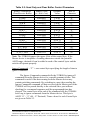
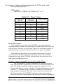
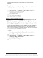
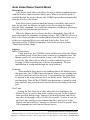
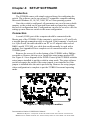
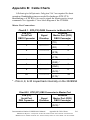
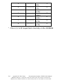
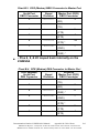
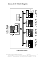
Buffered Smart Switch
Model 232BSS4
Documentation Number: 232BSS4-0812
This product designed and manufactured in Ottawa, Illinois USA
of domestic and imported parts by
707 Dayton Road -- P.O. Box 1040 -- Ottawa, IL 61350 USA
Phone (815) 433-5100 -- General Fax (815) 433-5105
Phone (815) 433-5100 -- General Fax (815) 433-5105
Website: www.bb-elec.com
Sales e-mail: [email protected] -- Fax (815) 433-5109
Technical Support e-mail: [email protected] -- Fax (815) 433-5104
European Headquarters
B&B Electronics
Westlink Commercial Park -- Oranmore, Co. Galway, Ireland
Phone +353 91-792444 -- Fax +353 91-792445
Website: www.bb-europe.com
Sales e-mail: [email protected]
Technical Support e-mail: [email protected]
B&B Electronics Mfg. Co. Inc. -- July 2007
Manual Documentation Number: 232BSS4-0812
B&B Electronics Mfg Co Inc – 707 Dayton Rd - PO Box 1040 - Ottawa IL 61350 - Ph 815-433-5100 - Fax 815-433-5104 – www.bb-elec.com
B&B Electronics – Westlink Commercial Park – Oranmore, Galway, Ireland – Ph +353 91-792444 – Fax +353 91-792445 – www.bb-europe.com
This document contains information that is proprietary and confidential to B&B
Electronics Mfg. Co. Inc. The methods described herein are for the exclusive use of
B&B Electronics authorized personnel. Any unauthorized use or dissemination of the
information contained in the document is strictly forbidden.
B&B Electronics Mfg Co Inc – 707 Dayton Rd - PO Box 1040 - Ottawa IL 61350 - Ph 815-433-5100 - Fax 815-433-5104 – www.bb-elec.com
B&B Electronics – Westlink Commercial Park – Oranmore, Galway, Ireland – Ph +353 91-792444 – Fax +353 91-792445 – www.bb-europe.com
Table of Contents
CHAPTER 1 – INTRODUCTION............................................................ 1
SPECIFICATIONS ........................................................................................ 2
DEFAULT PARAMETERS ............................................................................ 2
CHECKLIST ................................................................................................ 3
CHAPTER 2: OPERATION .................................................................... 5
SYMBOLS AND CONVENTIONS ................................................................... 5
LED INDICATORS ...................................................................................... 5
PORT CONFIGURATIONS ............................................................................ 6
SMART SWITCH ONLY MODE .................................................................... 7
AUTO SELECT/SMART SWITCH MODE ..................................................... 14
USING THE 232BSS4 AS A BUFFERED SPLITTER/COMBINER ................... 16
BACK TO BACK OPERATION (MUX/DEMUX) ............................................ 17
CASCADING MULTIPLE SWITCHES .......................................................... 18
CHAPTER 3: PORT CONNECTIONS ................................................ 21
DTE/DCE EXPLANATION ....................................................................... 21
CHAPTER 4: SETUP SOFTWARE..................................................... 23
INTRODUCTION ....................................................................................... 23
CONNECTION........................................................................................... 23
SOFTWARE INSTALLATION ...................................................................... 24
SOFTWARE UNINSTALL ........................................................................... 24
SETUP TUTORIAL .................................................................................... 25
APPENDIX A: ASCII CHARACTER CODES ..................................... 1
APPENDIX B: CABLE CHARTS ........................................................... 1
CHART B.1.
CHART B.2.
CHART B.3.
CHART B.4.
CHART B.5.
CHART B.6.
CHART B.7.
CHART B.8.
DTE (PC) DB25 CONNECTOR TO MASTER PORT .................. 1
DTE (PC) DB9 CONNECTOR TO MASTER PORT .................... 1
DCE (MODEM) DB25 CONNECTOR TO MASTER PORT ......... 3
DCE (MODEM) DB9 CONNECTOR TO MASTER PORT ........... 3
PORTS A - D (DTE) TO DTE (PC) DB25 CONNECTOR .......... 4
PORTS A - D (DTE) TO DTE (PC) DB9 CONNECTOR ............ 4
PORTS A - D (DTE) TO DCE (MODEM) DB25 CONNECTOR . 4
PORTS A - D (DTE) TO DCE (MODEM) DB9 CONNECTOR ... 5
APPENDIX C: BLOCK DIAGRAM ....................................................... 1
APPENDIX D: DECLARATION OF CONFORMITY ......................... 1
Manual Documentation Number: 232BSS4-0812
Table of Contents
i
B&B Electronics Mfg Co Inc – 707 Dayton Rd - PO Box 1040 - Ottawa IL 61350 - Ph 815-433-5100 - Fax 815-433-5104 – www.bb-elec.com
B&B Electronics – Westlink Commercial Park – Oranmore, Galway, Ireland – Ph +353 91-792444 – Fax +353 91-792445 – www.bb-europe.com
ii
Documentation Number 232BSS4-0812m
B&B Electronics Mfg Co Inc – 707 Dayton Rd - PO Box 1040 - Ottawa IL 61350 - Ph 815-433-5100 - Fax 815-433-5104 – www.bb-elec.com
B&B Electronics – Westlink Commercial Park – Oranmore, Galway, Ireland – Ph +353 91-792444 – Fax +353 91-792445 – www.bb-europe.com
Chapter 1 – Introduction
The 232BSS4 provides communications to four devices from one serial
port. Each port uses a dedicated UART and includes an 8K byte transmit
buffer and an 8K byte receive buffer (16K bytes total). Each port can be
independently configured for data rate, data format, and protocol. The
Master port can send and receive data from one of the Slave ports while the
other Slave ports continue to buffer data. The Master device can also
broadcast the same message to two or more Slave ports at once.
The 232BSS4 can be configured to send data automatically to the
Master port from each of the Slave ports when data is present with an
optional preamble identifying the port. It can also provide two-way
communications between the Master port and one Slave port at a time.
Switching and control is done through user-defined three or four character
command strings. All control sequences are removed from the data stream,
making the switch transparent to the Slave devices. The PC setup software
provided walks the user through all possible parameters.
Switches can be cascaded to expand the 232BSS4 to more than four
ports. Two units can also be used back-to-back to provide automatic
connection between devices over a single data channel. LEDs on the
232BSS4 indicate when the unit is powered up and which port is selected to
send data to the Master port.
Documentation Number 232BSS4-0812m
1
&B Electronics Mfg Co Inc – 707 Dayton Rd - PO Box 1040 - Ottawa IL 61350 - Ph 815-433-5100 - Fax 815-433-5104 – www.bb-elec.com
B&B Electronics – Westlink Commercial Park – Oranmore, Galway, Ireland – Ph +353 91-792444 – Fax +353 91-792445 – www.bb-europe.com
Specifications
Model:
Interface:
Data Format:
232BSS4
RS-232 asynchronous
7 or 8 data bits, even, odd, or no parity
(Master does not support 7 data bits with no
parity)
1 stop bit (fixed)
Data Rate:
1200 to 115.2 kbps
Flow Control:
Hardware(RTS/CTS) or None
Power Requirements: +10 to +15 VDC @ 60 mA max.
Power Connector:
2.5 mm phone jack (+ tip)
Recommended Supply: B&B Model 232PS (Sold separately)
Operating Temperature:0º to 70º C
Data Connectors:
Master DB25 female (DCE)
Slaves DB9 male x 4 (DTE)
Dimensions:
7.5 x 4.6 x 1.2 in. (19.0 x 11.7 x 3.0 cm)
Setup Software:
PC compatible,
Windows 95/98/NT/2000/XP/Vista
Supplied Accessories:
CDROM with Setup Program
Instruction Manual
Default Parameters
When shipped, the 232BSS4 comes set up for the following
parameters:
Auto Select mode OFF
DTR NOT required to accept commands
THREE character command
Char1 = ESC (Decimal 27)
Char2 = STX (Decimal 2)
Char3 = “0” (Not Used)
Port Time = 1,000mS (not used)
Inactivity Time = 500mS (not used)
All ports 9600 Baud
All ports 8 Data Bits
All ports No Parity
All ports No Hardware Handshake required
Ports A-D No preamble
Port A selected to Transmit & Receive on Power-up
Refer to the following sections of the manual for what each of these
parameters means and how they can be changed.
2
Documentation Number 232BSS4-0812m
B&B Electronics Mfg Co Inc – 707 Dayton Rd - PO Box 1040 - Ottawa IL 61350 - Ph 815-433-5100 - Fax 815-433-5104 – www.bb-elec.com
B&B Electronics – Westlink Commercial Park – Oranmore, Galway, Ireland – Ph +353 91-792444 – Fax +353 91-792445 – www.bb-europe.com
Checklist
Examine the shipping carton and contents for physical damage. If
damage is found, file a claim with the shipper immediately.
The following equipment should be in the shipping carton:
1. RS-232 Buffered Smart Switch model 232BSS4
2. Instruction Manual
3. (2) 3.5" floppy disks
If any of the items above are not in the shipping carton contact the
shipper immediately.
Documentation Number 232BSS4-0812m
3
&B Electronics Mfg Co Inc – 707 Dayton Rd - PO Box 1040 - Ottawa IL 61350 - Ph 815-433-5100 - Fax 815-433-5104 – www.bb-elec.com
B&B Electronics – Westlink Commercial Park – Oranmore, Galway, Ireland – Ph +353 91-792444 – Fax +353 91-792445 – www.bb-europe.com
4
Documentation Number 232BSS4-0812m
B&B Electronics Mfg Co Inc – 707 Dayton Rd - PO Box 1040 - Ottawa IL 61350 - Ph 815-433-5100 - Fax 815-433-5104 – www.bb-elec.com
B&B Electronics – Westlink Commercial Park – Oranmore, Galway, Ireland – Ph +353 91-792444 – Fax +353 91-792445 – www.bb-europe.com
Chapter 2: OPERATION
Symbols and Conventions
Throughout this chapter of the manual, the following symbols and
conventions will be used to clarify what type of data we are addressing.
Items enclosed in {brackets} will denote one byte.
A character in “quotes” will normally denote a printable ASCII
character. A byte described in ALL CAPS is the ASCII description
of a non-printable character. The abbreviation dec will denote a
decimal value. The lower case letter h will be used to show a Hex
value.
Items in italics are optional items only used in certain
configurations. The instances when these items are required will be
explained in the text.
LED Indicators
The 232BSS4 has five LED indicators. The first, labeled “+12 VDC
POWER” indicates that power is applied to the switch. The other four,
labeled “PORT A” to “PORT D” indicate which Slave port is currently
selected to transmit to the Master.
In Smart Switch Only mode, the port LEDs indicate which port was
selected through the Select Port command. In Auto Select mode, the port
LEDs indicate which port is currently sending to the Master. No indication
is provided to display which Slave port is currently receiving from the
Master.
Documentation Number 232BSS4-0812m
5
&B Electronics Mfg Co Inc – 707 Dayton Rd - PO Box 1040 - Ottawa IL 61350 - Ph 815-433-5100 - Fax 815-433-5104 – www.bb-elec.com
B&B Electronics – Westlink Commercial Park – Oranmore, Galway, Ireland – Ph +353 91-792444 – Fax +353 91-792445 – www.bb-europe.com
Port Configurations
The 232BSS4 provides a dedicated UART to all five ports. This allows
any port to be individually configured for baud rate, number of data bits,
parity, and hardware (RTS/CTS) handshaking. Configuration of all the
ports is done through the setup software.
Baud Rate:
Each port is configurable for the following baud rates:
1200
2400
4800
9600
19.2K
38.4K
57.6K
or 115.2 kbps
Data Bits:
Each port can be configured for Seven or Eight data bits.
Note: If the Master and Slaves are set up differently, the port set for
Seven data bits cannot transmit the eighth bit.
Parity:
Each port can be configured for Even, Odd, or No parity. Because
the Master port uses a slightly different UART, it is not capable of
receiving only seven bits, thus seven data bits with no parity is not
allowed on the Master port. All other configurations are possible.
Stop bits:
Each port uses 1 stop bit. This value is currently fixed and can not
be changed in the setup software.
Hardware(RTS/CTS) Handshaking:
Each port can be configured to hold data until its input handshake
line goes high. On the Master port, pin four (RTS) would have to be
held high by the host device in order for the 232BSS4 to send data. On
the Slaves, pin eight (CTS) needs to be held high by the Slave device
for the 232BSS4 to send data. The connected devices can prevent data
from being sent from the 232BSS4 by holding their corresponding
handshake lines low.
6
Documentation Number 232BSS4-0812m
B&B Electronics Mfg Co Inc – 707 Dayton Rd - PO Box 1040 - Ottawa IL 61350 - Ph 815-433-5100 - Fax 815-433-5104 – www.bb-elec.com
B&B Electronics – Westlink Commercial Park – Oranmore, Galway, Ireland – Ph +353 91-792444 – Fax +353 91-792445 – www.bb-europe.com
Smart Switch Only Mode
Description:
Smart Switch Only mode is used when the host device connected
to the Master port initiates all communications with the Slave devices. To
use the 232BSS4 as a Smart Switch Only, Auto Select is left unchecked in
the setup software.
In Smart Switch Only mode, the 232BSS4 is constantly looking for a
command sequence by monitoring the data that is being received on the
Master port from the host device. This command can tell the 232BSS4 to
connect the Master port to a single Slave port, send data to one or more
Slave ports at once, discontinue communications with all Slave ports, or
ignore commands for a specific length of time.
All command characters are buffered until the full command sequence
is received. If the 232BSS4 recognizes the data stream as a command
sequence, the sequence is not passed through the switch.
Options:
Initial Connections:
Upon power-up, the 232BSS4 can be initialized to allow the Master
access to any of the Slave ports without any commands sent. The
Master to Slave and Slave to Master initialization are each
independently configurable through the setup software. The Master can
also be set to broadcast to any or all of the Slave ports on power-up. If
no ports are selected to be initialized on power-up, the 232BSS4 will
wait for a switching command before allowing the Master access to any
of the Slaves.
3 or 4 Character Command:
The 232BSS4 commands can be set to be either three or four
characters long. The first two or three characters can be programmed to
any value through the setup software. The third or fourth character is
the actual command.
Thus the command sequence would look like:
{Char1}{Char2}{Char3}{Command Character}
Char1-3 would be defined by the user through the setup software.
Char3 would only be sent if the 232BSS4 was set up for a four character
command.
Documentation Number 232BSS4-0812m
7
&B Electronics Mfg Co Inc – 707 Dayton Rd - PO Box 1040 - Ottawa IL 61350 - Ph 815-433-5100 - Fax 815-433-5104 – www.bb-elec.com
B&B Electronics – Westlink Commercial Park – Oranmore, Galway, Ireland – Ph +353 91-792444 – Fax +353 91-792445 – www.bb-europe.com
Command Summary:
Three Character Command Format:
Char1
Char2
Command Char
Control Char
Control Char is only needed for Tx Only, Clear Buffer, and Ignore
Commands
Four Character Command Format:
Char1
Char2
Char3
Command Char
Control Char
Control Char is only needed for Tx Only, Clear Buffer, and Ignore
Commands
Function
Table 2.1 - 232BSS4 Command Summary
Command
Control
Comments
Char.
Char.
Select Port A Tx & Rx
“A”
None
Switching Command
Select Port B Tx & Rx
“B”
None
Switching Command
Select Port C Tx & Rx
“C”
None
Switching Command
Select Port D Tx & Rx
“D”
None
Switching Command
Deselect All Ports
EOT
None
Switching Command
Tx Only to Specific Ports
“S”
Dec 0 to 15
Use to Broadcast
Clear Buffer on Specific
“X”
Dec 0 to 15
Clear the Receive
Ports
Buffer
Ignore Commands
“T”
“0” to “9”
Sets Timer Value
Values in quotes “” are ASCII characters.
Dec. is an abbreviation for decimal value.
Command Explanation:
Where applicable, this section will provide an example of how to
create the command strings in Visual Basic. Other programming languages
may require a slightly different syntax, but the examples given should
provide enough information to port to other languages. For our examples,
we will use the default settings of the switch:
3 Character Command Sequence
Character 1 set to ASCII ESC character (Decimal 27)
Character 2 set to ASCII STX character (Decimal 2)
If you choose to use a four character command sequence, just add
another character between the second programmable character and the
command character in the command string.
8
Documentation Number 232BSS4-0812m
B&B Electronics Mfg Co Inc – 707 Dayton Rd - PO Box 1040 - Ottawa IL 61350 - Ph 815-433-5100 - Fax 815-433-5104 – www.bb-elec.com
B&B Electronics – Westlink Commercial Park – Oranmore, Galway, Ireland – Ph +353 91-792444 – Fax +353 91-792445 – www.bb-europe.com
Commands:
Select Port A to transmit and receive – “A”
Select Port B to transmit and receive – “B”
Select Port C to transmit and receive – “C”
Select Port D to transmit and receive – “D”
The Select Port commands turn on the selected port for both
transmit and receive operations. Once the command is received by the
switch, any data that had been buffered from the selected Slave device
will be sent to the Master. Any data received on the Master port that is
not a valid command sequence will be passed to the selected Slave port
until another command is received.
For instance, to send and receive data from port B, send:
{Char1}{Char2}{Char3}”B”
VB Example:
SwitchB$ = CHR$(27) & CHR$(2) & “B”
Turn Off all selected ports – ASCII EOT character (decimal 4)
The Turn Off command deselects all ports. No ports will transmit
or receive to/from the Master port until another command is received by
the Master port.
The full command sequence to disable all ports is:
{Char1}{Char2}{Char3}EOT
VB Example:
OFF$ = CHR$(27) & CHR$(2) & CHR$(4)
Send Only to specific ports – “S” + one control byte specifying which ports
to send.
The Send Only command will tell the 232BSS4 which Slave ports
to send the following data to. This command can be used to broadcast
data to more than one port at a time. The Slave port that is sending to
the Master is not affected.
The lowest four bits of the control byte tell the 232BSS4 which
ports should receive the following data. Bit 0 represents port A, Bit 1
represents port B, Bit 2 represents port C, and Bit 3 represents port D.
In decimal, this is represents a value of 1, 2, 4, and 8 respectively. To
turn on more than one port, the decimal equivalents of each port are
added together to give the final byte.
Documentation Number 232BSS4-0812m
9
&B Electronics Mfg Co Inc – 707 Dayton Rd - PO Box 1040 - Ottawa IL 61350 - Ph 815-433-5100 - Fax 815-433-5104 – www.bb-elec.com
B&B Electronics – Westlink Commercial Park – Oranmore, Galway, Ireland – Ph +353 91-792444 – Fax +353 91-792445 – www.bb-europe.com
A summary of the control characters for each combination of ports
is given in Table 2.2.
For instance, to broadcast to ports B & C, send:
{Char1}{Char2}{Char3}”S”{Decimal 6}
(B = 2, C = 4, 2 + 4 = 6)
VB Example:
BroadcastBC$ = CHR$(27) & CHR$(2) & “S” & CHR$(6)
Clear Receive Buffer – “X” + one control byte specifying which ports’
buffers to clear.
The Clear Buffer command will tell the 232BSS4 which Slave
ports’ receive buffers to purge. If the Master device is only interested in
the most recent data from the Slaves, this command can be used to
delete old data from one or more of the Slave port buffers before it is
sent to the Master.
The lowest four bits of the control byte tell the 232BSS4 which
ports’ buffers to purge. Bit 0 represents port A, Bit 1 represents port B,
Bit 2 represents port C, and Bit 3 represents port D. In decimal, this is
represents a value of 1, 2, 4, and 8 respectively. To clear more than one
buffer with a single command, the decimal equivalents of each port
would be added together to give the final byte.
A summary of the control characters for each combination of ports
is given in Table 2.2.
For instance, to clear the receive buffer on ports A & D, send:
{Char1}{Char2}{Char3}”S”{Decimal 9}
(A = 1, D = 8, 1 + 8 = 9)
VB Example:
ClearAD$ = CHR$(27) & CHR$(2) & “X” & CHR$(9)
10
Documentation Number 232BSS4-0812m
B&B Electronics Mfg Co Inc – 707 Dayton Rd - PO Box 1040 - Ottawa IL 61350 - Ph 815-433-5100 - Fax 815-433-5104 – www.bb-elec.com
B&B Electronics – Westlink Commercial Park – Oranmore, Galway, Ireland – Ph +353 91-792444 – Fax +353 91-792445 – www.bb-europe.com
Table 2.2: Send Only and Clear Buffer Control Characters
Ports to Transmit or
Clear Receive Buffer
None
A Only
B Only
A&B
C Only
A&C
B&C
A, B, & C
D Only
A&D
B&D
A, B, & D
C&D
A, C, & D
B, C, & D
A, B, C, & D
Binary Value
(x = Don’t Care)
xxxx0000
xxxx0001
xxxx0010
xxxx0011
xxxx0100
xxxx0101
xxxx0110
xxxx0111
xxxx1000
xxxx1001
xxxx1010
xxxx1011
xxxx1100
xxxx1101
xxxx1110
xxxx1111
Decimal
Value
0 or 64
1 or 65
2 or 66
3 or 67
4 or 68
5 or 69
6 or 70
7 or 71
8 or 72
9 or 73
10 or 74
11 or 75
12 or 76
13 or 77
14 or 78
15 or 79
ASCII
Character
“@”
“A”
“B”
“C”
“D”
“E”
“F”
“G”
“H”
“I”
“J”
“K”
“L”
“M”
“N”
“O”
Note: The 232BSS4 ignores the upper 4 bits of the control byte. If the
Master device is incapable of sending characters outside the printable
ASCII range, decimal 64 can be added to each of the control bytes and the
switch will operate properly.
Ignore Commands – “T” + one control byte specifying the length of time to
ignore commands.
The Ignore Commands command tells the 232BSS4 to ignore all
commands from the Master device for a specific amount of time. This
command is useful if the data coming from the Master device may
contain switching commands. By switching to a port, then sending the
Ignore Commands command, all data received on the Master port of the
232BSS4 will be passed directly to the selected Slave port without
checking for a command sequence until the programmed time has
elapsed. The control byte at the end of the command tells the 232BSS4
how long to ignore commands from the Master device. This byte is
ASCII “0” – “9” (48 – 57 Decimal). Timer values for each Control byte
are given in Table 2.3.
Documentation Number 232BSS4-0812m
11
&B Electronics Mfg Co Inc – 707 Dayton Rd - PO Box 1040 - Ottawa IL 61350 - Ph 815-433-5100 - Fax 815-433-5104 – www.bb-elec.com
B&B Electronics – Westlink Commercial Park – Oranmore, Galway, Ireland – Ph +353 91-792444 – Fax +353 91-792445 – www.bb-europe.com
For instance, to ignore switching commands for 30 Seconds, send:
{Char1}{Char2}{Char3}”T””7”
VB Example:
Ignore30s$ = CHR$(27) & CHR$(2) & “T” & “7”
Table 2.3 - Timer Values
Control Byte
(ASCII)
Control Byte
(Decimal)
Timer Setting
“0”
“1”
“2”
“3”
“4”
“5”
“6”
“7”
“8”
“9”
48
49
50
51
52
53
54
55
56
57
Timer disabled
10ms
25ms
100ms
500ms
1s
5s
30 s
1 min.
5 min.
Binary file transfer:
Two methods are provided in the 232BSS4 to prevent inadvertent
switching during a transfer of raw data bytes from the Master device to one
or more Slaves. Because the user doesn’t know if a command sequence is
imbedded in the raw data, the switch must be set to ignore commands.
Note that these procedures are not needed if the binary file will be
transferred from the Slave devices to the Master device. No switching
commands are used in the 232BSS4 with data from this direction, so no
inadvertent switching can occur.
Method1 – Ignore Commands For a Specific Length of Time
The first method is to ignore commands for a specific length of
time. This method is useful if the user knows how long the transfer will
take. The Master would first send the command to connect it to the
Slave port(s) that are to receive the data. Then the Master device would
send the “T” command along with the byte telling the 232BSS4 how
long to ignore commands. Once this is sent, data can be transferred to
the Slave(s) without the 232BSS4 looking for command sequences.
Once the timeout has been reached, the switch will continue looking for
12
Documentation Number 232BSS4-0812m
B&B Electronics Mfg Co Inc – 707 Dayton Rd - PO Box 1040 - Ottawa IL 61350 - Ph 815-433-5100 - Fax 815-433-5104 – www.bb-elec.com
B&B Electronics – Westlink Commercial Park – Oranmore, Galway, Ireland – Ph +353 91-792444 – Fax +353 91-792445 – www.bb-europe.com
commands and the Master can initiate the next communications
sequence.
Example:
For a binary transfer from the Master to the device on Port A that
will take less than one second to complete
Send Select Port A Command: {Char1}{Char2}{Char3}”A”
Send Ignore Commands Command:
{Char1}{Char2}{Char3}”T””5”
Send the Binary File
Wait for the timeout period
Repeat for the next file/port
Method2 – Ignore Commands Using DTR
The second method of ignoring command sequences is to set the
232BSS4 to ignore commands if DTR is low from the Master device.
This option is enabled through the setup software. This method is useful
if the length of the binary file transfers are not known. The user would
first raise DTR on the Master device, then send the command to connect
it to the Slave port(s) that are to receive the data. Once the command is
sent, the Master device would then lower DTR and transmit the data.
The 232BSS4 would ignore command sequences and pass them through
to any connected ports until DTR was raised.
Example:
For a binary transfer from the Master to the device on Port A
Raise DTR on the Master Device
Send Select Port A Command: {Char1}{Char2}{Char3}”A”
Lower DTR on the Master Device
Send the Binary File
Repeat for the next file/port
Documentation Number 232BSS4-0812m
13
&B Electronics Mfg Co Inc – 707 Dayton Rd - PO Box 1040 - Ottawa IL 61350 - Ph 815-433-5100 - Fax 815-433-5104 – www.bb-elec.com
B&B Electronics – Westlink Commercial Park – Oranmore, Galway, Ireland – Ph +353 91-792444 – Fax +353 91-792445 – www.bb-europe.com
Auto Select/Smart Switch Mode
Description
Auto Select mode allows the Slave devices to initiate communications
with the device connected to the Master port. When Auto Select mode is
enabled through the setup software, the 232BSS4 passes data automatically
from the Slaves to the Master.
Each Slave port is buffered until the Master is available, then sent in
turn. At any time, the Master can reply to the Slaves using the Send to
Specific Ports command, or override the automatic switching by selecting a
specific port for both transmit and receive.
When the Master device releases the Slave through the Turn Off all
ports command, the automatic switching resumes. The 232BSS4 will revert
back to the Slave port that was sending data before the Master took over or
to the next sequential Slave port with data in its buffer. For a full
description of the 232BSS4 commands, refer to the previous section,
“Smart Switch Only Mode.”
Options
Initial Connections:
Upon power-up, the 232BSS4 can be initialized to allow the Master
to send data to any of the Slave ports without any commands sent. The
Master can also be set to broadcast to any or all of the Slave ports on
power-up. This allows the switch to be used to add devices to an
existing COM port without any software programming. The port
initialization is configured through the setup software.
Timeouts:
When multiple Slave devices are sending data to the Master port at
the same time, the 232BSS4 must determine when to stop sending from
one Slave port and switch to the next. Two parameters are required to
be entered in the setup software for Auto Select mode. The Port Time
and Inactivity Time tell the 232BSS4 how much time to spend on each
port, and how long a port must be inactive before switching to the next
port.
Port Time:
Setting the Port Time for a value other than zero configures the
Master device to receive data from a single port only for the length of
time specified during setup. Times are set in milliseconds and can be
anywhere in the range of 0 to 65,000 (65 seconds). A value of zero for
the Port Time would give the transmitting Slave port access to the
Master until an Inactivity Timeout was reached or until a specific Turn
Off command was sent from the Master device.
14
Documentation Number 232BSS4-0812m
B&B Electronics Mfg Co Inc – 707 Dayton Rd - PO Box 1040 - Ottawa IL 61350 - Ph 815-433-5100 - Fax 815-433-5104 – www.bb-elec.com
B&B Electronics – Westlink Commercial Park – Oranmore, Galway, Ireland – Ph +353 91-792444 – Fax +353 91-792445 – www.bb-europe.com
When the specified Port Time has elapsed, the 232BSS4 checks in
sequence for other Slave ports with buffered data and switches to them.
If no other Slave ports need access to the Master, the current Slave port
will again be connected until another Port Time has elapsed.
Inactivity Time:
The Inactivity Timer tracks how long a Slave port has been idle. The
Inactivity Time is reset any time data is received on the connected Slave
port or sent out the Master Port. This way, if the Master port is slower
than the connected Slave port, the Slave port is not considered inactive
while waiting for the Master to catch up.
Inactivity Time is set through the setup software. Times are set in
milliseconds and can be anywhere in the range of 0 to 65,000 (65
seconds). A value of zero for the Inactivity Time would give the
transmitting Slave port access to the Master until a Port Timeout was
reached or until a specific Turn Off command was sent from the Master
device.
Port and Inactivity Time Setup Tips:
Normally, the Inactivity Time should be set lower than the Port
Time. Setting a zero for either value allows the other to have full control
of port switching. Setting a value of zero for both timeouts keeps the
Slave port connected until explicitly turned off by the Master device
through the Turn Off all ports command.
Slave Preamble:
Each Slave can be programmed to transmit a preamble to the
Master device when the Slave becomes connected. This tells the Master
device which new Slave is sending data. The preamble is set in the
setup software and can be any character sequence up to four characters
long. The preamble is sent to the Master device whenever a port is
selected through commands or when the port will be sending data to the
Master device because of an automatic switch.
Documentation Number 232BSS4-0812m
15
&B Electronics Mfg Co Inc – 707 Dayton Rd - PO Box 1040 - Ottawa IL 61350 - Ph 815-433-5100 - Fax 815-433-5104 – www.bb-elec.com
B&B Electronics – Westlink Commercial Park – Oranmore, Galway, Ireland – Ph +353 91-792444 – Fax +353 91-792445 – www.bb-europe.com
Using the 232BSS4 as a Buffered Splitter/Combiner
The Auto Select and Initial Connection features of the 232BSS4
can be used to effectively create a data splitter. Data from the Master device
can be shared with multiple Slave devices. Any data coming from the
Slaves is buffered so that no data is lost. If the Slave devices already
include an address or identifier, no software changes are required.
Figure 2.1 shows a typical configuration allowing several serial
terminals access to the same host.
+12 VDC
POWER
B&B elect ronics
232BSS4
MANUFACTURING COMPANY
www.bb-elec.com Ottawa, IL 61350 USA
MASTER PORT
CPU / Controller
Port A Port B Port C Port D
Terminal / HMI
Terminal / HMI
Terminal / HMI
Terminal / HMI
Figure 2.1. Multiple Terminals to a Host Controller
To configure the 232BSS4 as a four port splitter/combiner:
Set up the ports on the 232BSS4 to match the data format of the
connected devices. If the Slave devices stream data, the Master port
should be set to a higher baud rate than the slaves.
Set the switches to turn on the Auto Select feature.
Set the Port Timer to 0. If the Slave devices stream data, the Time
per Port may have to be set to a non-zero value.
Set the Inactivity Timer on all of the switches to somewhere
between 20 and 500 milliseconds, depending on the space
between data packets and the response time required to
each connected device.
Set the Initial Connections for all ports to receive from the
Master on start up.
16
Documentation Number 232BSS4-0812m
B&B Electronics Mfg Co Inc – 707 Dayton Rd - PO Box 1040 - Ottawa IL 61350 - Ph 815-433-5100 - Fax 815-433-5104 – www.bb-elec.com
B&B Electronics – Westlink Commercial Park – Oranmore, Galway, Ireland – Ph +353 91-792444 – Fax +353 91-792445 – www.bb-europe.com
Back to Back Operation (mux/demux)
Printer
Port A Port B Port C Port D
232BSS4
MASTER PORT
+12 VDC
POWER
M AN U F AC T U R IN G C O M PANY
www.bb-elec.com Ottawa, IL 61350 USA
232BSS4
Modem
or
MASTER PORT
Modem
M AN U F AC T U R IN G C O M PANY
www.bb-elec.com Ottawa, IL 61350 USA
or
B&B elect ronics
B&B elect ronics
+12 VDC
POWER
Printer
Port A Port B Port C Port D
PC
Measurement
78.6
Direct Cable Connection
78.6
Measurement
78.6
78.6
RF Modem
Scale
Scale
RF Modem
PC
Figure 2.2. Back to Back Operation
Two 232BSS4s can be connected together through their Master ports
to provide a simple form of multiplexer/demultiplexer. Any Slave port on
one switch can automatically send to one or more ports on the other over
the single Master port communication channel. The setup software walks
the user through the configuration and automatically sets the Slave port
preambles.
When two 232BSS4s are connected for Back to Back operation, the
Slave ports would typically be set up for a slower baud rate than the Master
ports. If the Master ports will not be running at a baud rate at least four
times the speed of the Slaves, or if the main Master channel will be
connected over a slow communications channel such as through modems,
all ports should be configured through the setup software to use hardware
handshaking.
Hardware handshaking is automatically turned on for the Master ports
when you configure the switches for back to back operation. If you are
operating the switches with a direct cable connection or if your
communications link does not require handshaking, this option can be
turned off in the single unit configuration setup. For details on how to use
the setup software, see Chapter 4.
Note that in Back to Back operation the 232BSS4 Master ports will
normally be connected to either the Master port of another switch or some
type of modem. Because the Master ports are almost always connected to
another DCE device, a null modem cable will probably be required. Refer
to the cable charts in Appendix B for connecting the Master port to another
DCE port.
Documentation Number 232BSS4-0812m
17
&B Electronics Mfg Co Inc – 707 Dayton Rd - PO Box 1040 - Ottawa IL 61350 - Ph 815-433-5100 - Fax 815-433-5104 – www.bb-elec.com
B&B Electronics – Westlink Commercial Park – Oranmore, Galway, Ireland – Ph +353 91-792444 – Fax +353 91-792445 – www.bb-europe.com
Cascading Multiple Switches
If you have more than four devices that are sending data, more
than one 232BSS4 can be cascaded, allowing more ports to be
added. The 232BSS4 buffers data from all ports at once, making it
well suited for devices that will send a fixed amount of data at
sporadic intervals, such as measurement instruments, security
access card readers, barcode scanners, or time clocks. Below is an
explanation of how best to utilize the 232BSS4 to connect these
devices to your PC.
B&B elect ronics
M AN U F AC T U R IN G C O M PANY
www.bb-elec.com Ottawa, IL 61350 USA
232BSS4
+12 VDC
POWER
B&B elect ronics
M AN U F AC T U R IN G C O M PANY
www.bb-elec.com Ottawa, IL 61350 USA
232BSS4
MASTER PORT
+12 VDC
POWER
232BSS4
M AN U F AC T U R IN G C O M PANY
www.bb-elec.com Ottawa, IL 61350 USA
B&B elect ronics
MASTER PORT
B&B elect ronics
M AN U F AC T U R IN G C O M PANY
www.bb-elec.com Ottawa, IL 61350 USA
232BSS4
MASTER PORT
Port A Port B Port C Port D
Card Readers
78.6
78.6
Measurement
78.6
78.6
78.6
Port A Port B Port C Port D
MASTER PORT
+12 VDC
POWER
PC
Port A Port B Port C Port D
+12 VDC
POWER
Level 1
Port A Port B Port C Port D
Level 2
78.6
Scales
78.6
78.6
12
+12 VDC
POWER
B&B elect ronics
232BSS4
M AN U F AC T U R IN G C O M PANY
www.bb-elec.com Ottawa, IL 61350 USA
MASTER PORT
Port A Port B Port C Port D
11
1
10
2
9
3
8
4
7 6 5
12
11
1
10
2
9
3
8
4
7 6 5
Time Clocks
12
11
1
10
2
9
3
8
4
7 6 5
12
11
1
10
2
9
3
8
4
7 6 5
Figure 2.3. Expanding the Number of Slave Ports
18
Documentation Number 232BSS4-0812m
B&B Electronics Mfg Co Inc – 707 Dayton Rd - PO Box 1040 - Ottawa IL 61350 - Ph 815-433-5100 - Fax 815-433-5104 – www.bb-elec.com
B&B Electronics – Westlink Commercial Park – Oranmore, Galway, Ireland – Ph +353 91-792444 – Fax +353 91-792445 – www.bb-europe.com
Figure 2.3 shows a typical setup, with 16 devices sending
information at random times to the PC. The switches at Level 2 receive the
data and send it on to the Level 1 switch. The Level 1 switch buffers the
data and sends it to the PC. Each of the switches will automatically send the
data when it is available. If another port has access to the PC, the data will
be buffered until a path is available.
Slave Devices that Automatically Send their Data:
For best results in an automatic system, the 232BSS4s in the
system should be set up the following way.
Set the switches to turn on the Auto Select feature.
Set the Port Timer to 0
Set the Inactivity Timer on all of the switches to somewhere
between 20 and 500 milliseconds, depending on the space
between data packets and the response time required to
each connected device.
If you need your software to identify which port sent the data,
set up the port preamble on the Level 2 switches. Set each
port to have a unique preamble. The preamble can be 1, 2, 3,
or 4 characters long, and any characters can be used. The
preamble will be added to the beginning of each new data
packet arriving at the PC. The data collection software on the
PC should be written to recognize this preamble as an
address or identifier of the data source.
Documentation Number 232BSS4-0812m
19
&B Electronics Mfg Co Inc – 707 Dayton Rd - PO Box 1040 - Ottawa IL 61350 - Ph 815-433-5100 - Fax 815-433-5104 – www.bb-elec.com
B&B Electronics – Westlink Commercial Park – Oranmore, Galway, Ireland – Ph +353 91-792444 – Fax +353 91-792445 – www.bb-europe.com
Slave Devices that Require Polling:
This configuration will also work with systems where the
devices have to be polled for information. With the setup of Figure
2.3, the switches can be configured so that you still only have to
send one set of switching characters. To do this, set the switches up
in the following way:
Set the switch on Level 1 to broadcast to all slaves on
startup.
Set the switch on Level 1 to Auto Select mode, no preamble.
Set the switch on Level 1 for 0 Port Time
Set the switch on Level 1 for a short Inactivity Time.
Somewhere around 5 milliseconds or so.
Set the switches on Level 2 for no Auto Select.
Set the command sequences on the Level 2 switches to be
unique from each other. One suggestion is to use a 3
character command. Use the first character as a start of
command character like STX. The second character could
represent the address of the Level 2 switch you are going to.
The third character is the command character.
Write the software to send the command to select the port.
By setting the Layer 1 switch to broadcast and Auto Select,
only 1 set of command characters is needed.
Cascading switches becomes more complicated when the devices
are a mix of polled and automatic sending of data. It is also difficult
to cascade when devices are streaming data constantly, or
automatically sending a variable length packet of data.
20
Documentation Number 232BSS4-0812m
B&B Electronics Mfg Co Inc – 707 Dayton Rd - PO Box 1040 - Ottawa IL 61350 - Ph 815-433-5100 - Fax 815-433-5104 – www.bb-elec.com
B&B Electronics – Westlink Commercial Park – Oranmore, Galway, Ireland – Ph +353 91-792444 – Fax +353 91-792445 – www.bb-europe.com
Chapter 3: PORT CONNECTIONS
DTE/DCE Explanation
In order to determine the proper port connections to the 232BSS4, it is
necessary to have a basic understanding of the terms DTE and DCE. RS232 was designed, using DB-25 connectors, for connecting a DTE (Data
Terminal Equipment) device to a DCE (Data Communication Equipment)
device. Each device will have inputs on pins that correspond to outputs on
the same pins of the other device. For example, a DTE device will transmit
data out on pin 2 (on a DB-25) and a DCE device will receive data in on
pin 2 (on a DB-25). IBM PCs and serial printers are DTE devices, modems
are DCE devices.
Originally the RS-232 standard specified only a 25 pin D-sub
connector. Since then, the use of a 9 pin D-Sub supporting only a portion of
the original RS-232 signals has been used extensively, starting with the
IBM PC and migrating into other peripherals. The pinouts for this 9 pin
connector have since become the EIA/TIA 574 standard. This standard
specifies a DTE device that transmits on pin 3 and receives on pin 2, with
the DCE having the opposite configuration.
25 Pin DTE
DEVICE
T
R
T
R
T
R
R
LINE
25 Pin DCE
9 Pin DTE
9 Pin DCE
LINE
DEVICE
LINE
DEVICE
2 (TD)
2 (TD)
3 (RD)
3 (RD)
4 (RTS)
4 (RTS)
5 (CTS)
5 (CTS)
20 (DTR)
20 (DTR)
6 (DSR)
6 (DSR)
8 (DCD)
8 (DCD)
7 (GND)
7 (GND)
R
T
R
T
R
T
R
T
R
T
T
T
T = RS-232 Transmitter
R
R
LINE
DEVICE
3 (TD)
3 (TD)
2 (RD)
2 (RD)
7 (RTS)
7 (RTS)
8 (CTS)
8 (CTS)
4 (DTR)
4 (DTR)
6 (DSR)
6 (DSR)
1 (DCD)
1 (DCD)
5 (GND)
5 (GND)
R
T
R
T
R
T
T
R = RS-232 Receiver
Figure 3.1. DTE/DCE Port Diagrams
Documentation Number 232BSS4-0812m
21
&B Electronics Mfg Co Inc – 707 Dayton Rd - PO Box 1040 - Ottawa IL 61350 - Ph 815-433-5100 - Fax 815-433-5104 – www.bb-elec.com
B&B Electronics – Westlink Commercial Park – Oranmore, Galway, Ireland – Ph +353 91-792444 – Fax +353 91-792445 – www.bb-europe.com
Master Port Connections:
The Master Port of the 232BSS4 is a 25 pin female D-sub connector
configured as a DCE. This provides direct connection to an IBM PC
compatible or other DTE device. When connecting the Master port to a
modem, the Master port of another 232BSS4, or other device configured as
a DCE, a null modem adapter such as B&B’s model 232DTE is needed. If
the user chooses to use the DTR signal to tell the 232BSS4 when to accept
commands, the DTR output from the Master device should be connected to
pin 20.
See Appendix B for a complete set of connection tables to the 232BSS4
ports.
Slave Port Connections:
The Slave Ports of the 232BSS4 are 9-pin, D-sub connectors configured
as DTE for direct connection to a modem or other DCE device. When
connecting the Slave ports to a PC compatible or other DTE device, a null
modem adapter is needed.
See Appendix B for a complete set of connection tables to the 232BSS4
ports.
22
Documentation Number 232BSS4-0812m
B&B Electronics Mfg Co Inc – 707 Dayton Rd - PO Box 1040 - Ottawa IL 61350 - Ph 815-433-5100 - Fax 815-433-5104 – www.bb-elec.com
B&B Electronics – Westlink Commercial Park – Oranmore, Galway, Ireland – Ph +353 91-792444 – Fax +353 91-792445 – www.bb-europe.com
Chapter 4: SETUP SOFTWARE
Introduction
The 232BSS4 comes with simple setup software for configuring the
switch. The software can be run on any PC compatible computer running
Microsoft Windows 95, 98, NT, 2000, XP or Vista operating system.
Once the switch is configured, all parameters are saved in non-volatile
memory so the switch can be powered down and used anywhere without
the loss of configuration data. Configurations can also be saved to a file for
setting up more than one switch to the same configuration.
Connection
A serial (COM) port of the computer should be connected to the
Master port of the 232BSS4. If the computer’s serial port is a 25 pin D-sub,
a straight through connection cable is required. If the computer’s serial port
is a 9-pin D-sub, the cable should be an XT to AT adapter cable such as
B&B’s model 232CAM, or a cable that would normally be used with a
modem. See Appendix B for a complete set of connection tables to the
232BSS4 ports.
Remove the screws (4) on the bottom of the 232BSS4 with a Phillips
screwdriver. Remove the top cover. Install the setup jumper marked JP1.
See Figure 4.1 for a diagram of the PCBD. Power up the 232BSS4 with the
setup jumper installed to put the switch in setup mode. The setup software
can not recognize the switch if the setup jumper is not installed or if the
jumper is installed after the unit is powered up. Remove the setup jumper
when configuration is complete to put the 232BSS4 in normal operating
mode.
Figure 4.1 Setup Jumper Location
Documentation Number 232BSS4 0812 Manual
23
B&B Electronics Mfg Co Inc – 707 Dayton Rd - PO Box 1040 - Ottawa IL 61350 - Ph 815-433-5100 - Fax 815-433-5104
B&B Electronics Ltd – Westlink Commercial Park – Oranmore, Galway, Ireland – Ph +353 91-792444 – Fax +353 91-792445
Software Installation
The setup software for the 232BSS4 must be installed on your hard
drive before it can be run. All directions assume the CDROM drive is
assigned to drive D. If your drive is assigned another drive name, replace
that name for D in the instructions. To install on your hard drive follow
these steps:
Place the 232BSS4 setup CDROM in drive D.
Select RUN from the Windows START menu.
Type D:\SETUP and click OKAY.
Follow the instructions in the Installation program.
Software Uninstall
To remove the 232BSS4 setup software, follow these steps:
Select SETTINGS, CONTROL PANEL from the Windows START
menu.
Double Click ADD/REMOVE PROGRAMS
Select BSS4SETUP from the list of installed programs.
Click the ADD/REMOVE button to remove the software components.
24
Documentation Number 232BSS4 0812 Manual
B&B Electronics Mfg Co Inc – 707 Dayton Rd - PO Box 1040 - Ottawa IL 61350 - Ph 815-433-5100 - Fax 815-433-5104
B&B Electronics Ltd – Westlink Commercial Park – Oranmore, Galway, Ireland – Ph +353 91-792444 – Fax +353 91-792445
Setup Tutorial
Step 1: Start the software by double clicking the Smart Switch setup icon
on the desktop.
Step 2: Select the serial (COM) port that will be used to configure the
232BSS4 or Check the box to create a configuration file without the
232BSS4 connected.
Step 3: Click Next
Step 4: If you are creating a configuration without a switch connected,
proceed to “Single Unit Main screen.” Otherwise, select the way that
the 232BSS4 will be used. If the 232BSS4 is going to be used with an
intelligent Master device, or if only certain parameters are going to
change, select Single Unit operation. If two 232BSS4 switches will be
used in a back-to back configuration, select Back to Back.
Step 5: Connect the 232BSS4 to the COM port selected. Install the setup
jumper, and power up the 232BSS4. When Next is clicked, the
software reads the current configuration of the connected switch and
displays the Main Screen.
Single Unit Main Screen:
All configuration of the 232BSS4 can be initiated from the Main
Screen. The overall operation of the switch and each port’s parameters
can be individually selected and modified.
NOTE: All character values specified in the setup software are given
in decimal. For ASCII or Hex equivalents, refer to Appendix A.
File Menu:
From the file menu, a configuration can be saved to disk, loaded from a
disk, or printed to the default Windows printer. This provides an easy
method of configuring multiple switches with the same setup.
Operation Setup:
When selected, the Operation Setup button displays the parameters
associated with the basic operation of the switch. In this screen, the
user can set the switch for Smart Switch Only or Auto Select mode.
The “Set DTR for Commands” check box configures the 232BSS4 to
only accept commands from the Master device if DTR (pin 20) is
raised.
The number of command characters is set through a pull-down menu.
The first 2/3 command characters are also specified in this section.
When the switch is set for Auto Select mode, the Port Time and
Inactivity time must be set. This time is in milliseconds and must be
Documentation Number 232BSS4 0812 Manual
25
B&B Electronics Mfg Co Inc – 707 Dayton Rd - PO Box 1040 - Ottawa IL 61350 - Ph 815-433-5100 - Fax 815-433-5104
B&B Electronics Ltd – Westlink Commercial Park – Oranmore, Galway, Ireland – Ph +353 91-792444 – Fax +353 91-792445
between 0 and 65000 (65 seconds). See chapter 2 for a full description
of these Timeout values.
Initial Connections:
When selected, the Initial Connections button provides a selection of
ports to be connected when the unit is powered up.
When the switch is set for Smart Switch Only mode (no Auto Select),
the Master to Slave communications (individual or broadcast) can be
initialized to any or all of the four slave ports. One of the Slaves can
also have access to the Master on power-up.
When in Auto Select mode, the Master can still be initialized to
transmit data to the Slaves, but Slave to Master communications is
handled through automatic switching and cannot be initialized.
Master Port Configuration:
This button displays the parameters for the Master Port, including Data
Rate, the number of Data Bits, Parity, and if the port requires
handshaking.
Slave Ports A – D Configuration:
This button displays the parameters for the Slave Port, including Data
Rate, the number of Data Bits, Parity, and if the port requires
handshaking. The port’s preamble characters are also defined here.
Read Module Configuration:
This button will read the configuration from the connected 232BSS4.
The 232BSS4 is read upon entering the Main Screen, so it should not
have to be read again unless it is necessary to set the parameters back
after changing.
View Module Configuration:
This button will display all current module parameters on one screen
for review. Any changes to the currently connected switch that have
not been saved will be shown in Red. The page can then be printed to
the default Windows printer for review or for attachment to the switch.
26
Documentation Number 232BSS4 0812 Manual
B&B Electronics Mfg Co Inc – 707 Dayton Rd - PO Box 1040 - Ottawa IL 61350 - Ph 815-433-5100 - Fax 815-433-5104
B&B Electronics Ltd – Westlink Commercial Park – Oranmore, Galway, Ireland – Ph +353 91-792444 – Fax +353 91-792445
Configure Switch Button:
This button will save all changes to the connected switch.
NOTE: Once changes are saved to the switch they cannot be reset
automatically. Be sure to review all changes before saving using the
View Module Configuration button.
Run Self Test:
The 232BSS4 is programmed with a Self Test mode. The
microprocessor checks the UARTs, RAM, and EEPROM and reports
any errors back to the setup software. If the software reports an error,
contact B&B Technical Support.
Back to Back Main Screen:
The Back-to-Back main screen is the same as the Single Unit with a
few exceptions. Both modules' parameters are available for viewing at
the same time. Also, some parameters are pre-defined and not available
to the user.
File Menu:
From the file menu, the configuration of both switches can be saved to
disk, loaded from a disk, or printed. This provides an easy method of
configuring multiple switches with the same setup.
Operation Setup:
Back-to-Back units are predefined for Auto Switch mode and a threecharacter command. The command characters can be set to other than
default if the main communications channel cannot accept certain
characters. The characters set on Unit #1 are automatically copied to
Unit #2. The Port Timeout and Inactivity timer must be set.
Master Port Configuration:
The Master port is automatically configured to use Hardware
Handshaking. Setting the Baud Rate, Data Bits, and Parity on Unit #1
automatically sets these parameters on Unit #2.
Ports A-D Configuration:
All Slave ports on both units can be independently configured for Baud
Rate, Data Bits, and Parity. Hardware Handshaking can be enabled or
disabled on any of the ports. All automatic connections are established
on Unit #1 and any necessary parameters are copied to Unit #2. Any
combination of connections is possible.
Load Configuration:
The parameters for Unit #1 are automatically loaded when the Back-toBack main screen is entered. Unit #2 is loaded the first time the Unit
Documentation Number 232BSS4 0812 Manual
27
B&B Electronics Mfg Co Inc – 707 Dayton Rd - PO Box 1040 - Ottawa IL 61350 - Ph 815-433-5100 - Fax 815-433-5104
B&B Electronics Ltd – Westlink Commercial Park – Oranmore, Galway, Ireland – Ph +353 91-792444 – Fax +353 91-792445
#2 tab is selected. The user should not have to reload the configuration
except when the parameters need to be reset to those already saved in
the switch. The load configuration button will load the configuration
from the connected switch and assume these apply to the selected Unit.
View Module Configuration:
Each unit’s configuration can be reviewed on one screen by selecting
the appropriate tab and clicking the View Module Configuration
button. Any changes from what was read from the switch will be
shown in red. The page can then be printed to the default Windows
printer for review or for attachment to the switch.
Configure Switch:
Before exiting the program, all changes should be saved to the
switches. The parameters will be saved to the connected switch. Care
should be taken to ensure that the correct Unit is connected, its setup
jumper installed, and power applied before saving.
NOTE: Once changes are saved to the switch they cannot be reset
automatically. Be sure to review all changes before saving.
28
Documentation Number 232BSS4 0812 Manual
B&B Electronics Mfg Co Inc – 707 Dayton Rd - PO Box 1040 - Ottawa IL 61350 - Ph 815-433-5100 - Fax 815-433-5104
B&B Electronics Ltd – Westlink Commercial Park – Oranmore, Galway, Ireland – Ph +353 91-792444 – Fax +353 91-792445
Copying Parameters Between Switches:
The 232BSS4 setup software can save configuration data to a file for
copying of parameters. Any unit’s setup can be copied by first reading
the data from one switch, then saving to another.
Step 1:
Run the setup software.
Step 2:
Select serial (COM) port to be used for programming.
Step 3: Select Single Unit operation. If the configuration to be used
is already saved to a file, skip to Step 8.
Step 4: Connect the switch to be copied to the serial (COM) port of
the PC. Install the setup jumper. Apply power to the
232BSS4.
Step 5:
Click Next.
Step 6: Select Save As from the File menu. Save the configuration to
disk.
Step 7:
Disconnect the first 232BSS4 from the COM port.
Step 8: Connect the destination switch to the serial (COM) port of
the PC. Install the setup jumper. Apply power to the
232BSS4.
Step 9: Select File/Load File and load the saved configuration.
Step 10:
Click Save Changes
Once the configuration file has been loaded, any number of switches can
be set to the same parameters by connecting and configuring each in turn.
Default Parameters:
When shipped, the 232BSS4 comes set up for the following
parameters:
Auto Select mode OFF
DTR NOT required to accept commands
THREE-character command
Char1 = ESC (Decimal 27)
Char2 = STX (Decimal 2)
Char3 = “0” (Not Used)
Port Time = 1,000 mS (Not Used)
Inactivity Time = 500 mS (Not Used)
All ports 9600 Baud
All ports 8 Data Bits
All ports No Parity
All ports No Hardware Handshake required
Ports A-D No preamble
Port A selected to Transmit & Receive on Power-up
Documentation Number 232BSS4 0812 Manual
29
B&B Electronics Mfg Co Inc – 707 Dayton Rd - PO Box 1040 - Ottawa IL 61350 - Ph 815-433-5100 - Fax 815-433-5104
B&B Electronics Ltd – Westlink Commercial Park – Oranmore, Galway, Ireland – Ph +353 91-792444 – Fax +353 91-792445
30
Documentation Number 232BSS4 0812 Manual
B&B Electronics Mfg Co Inc – 707 Dayton Rd - PO Box 1040 - Ottawa IL 61350 - Ph 815-433-5100 - Fax 815-433-5104
B&B Electronics Ltd – Westlink Commercial Park – Oranmore, Galway, Ireland – Ph +353 91-792444 – Fax +353 91-792445
Appendix A: ASCII Character Codes
DECIMAL to HEX to ASCII CONVERSION TABLE
DEC HEX ASCII KEY DEC HEX ASCII DEC HEX ASCII DEC HEX ASCII
0
0
NUL
ctrl @
32
20
SP
64
40
@
96
60
`
1
1
SOH
ctrl A
33
2
2
STX
ctrl B
34
21
!
65
41
A
97
61
a
22
“
66
42
B
98
62
3
3
ETX
ctrl C
b
35
23
#
67
43
C
99
63
4
4
EOT
c
ctrl D
36
24
$
68
44
D
100
64
d
5
5
6
6
ENQ
ctrl E
37
25
%
69
45
E
101
65
e
ACK
ctrl F
38
26
&
70
46
F
102
66
7
f
7
BEL
ctrl G
39
27
'
71
47
G
103
67
g
8
8
BS
ctrl H
40
28
(
72
48
H
104
68
h
9
9
HT
ctrl I
41
29
)
73
49
I
105
69
i
10
A
LF
ctrl J
42
2A
*
74
4A
J
106
6A
j
11
B
VT
ctrl K
43
2B
+
75
4B
K
107
6B
k
12
C
FF
ctrl L
44
2C
,
76
4C
L
108
6C
l
13
D
CR
ctrl M
45
2D
-
77
4D
M
109
6D
m
14
E
SO
ctrl N
46
2E
.
78
4E
N
110
6E
n
15
F
SI
ctrl O
47
2F
/
79
4F
O
111
6F
o
16
10
DLE
ctrl P
48
30
0
80
50
P
112
70
p
17
11
DC1
ctrl Q
49
31
1
81
51
Q
113
71
q
18
12
DC2
ctrl R
50
32
2
82
52
R
114
72
r
19
13
DC3
ctrl S
51
33
3
83
53
S
115
73
s
20
14
DC4
ctrl T
52
34
4
84
54
T
116
74
t
21
15
NAK
ctrl U
53
35
5
85
55
U
117
75
u
22
16
SYN
ctrl V
54
36
6
86
56
V
118
76
v
23
17
ETB
ctrl W
55
37
7
87
57
W
119
77
w
24
18
CAN
ctrl X
56
38
8
88
58
X
120
78
x
25
19
EM
ctrl Y
57
39
9
89
59
Y
121
79
y
26
1A
SUB
ctrl Z
58
3A
:
90
5A
Z
122
7A
z
27
1B
ESC
ctrl [
59
3B
;
91
5B
[
123
7B
{
28
1C
FS
ctrl \
60
3C
<
92
5C
\
124
7C
|
29
1D
GS
ctrl ]
61
3D
=
93
5D
]
125
7D
}
30
1E
RS
ctrl ^
62
3E
>
94
5E
^
126
7E
~
31
1F
US
ctrl _
63
3F
?
95
5F
_
127
7F
DEL
Documentation Number 232BSS4 0812 Manual
A-1
B&B Electronics Mfg Co Inc – 707 Dayton Rd - PO Box 1040 - Ottawa IL 61350 - Ph 815-433-5100 - Fax 815-433-5104
B&B Electronics Ltd – Westlink Commercial Park – Oranmore, Galway, Ireland – Ph +353 91-792444 – Fax +353 91-792445
A-2
Appendix A
Documentation Number 232BSS4 0812Manual
B&B Electronics Mfg Co Inc – 707 Dayton Rd - PO Box 1040 - Ottawa IL 61350 - Ph 815-433-5100 - Fax 815-433-5104
B&B Electronics Ltd – Westlink Commercial Park – Oranmore, Galway, Ireland – Ph +353 91-792444 – Fax +353 91-792445
Appendix B: Cable Charts
All charts give full pin outs. Only pins 2 & 3 are required for basic
operation. Handshaking pins are needed for hardware (RTS/CTS)
handshaking or if DTR is to be used to signal the Master port to accept
commands. See Appendix C for a block diagram of the 232BSS4.
Master Port Connections:
Chart B.1. DTE (PC) DB25 Connector to Master Port
DTE (PC)
Serial Port
DB25 Connector
2
Signal
Direction
----------->
3
<-----------
4
----------->
5
<-----------
6
<-----------
7
<--------->
8
<-----------
20
----------->
232BSS4
Master Port (DCE)
DB25 Connector
2
(TD)
3
(RD)
4
(RTS)
5
(CTS)
6
(DSR) *
7
(GND)
8
(DCD) *
20
(DTR) *
* - Pins 6, 8, & 20 looped back internally on the 232BSS4
Chart B.2. DTE (PC) DB9 Connector to Master Port
DTE (PC)
Serial Port
DB9 Connector
1
Signal
Direction
<-----------
Documentation Number 232BSS4 0812 Manual
232BSS4
Master Port (DCE)
DB25 Connector
8
(DCD) *
Appendix B: Cable Charts
B&B Electronics Mfg Co Inc – 707 Dayton Rd - PO Box 1040 - Ottawa IL 61350 - Ph 815-433-5100 - Fax 815-433-5104
B&B Electronics Ltd – Westlink Commercial Park – Oranmore, Galway, Ireland – Ph +353 91-792444 – Fax +353 91-792445
B-1
2
<-----------
3
(RD)
3
----------->
2
(TD)
4
----------->
20
(DTR) *
5
<--------->
7
(GND)
6
<-----------
6
(DSR) *
7
----------->
4
(RTS)
8
<-----------
5
(CTS)
* - Pins 6, 8, & 20 looped back internally on the 232BSS4
B-2
Appendix B: Cable Charts
Documentation Number 232BSS4 0812 Manual
B&B Electronics Mfg Co Inc – 707 Dayton Rd - PO Box 1040 - Ottawa IL 61350 - Ph 815-433-5100 - Fax 815-433-5104
B&B Electronics Ltd – Westlink Commercial Park – Oranmore, Galway, Ireland – Ph +353 91-792444 – Fax +353 91-792445
Chart B.3. DCE (Modem) DB25 Connector to Master Port
DCE (Modem)
Serial Port
DB25 Connector
2
Signal
Direction
<-----------
3
----------->
4
<-----------
5
----------->
6
----------->
7
<--------->
20
<-----------
232BSS4
Master Port (DCE)
DB25 Connector
3
(RD)
2
(TD)
5
(CTS)
4
(RTS)
20
(DTR) *
7
(GND)
6
(DSR) *
- Pins 6, 8, & 20 looped back internally on the
232BSS4
Chart B.4. DCE (Modem) DB9 Connector to Master Port
DCE (Modem)
Serial Port
DB9 Connector
2
Signal
Direction
----------->
3
<-----------
4
<-----------
5
<--------->
6
----------->
7
<-----------
8
----------->
Documentation Number 232BSS4 0812 Manual
232BSS4
Master Port (DCE)
DB25 Connector
2
(TD)
3
(RD)
6
(DSR) *
7
(GND)
20
(DTR) *
5
(CTS)
4
(RTS)
Appendix B: Cable Charts
B&B Electronics Mfg Co Inc – 707 Dayton Rd - PO Box 1040 - Ottawa IL 61350 - Ph 815-433-5100 - Fax 815-433-5104
B&B Electronics Ltd – Westlink Commercial Park – Oranmore, Galway, Ireland – Ph +353 91-792444 – Fax +353 91-792445
B-3
- Pins 6, 8, & 20 looped back internally on the
232BSS4
Slave Port Connections:
Chart B.5. Ports A - D (DTE) to DTE (PC) DB25 Connector
232BSS4
Ports A - D (DTE)
DB9 Connector
1 (DCD) *
2 (RD)
3 (TD)
4 (DTR) *
5 (GND)
6 (DSR) *
7 (RTS)
8 (CTS)
Signal
Direction
---------->
<------------------->
---------->
<-------->
<------------------->
<----------
DTE (PC)
Serial Port
DB25 Connector
8
2
3
6
7
20
5
4
* - Pins 1, 4, & 6 looped back internally on the
232BSS4
Chart B.6. Ports A - D (DTE) to DTE (PC) DB9 Connector
232BSS4
Ports A - D (DTE)
DB9 Connector
1 (DCD) *
2 (RD)
3 (TD)
4 (DTR) *
5 (GND)
6 (DSR) *
7 (RTS)
8 (CTS)
Signal
Direction
---------->
<------------------->
---------->
<-------->
<------------------->
<----------
DTE (PC)
Serial Port
DB9 Connector
1
3
2
6
5
4
8
7
- Pins 1, 4, & 6 looped back internally on the
232BSS4
Chart B.7. Ports A - D (DTE) to DCE (Modem) DB25 Connector
232BSS4
DCE (Modem)
Ports A - D (DTE)
Signal
Serial Port
DB9 Connector
Direction
DB25 Connector
B-4
Appendix B: Cable Charts
Documentation Number 232BSS4 0812 Manual
B&B Electronics Mfg Co Inc – 707 Dayton Rd - PO Box 1040 - Ottawa IL 61350 - Ph 815-433-5100 - Fax 815-433-5104
B&B Electronics Ltd – Westlink Commercial Park – Oranmore, Galway, Ireland – Ph +353 91-792444 – Fax +353 91-792445
1 (DCD) *
2 (RD)
3 (TD)
4 (DTR) *
5 (GND)
6 (DSR) *
7 (RTS)
8 (CTS)
<---------<------------------->
---------->
<-------->
<------------------->
<----------
8
3
2
20
7
6
4
5
- Pins 1, 4, & 6 looped back internally on the
232BSS4
Chart B.8. Ports A - D (DTE) to DCE (Modem) DB9 Connector
232BSS4
DCE (Modem)
Ports A - D (DTE)
Signal
Serial Port
DB9 Connector
Direction
DB9 Connector
1 (DCD) *
<---------1
2 (RD)
<---------2
3 (TD)
---------->
3
4 (DTR) *
---------->
4
5 (GND)
<-------->
5
6 (DSR) *
<---------6
7 (RTS)
---------->
7
8 (CTS)
<---------8
* - Pins 1, 4, & 6 looped back internally on the 232BSS4
Documentation Number 232BSS4 0812 Manual
Appendix B: Cable Charts
B&B Electronics Mfg Co Inc – 707 Dayton Rd - PO Box 1040 - Ottawa IL 61350 - Ph 815-433-5100 - Fax 815-433-5104
B&B Electronics Ltd – Westlink Commercial Park – Oranmore, Galway, Ireland – Ph +353 91-792444 – Fax +353 91-792445
B-5
B-6
Appendix B: Cable Charts
Documentation Number 232BSS4 0812 Manual
B&B Electronics Mfg Co Inc – 707 Dayton Rd - PO Box 1040 - Ottawa IL 61350 - Ph 815-433-5100 - Fax 815-433-5104
B&B Electronics Ltd – Westlink Commercial Park – Oranmore, Galway, Ireland – Ph +353 91-792444 – Fax +353 91-792445
Appendix C: Block Diagram
PORT D
TD
RD
RTS
CTS
DSR
DCD
DTR
GND
3 2 7 8 6 1 4 5
PORT C
UART
TD
RD
RTS
CTS
DSR
DCD
DTR
GND
3 2 7 8 6 1 4 5
PORT B
UART
TD
RD
RTS
CTS
DSR
DCD
DTR
GND
3 2 7 8 6 1 4 5
PORT A
3 2 7 8 6 1 4 5
UART
Microcontroller
GND
UART
64K RAM
DTR
UART
2 3 4 5 6 8 20 7
MASTER
TD
RD
RTS
CTS
DSR
DCD
TD
RD
RTS
CTS
DSR
DCD
DTR
GND
232BSS4 Block Diagram
Documentation Number 232BSS4 0812 Manual
Appendix C
B&B Electronics Mfg Co Inc – 707 Dayton Rd - PO Box 1040 - Ottawa IL 61350 - Ph 815-433-5100 - Fax 815-433-5104
B&B Electronics Ltd – Westlink Commercial Park – Oranmore, Galway, Ireland – Ph +353 91-792444 – Fax +353 91-792445
C-1
C-2
Appendix C
Documentation Number 232BSS4 0812 Manual
B&B Electronics Mfg Co Inc – 707 Dayton Rd - PO Box 1040 - Ottawa IL 61350 - Ph 815-433-5100 - Fax 815-433-5104
B&B Electronics Ltd – Westlink Commercial Park – Oranmore, Galway, Ireland – Ph +353 91-792444 – Fax +353 91-792445
Appendix D: Declaration of Conformity
DECLARATION OF CONFORMITY
Manufacturer’s Name:
Manufacturer’s Address:
Model Numbers:
Description:
Type:
Application of Council Directive:
Standards:
B&B Electronics Manufacturing Company
P.O. Box 1040
707 Dayton Road
Ottawa, IL 61350 USA
232BSS4
RS-232 4-Port Buffered Smart Switch
Light industrial ITE equipment
89/336/EEC
EN 55022
EN 61000-6-1
EN 61000 (-4-2, -4-3, -4-4, -4-5, -4-6, -4-8, -4-11)
William H. Franklin III, Director of Engineering
Manual Documentation Number: XXXxxx-0812
B-1
B&B Electronics Mfg Co Inc – 707 Dayton Rd - PO Box 1040 - Ottawa IL 61350 - Ph 815-433-5100 - Fax 815-433-5104 – www.bb-elec.com
B&B Electronics – Westlink Commercial Park – Oranmore, Galway, Ireland – Ph +353 91-792444 – Fax +353 91-792445 – www.bb-europe.com