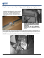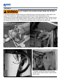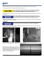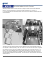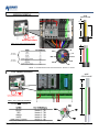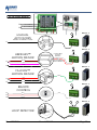
1
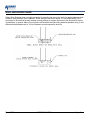
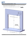
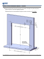
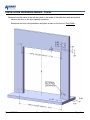
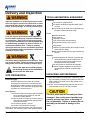
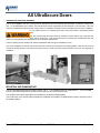
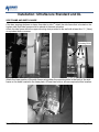
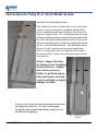
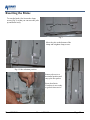
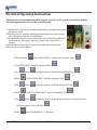
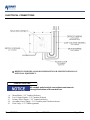
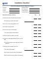
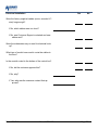
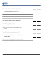
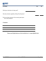
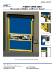
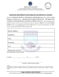
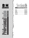
PN: 001450 Rev. 9/27/2010 Version 4.30 UltraSecure 3000 with UltraSmart INSTALLATION Doors are UltraRugged, UltraReliable, UltraAffordable. Albany Door Systems - A Company of Albany International Corp. All Rights Reserved 1080 Maritime Drive, Port Washington, WI 53074 - 975-A Old Norcross Road, Lawrenceville, Georgia 30046 262-268-9885 www.albanydoors.com INTRODUCTION The contents of this manual are designed to help you install UltraSecure 3000 high speed doors. DO NOT begin to install the high speed door unless you have read through the instructions in this manual. The safety alert symbol is used to identify safety information about hazards that can result in personal injury. A signal word (DANGER, WARNING, or CAUTION) is used with the safety alert symbol to indicate the likelihood and the potential severity of injury. In addition, a hazard symbol may be used to represent the type of hazard. DANGER indicates a hazard that, if not avoided, will result in death or serious injury. WARNING indicates a hazard that, if not avoided, could result in death or serious injury. CAUTION indicates a hazard that, if not avoided, might result in minor or moderate injury. CAUTION, when used without the alert symbol, indicates a situation that could result in damage to the door. NOTICE is used to inform you of a method, reference, or procedure that could assist with specific operations or procedures. Other symbols that may be used in this manual are: Lock Out / Tag Out Rev. 9/27/2010 Crushing Fire Manual #001450 Shock Read Manual Page 2 WALL ANCHORING GUIDE Albany Door Systems does not supply hardware for mounting the door to the wall. Use proper hardware best suited for each particular door installation. Some examples are shown below. It is the responsibility of the door owner to ensure that the wall material is strong enough to support the forces of the door and all anchoring hardware. In general, Albany Door Systems recommends through-bolting wherever possible using ½ inch diameter bolts/threaded-rods or 1/2 inch diameter concrete expansion anchors. Rev. 9/27/2010 Manual #001450 Page 3 INSTALLATION REFERENCE MARKS – 3000R Measure from the inside of the left door jamb to the inside of the right door jamb and place a mark on the floor on the door opening centerline. Reference the door’s documentation and place a mark on the floor at Door Width 2 Rev. 9/27/2010 Manual #001450 Page 4 INSTALLATION REFERENCE MARKS – 3000STD Measure from the inside of the left door jamb to the inside of the right door jamb and place a mark on the floor on the door opening centerline. Reference the door’s documentation and place a mark on the floor at Door Width 2 Rev. 9/27/2010 Manual #001450 Page 5 INSTALLATION REFERENCE MARKS – 3000XL Measure from the inside of the left door jamb to the inside of the right door jamb and place a mark on the floor on the door opening centerline. Reference the door’s documentation and place a mark on the floor at Door Width 2 Rev. 9/27/2010 Manual #001450 Page 6 Delivery and Inspection TOOLS AND MATERIALS REQUIRED Improper installation of anchoring devices or installation into aged or unsound concrete block, or other wall material may result in premature wear, product failure, property damage, or serious personal injury. Personnel Two people to install the door One person qualified to operate forklift, hoist, or crane Once electrician to install and connect the control panel and all electrical wiring Tools Assorted wrenches Tape measure Carpenter’s square Level (4ft minimum recommended) Lifting device (fork lift, hoist, crane) Lock-Out Tag-out all electrical power supplied to the door before making any electrical installations or connections. Also Lock-out Tag-out any equipment near the installation site if that equipment may be inadvertently operated into the area used to assemble and install the door. Failure to properly deenergize electrical circuits and disable equipment during installation and/or maintenance could result in death or serious injury. Use proper lifting equipment and techniques. Properly secure all loads. Failure to properly secure all lifting loads could result in death or serious injury. Secure the work area so that persons not working directly on the installation do not enter the work area. Materials Anchors appropriate for the type of wall the door and accessories are to be installed onto. Albany Door Systems recommends throughbolting doors whenever possible. Wire as specified on the electrical schematic Electrical supplies needed to comply with all regulating body electrical codes and standards. UNPACKING AND PREPARING SITE PREPARATION Electrical Supply Qualified electrician must make all electrical mountings and connections in accordance with all applicable regulating body(s) electrical codes and standards. The control box is equipped with a 3-phase AC fused disconnect. Door Opening 1.Are the door jambs and support wall structurally sound providing a flat surface for the side columns to mount against? 2.Check the width and height of the door opening and verify the measurements against the dimensions of the door. 3.Is the opening square? Plumb? 4.Is the floor level across the opening? Make all necessary structural repairs and improvements to provide a “yes” answer to each of the questions above. Rev. 9/27/2010 Lifting Straps 2 ladders or personnel lifts (tall enough to reach above the door head) Other tools as needed for the type of anchoring chosen 1.Inspect and unpack the components. Report any damage immediately to Albany Door Systems at 262-2689885. Refer to the serial number tag located on the door side frame. 2.DO NOT cut the banding which holds the door in a roll until instructed to do so in a later procedure. The door panel and roll assembly could be damaged. Use evenly spaced padded supports to prevent rips, tears, or bending of the roll assembly. Failure to protect the roll assembly could result in damage to the door. Manual #001450 Page 7 All UltraSecure Doors PREPARATION FOR DOOR ASSEMBLY Prior to door installation, the door opening must be examined to insure the existing wall construction is sufficient to support the door. For all UltraSecure Door versions, the side frames should be supported by a steel structure or concrete wall. If the door opening is insufficient to support the door a steel column or equivalent construction must be installed prior to the door installation. Do not install the doors on insulated panel walls, honeycomb bricks or lightweight partition walls. The door opening width and height must be checked to ensure that the door received is the same size as the opening. This can be achieved by comparing the manufactured door size listed in the corresponding door paperwork to the actual door measurements. The door opening must be closed to all vehicle or pedestrian traffic during the installation process. Prior to the installation the stretch wrap and/or shrink film needs to be removed from the shipping pallets. After this has occurred remove the springs and other loose door components from the inside of the side frames and place to the side. until required for installation. MOUNTING AND DISMOUNTING The top roll shipping pallet has two basic functions. The 1st. is as a shipping pallet or support & the 2 nd is as an installation aid. Use of the fork guides is required to insure that the door does not tip or slide. The complete side frames assemblies are located on/in a separate shipping pallet. The Control box, drive unit and other materials for installation are located in a cardboard box, which is located in one of the shipping pallets. Rev. 9/27/2010 Manual #001450 Page 8 Installation: UltraSecure Standard and XL SIDE FRAME AND WIDTH GAUGE If the door opening declines or slopes from side to side 1 st attach the side frame that is located on the highest side. Both side frames must be placed at the same elevation. Attach the side frame within the upper mounting slots provided to the wall with at least four ½” (12mm) or equivalent bolts or screws. Mounting Holes Attach the lower portion of the side frame using either the mounting slots in the back of the side frame or the holes located in the base plate. At least two bolts or screws required at this location. Rev. 9/27/2010 Manual #001450 Page 9 Place the second side frame on the wall and attach the width gauge to the two side frames. Using the same procedures as the first side frame attach the upper portion using the provided slots. Leave attachment screws loose until all side frame adjustments are made. Assemble lintel sealing profile before installing on the door. Use metal connector to join the profiles. Metal connector has a slotted hole used for wall anchoring. This bracket must be anchored. Double check door width by measuring between side frame black plastic wear strips. DO NOT USE THE LINTEL SEALING PROFILE TO SET THE WIDTH OF THE DOOR. Before attaching the lower portion of the side frame verify the door opening by measuring the distance between the black plastic wear guides. This measurement should be the same as the manufactured door size. After checking the measurement verify that the door is plumb in all directions. Attach the lower section using the same procedure as the first side frame. Rev. 9/27/2010 Manual #001450 Page 10 Side Frame Alignment for Light Curtains Run a mason’s line through the predrilled hole in the side frame to the same hole in the other frame. Next, measure the distance from the back of the frame to the mason’s line. Repeat this for the near and far side of the frame. The frame is properly aligned when the value for both measurements is the same. If the measurements are not the same, shim the rear of the frame on the side with the higher measured value. Repeat for both frames. Install light curtain using the pre-drilled holes. Space the light curtain off the frame using the supplied 3 fender washers with the mounting screws. The light curtain must be set so that the bottom of the light curtain is 2” off the floor. Be careful not to over tighten the screws as they can pull through the aluminium track of the light curtain. Tighten the width gauge screws. The width gauge serves as a cable duct for the stationary photocells and light curtain wires. Rev. 9/27/2010 Manual #001450 Page 11 TOP ROLL DO NOT REMOVE THE PACKING STRAPS FROM THE TOP ROLL First loosen the three screws attaching the bearing flange to the bearing plate on both sides of the barrel. This will allow for easier positioning of the roll into the side frame cradle cut out. Lift the top roll onto the side frames using a forklift, crane or other equivalent device. Position the top roll so that the center of the bearing flange is centered over the cradle cut out. Lower the roll so that the flange rests on the cradle. The two piece bearing flange sandwiches the side frame. 3000R ONLY. The drive unit must be installed on the top roll shaft prior to installing the top roll. Align the point of the mounting plate with the existing hole in the side frame. The picture at the left shows the standard and XL frame while the picture above shows the R frame. Rev. 9/27/2010 Manual #001450 Page 12 By hand, start all three of the M10 barrel fastening screws into the bearing plate. Next, tighten the bearing flange screws loosened earlier. Tighten the remaining 3 barrel fastening screws. Repeat the process on the other side. Once both sides are secure, the header lifting cradle can be cut away. When cutting away the cradle, be careful not to cut the barrel securing straps. These straps will keep the barrel wound until the gear motor assembly is installed. Cutting these straps will result in the barrel free falling. The barrel may begin to turn when the cradle is removed. However, the plastic straps will prevent the panel from unwinding and falling. If FULL ROLL COVERS were purchased, mount the motor-side full roll cover plate. Refer to the full roll cover assembly section for details. Failure to follow this step will result in lost time removing and re-installing the gear motor. Attach the mounting plate to the side frame with the provided M10 screws. Next tighten the three bearing flange bolts. Repeat this step for both sides of the door. GEARMOTOR This section applies only to the standard and XL version of the UltraSecure. Slide the drive unit onto the shaft of the top roll. Align the motor hollow shaft to the top roll shaft with the use of a 6mm hex key driven from below the fan guard. Connect the torque arm to the drive and side frame as shown. Rotate the barrel to align the bottom slat to the side frame funnel by pulling down on the brake release handle and rotating the barrel by hand. Release the brake. You are now ready to cut the barrel straps. Rev. 9/27/2010 Manual #001450 Page 13 This section applies only to the R version. Release the brake to allow the motor torque arm to swing to position over the motor attachment bracket. Screw the attachment bolt through the vibration dampener until it bottoms out. From underneath the motor attachment bracket, use the nut and lock washer to complete the motor bracket assembly. The picture to the right shows the chain connection between a drive sprocket and the counter balance belt take-up shaft. Depending on door size, some doors may have this chain driven counterbalance shaft on one side of the door and larger doors will require one on each side of the door. The tension of the chain is dependant upon the side frames being square to each other. If the chain is too loose or too tight then shimming or adjustment of the side frames may be required to provide the proper distance between the two sprockets. This chain does not have a tensioner and does not require a half link. Rev. 9/27/2010 Manual #001450 Page 14 COUNTERBALANCE This section applies only to the standard and XL version. Attach the counterbalance belts to the barrel under the metal bracket. Pre-wrap 2 turns of the belt in the opposite direction that the curtain will roll up. Run the counterbalancing belts behind the idler pullies and down the side frames. Please note that the belt must run flat against the pulley & free of any twisting. Rev. 9/27/2010 Manual #001450 Page 15 COUNTERBALANCE This section applies only to the R version. Connect barrel and belt shaft via roller chain. Clamp plate on belt shaft on top. Attach the counterbalance belts to the barrel under the metal bracket. Pre-wrap 2 turns of the belt in the opposite direction that the curtain will roll up. Secure the belt by tightening the clamp plate screws. Adjust the belt guide so that with the door open, the funnel edge is just off of the belt. Rev. 9/27/2010 Manual #001450 Page 16 Run the counterbalance belts through the upper spring attachment bracket. With the door in the open position add the appropriate pre stretch to the spring length and set the upper spring bracket at this location. DH <= 2000mm (78.75”) 2” of pre-stretch DH > 2000mm (78.75”) 6” of pre-stretch Hang the springs in the upper spring attachment brackets then stretch the springs down and attach to the lower brackets. Rev. 9/27/2010 Manual #001450 Page 17 Bottom Lift Strap Assembly Attach the lift belt to Adapter 4 by wrapping the lift belt under the adapter and passing the M5 x 20 screw through the front and back holes of the belt. The washer is placed on the front and the threaded belt clamp is positioned behind. Use the fender washers provided. Repeat for both sides. Rev. 9/27/2010 Manual #001450 Page 18 BRAKE RELEASE CABLE ROUTING Create a loop with 1 of 2 cable clamps supplied and hook the loop to the brake release handle spring. On the R model thread the inner cable thru the small hole in the belt guide plate and pull all the slack thru. On the Std and XL models the inner cable will thread thru the top support plate as shown and pull all the slack thru. Once the slack of the inner cable is pulled thru you will now thread on the outer sheath making sure to include the ferrules on both ends of the sheath. Now thread the inner cable down thru the brake release rod and pull the inner cable all the way thru until the outer sheath buts up to the brake release rod. Now loop the cable thru the grid on the fan shroud and pull all the slack thru. Tighten the cable clamp to retain the cable at this point. Proper operation of the brake release will allow for the outer sheath to push down on the brake release rod of the motor. Slight tension adjustments of the cable may be required. Once adjusted, cut the cable excess leaving 4 or more inches. Use caution when pulling the brake release so as not to allow the door curtain to travel out of the top of the guides. Rev. 9/27/2010 Manual #001450 Page 19 SIDE FRAME COVERS Install the cover gussets using the appropriate slots located in the side frame (Standard and XL configuration only). Attach the outer covers using the appropriate slots located in the side frame and the provided hardware. It may be necessary to push the cover toward the door blade to start the screws. Use care not to cross thread the compression nut inserts. It is critical to have a smooth transition between the upper and lower plastic rails. The gap between the plastic rails & the curtain should be approximately 0.04” (1mm). The R model The XL model has an additional outer cover that has does not have slotted holes in the bolting flange which allows for an inner cover the gap adjustment to be made as shown below. gusset as above. It only has a one piece outer cover. The bolting flange of the cover has slotted holes to allow for cover adjustment. There is also a reinforcement gusset at the top of the cover that will need to be bolted in place as well. Use care not to cross thread the compression nut inserts. High impact tools are not recommended for installing these bolts. Rev. 9/27/2010 Manual #001450 Page 20 Install the side frame spring box covers with the provided hardware. Front mounted light curtains (if applicable) Mount light curtains to the bracket on the side frame using two M4 screws supplied with the light curtains. Plug the light curtain cable into the supplied M12 cable. Rev. 9/27/2010 Manual #001450 Page 21 FULL ROLL AND MOTOR COVERS These instructions pertain to the Standard and XL versions only. Install the side cover (1) assembly before mounting the drive unit. After the remaining installation is completed install the front cover (3) and the top cover (4) with the provided hardware. Rev. 9/27/2010 Manual #001450 Page 22 Using the hardware provided install the motor cover back to the side plate (1). Next install the bottom cover (2), then the front cover (3), and finish by installing the top cover (4). These instructions pertain to the 3000R version only. Install the support plates of the top roll cover at the side frames. Next attach the front cover followed by the top cover. Install the motor cover. Rev. 9/27/2010 Manual #001450 Page 23 Instructions for Using Over-Travel Brake System. About the Over-Travel Brake System Your UltraSecure door is fitted with an over-travel brake system to stop your door in a controlled manner in the event a condition should arise leading to the door traveling past its upper limits. The system terminates the open command and immediately engages the gear motor brake. But, due to the high rotational inertia of the barrel, an additional mechanical brake is utilized, catching the bottom slat for a controlled deceleration. This addendum shows how to reset the system to get your door operational. Prior to resetting the brake, you must lower the door to the open position. Follow electrical instructions for lowering process. Notice: Inspect the door for damage prior to putting it back in service. Repair door where necessary. Failure to perform inspections and repairs can lead to personal injury, property damage or death. If an over-travel event occurs, hooks mounted on the bottom slat engage the brake yoke. The yoke is then dragged through the pair of brake clamps finally coming to rest at the end of the clamp (fig 2.). Fig 2. Safety brake deployed. Rev. 9/27/2010 Manual #001450 Page 24 Resetting the Brake To reset the brake, first loosen the clamp screws (Fig 3) so that you can move the yoke up and down easily. Clamp Screws Fig 3. Move the yoke to the bottom of the clamp and retighten clamp screws. Fig 4. Yoke at bottom position. Rotate yoke rest to a horizontal position and snap yoke into pocket. Reset door limits. Your door is now ready to go back into service. Rev. 9/27/2010 Manual #001450 Page 25 Electrical Operation Instructions When the over-travel mechanism has been engaged, the power to the control system will be disabled. The following procedure will reset the electrical system: 1.Turn the power off (wait 20 seconds) and then back on using the main panel disconnect switch. 2.With the power on, open the control panel and locate the over-travel sensor relay (shown here with teal override button). 3.Press and hold the teal override switch on the sensor relay and jog the door down using the “Emergency Jog Down” button on the face of the CModule. 4.Once the door has been lowered below the normal open position, stop. 5.Reset the door limits as follows: 1)Press and hold until “LIMIT SETUP” is shown on the display; Press 2)“CLOSED LIMIT” should be displayed; Press 3)Use 4)Press 5)Use 6)Press 7)Use and/or to bring the door to the full closed position; Press “FULL OPEN LIMIT” should be displayed; Press and/or to bring the door to the full open position; Press “PARTIAL OPEN LIMIT” should be displayed; Press and/or to bring the door to the partial open position or set the same as the full open position if not used; Press 8)Press until “DOOR READY” is displayed Rev. 9/27/2010 Manual #001450 Page 26 ELECTRICAL CONNECTIONS REFER TO INDIVIDUAL DOOR SCHEMATICS FOR SPECIFIC DETAILS ON OPTIONAL EQUIPMENT.. CONDUIT ROUTING All conduit and electrical connections must come in through the bottom of the control box. -A-B-C-D-E- Motor/Brake—3/4” Conduit (all doors) Low Voltage Signals—3/4” Conduit (all doors) Primary Power Supply—3/4” Conduit (all doors) Secondary Power Supply—3/4” Conduit (some UltraFreeze doors) Floor Loop—1/2” Conduit (optional) Rev. 9/27/2010 Manual #001450 Page 27 MOTOR WIRING WIRE STRIP GAUGE ¼” 8" 6" ¾” MOTOR WIRE CONDUIT BRAKE WIRES DRILL ONLY INTO BOTTOM OF BOX USE MINIMUM ¾” CONDUIT ¼” T2 MG T1 SEPARATE FOIL SHIELD MG SEPARATE FOIL SHIELD 6" T3 B1 MG B2 NOTE: MOTOR WIRES TO CHANGE DIRECTION OF MOTOR ROTATION – SWITCH T1 AND T2 ENCODER WIRING WIRE STRIP GAUGE ¼” ¾” LOW VOLTAGE CONDUIT ENCODER, SAFETY, ACTIVATION 4" DRILL ONLY INTO BOTTOM OF BOX USE MINIMUM ¾” CONDUIT TB2 TB3 TB1 TB1 TB4 Rev. 9/27/2010 Manual #001450 Page 28 ACTIVATION WIRING N TOP 3 TERMINALS H NEXT 5 TERMINALS MANUAL ACTIVATORS MODULE - A TB2 1 2 3 4 CONNECT AS “NORMALLY OPEN” 5 6 H MODULE - A TB3 HERKULES™ MOTION SENSOR H BROWN GREEN N WHITE Connect GRAY for Person Detection 1 2 3 4 5 6 GRAY RED Connect RED for Vehicle Detection PINK MODULE - A TB3 FALCON™ MOTION SENSOR 1 2 3 4 5 6 GREEN RED H WHITE N BLACK REMOTE CONTROL H H N MODULE - A TB2 1 GRAY 2 3 4 5 6 GRAY RED BLACK TB3 1 2 TB4 3 4 5 MODULE - D 6 LOOP DETECTOR (optional) Rev. 9/27/2010 Manual #001450 Page 29 Rev. 9/27/2010 Manual #001450 Page 30 Rev. 9/27/2010 Manual #001450 Page 31 Rev. 9/27/2010 Manual #001450 Page 32 Rev. 9/27/2010 Manual #001450 Page 33 ENABLING THE WIRELESS SAFETY SYSTEM If the door is equipped with Albany’s Wireless Safety System (indicated by the lack of a coil cord), the following steps must be taken to initialize the communications: 1. 2. 3. 4. Locate the RF transceiver on the bottom slat (shown to left) Remove the cover and locate the RFID number on the pull strip. Setup the UltraSmart™ Controller according to the procedure below. Once the RF ID is set per the instructions below, turn off the power to the control and after 10 seconds hold the circuit board with one hand and pull out the strip. Turn the power back on and the RF should complete the communication link shortly with a display of Door Ready. 5. Replace the cover and 4 screws. 6. Test the system. UltraSmart™ Controller Settings for Inputting the RF ID Press and hold until “LIMIT SETUP” is shown on the display Press until “WIRELESS SETUP” is shown; Press Press until “BOTTOM BAR ID” is shown; Press Change the number to the RFID number on the bottom bar label using Press to store the value and press and until “DOOR READY” is displayed Thoroughly test the system to determine if all sensors/switches are functioning properly. Make sure you can answer “yes” to the following questions: Does the door reverse when the reversing edge is tripped upon closing? Does the UltraSmart™ controller recognize the left-side breakaway switch? Does the UltraSmart™ controller recognize the right-side breakaway switch? If you cannot answer “yes” to all the above questions, check all wiring connections and ensure the RFID is set to the same number that is labeled on the wireless bottom bar module. Rev. 9/27/2010 Manual #001450 Page 34 UltraSmart™ STARTUP PROCEDURE Albany’s UltraSmart™ control system is designed to accommodate numerous option modules and future technological advances. This manual will address necessary settings for the standard options; however, optional modules and special applications may require additional steps to be taken for proper setup. Refer to the control schematic shipped inside the panel enclosure for additional electrical and setup details. SETTING DOOR LIMITS NOTE: SAFETY DEVICES WILL PREVENT THE DOOR FROM CLOSING IF ACTIVATED DURING SETUP ENABLE THE WIRELESS SYSTEM (IF EQUIPPED) PRIOR TO SETTING DOOR LIMITS 1)Press and hold until “LIMIT SETUP” is shown on the display; Press 2)“CLOSED LIMIT” should be displayed; Press 3)Use 4)Press 5)Use 6)Press 7)Use and/or to bring the door to the full closed position; Press “FULL OPEN LIMIT” should be displayed; Press and/or to bring the door to the full open position; Press “PARTIAL OPEN LIMIT” should be displayed; Press and/or to bring the door to the partial open position or set the same as the full open position if not used; Press 8)Press Rev. 9/27/2010 until “DOOR READY” is displayed Manual #001450 Page 35 Rev. 9/27/2010 Manual #001450 Page 36 Installation Checklist Please fill out below and return to Albany Door Systems Customer Installation Date(s): Location: Door Serial #(s): Contact: Contact Phone #: Install Company: Contact & Phone #: Mechanical Installation (All Doors) Yes No Is the door secured to the wall using thru-bolts? If No, what type of anchor was used? Are the door roll and rear spreader level? Are the side columns plumb? Does the door have counterweights? If Yes, are the straps routed properly? Is the door caulked or sealed to the wall? Are there any visible gaps between the door and the wall? If No, did the customer contact approve of door to wall seal? Is there any visible damage to the door? If Yes, what is the damage? Was Customer Service notified of the damage? Was the customer contact notified ofManual the damage? Rev. 9/27/2010 #001450 Page 37 Electrical Installation Yes No Were the factory supplied cables (motor, encoder & 7wire) long enough? If No, which cables were too short? If No, was Customer Support contacted and new cables sent? Were the schematics easy to read for electrical hookup? What type of conduit was used to route the cables to the door? Is the conduit routed to the bottom of the control box? If No, did the customer approve this? If No, why? If Yes, who was the customer contact that approved? Rev. 9/27/2010 Manual #001450 Page 38 Door Start-Up Yes No Was the door start-up procedure easy to follow? If No, what problem(s) did you run into? Was Customer Support notified of these issues? Is the Reversing Edge working? Are the front and rear light curtains (or photo-eyes) working? Do the bottom bar breakaway switches work? Does the door’s self-repair feature work when the door is broken away? If the door has counterweights, does the egress work? Rev. 9/27/2010 Manual #001450 Page 39 Activation Yes No What type of activation is being used? Was the activation supplied by Albany Door Systems? Did the customer approve of the mounting and operation of the activators? Comments Please email digital pictures of the installed door to: [email protected] Rev. 9/27/2010 Manual #001450 Page 40