1
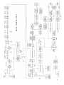
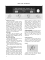
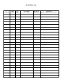
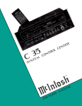
FM STEREO
TUNER
MR 71
TABLE OF CONTENTS
CONTENTS
INTRODUCTION
1
TECHNICAL DESCRIPTION
2
FRONT PANEL INFORMATION
6
BACK PANEL INFORMATION
8
INSTALLATION
8
CONNECTING
Audio Outputs
Stereophonic FM Multiplex
Monophonic FM
Remote Amplifiers
Off-The-Air Recording
Antenna Connections
9
9
9
9
9
9
9
OPERATING INSTRUCTIONS
Stereophonic FM Multiplex
Monophonic FM
11
11
11
ADJUSTMENTS
Muting Threshold
Dial Panel Lights
Output Adjust
12
12
12
12
GUARANTEE
13
OWNER'S MANUAL
MR71
THANK YOU
Judging from the stereo equipment you own, you rank high
among discriminating music listeners. You are probably no
freshman when it comes to stereo. Never-the-less we ask you
to read and carefully follow these instructions to insure a
successful partnership between you and your new stereo
equipment.
You now have "THE BEST." Used properly you are in for
thousands of hours of musical enjoyment.
If you are in a hurry, read page 3 first. This gives you a brief
outline of what each control and indicator does. Reading time
for this manual is 30 minutes. This is time well spent.
MR 71 FM STEREO TUNER
INTRODUCTION
The Mclntosh MR 71 is a precision engineered, highly sensitive FM Multiplex Tuner.
The research staff of Mclntosh Laboratory
has developed five new tuner circuit improvements for the MR 71.
1. Automatic stereo-mono switching that
is "clickless" and completely electronic.
(Patent applied for.)
2. Multipath indicator to eliminate multipath reception by showing when your antenna is rotated to the correct position for minimum multipath distortion.
3. Double tuned input circuits before the
first R.F. amplifier to reduce spurious responses.
4. New D'Arsonval movement meters of
increased sensitivity which do not need zero
setting adjustments.
5. A new computer designed filter to reduce noise from stations broadcasting subcarrier auxiliary music services. No other
tuner uses such a filter.
The MR 71 also uses the exclusive Mclntosh PANLOC method of installation. The
PANLOC system gives you absolute ease of
installation, operation, and maintenance.
PANLOC is the first professional installation
technique to be used on stereo instruments.
In the PANLOC system a metal shelf is
mounted first. The tuner slides into position
on this shelf. Depressing the PANLOC buttons on the front panel locks the tuner firmly
into place for normal operation. To unlock
the tuner depress the PANLOC buttons a
second time. The tuner can now slide from
the front panel. The tuner will lock into this
position, preventing accidental release of
the tuner from the installation. Depressing
the holding latches allows the tuner to be
taken out of the PANLOC shelf or to slide
back into position against the mounting panel.
The finest possible reception of FM monophonic and FM multiplex stereophonic broadcasts is assured by the Mclntosh MR 71
tuner.
Once you have enjoyed the outstanding
performance of the MR 71, you will understand why Mclntosh products have earned
their reputation as "THE BEST." Your Mclntosh MR 71 tuner will give you years of the
finest possible FM reception, and will be a
valued part of your home music system.
1
TECHNICAL DESCRIPTION
The MR 71 tuner has a 6DS4 high-grain
Nuvistor for the first RF amplifier. The Nuvistor (triode) operates into a second triode tube
to form a cascade amplifier. Careful design
of the operating characteristics allows the
cascade amplifier to handle a wide dynamic
range of signals with excellent signal-tonoise ratio.
A double-tuned RF input circuit combined
with the Nuvistor-tube cascade amplifier
reduces spurious signals to an extremely low
value. Sensitivity is increased to the highest
possible rating, while still retaining high
selectivity.
A newly developed Automatic Frequency
Control (AFC) circuit greatly simplifies tuning.
As the tuning knob is moved, the AFC circuit
automatically cuts off for sharpest tuning.
After the station is tuned in, the AFC circuit
gradually comes into operation over a 3
second interval. The AFC action automatically
brings the tuning to minimum distortion. This
automatic tuning repeats its action each
time the tuning dial is moved to a new station. The amount of AFC action is fully adjustable with a front panel control.
The AFC circuit is unique. It uses a silicon
diode in place of a conventional tube. The
silicon diode improves the overall AFC performance. It is unaffected by temperature
changes. It has no warm-up drift and eliminates the chance of tube filament hum. A
temperature-compensated narrow band detector supplies operating signals to the AFC
circuit. This insures positive AFC action. The
narrow band detector also operates the FM
tuning meter amplifier and the ultrasonic
muting circuit.
The Mclntosh developed ultrasonic muting
circuit automatically suppresses all interstation noise, including the noises usually heard
tuning in and out of a station. Weak or distant
stations that can't override the background
noise and interference are suppressed by the
muting. A front panel switch allows muting to
be cut off for listening to weak and noisy
stations. A back panel adjust control is factory set to the correct muting threshold level.
2
The mixer output is amplified through five
intermediate frequency stages with flattopped highly selective response curves.
The IF transformers have wide band response with maximum adjacent channel
rejection. Construction of the IF transformers
assures electrical stability and resistance to
mechanical shock and vibration. More than
adequate gain is provided to operate both
limiters on the weakest signals. Two complete limiters are used for the best possible
signal-to-noise ratio.
A separate wide band detector handles
only audio frequencies for low distortion and
wide frequency response.
Both the RF and IF circuits are completely
shielded in excess of FCC requirements for
suppression of radiation of the FM oscillator
and IF frequencies.
The MR 71 multiplex decoder uses a
Mclntosh developed detector. The advantage
of this circuit is the elimination of critical
adjustments necessary with commonly used
multiplex matrixing methods. The L-R (left
minus right) stereo sidebands are detected.
Then automatically combined with the L+R
main carrier signal. The left and right channel signals are then produced with excellent
separation.
A temperature stabilized 19KC amplifier
locks in a highly stable 38KC synchronous
oscillator. This method gives exceptional
noise immunity. Balanced detectors cancel
the 38KC signal components in the output,
providing low distortion and reduced susceptibility to spurious signals. Tape recording interference is minimized by this method.
A highly selective computer designed filter
reduces noise from stations broadcasting
auxiliary music services. The filter reduces
the frequency band from 63-74KC approximately 50db. The filter response slope is
275db per octave. The noise is eliminated
without affecting normal program material.
The MR 71 has a multiplex stereo indicator
which lights when the dial pointer crosses a
station broadcasting multiplex stereo. A
unique circuit using a transistor operates the
Your Mclntosh MR71 tuner will give you many years of pleasant
and satisfactory performance. If you have any questions concerning the operation or maintenance of this tuner please contact:
Customer Service
Mclntosh Laboratory Inc.
2 Chambers Street
Binghamton, New York
Our telephone number is 723-5491.
The direct dial area code is 607.
GUARANTEE
Mclntosh Laboratory Incorporated guarantees this equipment to perform as advertised. We also guarantee the mechanical and
electrical workmanship and components of
this equipment to be free of defects for a
period of 90 days from date of purchase,
This guarantee does not extend to components damaged by improper use nor does it
extend to damage incurred during transportation to and from Mclntosh Laboratory, Inc.
3-YEAR FACTORY SERVICE CONTRACT
An application for a FREE 3-YEAR FACTORY SERVICE CONTRACT is included in the
pocket in the back cover of this manual. The
FREE 3-YEAR FACTORY SERVICE CONTRACT
will be issued by Mclntosh Laboratory upon
receipt of the completely filed out application form. The term of this contract is de-
fined in the 3-year factory service contract.
If the application is not mailed to Mclntosh
Laboratory, only the services offered under
the standard 90-day guarantee will apply on
this equipment. TAKE ADVANTAGE OF 3
YEARS OF FREE FACTORY SERVICE BY
FILLING IN THE APPLICATION NOW.
Design subject to change without notice.
13
MPX stereo indicator lamp. The transistor is
controlled by a noise-rejecting differential
detecting bridge circuit. The circuit discriminates between noise and the 19KC multiplex
pilot signal. The indicator will light only on
the 19KC signal present in a multiplex stereo
broadcast.
The MR 71 uses a new Mclntosh developed
automatic mono-stereo switching circuit.
(Pat. Pend.) The switching is electronic without switching clicks or transients.
The circuit switches smoothly and silently
when the 19KC multiplex carrier is present.
The multipath signal indicator on the tuning dial is an electron ray tube. This is an
exclusive Mclntosh development. Multipath
signal reception causes moderate to severe
distortion and poor stereo channel separation. By knowing the presence of multipath
reception, a directional FM antenna may be
rotated to reduce or eliminate the multipath
signal. The MR 71 multipath indicator shows
if there are multipath signals present by
rapid fluctuation of the electron ray beams.
With the antenna correctly positioned, the
indicator beams remain relatively steady,
showing that multipath distortion has been
eliminated.
Two pairs of audio output jacks are on the
back panel. One pair of jacks is controlled
only by the front panel volume control. The
other pair of jacks is controlled only by the
back panel output adjust controls. Two stage
feedback type preamplifiers on both channels provide low impedance outputs. More
than sufficient output volume is available to
feed power amplifiers as well as preamplifiers.
A new type of mechanical tuning assembly
gives the MR 71 extremely smooth flywheel
tuning action. The tuning capacitor is driven
directly, and in turn drives the pointer. Backlash is eliminated with this design. A teflon
lined pointer carriage and nylon pulleys reduce friction and wear to give an unusually
smooth and quiet dial action.
IF YOU ARE IN A HURRY
Turn antenna so the eye is steady.
Adjust to desired volume.
Tune for Max. reading.
Power off. Use stereo-auto
position: will switch
automatically from stereo to mono.
Will light only on stations
broadcasting MPX stereo,
Tuning . . . select
desired station
Tune for center of black area.
In . . . eliminates interstation
noise. Out . . . use to receive
weak stations.
Continuously variable, use
Max. position for MPX reception.
3
SPECIFICATIONS
Useable Sensitivity
2.5 microvolts at 100% modulation (±75KC
deviation) for less than 3% total noise and
harmonic distortion in accordance with
IHF standards.
Audio Frequency Response
Within ½db from 20 to 20,000 cycles.
Distortion
Lessthan0.5%at 100% modulation ±75KC
deviation
Capture Ratio
1.5db at 100% modulation.
Muting
IF injected ultrasonic muting: at least 60db
noise reduction between stations.
Oscillator Drift
Less than 25KC with AFC disabled; negligible with AFC in operation.
Image Rejection
Better than 80db at 90MC; better than
70db at 105MC.
Hum
Better than 70db below 100% modulation.
Output
Approximately 2.5 volts; low impedance.
Antenna Inputs
300 ohms balanced; 75 ohms unbalanced.
RF Amplifier
Cascode with 6DS4 Nuvistor in first stage.
IF Stages
Five, with 200KC bandwidth, flat top
response.
Limiters
Two.
Radiation
Substantially below FCC requirements.
Multiplex Channel Separation
Better than 30db at 1000 cycles.
Multiplex Filter
Greater than 48db suppression of 19KC
pilot and 38KC carrier.
Multiplex Indicator
Front panel multiplex stereo light activated
by 19KC carrier-only.
Multiplex Type
Peak-detecting, self matrixing detector.
SCA Filter
50db down at 67KC to 74KC 275db per
octave slope.
4
Automatic Mono-Stereo Switch
An exclusive Mclntosh development; allelectronic automatic mono-stereo switching circuit. (Pat. Pend.).
Tube and Semiconductor Complement
1-6DS4 Nuvistor, 1st RF.
1-12AT7, 2nd RF and Mixer.
1-6BN4A, Oscillator.
1-6AU6, 1st IF.
1-6AU6, 2nd IF.
1-6AU6, 3rd IF.
1-6AU6, 4th IF and 1st Limiter.
1-6CS6, 5th IF 2nd Limiter and Muting.
1—6BN8, Muting Amplifier, Muting
Detector, AVC Clamper.
2-6BL8, Left and Right, 1st and 2nd
Audio Amplifiers.
1-6U8, MPX Amplifier, MPX Indicator
Control.
1-6HU6/EM87 Multipath Indicator.
1-12AU7, MPX Oscillator.
1-ST2-275, Voltage Reference.
1-MA113 (Transistor), MPX Indicator
Lamp Switch.
2-1N542 Diodes, Wide Band
Discriminator.
2—1N542 Diodes, Narrow Band
Discriminator.
4-1N542 Diodes, Balanced MPX
Detector.
2-1N542 Diodes, Balanced Detector for
MPX Indicator.
2—Selenium Rectifiers, High Voltage
Power Supply.
1-No. 1850 Lamp, MPX Indicator.
Power Consumption
70 watts, 105 to 125 volts, 50 to 60 cycles.
Dimensions
Front Panel; 16 inches wide by 57/16 inches
high; chassis (including PANLOC shelf) 15
inches wide by 5 inches high by 13 inches
deep, including connectors; clearance in
front of mounting panel including knobs.
1½ inches.
Weight
Chassis only, 27 pounds.
In shipping carton, 37 pounds.
5
BLOCK DIAGRAM MR 71
FRONT PANEL INFORMATION
TUNING DIAL SCALES
The MR 71 has two dial scales, the 88 to
108 scale marked in megacycles and the
0-100 logging scale. The dial scale marked
in megacycles indicates the positions of FM
stations in the 88 to 108 megacycle band.
The logging scale with linear divisions from
0-100 is located directly beneath the 88 to
108 scale. The logging scale can be used to
accurately retune any station. You may find
it easier to keep a record of your favorite
stations by use of the logging scale.
INDICATORS
The MR 71 has four indicators on the
dial panel: MULTIPATH indicator, SIGNAL
STRENGTH indicator, STEREO indicator, and
the TUNING indicator.
MULTIPATH INDICATOR
The MR 71 MULTIPATH indicator is an exclusive Mclntosh development.
The MR 71 MULTIPATH indicator makes it
possible to improve FM reception with
precise FM antenna positioning.
Reduce noise due to multipath reception.
Reduce distortion due to multipath reception.
Improve stereo separation and the accuracy of your STEREO INDICATOR by reducing
multipath reception.
The MR 71 MULTIPATH INDICATOR shows
distortion from multipath signal reception.
Multipath reception causes the two beams on
the indicator to fluctuate rapidly. When the
antenna is rotated to the correct position,
the indicator beams will remain steady. The
6
directional antenna is picking up only the
desired signal and rejecting the reflected
multipath signals. In some locations, it is
possible that the best reception will occur on
a strong reflected signal rather than the
direct signal. When you tune to a different
station, the multipath indicator will tell you
if multipath is present. Multipath is independent of signal strength.
STEREO
INDICATOR
The stereo indicator will light when the dial
pointer crosses a station broadcasting multiplex stereo. The special circuit used will light
ONLY on the 19KC multiplex carrier. The
indicator will not light on noise pulses or
interference.
TUNING INDICATOR
An FM station is correctly tuned when the
indicator is in the black area of the tuning
indicator. The action of the TUNING indicator
is independent of station signal strength.
VOLUME
Controls volume level when the tuner is
connected to the pair of jacks marked
FRONT PANEL CONTROLLED.
MODE SELECTOR
POWER OFF
brings the tuning to minimum distortion. The
AFC action repeats itself each time the tuning
dial is moved to a different station.
The amount of AFC action is adjustable
with the AUTO FREQ. CONTROL. Full left
(MIN) position of the control cuts off AFC
action. Full right (MAX) position gives maximum AFC action.
MONO
Normally, the best tuning occurs with the
AUTO FREQ. CONTROL set at or near MAX
position. If several stations are very close
together on the dial, or if a desired station is
very close to a much stronger station, a lower
AFC setting is usually needed for best tuning.
Provides monophonic FM at both pairs of
left and right channel audio output jacks.
MUTING
Turns off the tuner AC power and the AC
outlet on the tuner back panel.
STEREO AUTO
The STEREO AUTO position provides both
monophonic FM and FM multiplex stereo at
the left and right channel audio output jacks.
Assume you have the MR 71 MODE SELECTOR in the STEREO AUTO position. You are
listening to a station broadcasting FM monophonic. The station switches to MPX stereo
broadcast. The MULTIPLEX indicator will
light. The MR 71 will automatically switch to
FM multiplex stereo operation. If mono
broadcasting is resumed the MR 71 will
automatically switch to FM monophonic.
AUTO FREQ. CONTROL
OUT
OUT—This position turns off the muting to
allow conventional tuning with interstation
noise present. Use this setting to listen to
weak or distant stations that have noise or
interference.
IN—This position turns on the muting circuit. Muting suppresses all background hiss
and noise usually heard when tuning between stations. Weak or distant stations that
cannot override the background noise and
interference are suppressed by the muting.
PANLOC BUTTONS
The Automatic Frequency Control (AFC)
circuit makes FM tuning easier. It eliminates
the possibility of tuner drift. The AFC circuit
in the MR 71 is electronically delayed in its
action. This is an exclusive Mclntosh development. When the tuning dial is moved, the
AFC circuit is temporarily cut off. When the
dial pointer comes to rest on a station the
AFC gradually comes into operation. This
takes three seconds. The AFC automatically
At the bottom of the front corners are the
PANLOC buttons. After a tuner is installed on
the PANLOC shelf, depressing the PANLOC
buttons will lock the tuner firmly in position.
Depressing the PANLOC buttons a second
time (as with a ball-point pen> will release the
tuner. The tuner can then be slid forward to
the inspection and adjustment position. The
PANLOC system gives you absolute ease of
installation, operation and maintenance.
7
BACK PANEL INFORMATION
TP 2
fier which has its own master volume control.
Test point TP 2 is provided for tuner circuit
alignment. It is also used in conjunction with
the Mclntosh Ml 2 or Ml 3.
The right hand pair of AUDIO OUTPUT
jacks provides audio signal controlled by the
MR 71 front panel VOLUME control. Use
these output jacks to connect to external
power amplifier, tape recorders, or any
equipment which requires continuous front
panel control of tuner output volume.
OUTPUT ADJ
This dual concentric control adjusts the
output volume levels at the left-hand pair of
AUDIO OUTPUT JACKS. The center shaft
adjusts the LEFT channel output, and the
outer sleeve adjusts the RIGHT channel output. These output control settings for the left
pair of jacks are not affected by the MR 71
front panel volume control.
MUTING ADJ
Adjust the operating threshold of the ultrasonic muting circuit.
AUDIO OUTPUT-LEFT-RIGHT
The left-hand pair of AUDIO OUTPUT jacks
provides audio signals unaffected by the
MR 71 front panel VOLUME control. The dual
concentric OUTPUT ADJUST controls set the
volume levels. Use these output jacks to connect the tuner to a stereo control preampli-
300 OHM-75 OHM ANTENNA
Terminal for connecting FM antennas to
the MR 71.
1A SLO BLO FUSE
A 1 amp "Slo-Blo" fuse protects the tuner
circuits. This fuse does not protect additional
equipment connected to the back panel AC
outlet.
AC OUTLET
Provides 117 volt AC power up to 350 watts
maximum for additional equipment such as
turntables, or other tuners. This outlet is not
fused. It turns on and off with the front panel
MODE SELECTOR switch.
PANEL LIGHT SWITCH
Adjusts the panel lights to bright or dim.
INSTALLATION
The Mclntosh MR 71 tuner may be installed on a table, on a shelf, in a custom
built-in cabinet, or in a professional equipment rack. For best appearance in an open
installation, mount the MR 71 in the attractive Mclntosh L11 cabinet. The L12 is oiled
walnut. The L11 is lacquered walnut.
The MR 71 tuner is installed by the new
exclusive Mclntosh PANLOC method. Refer
to the special PANLOC SYSTEM INSTALLATION instructions included with your MR 71.
8
Allow at least 13¾ inches behind the mounting panel for the MR 71 chassis. This includes clearance for leads and connectors.
Allow inside dimensions of at least 16½
inches in width and 6 inches in height for
adequate air circulation. The back of the
MR 71 cabinet should be as open as possible
for the best ventilation. Avoid mounting the
tuner directly over a power amplifier. The
heat from the amplifier may change the
precision tuner calibration. Adequate ventilation will give your tuner long trouble-free life.
CONNECTING
AUDIO OUTPUTS
Use the FIXED OUTPUT jacks (left-hand
pair of jacks next to OUTPUT ADJ) to connect
to a conventional control preamplifier which
has its own volume control. Full tuner output
is available at all times from the FIXED
OUTPUT jacks.
Use the FRONT PANEL CONTROLLED jacks
to connect to a conventional control preamplifier when continuous front panel control of tuner volume is desired. These jacks
may be used to connect to external equipment such as power amplifiers or tape
recorders where control of tuner volume is
necessary. There is no difference in the
signal quality or output levels available at
each pair of output jacks.
STEREOPHONIC FM
MULTIPLEX
Connect a shielded cable from the tuner
LEFT channel AUDIO OUTPUT jack to the
control preamplifier LEFT channel tuner or
auxiliary input jack.
Connect a second shielded cable from the
RIGHT channel tuner AUDIO output jack to
the control preamplifier RIGHT channel
tuner or auxiliary input jack. When the MR 71
mode selector is set to MONO or STEREO
AUTO position, a monophonic broadcast will
automatically be present at both left and
right outputs. For a stereo broadcast set the
MODE SELECTOR in the STEREO AUTO
position.
gram can then be fed to speaker systems
apart from the main sound system.
OFF THE AIR RECORDING
Tape recorders or tape decks with recordplayback preamplifiers are normally connected to the Tape Output jacks on the control preamplifier. Any FM program coming
through the tuner into the preamplifier can
be recorded on tape. You may also connect
the extra pair of tuner audio output jacks
directly to the recorder inputs if desired.
ANTENNA CONNECTIONS
Satisfactory FM multiplex stereo reception
requires 10 times as much signal as FM
monophonic reception. Monophonic installations that were satisfactory with an indoor
FM antenna may require an outside or directional FM antenna for satisfactory multiplex
stereo reception. A good directional antenna
with a rotator makes it possible to eliminate
or minimize multipath distortion. The MR 71
multipath indicator shows the correct antenna position for reception with minimum
multipath distortion.
INDOOR FLEXIBLE FM DIPOLE
MONOPHONIC FM
The MR 71 can be used strictly for monophonic reception.
Connect a shielded cable from either the
left or right audio output jack to the monophonic control preamplifier auxiliary or tuner
input jack. With the MR 71 MODE SELECTOR
set to MONO, the monophonic FM signal
appears at both the left and right channel
AUDIO OUTPUT jacks.
REMOTE AMPLIFIERS
The pair of audio output jacks not being
used in an installation may be connected to
external or remote amplifiers. An FM pro-
A convenient flexible indoor FM dipole
(300 ohm) antenna is supplied with the
MR 71 tuner. This antenna is easy to install.
It is suitable for a good FM reception in high
signal areas.
Connect the two leads of the dipole antenna to the two terminals marked 300
OHM on the MR 71 back panel.
The flexibility of the thin flat wire allows the
dipole to be easily located behind the equipment enclosure or any position near the
tuner. Open the dipole into a "T." Extend the
SEE DIAGRAM NEXT PAGE
9
10
arms as straight as possible. The dipole
antenna is somewhat directional. It should be
positioned for best reception of the desired
stations.
Experimenting with the dipole position may
be necessary to reduce multipath distortion
on certain stations. Since it is not convenient
to continually change the position of the
dipole, you may have to set it for minimum
multipath on your favorite station.
An outdoor FM antenna is recommended
for best FM reception under all conditions.
In fringe areas, a highly directional FM antenna used with a rotator will give the finest
possible FM reception. Rotate the antenna
until it points in the direction of the station or
until it receives the best possible signal. Use
the multipath, signal strength and tuning
indicators to position the antenna correctly.
75 OHM ANTENNA
IMPORTANT
Keep the dipole away from large
metal objects or surfaces. They interfere with the efficiency of the antenna.
OUTDOOR FM ANTENNA
An unbalanced 75 ohm FM antenna can be
used with the MR 71. A BNC connector is
provided. Connect a Male BNC connector
to the female BNC connector on the rear
panel of the MR 71.
OPERATING INSTRUCTIONS
STEREOPHONIC FM MULTIPLEX
MONOPHONIC FM
1. Turn the MODE SELECTOR to STEREO
AUTO.
1. Turn the MODE SELECTOR to MONO to
listen only to monophonic FM.
2. Turn MUTING to IN.
3.Turn the FM TUNING dial to the desired
station.
The TUNING indicator pointer should be in
the black area of the tuning indicator meter.
When the MPX STEREO indicator is lit, the
station is broadcasting a 19KC carrier for
multiplex stereo. The MR 71 will automatically switch to stereo Mode. If a station is
broadcasting monophonic FM program, the
MPX STEREO indicator will remain off and
the tuner will automatically switch to Mono
Mode.
4. Adjust the volume control to desired
listening level.
If the fixed audio output jacks are used, the
tuner volume control will not affect volume.
Note: If you wish to receive monophonic
FM and have the MR 71 automatically switch
to a stereo broadcast available on the same
station set the MODE SELECTOR to STEREO
AUTO.
2. Turn the MUTING to IN.
3. Turn the FM TUNING KNOB to the
desired station. The TUNING indicator pointer
should be in the black area in the center of
the indicator.
4. Rotate the directional antenna for best
reception as shown by the signal strength
and multipath indicators.
5. Adjust the VOLUME control to desired
listening level.
11
ADJUSTMENTS
MUTING THRESHOLD
on the tuner back panel. Set the switch to
BRIGHT for maximum panel light. Set the
switch to DIM for less dial light and extended
lamp life.
OUTPUT ADJUST
The MR 71 ultrasonic muting circuit suppresses all noise between stations. It suppresses all weaker stations not strong
enough to override the background noise.
The muting threshold setting determines
the strength of the signal which can be heard
with muting in operation. The muting threshold is carefully adjusted to optimum at the
factory using precision test instruments.
Casual adjustment of the muting threshold
is not recommended.
If it is necessary to adjust the muting
threshold, use the MUTING ADJ control to
the RIGHT (clockwise) to lower the muting
threshold. This allows weaker stations to
be heard with the MUTING IN SETTING.
Turn the MUTING ADJ control to the LEFT
(counterclockwise) to raise the muting threshold. This allows only the more powerful
stations to be heard with the MUTING IN
setting.
DIAL PANEL LIGHT
Adjust the brightness of the dial panel
lights by means of the PANEL LIGHT switch
12
The dual concentric OUTPUT ADJ controls
(on the tuner back panel) adjust the output
volume level of the left hand pair of AUDIO
OUTPUT JACKS. The center shaft of the
control adjusts the left channel output. The
outer sleeve of the control adjusts the right
channel output.
Before making the adjustment, connect
the left hand AUDIO OUTPUT jacks to the
tuner inputs of the control preamplifier. Set
the preamplifier selector to phono. Set the
volume control to normal listening level for
a stereo disc recording. Switch the preamplifier selector back to tuner. Set the MR 71
MODE SELECTOR to MONO. Tune in a local
station. Tune the OUTPUT ADJ controls
until the levels of both channels are equal,
and equal to the volume level of the phono
recording. You can now switch the preamplifier selector from the MR 71 to other program sources without readjusting the main
volume control.
FM STATION LOG
STATION
DIAL
FREQ.
LOG
SCALE
LOCATION
CITY, STATE
ANTENNA
DIRECTION
REMARKS
MONO-STEREO-TIME-DATE
FM STATION LOG
STATION
DIAL
FREQ.
LOG
SCALE
LOCATION
CITY, STATE
ANTENNA
DIRECTION
REMARKS
MONO— STEREO— TIME— DATE
FM STATION LOG
STATION
DIAL
FREQ.
LOG
SCALE
LOCATION
CITY, STATE
ANTENNA
DIRECTION
REMARKS
MONO— STEREO— TIME— DATE
LABORATORY INC.
2 CHAMBERS STREET, BINGHAMTON, N. Y.
Made in U.S.A.
Phone-Area Code 607-723-5491
038-029
BE022003
Printed in U.S.A.