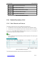
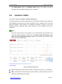
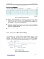
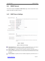
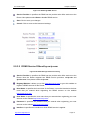
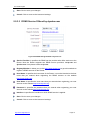
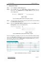
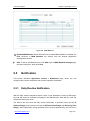
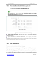
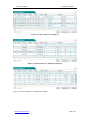
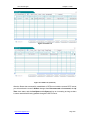
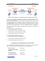
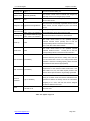
1
HiPER 518W Wireless Router Advanced Configuration Guide V1.3 UTT Technologies Co., Ltd. http://www.uttglobal.com Copyright Notice Copyright © 2000-2013. UTT Technologies Co., Ltd. All rights reserved. Information in this document, including URL and other Internet Web site references, is subject to change without further notice. Unless otherwise noted, the companies, organizations, people and events described in the examples of this document are fictitious, which have no relationship with any real company, organization, people and event. Complying with all applicable copyright laws is the responsibility of the user. No part of this document may be reproduced, stored in or introduced into a retrieval system, or transmitted in any form or by any means (electronic, mechanical, photocopying, recording, or otherwise), or used for any commercial and profit purposes, without the express prior written permission of UTT Technologies Co., Ltd. UTT Technologies Co., Ltd. has the patents, patent applications, trademarks, trademark applications, copyrights and other intellectual property rights that are mentioned in this document. You have no license to use these patents, trademarks, copyrights or other intellectual property rights, without the express prior written permission of UTT Technologies Co., Ltd. 艾泰® and UTT® are the registered trademarks of Technologies Co., Ltd. HiPER ® is the registered trademark of UTT Technologies Co., Ltd. Unless otherwise announced, the products, trademarks and patents of other companies, organizations or people mentioned herein are the properties of their respective owners. Product Number (PN): 0904-0101-001 Document Number (DN): PR-PMMU-1150.50-PPR-EN-1.0A UTT Technologies Table of Contents Table of Contents COPYRIGHT NOTICE..................................................................................................................... 2 TABLE OF CONTENTS ................................................................................................................... I ABOUT THIS MANUAL .................................................................................................................. 1 0.1 SCOPE ....................................................................................................................................... 1 0.2 WEB UI STYLE ......................................................................................................................... 1 0.3 DOCUMENTS CONVENTIONS ..................................................................................................... 2 0.3.1 Symbol Conventions ....................................................................................................... 2 0.3.2 Other Conventions ........................................................................................................... 2 0.3.3 Common Button Descriptions ......................................................................................... 2 0.3.4 Detailed Description of List ............................................................................................ 3 0.4 FACTORY DEFAULT SETTINGS ................................................................................................... 5 0.5 DOCUMENT ORGANIZATION ..................................................................................................... 5 0.6 CONTACT INFORMATION ........................................................................................................... 9 CHAPTER 1 PRODUCT OVERVIEW .................................................................................... 10 1.1 PRODUCT BRIEF...................................................................................................................... 10 1.2 KEY FEATURES ....................................................................................................................... 11 1.3 PHYSICAL SPECIFICATION ....................................................................................................... 12 1.4 DETAILED SPECIFICATIONS TABLE .......................................................................................... 12 CHAPTER 2 2.1 HARDWARE INSTALLATION .......................................................................... 14 PHYSICAL CHARACTERISTICS ................................................................................................. 14 2.1.1 Front Panel .................................................................................................................... 14 2.1.2 Rear Panel...................................................................................................................... 15 2.2 INSTALLATION PROCEDURE .................................................................................................... 16 CHAPTER 3 QUICK SETUP ................................................................................................... 19 3.1 CONFIGURING YOUR COMPUTER ............................................................................................ 19 3.2 LOGGING IN TO THE WIRELESS ROUTER ................................................................................. 21 3.3 SETUP WIZARD ....................................................................................................................... 23 3.3.1 Running the Setup Wizard ............................................................................................. 23 3.3.2 Setup Wizard - Internet Access Mode ........................................................................... 24 3.3.3 Setup Wizard - Internet Connection Settings ................................................................. 25 3.3.4 Setup Wizard - Wireless Settings................................................................................... 33 CHAPTER 4 START MENU .................................................................................................... 35 http://www.uttglobal.com Page I UTT Technologies Table of Contents 4.1 SETUP WIZARD ....................................................................................................................... 35 4.2 SYSTEM STATUS...................................................................................................................... 35 4.2.1 Wired Status .................................................................................................................. 35 4.2.2 Wireless Status .............................................................................................................. 36 4.3 INTERFACE TRAFFIC ............................................................................................................... 38 4.4 RESTART ................................................................................................................................. 40 CHAPTER 5 5.1 NETWORK ......................................................................................................... 41 WAN SETTINGS ...................................................................................................................... 41 5.1.1 Internet Connection List ................................................................................................ 41 5.1.2 Internet Connection Settings ......................................................................................... 45 5.2 LOAD BALANCING .................................................................................................................. 53 5.2.1 Introduction to Load Balancing and Failover ................................................................ 53 5.2.2 Load Balancing Global Settings .................................................................................... 55 5.2.3 Load Balancing List ...................................................................................................... 56 5.2.4 Connection Detection Settings ...................................................................................... 57 5.2.5 Identity Binding ............................................................................................................. 58 5.2.6 How to Configure Connection Detection Settings ........................................................ 59 5.3 LAN SETTINGS ....................................................................................................................... 60 5.4 DHCP SERVER........................................................................................................................ 62 5.4.1 DHCP Server Settings ................................................................................................... 62 5.4.2 Static DHCP .................................................................................................................. 64 5.4.3 DHCP Auto Binding ...................................................................................................... 66 5.4.4 DHCP Client List........................................................................................................... 67 5.4.5 Configuration Example for DHCP ................................................................................ 68 5.5 DDNS .................................................................................................................................... 71 5.5.1 Introduction to DDNS ................................................................................................... 71 5.5.2 Apply for a DDNS Account........................................................................................... 71 5.5.3 DDNS Settings .............................................................................................................. 72 5.5.4 DDNS Status ................................................................................................................. 75 5.5.5 DDNS Verification ........................................................................................................ 75 5.6 UPNP...................................................................................................................................... 76 5.6.1 Enable UPnP.................................................................................................................. 76 5.6.2 UPnP Port Forwarding List ........................................................................................... 76 5.7 NUMBER OF WAN ......................................................................................................................... 77 CHAPTER 6 6.1 WIRELESS ......................................................................................................... 78 BASIC WIRELESS SETTINGS .................................................................................................... 78 6.1.1 AP Mode ........................................................................................................................ 78 6.1.2 APClient Mode .............................................................................................................. 80 6.1.3 WDS .............................................................................................................................. 82 6.1.4 Configuration Example for WDS .................................................................................. 87 6.2 WIRELESS SECURITY SETTINGS .............................................................................................. 91 http://www.uttglobal.com Page II UTT Technologies Table of Contents 6.2.1 Disabling Wireless Security........................................................................................... 91 6.2.2 Wireless Security Settings – WEP ................................................................................. 91 6.2.3 Wireless Security Settings - WPA/WPA2 ...................................................................... 93 6.2.4 Wireless Security Settings - WPA-PSK/WPA2-PSK ..................................................... 94 6.3 WIRELESS MAC ADDRESS FILTERING .................................................................................... 96 6.3.1 MAC Address Filtering Global Settings ........................................................................ 96 6.3.2 MAC Address Filtering List .......................................................................................... 97 6.3.3 MAC Address Filtering Settings .................................................................................... 97 6.3.4 How to Configure MAC Address Filtering ................................................................... 98 6.3.5 Configuration Example for MAC Address Filtering ..................................................... 98 6.4 ADVANCED WIRELESS SETTINGS .......................................................................................... 100 6.5 WIRELESS CLIENT LIST ........................................................................................................ 102 CHAPTER 7 7.1 ADVANCED ..................................................................................................... 103 NAT AND DMZ .................................................................................................................... 103 7.1.1 Introduction to NAT Features ...................................................................................... 103 7.1.2 Port Forwarding ........................................................................................................... 105 7.1.3 NAT Rule ..................................................................................................................... 109 7.1.4 DMZ ............................................................................................................................ 115 7.2 STATIC ROUTE ...................................................................................................................... 116 7.2.1 Introduction to Static Route ......................................................................................... 116 7.2.2 Static Route List .......................................................................................................... 116 7.2.3 Static Route Settings.................................................................................................... 117 7.2.4 How to Add Static Routes ........................................................................................... 118 7.3 POLICY ROUTING .................................................................................................................. 119 7.3.1 Policy Routing Settings ............................................................................................... 120 7.3.2 Enable Policy Routing ................................................................................................. 122 7.3.3 Policy Routing List ...................................................................................................... 122 7.4 ANTI-NETSNIPER.................................................................................................................. 123 7.5 PLUG AND PLAY .................................................................................................................... 123 7.5.1 Introduction to Plug and Play ...................................................................................... 123 7.5.2 Enable Plug and Play ................................................................................................... 124 7.6 SYSLOG ................................................................................................................................ 125 7.7 SNMP .................................................................................................................................. 125 CHAPTER 8 8.1 USER MANAGEMENT ................................................................................... 127 USER STATUS ........................................................................................................................ 127 8.1.1 User Application Analysis Pie Charts .......................................................................... 127 8.1.2 User Status List ........................................................................................................... 128 8.2 IP/MAC BINDING ................................................................................................................. 129 8.2.1 Introduction to IP/MAC Binding ................................................................................. 130 8.2.2 IP/MAC Binding Global Settings ................................................................................ 131 8.2.3 IP/MAC Binding List .................................................................................................. 132 http://www.uttglobal.com Page III UTT Technologies Table of Contents 8.2.4 IP/MAC Binding Settings ............................................................................................ 133 8.2.5 How to Add IP/MAC Bindings ................................................................................... 134 8.2.6 Internet Whitelist and Blacklist ................................................................................... 135 8.3 PPPOE SERVER ..................................................................................................................... 137 8.3.1 PPPoE Overview ......................................................................................................... 138 8.3.2 PPPoE Server Global Settings ..................................................................................... 140 8.3.3 PPPoE Account List .................................................................................................... 141 8.3.4 PPPoE Account Settings .............................................................................................. 142 8.3.5 PPPoE User Status ....................................................................................................... 144 8.3.6 Export PPPoE Accounts .............................................................................................. 145 8.3.7 Import PPPoE Accounts .............................................................................................. 145 8.4 WEB AUTHENTICATION ........................................................................................................ 146 8.4.1 Enable Web Authentication ......................................................................................... 146 8.4.2 Web Authentication User Account Settings ................................................................. 147 8.4.3 Web Authentication User Account List ....................................................................... 148 8.4.4 How to Use Web Authentication ................................................................................. 149 8.5 USER GROUP ........................................................................................................................ 151 8.5.1 Introduction to User Group ......................................................................................... 151 8.5.2 User Group Settings .................................................................................................... 152 8.5.3 User Group List ........................................................................................................... 153 8.5.4 How to Add the User Groups ...................................................................................... 154 8.5.5 How to Edit an User Group ......................................................................................... 154 CHAPTER 9 APPLICATION CONTROL ............................................................................. 156 9.1 SCHEDULE ............................................................................................................................ 156 9.2 APPLICATION CONTROL ....................................................................................................... 157 9.2.1 Internet Application Management List ........................................................................ 158 9.2.2 Internet Application Management Settings ................................................................. 158 9.2.3 Internet Application Management Configuration Example ......................................... 160 9.3 QQ WHITELIST ..................................................................................................................... 163 9.4 MSN WHITELIST .................................................................................................................. 164 9.5 NOTIFICATION....................................................................................................................... 165 9.5.1 Daily Routine Notification .......................................................................................... 165 9.5.2 Account Expiration Notification ................................................................................. 167 9.6 APPLICATION AUDIT ............................................................................................................. 168 9.6.1 View Audit Log ........................................................................................................... 168 9.6.2 Log Management ......................................................................................................... 169 9.7 POLICY DATABASE ................................................................................................................ 170 CHAPTER 10 10.1 QOS .................................................................................................................. 171 FIXED RATE LIMITING .......................................................................................................... 171 10.1.1 Fixed Rate Limiting Rule List ..................................................................................... 171 10.1.2 Fixed Rate Limiting Rule Settings .............................................................................. 172 http://www.uttglobal.com Page IV UTT Technologies Table of Contents 10.2 FLEXIBLE BANDWIDTH MANAGEMENT ................................................................................ 173 10.3 P2P RATE LIMIT.................................................................................................................... 173 10.4 SESSION LIMITING ................................................................................................................ 175 CHAPTER 11 11.1 FIREWALL ....................................................................................................... 177 ATTACK PREVENTION ........................................................................................................... 177 11.1.1 Internal Attack Prevention ........................................................................................... 177 11.1.2 External Attack Prevention .......................................................................................... 180 11.2 ACCESS CONTROL ................................................................................................................ 181 11.2.1 Introduction to Access Control .................................................................................... 181 11.2.2 Access Rule List .......................................................................................................... 183 11.2.3 Access Rule Settings ................................................................................................... 184 11.2.4 Configuration Examples for Access Rule .................................................................... 189 11.3 DOMAIN FILTERING .............................................................................................................. 195 11.3.1 Domain Filtering Global Settings ................................................................................ 195 11.3.2 Domain Filtering Settings ............................................................................................ 195 11.4 10.4 MAC ADDRESS FILTERING ........................................................................................... 196 11.4.1 MAC Address Filtering List ........................................................................................ 197 11.4.2 MAC Address Filtering Setting ................................................................................... 197 CHAPTER 12 12.1 VPN ................................................................................................................... 199 PPTP VPN............................................................................................................................ 199 12.1.1 Introduction to PPTP Implementation ......................................................................... 199 12.1.2 PPTP Client Settings ................................................................................................... 204 12.1.3 PPTP Server Settings ................................................................................................... 205 12.1.4 Notes on Configuring PPTP Client and Server............................................................ 208 12.1.5 PPTP List ..................................................................................................................... 208 12.1.6 How to Add, View, Edit and Delete PPTP Clients or Server Entries ........................... 210 12.1.7 Configuration Example for PPTP ................................................................................ 211 12.2 IPSEC VPN........................................................................................................................... 212 12.2.1 Introduction to IPSec Implementation ......................................................................... 212 12.2.2 IPSec Settings–AutoKey (IKE) ................................................................................... 228 12.2.3 IPSec List .................................................................................................................... 238 12.2.4 How to Add, View, Edit and Delete IPSec Entries ...................................................... 239 12.2.5 Configuration Examples for IPSec – AutoKey (IKE) ................................................. 240 CHAPTER 13 13.1 SYSTEM ........................................................................................................... 248 ADMINISTRATOR ................................................................................................................... 248 13.1.1 Administrator List ....................................................................................................... 248 13.1.2 Administrator Settings ................................................................................................. 249 13.2 SYSTEM TIME ....................................................................................................................... 250 13.3 CONFIGURATION ................................................................................................................... 252 13.3.1 Backup Configuration ................................................................................................. 252 13.3.2 Restore Configuration ................................................................................................. 252 http://www.uttglobal.com Page V UTT Technologies 13.3.3 Table of Contents Reset to Factory Defaults ............................................................................................ 253 13.4 FIRMWARE UPGRADE............................................................................................................ 254 13.5 REMOTE MANAGEMENT ....................................................................................................... 255 13.6 SCHEDULED TASK................................................................................................................. 256 13.6.1 Scheduled Task Settings .............................................................................................. 257 13.6.2 Scheduled Task List ..................................................................................................... 257 CHAPTER 14 STATUS ............................................................................................................ 259 14.1 INTERFACE STATUS ............................................................................................................... 259 14.2 SYSTEM INFORMATION ......................................................................................................... 259 14.3 SYSTEM LOG ........................................................................................................................ 260 14.3.1 Log Management Settings ........................................................................................... 261 14.3.2 System Log Information .............................................................................................. 261 CHAPTER 15 SUPPORT ........................................................................................................ 264 APPENDIX A HOW TO CONFIGURE YOUR PC ..................................................................... 265 APPENDIX B FAQ ...................................................................................................................... 269 1. HOW TO CONNECT THE WIRELESS ROUTER TO THE INTERNET USING PPPOE? ...................... 269 2. HOW TO CONNECT THE WIRELESS ROUTER TO THE INTERNET USING STATIC IP? .................. 270 3. HOW TO CONNECT THE WIRELESS ROUTER TO THE INTERNET USING DHCP? ...................... 270 4. HOW TO CONNECT A WINDOWS XP PC TO THE DEVICE WIRELESSLY? .................................. 272 5. HOW TO CONNECT A WINDOWS 7 PC TO THE DEVICE WIRELESSLY? ..................................... 273 6. HOW TO RESET THE WIRELESS ROUTER TO FACTORY DEFAULT SETTINGS? ................................ 274 APPENDIX C COMMON IP PROTOCOLS ............................................................................... 275 APPENDIX D COMMON SERVICE PORTS ............................................................................. 276 APPENDIX E FIGURE INDEX.................................................................................................... 281 APPENDIX F TABLE INDEX ...................................................................................................... 287 http://www.uttglobal.com Page VI UTT Technologies About This Manual About This Manual 0.1 Scope This guide mainly describes how to install and configure the HiPER 518W Wireless Router offered by UTT Technologies Co., Ltd. For more information, please visit our website at www.uttglobal.com. 0.2 Web UI Style The Web UI style complies with the browser standard, which is as follows: Radio Button: It allows you to choose only one of a predefined set of options. Check Box: It allows you to choose one or more options. Button: It allows you to click to perform an action. Text Box: It allows you to enter text information. List Box: It allows you to select one or more items from a list contained within a static, multiple line text box. Drop-down List: It allows you to choose one item from a list. When a drop-down list is inactive, it displays a single item. When activated, it drops down a list of items, from which you may select one. http://www.uttglobal.com Page 1 UTT Technologies About This Manual 0.3 Documents Conventions 0.3.1 Symbol Conventions : It represents a configuration parameter. Parameters may be optional or required. Required parameters are indicated by a red asterisk (*). : It represents a button. : It represents one or more notes. 0.3.2 Other Conventions 0.3.2.1 Convention for a Page Path First Level Menu Item > Second Level Menu Item (bold font) means the menu path to open a page. For example, Wireless > MAC Filtering means that in the Web UI, click the first level menu item Wireless firstly, and then click the second level menu item MAC Filtering to open the corresponding page. 0.3.2.2 Convention for Clicking a Button Click the XXX button (XXX is the name of the button, bold font) means performing the corresponding operation. E.g., click the Delete button means performing the delete operation, the Delete button is shown as 0.3.3 . Common Button Descriptions The following table describes the commonly-used buttons in the Web UI. Button Description Click to save your changes. http://www.uttglobal.com Page 2 UTT Technologies About This Manual Click to revert to the last saved settings. Click to delete the selected entry(s). Click to display the latest information on the page. Click to clear all the statistics on the page. Click to go back to the previous page. Table 0-1 Common Button Descriptions 0.3.4 Detailed Description of List 0.3.4.1 Basic Elements and Features The Web UI contains two kinds of lists: editable list and read-only list. ● An editable list is used to add, display, modify and delete the configuration entries. ● A read-only list is used to display the system status information which is not editable. Let’s take the editable MAC Address Filtering List (see Figure 0-1) as an example to explain the basic elements and features of the list. Note Only the editable lists support Add, Modify, and Delete operations. The read-only lists don’t support them. Figure 0-1 MAC Address Filtering List The following table describes the basic elements and features of the list. http://www.uttglobal.com Page 3 UTT Technologies About This Manual Element Description Current page number/ total pages, the example means that the current page is the first page, and total one page. Click to jump to the first page. Click to jump to the previous page. Click to jump to the next page. Click to jump to the last page. Enter page number in text field, then click Go to or press <Enter> key to jump to that page. Enter the text string you want to search for in this text box, then press <Enter> key to display all the matched entries. In addition, you can do the search within the displayed results. If you want to display all the entries, you only need clear the text box and then press <Enter> key. Note that the matching rule is substring matching, that is, it will search for and display those entries that contain the specified text string. Configured number / maximum number, the example means that there are 2 configured MAC address filtering entries, and the maximum number of MAC address filtering allowed is 50. Click to go to the setup page to modify the corresponding entry. Click to delete the corresponding entry. Click (add the check mark) to select all the entries in the current page. Click again (remove the check mark) to unselect all the entries in the current page. Click to go to the setup page to add a new entry to the list. Click to delete all the entries in the list. To delete one or more entries, select the leftmost check boxes of them, and then click the Delete button. Table 0-2 Basic Elements and Features of the List http://www.uttglobal.com Page 4 UTT Technologies About This Manual 0.3.4.2 Sorting Function All the lists in the Web UI support sorting function. The operation is as follows: You can click any column header to sort the entries in a list by that column. Click once to sort the entries in descending order, click again to sort them in ascending order. Click a third time to sort them in descending order, and so forth. After sorted, the list will be displayed from the first page. 0.4 Factory Default Settings The following table lists the default values of several important parameters. Parameter Default Value Description Administrator User Name admin You can use the administrator account to login to the Wireless Router’s Web UI. Administrator Password admin Note: Both the User Name and Password are case sensitive. LAN IP Address 192.168.1.1 They are the IP address and subnet mask of the Wireless Router’s LAN interface. You can LAN Subnet Mask 255.255.255.0 use this IP address to access and manage the Wireless Router. To connect to the Wireless Router, wireless clients must use the same SSID as the SSID UTT-HIPER_XXXXXX Wireless Router. Therein, “XXXXXX” is the Wireless Router’s serial number in hexadecimal format. Table 0-3 Factory Default Settings 0.5 Document Organization This guide mainly describes the settings and applications of the HiPER 518W Wireless Router, which include product overview, hardware installation, quick setup, start menu, network, wireless, advanced, user management, firewall, VPN, System, status and support. http://www.uttglobal.com Page 5 UTT Technologies About This Manual Chapter 1 Product Overview This chapter describes functions and features of the Wireless Router. Chapter 2 Hardware Installation This chapter describes how to install the Wireless Router. Chapter 3 Quick Setup This chapter describes the following contents: How to install and configure TCP/IP properties on your PC. How to login to the Wireless Router; and introduction to the WEB UI layout. How to use the Setup Wizard to quickly configure the basic parameters for the Wireless Router to operate properly. Chapter 4 Start Menu This chapter describes how to quickly go to the following pages to configure the related features via the Start menu items: Setup Wizard: How to configure the basic parameters for the Wireless Router to operate properly. System Status: How to view wired and wireless status of the Wireless Router. Interface Traffic: How to view the real-time traffic chart for each interface, and the ingress and egress traffic statistics for each interface. Restart: How to restart the Wireless Router. Chapter 5 Network This chapter describes how to configure the basic network parameters of the Wireless Router, including: WAN: How to configure Internet connections and view their configuration and status. Load Balancing: How to configure the load balancing feature which includes detection and weight settings, global settings; and how to view the load balancing list. LAN Settings: How to configure the parameters of the LAN interface, such as IP address, subnet mask, MAC address, and so on. DHCP Server: How to configure DHCP server, DNS proxy, static DHCP; how to view the static DHCP list and DHCP client list. DDNS: How to apply for DDNS account and configure DDNS service, and view DDNS status. UPnP: How to enable or disable UPnP, and view the UPnP port forwarding list. Chapter 6 Wireless http://www.uttglobal.com Page 6 UTT Technologies About This Manual This chapter describes how to configure the wireless features of the Wireless Router, including: Basic Wireless Settings: How to configure basic wireless settings. Wireless Security Settings: How to configure wireless security settings. Wireless MAC Address Filtering: How to filter the wireless clients based on their MAC addresses. Advanced Wireless Settings: How to configure advanced wireless settings. Wireless Client List: How to view the status of the wireless clients, and easily configure MAC address filtering entries via the list. Chapter 7 Advanced This chapter describes how to configure the advanced features of the Router, including: NAT and DMZ: How to configure and view NAT rules, port forwarding entries and DMZ host. Static Route: How to configure and view the static routes. Policy Routing: How to configure and view the policy routings. Anti-NetSniper: How to enable Anti-Netsniper. Plug and Play: How to enable Plug and play Syslog: How to configure syslog. SNMP: How to configure SNMP. Chapter 8 User Management This chapter describes how to control the LAN users, including: User Status: How to view user status. IP/MAC Binding: How to configure IP/MAC bindings to prevent IP address spoofing. How to configure an Internet whitelist or blacklist for the LAN users. PPPoE Server: How to configure PPPoE server global settings and PPPoE account settings, and view PPPoE user status. Web Authentication: How to configure web authentication global settings and web authentication account settings. User Group: How to configure and view user group. Chapter 9 Applications Control This chapter describes how to control and manage the Applications of the LAN users based on schedule, including: Schedule: How to configure and view schedule. Applications Control: How to configure and view application control. http://www.uttglobal.com Page 7 UTT Technologies QQ Whitelist: How to configure and view QQ whitelist. MSN Whitelist: How to configure and view MSN whitelist. Notification: How to configure notification. Application Audit: How to view application audic. Policy Database: How to configure policy database. About This Manual Chapter 10 QoS Fixed Rate Limiting: How to configure fixed rate limiting. Flexible Bandwidth: How to configure flexible bandwidth. P2P Rate Limit: How to configure P2P rate limiting. Session Limiting: How to configure session limiting. Chapter 11 Firewall This chapter describes how to configure firewall features, including: Attack Prevention: How to configure attack prevention features. Access Control: How to configure access control rules to assign Internet access privileges to the LAN users based on schedule, and to prevent external attacks. Domain Filtering: How to configure domain filtering feature to block access to the specified websites. MAC Address Filtering: How to configure MAC address filtering to block or allow specified hosts. Chapter 12 VPN This chapter describes the PPTP and IPsec implementation, and how to configure the Router as a server/client. Chapter 13 System This chapter describes how to perform maintenance activities on the Router, including: Administrator: How to add, view, modify and delete the administrator accounts. Time: How to set the system date and time manually or automatically. Configuration: How to backup and restore the system configuration, and reset the Router to factory default settings. Firmware upgrade: How to backup, download and upgrade firmware. Remote Management: How to enable HTTP remote management feature to remotely configure and manage the Router via Internet. Scheduled Task: How to create and view the scheduled tasks. Now the Router only http://www.uttglobal.com Page 8 UTT Technologies About This Manual supports one scheduled task: Restart. Chapter 14 Status This chapter describes how to view the system status information and statistics, including: Interface Status: It displays traffic statistics of the Router. System Information: It displays the current system time, system up time, system resources usage information, SN, firmware version, and system log messages. System Log: How to configure and view system log. Chapter 15 Support This chapter describes how to link to the UTTCare, Forum, Knowledge and Reservation page of the UTT website, which can help you quickly learn the UTT Technologies service system and enjoy the most intimate and professional services. Appendix This guide provides six appendixes, including: Appendix A How to Configure Your PC: How to configure TCP/IP settings on a Windows XP-based computer. Appendix B FAQ: Frequent questions and answers. Appendix C Common IP Protocols: Provides the list of common IP protocols and their protocol numbers. Appendix D Common Service Ports: Provides the list of common services and their port numbers. Appendix E Figure Index: Provides a figure index directory. Appendix F Table Index: Provides a table index directory. 0.6 Contact Information If you have any questions regarding the operation or installation of the HiPER 518W Wireless Router, please contact us in any of the following ways. Technical Support Phone: +1(626)722-5032 E-mail: [email protected] http://www.uttglobal.com Page 9 UTT Technologies Chapter 1 Product Overview Chapter 1 Product Overview Thanks for choosing the HiPER 518W Wireless Router from UTT Technologies Co., Ltd. This chapter describes the functions and features of the HiPER 518W Wireless Router in brief. 1.1 Product Brief The HiPER 518W Wireless Router is designed for small-sized businesses and branch offices, integrating wired networks with 3G and 802.11 wireless networks. In addition, it adheres to the characteristics of UTT Technologies products: open, easy-to-use, safe, smooth, and so on. The HiPER 518W has three models: HiPER 518W Plus, HiPER 518W VPN, HiPER 518W Lite. This manual is base on HiPER 518W Plus. The HiPER 518W is based on IEEE 802.11n standard and is compatible with IEEE 802.11b and IEEE 802.11g standards. It provides maximum wireless transfer rate up to 300Mbps, wide wireless coverage, and stable wireless data transmission. The HiPER 518W supports multiple security modes which include WEP, WPA-Enterprise, WPA2-Enterprise, WPA-PSK and WPA2-PSK. What’s more, it provides simple and efficient wireless MAC address filtering to improve the security of your wireless network. The HiPER 518W supports DHCP server, NAT, static route, DDNS, IP/MAC binding, PPPoE server and other advanced features. Furthermore, it provides feature-rich user management, which can help you control and manage the Internet behaviors of the LAN users based on schedule and address group, including QQ, MSN and P2P applications (e.g., Bit Comet, Bit Spirit, and Thunder Search) control, the maximum upload and download rate limiting. The HiPER 518W supports flexible firewall features like access control and domain filtering to effectively prevent network attacks, and provide security for the LAN users. The HiPER 518W provides a concise, intuitive, and feature-rich Web User Interface. The Setup Wizard can help you quickly configure the basic parameters for the Wireless Router to operate properly. The status information (System Status, Wireless Client List, Traffic Statistics, etc.) can help you identify and diagnose the source of current system problems, or predict potential system problems. In addition, the Support page provides links to the UTT website to help you quickly learn the UTT Technologies service system and enjoy the most intimate and professional services. http://www.uttglobal.com Page 10 UTT Technologies 1.2 Chapter 1 Product Overview Key Features Supports multiple Internet connection types: 3G, PPPoE, Static IP, DHCP and Wi-Fi AP Provides two wired WAN interfaces (WAN1 and WAN2), two wireless WAN interfaces (3G and APClient), and three 10M/100M LAN ports Supports multiple Internet connections that provide intelligent load balancing and automatic failover Supports 6kV lightning protection Conforms to IEEE 802.11n (802.11g and 802.11b Compatible). Provides maximum wireless transfer rate up to 300Mbps Supports multiple wireless security modes which include WEP, WPA-Enterprise, WPA2-Enterprise, WPA-PSK and WPA2-PSK Supports hidden SSID Supports VPN pass-through (IPSec, PPTP) Supports PPTP VPN and IPSec VPN Supports QoS Supports WMM (Wi-Fi Multimedia) Supports wireless MAC address filtering feature, whitelist, blacklist, one-click filtering of MAC addresses Supports DHCP server Supports DNS proxy Supports DDNS (Dynamic Domain Name System) Supports IP/MAC binding Supports feature-rich PPPoE server Supports upload and download rate limiting for the LAN users Supports Internet behavior management for the LAN users, such as block or allow QQ, MSN and P2P applications (e.g., Bit Comet, Bit Spirit, and Thunder Search) Supports flexible and strong firewall features Supports IP packet filtering based on IP address, protocol and TCP/UDP port Supports URL and keyword filtering Supports DNS request filtering Supports HTTP remote management Provides the Web User Interface (Web UI) for ease of use Supports firmware upgrade via the Web UI http://www.uttglobal.com Page 11 UTT Technologies Chapter 1 Product Overview Supports configuration backup and restore Provides wireless client list and system status 1.3 Physical Specification ● Conforms to IEEE 802.11n, IEEE 802.11b and IEEE 802.11g standards ● Conforms to IEEE 802.3 Ethernet and IEEE 802.3u Fast Ethernet standards ● Supports TCP/IP, PPPoE, DHCP, ICMP, NAT, Static Route, etc. ● Each physical port supports auto-negotiation for the port speed and duplex mode ● Each physical port supports auto MDI/MDI-X ● Provides system and port LEDs ● Operating Environment: Temperature: 32°to 104°F (0°to 40°C) Relative Humidity: 10% to 90%, Non-condensing Height: 0m to 4000m 1.4 Detailed Specifications Table The HiPER 518W has three models: HiPER 518W Plus, HiPER 518W VPN, HiPER 518W Lite. The features and specifications of each model are different. The following table lists detailed specifications for each model. Model Name HiPER 518W-Plus HiPER 518W-VPN HiPER 518W-Lite WAN 1 to 4(2) 1 to 4(2) 1 to 4(2) LAN 4 to 1(3) 4 to 1(3) 4 to 1(3) USB 1 1 1 Dimension 182mm×129mm×27 mm 182mm×129mm×2 7mm 182mm×129mm×27 mm Input Voltage DC:12V 1A DC:12V 1A DC:12V 1A Power Consumption Max 6W Max 6W Max 6W Forwarding Capability 30K PPS 30K PPS 30K PPS Max Concurrent Clients 30 30 30 TX by Rv 2×2 2×2 2×2 http://www.uttglobal.com Page 12 UTT Technologies Chapter 1 Product Overview 2.4GHz Y Y Y 5GHz -- -- -- PPTP VPN 5/5 5/5 5/5 IPSecVPN 5/5 5/5 -- Load Balance Y Y Y NAT Y Y Y DDNS(No-IP; Dyndns) Y Y Y Block/ Y Y Y Web Authenticatoin/Billin g Y Y Y PPPoE Server/Billing Y Y Y DHCP Server Y Y Y Wireless Standard IEEE 802.11 b/g/n IEEE 802.11 b/g/n IEEE 802.11 b/g/n Wireless Security WEP/WPA-PSK/TKI P/ WPA2-PSK/AES WEP/WPA-PSK/T KIP/ WPA2-PSK/AES WEP/WPA-PSK/TKI P/ WPA2-PSK/AES Througput Radio 300Mbps 300Mbps 300Mbps 3G USB Modem E1750,E261,E169,Z TE-MF637U -- E1750,E261,E169,Z TE-MF637U 3G Standard WCDMA, CDMA -2000, TD-SCDMA WCDMA, CDMA 2000, TD-SCDMA Antennas Gain 2, 7 dBi 2, 7 dBi 2, 7 dBi SNMP V1/V2 V1/V2 V1/V2 Web UI/CLI Y Y Y Domain Notification per Table 1-1 http://www.uttglobal.com Page 13 UTT Technologies Chapter 2 Hardware Installation Chapter 2 Hardware Installation 2.1 Physical Characteristics 2.1.1 Front Panel As shown in Figure 2-1, the LEDs are located on the front panel of the Wireless Router. The LEDs indicate the status of the system and each port. Table 2-1 describes these LEDs. Figure 2-1 Front Panel of the Wireless Router LED Full Name State Description The Wireless Router is powered on. On PWR Power LED Off Blinking SYS USB WLAN System LED 3G USB Modem Status LED The Wireless Router is powered off. The system is operating properly. On The system is not operating properly. Off The system is not operating properly. On A 3G USB modem is connected to the USB port. Off No 3G USB modem is connected. On The wireless function is enabled. Wireless LAN Status LED http://www.uttglobal.com Blinking The Wireless Router is sending or receiving data over the wireless network. Page 14 UTT Technologies Chapter 2 Hardware Installation WAN1/ WAN1/WAN2 WAN2 Port Status LED 1, 2, 3 LAN Port Status LED Off The wireless function is disabled. On A valid link is established on the corresponding port. Blinking The corresponding port is sending or receiving data. Off No link is established on the corresponding port. On A valid link is established on the corresponding port. Blinking The corresponding port is sending or receiving data. Off No link is established on the corresponding port. Note: The Wireless Router doesn’t support WPS feature at present. Table 2-1 Description of LEDs on the Front Panel 2.1.2 Rear Panel As shown in Figure 2-2, the rear panel of the Wireless Router contains a POWER connector, a RESET button, a USB port, two wired WAN ports (WAN1 and WAN2), three LAN ports, a WPS button, and two Antenna ports. Note that the Wireless Router doesn’t support WPS feature at present. Figure 2-2 Back Panel of the Wireless Router 1. RESET Button If you forget the administrator password, you need to use the RESET button to reset the Wireless Router to factory default settings. The operation is as follows: While the Wireless Router is powered on, use a pin or paper clip to press and hold the RESET button for more than 5 seconds, and then release the button. After that, the Wireless Router will http://www.uttglobal.com Page 15 UTT Technologies Chapter 2 Hardware Installation restart with factory default settings. Note This operation will clear all the custom settings on the Wireless Router. If you remember the administrator account, it is strongly recommended that you go to Administration > Configuration page to backup the current configuration firstly, and then reset the Wireless Router to factory default settings. 2. Ports The Wireless Router provides three LAN ports, two WAN ports, and a USB port. Table 2-2 describes these ports. Port Description LAN (1, 2, 3) WAN1/WAN2 They are used to connect the wired computers, hubs, switches, and other Ethernet network devices on the LAN to the Wireless Router. They are used to connect the Wireless Router to the Internet. The Wireless Router provides a USB port for connecting a 3G USB Modem, which USB is used to connect the Wireless Router to the Internet. Table 2-2 Description of Ports on the Rear Panel 3. Components Component Number Description Antenna 2 They are used to receive and transmit wireless signals. Power 1 It is used to connect the power adapter. Table 2-3 Description of Components on the Rear Panel 2.2 Installation Procedure 1. Selecting a Proper Location Please make sure that the Wireless Router is powered off before installing it. Then you need to select a proper location to install the Wireless Router. In most cases, you can install it on a level surface such as a desktop or shelf. http://www.uttglobal.com Page 16 UTT Technologies Chapter 2 Hardware Installation Note Please ensure that the desktop or shelf is stable and the power outlet is grounded properly, and do not place heavy objects on the Wireless Router. 2. Attach the Antennas When shipped, the two antennas are not connected to the Wireless Router. To attach the antennas to the Wireless Router, follow these steps: 1) Remove one antenna from the box. 2) Locate one antenna port (threaded knob) on the back panel of the Wireless Router, see Figure 2-2. 3) Screw the antenna in a clockwise direction to the threaded knob until firmly seated. Don’t over-tighten. 4) Repeat the above steps to attach the other antenna. Note Please make sure that you have attached the two antennas to the Wireless Router properly. The antennas will greatly enhance wireless communication capacity of the Wireless Router. 3. Connecting the Wireless Router to the LAN Connect a standard network cable from a PC or switch to a LAN port of the Wireless Router, or connect a PC to the Wireless Router wirelessly. The Wireless Router will automatically adapt to any network device operating at 10Mbps or 100Mbps. 4. Connecting the Wireless Router to the Internet Connect the network cable provided by the manufacturer from the DSL, cable or fiber optic modem to a WAN port of the Wireless Router, or insert your 3G USB modem to the USB port of the Wireless Router. 5. Powering On the Wireless Router Connect the supplied power cord to the power connector on the rear panel of the Wireless Router, and then plug the other end of the power cord to a grounded power outlet. The Wireless Router will start automatically. Note http://www.uttglobal.com Page 17 UTT Technologies Chapter 2 Hardware Installation To prevent the Wireless Router from working abnormally or being damaged, please make sure that the power supply and connectivity are normal, and the power outlet is grounded properly before powering on the Wireless Router. 6. Checking the LEDs Verify that the Wireless Router starts up properly and the network connections are operational by checking the LED states, as described in Table 2-1. http://www.uttglobal.com Page 18 UTT Technologies Chapter 3 Quick Setup Chapter 3 Quick Setup This chapter describes how to properly configure TCP/IP settings on your computer, how to login to the Wireless Router, and how to configure the basic parameters to quickly connect the Wireless Router to the Internet via the Start > Setup Wizard. In addition, it also briefly describes the layout and style of the Wireless Router’s Web UI. 3.1 Configuring Your Computer Before configuring the Wireless Router via the Web UI, you should properly configure TCP/IP settings on the computer that you use to administer the Wireless Router. To do this, follow these steps: Step 1 Connect the computer to a LAN port of the Wireless Router. Step 2 Install TCP/IP protocol on your computer. If it has been installed, please ignore it. Step 3 Configure TCP/IP settings on your computer: set the computer’s IP address to an IP address in the range of 192.168.1.2 through 192.168.1.254, set its subnet mask to 255.255.255.0, set its default gateway to 192.168.16.1 (the Wireless Router’s default LAN IP address is 192.168.1.1 with a subnet mask of 255.255.255.0), and set its DNS server to an available IP address provided by your ISP. Step 4 To verify the network connection between your computer and the Wireless Router, you can use the ping command at the command prompt on the computer: Ping 192.168.1.1 If the displayed page is similar to the screenshot below, the connection between your computer and the Wireless Router has been established. http://www.uttglobal.com Page 19 UTT Technologies Chapter 3 Quick Setup If the displayed page is similar to the screenshot below, the connection between your computer and the Wireless Router hasn't been established yet. If the connection hasn't been established, please take the following steps to resolve the problem: 1. Is the physical link between your computer and the Wireless Router connected properly? Verify that the LED corresponding to the Wireless Router’s LAN port and the LED on your computer’s adapter are lit. 2. Is the TCP/IP configuration for your PC correct? Verify that your computer is on the same subnet as the Wireless Router’s LAN interface. For example, if the Wireless Router’s LAN IP address is 192.168.1.1/24 (default value), your computer’s IP address must be an IP address in the range of 192.168.1.2 through 192.168.1.254, which is not being used by another network device; and its default gateway must be 192.168.1.1. http://www.uttglobal.com Page 20 UTT Technologies 3.2 Chapter 3 Quick Setup Logging in to the Wireless Router This section describes how to login to the Wireless Router. No matter what operating system is installed on your computer, such as, MS Windows, Macintosh, UNIX, or Linux, and so on, you can login to and configure the Wireless Router through the Web browser (for example, Internet Explorer). To login to the Wireless Router, do the following: Open a Web browser, enter the Wireless Router’s LAN interface IP address (the default is 192.168.1.1) in the address bar, and then press <Enter> key, see Figure 3-1. Figure 3-1 Entering IP address in the Address Bar A login screen prompts you for your user name and password, see Figure 3-2. When you first login to the Wireless Router, please use the default administrator account: Enter admin in both the User name and Password boxes (the default user name and password both are admin), lastly click OK. Figure 3-2 Login Screen If your user name and password are correct, it will display the homepage, see Figure 3-3. http://www.uttglobal.com Page 21 UTT Technologies Chapter 3 Quick Setup Top Pane Side Pane Main Pane Bottom Pane Figure 3-3 Homepage Each page of the Wireless Router’s Web UI consists of four panes: 1. Top Pane: It displays UTT logo, model and version, and three shortcut icons. 1) UTT Logo: Click to link to the homepage of the UTT website. 2) Model and Version: The product model and firmware version of the Wireless Router. 3) Short Icons: They are used for fast link to the corresponding pages on the website of UTT Technologies Co., Ltd. ● Product: Click to link to the products page of the UTT website to find more products. ● Forum: Click to link to the forum homepage of the UTT website to participate in product discussions. ● Feedback: Click to link to send us your feedback by E-mail. 2. Main Pane: It is the location where you can configure each feature of the Wireless Router, view configuration, status and statistics. 3. Side Pane: It displays the two-level main menu bar (i.e., navigation bar). The first level menu is always visible. The second level menu is hidden by default. You can click a first level menu item to reveal its submenu items, click again to hide them. 4. Bottom Pane: It displays copyright information. If this is the first time that you login to the Wireless Router, the first page of the Setup Wizard appears. In the next section we will describe how to use the Setup Wizard to configure the basic parameters for the Wireless Router to operate properly. http://www.uttglobal.com Page 22 UTT Technologies 3.3 Chapter 3 Quick Setup Setup Wizard This section describes the Start > Setup Wizard page. 3.3.1 Running the Setup Wizard As mentioned earlier, the first page of the Setup Wizard appears immediately after your first login, see the following figure. Figure 3-4 Running the Setup Wizard Do Not Automatically Launch the Wizard Again: If you select this check box, the system don’t automatically launch the Setup Wizard the next time you login to the Wireless Router, instead directly open the Welcome page shown in Figure 3-5. Else, the system will still launch the Setup Wizard automatically. Exit Wizard: Click to exit the Setup Wizard and go to the Welcome page (see Figure 3-5). The changes made in the Setup Wizard will be discarded. Next: Click to go to the next page of the Setup Wizard, that is, the Setup Wizard Internet Access Mode page shown in Figure 3-6. http://www.uttglobal.com Page 23 UTT Technologies Chapter 3 Quick Setup Figure 3-5 Welcome Page 3.3.2 Setup Wizard - Internet Access Mode In this page, you can choose one or more Internet connections that you want to configure via the Setup Wizard, see Figure 3-6. Figure 3-6 Setup Wizard - Internet Access Mode WAN1: If you want to configure a wired Internet connection on the WAN1 interface via the Setup Wizard, select this check box. WAN2: If you want to configure a wired Internet connection on the WAN2 interface http://www.uttglobal.com Page 24 UTT Technologies Chapter 3 Quick Setup via the Setup Wizard, select this check box. 3G Client: If you want to configure a 3G Internet connection via the Setup Wizard, select this check box. Here the Wireless Router acts as a 3G client. AP Client: If you want to configure a wireless Internet connection via the Setup Wizard, select this check box. Here the Wireless Router acts as an AP client. Back: Click to go back to the previous page of the Setup Wizard. Cancel: Click to revert to the last saved settings. Exit Wizard: Click to exit the Setup Wizard and go to the Welcome page (see Figure 3-5). The changes made in the Setup Wizard will be discarded. Next: Click to go to the next page of the Setup Wizard. 3.3.3 Setup Wizard - Internet Connection Settings In the Setup Wizard, you can configure each Internet connection respectively. For each Internet access mode, the Internet connection settings are different. 3.3.3.1 WAN1/WAN2 Internet Connection Settings For the WAN1 or WAN2 Internet connection, there are three connection types: PPPoE, Static IP and DHCP. 3.3.3.1.1 Static IP Internet Connection Settings If you are required to use a static IP address, please select Static IP from the Connection Type drop-down list. Then the following page will be shown. http://www.uttglobal.com Page 25 UTT Technologies Chapter 3 Quick Setup Figure 3-7 Setup Wizard - WAN1/WAN2 Internet Connection Settings (Static IP) Connection Type: It specifies the type of the Internet connection. Here please select Static IP. You need to manually configure IP address, subnet mask, default gateway and DNS server addresses, which are provided by your ISP. IP Address: It specifies the IP address of the WAN interface, which is provided by your ISP. Subnet Mask: It specifies the subnet mask of the WAN interface, which is provided by your ISP. Default Gateway: It specifies the IP address of the default gateway, which is provided by your ISP. Primary DNS Server: It specifies the IP address of your ISP’s primary DNS server. Secondary DNS Server: It specifies the IP address of your ISP’s secondary DNS server. If it is available, you may set it. Else, please leave it blank. Back: Click to go back to the previous page of the Setup Wizard. Cancel: Click to revert to the last saved settings. Exit: Click to exit the Setup Wizard and go to the Welcome page (see Figure 3-5). The changes made in the Setup Wizard will be discarded. Skip: Click to go directly to the next page of the Setup Wizard. The changes made on the current page will be discarded. Next: Click to go to the next page of the Setup Wizard. Note The WAN IP address and default gateway IP address must be on the same subnet. If not, please modify the Subnet Mask to make them be on the same subnet. If you don’t have the subnet related knowledge, please ask a professional or UTT customer engineer for help. 3.3.3.1.2 DHCP Internet Connection Settings If your ISP automatically assigns an IP address to the Wireless Router via DHCP, please select DHCP from the Connection Type drop-down list. Then the following page will be shown. http://www.uttglobal.com Page 26 UTT Technologies Chapter 3 Quick Setup Figure 3-8 Setup Wizard - WAN1/WAN2 Settings (DHCP) Connection Type: It specifies the type of the Internet connection. Here please select DHCP. The Wireless Router will automatically obtain the WAN IP address, subnet mask and gateway and DNS server addresses from your ISP’s DHCP server. Back: Click to go back to the previous page of the Setup Wizard. Cancel: Click to revert to the last saved settings. Exit: Click to exit the Setup Wizard and go to the Welcome page (see Figure 3-5). The changes made in the Setup Wizard will be discarded. Skip: Click to go directly to the next page of the Setup Wizard. The changes made on the current page will be discarded. Next: Click to go to the next page of the Setup Wizard. 3.3.3.1.3 PPPoE Internet Connection Settings Please select PPPoE from the Connection Type drop-down list if your ISP uses PPPoE to establish the Internet connection for you. Then the following page will be shown. Figure 3-9 Setup Wizard - WAN1/WAN2 Settings (PPPoE) Connection Type: It specifies the type of the Internet connection. Here please select PPPoE. The Wireless Router will automatically obtain the WAN IP address, subnet mask and gateway IP address from your ISP’s PPPoE server. User Name and Password: They specify the PPPoE login user name and password provided by your ISP. Please ask your ISP if you have any questions. Back: Click to go back to the previous page of the Setup Wizard. http://www.uttglobal.com Page 27 UTT Technologies Chapter 3 Quick Setup Cancel: Click to revert to the last saved settings. Exit: Click to exit the Setup Wizard and go to the Welcome page (see Figure 3-5). The changes made in the Setup Wizard will be discarded. Skip: Click to go directly to the next page of the Setup Wizard. The changes made on the current page will be discarded. Next: Click to go to the next page of the Setup Wizard. 3.3.3.2 3G Internet Connection Settings Figure 3-10 Setup Wizard - 3G Internet Connection Settings 3G USB Modem: It specifies the model of the 3G USB modem. Now the Wireless Router supports many models: WCDMA: HUAWEI E169, HUEWEI E1750, HUAWEI E261 and ZTE MF637U; CDMA2000: HUAWEI EC1260, HUAWEI EC1260_new, HUAWEI EC1261, HUAWEI EC177, HUAWEI EC156, HUAWEI EC122, D-Link DL-162-U5; TD-SCDMA: HUAWEI ET128, HUAWEI ET127. ISP: It is short for Internet Service Provider, a company that provides 3G wireless Internet access service for you. Authentication Method: It specifies the authentication method used by your ISP. The options are SIM and Password. PIN Code: It specifies the PIN code of your 3G SIM card. PIN is short for Personal Identification Number. APN: It is short for Access Point Name, which is provided by your ISP. Dial Number: It specifies the dial number provided by your ISP. http://www.uttglobal.com Page 28 UTT Technologies Chapter 3 Quick Setup User Name: It specifies the user name used for PPP authentication. Password: It specifies the password used for PPP authentication. Back: Click to go back to the previous page of the Setup Wizard. Cancel: Click to revert to the last saved settings. Exit: Click to exit the Setup Wizard and go to the Welcome page (see Figure 3-5). The changes made in the Setup Wizard will be discarded. Skip: Click to go directly to the next page of the Setup Wizard. The changes made on the current page will be discarded. Next: Click to go to the next page of the Setup Wizard. Note It is strongly recommended that you configure only the 3G USB Modem and ISP of the 3G Internet connection, and leave the other parameters at their default values. If necessary, please change them under the guidance of a professional. 3.3.3.3 APClient Internet Connection Settings In the Setup Wizard - APClient Connection Settings page, the security settings depend on the value of Security Mode. The following sections describe the APClient connection settings under each security mode respectively. 3.3.3.3.1 APClient Connection Settings - Disabling Wireless Security Figure 3-11 Setup Wizard - APClient Connection Settings (Disabling Wireless Security) AP SSID: It specifies the SSID of the remote AP. It must be between 1 and 32 characters long, and it is case sensitive. AP MAC Address: It specifies the MAC address of the remote AP. Security Mode: It specifies the security mode to be used by the Wireless Router. http://www.uttglobal.com Page 29 UTT Technologies Chapter 3 Quick Setup Here please select None. Back: Click to go back to the previous page of the Setup Wizard. Cancel: Click to revert to the last saved settings. Exit: Click to exit the Setup Wizard and go to the Welcome page (see Figure 3-5). The changes made in the Setup Wizard will be discarded. Skip: Click to go directly to the next page of the Setup Wizard. The changes made on the current page will be discarded. Next: Click to go to the next page of the Setup Wizard. 3.3.3.3.2 APClient Connection Settings - WEP Figure 3-12 Setup Wizard - APClient Connection Settings (WEP) AP SSID: It specifies the SSID of the remote AP. It must be between 1 and 32 characters long, and it is case sensitive. AP MAC Address: It specifies the MAC address of the remote AP. Security Mode: It specifies the security mode to be used by the Wireless Router. Here please select WEP. WEP is the basic encryption mode which is not as secure as WPA. Authentication Type: It allows you to select the authentication type under WEP security mode. The options are Open System and Shared Key. ● Open System: It allows the Wireless Router regardless of its WEP keys to http://www.uttglobal.com Page 30 UTT Technologies Chapter 3 Quick Setup authenticate and attempt to associate with the remote AP. However, even if the Wireless Router can complete authentication and associate with the remote AP, the Wireless Router cannot send or receive data from the remote AP unless it has the correct WEP key. ● Shared Key: It requires that the Wireless Router and remote AP have the same WEP key to authenticate. Without the correct key, authentication will fail and the Wireless Router won’t be allowed to associate with the remote AP. Key Format: It specifies the format for entering the WEP keys. The options are Hex and ASCII. ● Hex: Select this option if you want to enter the WEP keys in hexadecimal format. Hexadecimal digits are a set of characters that includes numbers 0 through 9 and letters A through F (or a through f). Hex WEP keys are case insensitive. ● ASCII: Select this option if you want to enter the WEP keys in ASCII format. ASCII WEP keys are case sensitive. Default Tx Key: It allows you to select one of the WEP keys as the default transmit key to transmit data. All keys can be used to receive data. WEP Key: It allows you to enter a key in one of the WEP Key boxes. You can enter up to four WEP keys. You should enter a key according to the Key Format and Key Type selected. ● For 64-bit encryption, enter 10 hex characters or 5 ASCII characters. ● For 128-bit encryption, enter 26 hex characters or 13 ASCII characters. Key Type: It allows you to select the size of each key, and it also allows you to disable or enable each key. The options are Disabled, 64-bit and 128-bit. By default, Disabled is selected, which means the key is of no effect. Back: Click to go back to the previous page of the Setup Wizard. Cancel: Click to revert to the last saved settings. Exit: Click to exit the Setup Wizard and go to the Welcome page (see Figure 3-5). The changes made in the Setup Wizard will be discarded. Skip: Click to go directly to the next page of the Setup Wizard. The changes made on the current page will be discarded. Next: Click to go to the next page of the Setup Wizard. http://www.uttglobal.com Page 31 UTT Technologies Chapter 3 Quick Setup 3.3.3.3.3 APClient Connection Settings - WPA-PSK/WAP2-PSK Figure 3-13 Setup Wizard - APClient Connection Settings (WPA-PSK/WAP2-PSK) AP SSID: It specifies the SSID of the remote AP. It must be between 1 and 32 characters long, and it is case sensitive. AP MAC Address: It specifies the MAC address of the remote AP. Security Mode: It specifies the security mode to be used by the Wireless Router. Here please select WPA-PSK/WPA2-PSK to use WPA-PSK mode or WPA2-PSK mode. In WPA-PSK or WPA2-PSK mode, the Wireless Router uses the pre-shared key that is manulally entered to generate encryption keys. WPA Mode: It specifies the WPA mode to be used by the Wireless Router. The options are WPA-PSK and WPA2-PSK. ● WPA-PSK: It means that the Wireless Router will use WAP-PSK security mode. ● WPA2-PSK: It means that the Wireless Router will use WAP2-PSK security mode. Encrption Method: It specifies the encrytion method used for data encryption. The options are TKIP and AES. ● TKIP: It means that the Wireless Router will use TKIP for data encryption. ● AES: It means that the Wireless Router will use AES for data encryption. Pre-shared Key: This key serves as seed for generating encryption keys. It must be identical to the remote AP’s. It must be between 8 and 63 characters long. Back: Click to go back to the previous page of the Setup Wizard. Cancel: Click to revert to the last saved settings. Exit: Click to exit the Setup Wizard and go to the Welcome page (see Figure 3-5). The changes made in the Setup Wizard will be discarded. http://www.uttglobal.com Page 32 UTT Technologies Chapter 3 Quick Setup Skip: Click to go directly to the next page of the Setup Wizard. The changes made on the current page will be discarded. Next: Click to go to the next page of the Setup Wizard. 3.3.4 Setup Wizard - Wireless Settings In this page, you can configure basic wireless settings of the Wireless Router. Figure 3-14 Setup Wizard - Wireless Settings SSID: The SSID (Service Set Identification) is also known as the wireless network name, which is used to uniquely identify a wireless network. It must be between 1 and 32 characters long, and it is case sensitive. Wireless Mode: It specifies the wireless standards running on your wireless network. The options are 11g Only, 11n Only and 11b/g/n Mixed. ● 11g Only: In allows both 802.11g and 802.11n wireless clients to connect to the Wireless Router at 802.11g data rates with a maximum speed of 54Mbps. ● 11n Only: It only allows 802.11n wireless clients to connect to the Wireless Router at 802.11n data rates with a maximum speed of 300Mbps. ● 11b/g/n Mixed: It allows 802.11b, 802.11g and 802.11n wireless clients to connect to the Wireless Router at their respective data rates. The maximum speeds are 11Mbps, 54Mbps and 300Mbps respectively. Channel: It specifies the wireless channel used between the Wireless Router and wireless clients. The valid range is 1 through 11. You can also select Auto to let the Wireless Router automatically select the best channel. If there are multiple wireless routers in your area, please make sure that their channels don’t interfere with each other. http://www.uttglobal.com Page 33 UTT Technologies Chapter 3 Quick Setup Channel Width: It specifies the range of frequecies used by your wireless network. The options are 20/40M and 20M. Note that this parameter can only act on 802.11n wireless clients. 802.11b and 802.11g wireless clients can only use 20MHz channel. ● 20M/40M: If you select this option, 802.11n wireless clients will negotiate the channel width with the Wireless Router. ● 20M: It you select this option, 802.11n wireless clients will use 20MHz channel. Back: Click to go back to the previous page of the Setup Wizard. Cancel: Click to revert to the last saved settings. Exit: Click to exit the Setup Wizard and go to the Welcome page (see Figure 3-5). The changes made in the Setup Wizard will be discarded. Finish: Click to save the changes you have made in the Setup Wizard and close the Setup Wizard. Note Do not forget to click the Finish button to save the changes you have made in the Setup Wizard, else these changes will be discarded. http://www.uttglobal.com Page 34 UTT Technologies Chapter 4 Start Menu Chapter 4 Start Menu The Start menu item is the first one under the top-level menu. It provides links to several commonly used pages including Setup Wizard, System Status, Interface Traffic and Restart, where you can quickly configure the basic parameters for the Wireless Router to operate properly, view system status, view interface traffic statistics, and restart the Wireless Router. 4.1 Setup Wizard The Start > Setup Wizard can help you configure the basic parameters for the Wireless Router to operate properly. Refer to Section 3.3 Setup Wizard for detailed information. 4.2 System Status This section describes the Start > System Status page, where you can view the current status information of the Wireless Router. 4.2.1 Wired Status This page displays the current status information of the wired interfaces, which include WAN1, WAN2 and LAN. http://www.uttglobal.com Page 35 UTT Technologies Chapter 4 Start Menu Figure 4-1 System Status - Wired Status WAN1: It displays the current status and basic configuration of the WAN1 Internet connection, which include connection type, status, IP address, subnet mask, MAC address, default gateway and DNS server addresses, and up time. WAN2: It displays the current status and basic configuration of the WAN2 Internet connection, which are the same as those of the WAN1 Internet connection. LAN: It displays the basic configuration of the LAN inteface, which include IP address, subnet mask and MAC address. Refresh: Click to view the latest wired status information. 4.2.2 Wireless Status This page displays the current status information of the wireless interfaces, which include http://www.uttglobal.com Page 36 UTT Technologies Chapter 4 Start Menu 3G, APClient and Wireless LAN. Figure 4-2 System Status - Wireless Status 3G: It displays the current status and basic configuration of the 3G Internet connection, which include connection type, status, IP address, subnet mask, MAC address, default gateway and DNS server addresses, and up time. APClient: It displays the current status and basic configuration of the APClient Internet connection, which are the same as those of the 3G Internection connection. Wireless LAN: It displays the current status and basic configuration of the Wireless LAN, which include status, operation mode, SSID, wireless mode, channel and MAC address. Refresh: Click to view the latest wireless status information. Note http://www.uttglobal.com Page 37 UTT Technologies Chapter 4 Start Menu The Wired Status page and Wireless Status page only display the status information of the interfaces that have been configured. 4.3 Interface Traffic This section describes the Start > Interface Traffic page. This page provides the real-time traffic chart for each interface that has been configured, which displays the real-time Rx/Tx rate, average Rx/Tx rate, maximum Rx/Tx rate and total Rx/Tx traffic of each interface. For example, as shown in Figure 4-3, all of the Wireless Router’s interfaces (LAN, WAN1, WAN2, 3G and APClient) have been configured. Note If the SVG Viewer plug-in isn’t installed on your web browser, the port traffic chart cannot be displayed properly. Please click the (Please install SVG Viewer if the page cannot be displayed properly.) hyperlink to download and install the SVG Viewer to view the traffic chart. Figure 4-3 Interface Traffic Chart Avg: 1x, 2x, 4x, 6x: It specifies the number of samples to average, or no averaging. Max: It determines that the charts are scaled uniformly to the max traffic value of all interfaces or individually per interface. http://www.uttglobal.com Page 38 UTT Technologies Chapter 4 Start Menu Display: It allows you to change the type of chart displayed. The options are Line and Solid. ● Line: Select this option to display a line chart. The chart includes two lines with different colors, which represent the real-time Rx rate and Tx rate resectively. ● Solid: Select this option to display an area chart. The area chart is like the line chart except that the area between the axis the plot line is solid. Color: It specifies the colors of the two lines (or filled areas), such as red, blue, black, etc. Reverse: Click to toggle the colors of the two lines (or filled areas). LAN, WAN1, WAN2, APClient and 3G: You can select an interface name at the top to view the traffic chart for that interface. View Traffic Statistics: Click to view the ingress and egress traffic statistics for the interfaces that have been configured, see Figure 4-4. Figure 4-4 Traffic Statistics WAN1, WAN2, 3G, APClient and LAN: You can view the traffic statistics for each interface, including the number of bytes received and transmitted, and the number of packets received and transmitted. http://www.uttglobal.com Page 39 UTT Technologies Chapter 4 Start Menu Clear: Click to clear all traffic statistics. Refresh: Click to view the latest traffic statistics. Back: Click to go back to the Start > Interface Traffic page. Note This page only displays the traffic statistics for the interfaces that have been configured. 4.4 Restart Figure 4-5 Restart the Wireless Router Restart: Click to restart the Wireless Router. If you click the Restart button, the system will pop up a prompt dialog box (see Figure 4-6). Then you can click OK to restart the Wireless Router, or click Cancel to cancel the operation. Figure 4-6 Prompt Dialog Box - Restart the Wireless Router Note Restarting the Wireless Router will disconnect all the sessions, so please do it with caution. http://www.uttglobal.com Page 40 UTT Technologies Chapter 5 Network Chapter 5 Network This chapter describes how to configure the basic network parameters of the Wireless Router, which include WAN settings, load balancing, LAN settings, DHCP server, DDNS, and UPnP. 5.1 WAN Settings This section describes the Network > WAN page. If you have configured one or more Internet connections in the Start > Quick Wizard, you can view their configuration and status in this page, and modify or delete them if needed. You also can directly configure one or more Internet connections in this page. 5.1.1 Internet Connection List You can view the configuration and status of each Internet connection in the Internet Connection List, see Figure 5-1. Figure 5-1 Internet Connection List http://www.uttglobal.com Page 41 UTT Technologies Chapter 5 Network Figure 5-2 Internet Connection List (Continue) 5.1.1.1 Parameter Definitions Interface: It displays the name of the WAN interface. The Wireless Router has four WAN interfaces: WAN1, WAN2, 3G, and APClient. Therein, WAN1 and WAN2 are wired interfaces, and 3G and APClient are wireless interfaces. Connection Type: It displays the type of the Internet connection. There are four connection types: Static IP, PPPoE, DHCP and 3G. Status: It displays current status of the connection. There are four cases: 1. PPPoE Connection Status For the PPPoE connection, there are two kinds of status, see Table 5-1. When it is connected, it will also display the elapsed time (days: hours: minutes: seconds) since connected. Status Description The connection is disconnected due to that the interface is disabled or Disconnected not connected, or the Wireless Router doesn’t dial up yet, or wrong user name or password, etc. Authentication succeeded, and the connection is established and ready Connected for data transmission. Table 5-1 Description of PPPoE Connection Status 2. Static IP Connection Status For the static IP connection, there are two kinds of status, see Table 5-2. Status http://www.uttglobal.com Description Page 42 UTT Technologies Chapter 5 Network The connection is disconnected due to that the interface is disabled or Disconnected not connected, etc. The connection is established between the Wireless Router and peer Connected device. Table 5-2 Description of Static IP Connection Status 3. DHCP Connection Status For the DHCP connection, there are two kinds of status, see Table 5-3. When it is connected, it will also display the elapsed time (days: hours: minutes: seconds) since connected. Status Description The connection is disconnected due to that the interface is disabled or Disconnected not connected, or the Wireless Router has released the IP address but hasn’t obtained a new one yet, etc. The Wireless Router has obtained an IP address, and the connection is Connected established successfully. Table 5-3 Description of DHCP Connection Status 4. 3G Connection Status For the 3G connection, there are two kinds of status, see Table 5-4. When it is connected, it will also display the elapsed time (days: hours: minutes: seconds) since connected. Status Disconnected Connected Description The connection is disconnected due to that the 3G USB modem isn’t inserted properly, or wrong ISP, 3G USB modem settings, etc. The Wireless Router has obtained an IP address, and the connection is established successfully. Table 5-4 Description of 3G Connection Status IP Address, Subnet Mask and Default Gateway: They display the current IP settings of the connection. There are two cases: ● For the PPPoE, DHCP or 3G Internet connection, it will show the current WAN IP address, subnet mask and gateway IP address which are assigned by your ISP. ● For the static IP Internet connection, it will show the information you have entered manually. http://www.uttglobal.com Page 43 UTT Technologies Chapter 5 Network Rx Rate: It displays the average download speed (in kilobytes per second) of the Internet connection during the time interval between two refresh operations. Tx Rate: It displays the average upload speed (in kilobytes per second) of the Internet connection during the time interval between two refresh operations. 5.1.1.2 How to Add, View, Modify and Delete Internet Connections Add an Internet Connection: To add a new Internet connection, first click its Interface hyperlink or icon, and then configure it, lastly click the Save button. View Internet Connection(s): When you have configured one or more Internet connections, you can view them in the Internet Connection List. Modify an Internet Connection: To modify a configured Internet connection, click its Interface hyperlink or icon, the related information will be displayed in the setup fields. Then modify it, and click the Save button. Delete an Internet Connection: To delete an Internet connection, click its Interface hyperlink or the list. icon to select the connection, and then click the Delete button below Refresh Internet Connection List: To view the latest status of the Internet connections, click the Refresh button below the list. 5.1.1.3 How to Connect and Disconnect a PPPoE/3G Connection If you click the Interface hyperlink or icon of a PPPoE or 3G connection, the Connect and Disconnect button will appear below the list, see Figure 5-3. If the PPPoE connection’s Dial Type is set to Manual (see Section 5.1.2.1.3 PPPoE Internet Connection Settings), you need to click the Connect button to connect it, and click the Disconnect button to disconnect it. Connect: Click to connect the PPPoE or 3G Internet connection manually. Disconnect: Click to disconnect the PPPoE or 3G Internet connection manually. http://www.uttglobal.com Page 44 UTT Technologies Chapter 5 Network Figure 5-3 Internet Connection List - PPPoE/3G Connection 5.1.1.4 How to Renew and Release a DHCP Connection If you click the Interface hyperlink or icon of a DHCP connection, the Renew button and Release button will appear below the list, see Figure 5-4. Figure 5-4 Internet Connection List - DHCP Connection Renew: Click to re-obtain an IP address from the ISP’s DHCP server. The Wireless Router will automatically release the assigned IP address firstly, and then obtain a new IP address from the DHCP server. Release: Click to release the IP address obtained from the ISP’s DHCP server. 5.1.2 Internet Connection Settings If you want to configure an Internet connection, please click its Interface hyperlink or icon in the Internet Connection List. The setup page is shown in Figure 5-5. http://www.uttglobal.com Page 45 UTT Technologies Chapter 5 Network Figure 5-5 Network - WAN Settings Note 1. It allows you to choose the ISP Policy (i.e., route policy database) for each Internet connection. The system will automatically create the associated static routes according to your selection. Thus all traffic destined for one ISP’s servers will be forwarded through this ISP’s connection. 2. If you want to configure and use an APClient Internet connection, please choose APClient Mode as the Operation Mode in the Wireless > Basic page. 5.1.2.1 WAN1/WAN2/APClient Internet Connection Settings For the WAN1, WAN2 or APClient Internet connection, there are three connection types which include PPPoE, Static IP and DHCP. The following subsections describe how to configure the PPPoE, Static IP and DHCP Internet connection respectively. http://www.uttglobal.com Page 46 UTT Technologies Chapter 5 Network 5.1.2.1.1 Static IP Internet Connection Settings Figure 5-6 Static IP Internet Connection Interface: It specifies the name of the WAN interface. Here please select WAN1, WAN2 or APClient. Connection Type: It specifies the type of the Internet connection. Here please select Static IP. You need to manually configure IP address, subnet mask, default gateway and DNS server addresses, which are provided by your ISP. ISP Policy: It specifies the route policy database used for the Interent connection. There are four options: None, Telecom, Unicom and Mobile. ● None: It means that no route policy database is used. This option is selected by default. ● Telecom: If your ISP is China Telecom, you may select this option. Then the traffic destined for China Telecom servers will be forwarded through the connection. ● Unicom: If your ISP is China Unicom, you may select this option. Then the traffic destined for China Unicom servers will be forwarded through the connection. ● Mobile: If your ISP is China Mobile, you may select this option. Then the traffic destined for China Mobile servers will be forwarded through the connection. Update Policy: Click to update the corresponding route policy database. IP Address, Subnet Mask, Default Gateway, Primary DNS Server and Secondary DNS Server: Refer to Section 3.3.3.1.1 Static IP Internet Connection Settings for detailed information. http://www.uttglobal.com Page 47 UTT Technologies Chapter 5 Network Advanced Options: Click it to view and configure advanced parameters. In most cases, you need not configure them. Mode: It specifies the mode of the device, including Pure Route Mode and NAT Mode. It is NAT Mode by default. ● Pure Route Mode: The device just has the routing function. It doesn’t translate the interal IP address to the external IP address. ● NAT Mode: The device enables NAT function. MAC Address: It specifies the MAC address of the WAN interface. In most cases, please leave the default value. Interface Mode: It specifies the speed and duplex mode of the WAN interface. The Device supports five modes, which include Auto (Auto-negotiation), 100M-FD (100M Full-Duplex), 100M-HD (100M Half-Duplex), 10M-FD (10M Full-Duplex), and 10M-HD (10M Half-Duplex). In most cases, please leave the default value. If a compatibility problem occurred, or the network device connected to the WAN interface doesn’t support auto-negotiation function, you may modify it as required. Save: Click to save your changes. Cancel: Click to revert to the last saved settings. 5.1.2.1.2 DHCP Internet Connection Settings Figure 5-7 DHCP Internet Connection Settings Interface: It specifies the name of the WAN interface. Here please select WAN1, WAN2 or APClient. Connection Type: It specifies the type of the Internet connection. Here please select DHCP. The Wireless Router will automatically obtain the WAN IP address, subnet mask and gateway and DNS server addresses from your ISP’s DHCP server. http://www.uttglobal.com Page 48 UTT Technologies Chapter 5 Network ISP Policy and Update Policy: Refer to Section 5.1.2.1.1 Static IP Internet Connection Settings for detailed information. Advanced Options: Click it to view and configure advanced parameters. In most cases, you need not configure them. Mode: It specifies the mode of the device, including Pure Route Mode and NAT Mode. It is NAT Mode by default. ● Pure Route Mode: The device just has the routing function. It doesn’t translate the interal IP address to the external IP address. ● NAT Mode: The device enables NAT function. MAC Address: It specifies the MAC address of the WAN interface. In most cases, please leave the default value. Interface Mode: It specifies the speed and duplex mode of the WAN interface. The Device supports five modes, which include Auto (Auto-negotiation), 100M-FD (100M Full-Duplex), 100M-HD (100M Half-Duplex), 10M-FD (10M Full-Duplex), and 10M-HD (10M Half-Duplex). In most cases, please leave the default value. If a compatibility problem occurred, or the network device connected to the WAN interface doesn’t support auto-negotiation function, you may modify it as required. Save: Click to save your changes. Cancel: Click to revert to the last saved settings. 5.1.2.1.3 PPPoE Internet Connection Settings http://www.uttglobal.com Page 49 UTT Technologies Chapter 5 Network Figure 5-8 PPPoE Internet Connection Settings Interface: It specifies the name of the WAN interface. Here please select WAN1, WAN2 or APClient. Connection Type: It specifies the type of the Internet connection. Here please select PPPoE. The Wireless Router will automatically obtain the WAN IP address, subnet mask and gateway IP address from your ISP’s PPPoE server. ISP Policy and Update Policy: Refer to Section 5.1.2.1.1 Static IP Internet Connection Settings for detailed information. User Name and Password: They specify the PPPoE login user name and password provided by your ISP. Please ask your ISP if you have any questions. PPP Authentication: It specifies the PPP authentication mode of the PPPoE connection. The available options are Either, PAP, CHAP and NONE. The default value is Either, which means that the Wireless Router will automatically negotiate it with the remote PPPoE Server. NONE means that no authentication is performed. Dial Type: It specifies the dial type of the PPPoE connection. The available options are Always On, Manual and On Demand. Always On: If you want the Wireless Router to establish the PPPoE connection when starting up and to automatically re-establish the PPPoE connection once disconnected, please select this option. Manual: If you want to connect and disconnect the PPPoE connection manually in the Internet connection List (see Section 5.1.1.3 How to Connect and Disconnect a PPPoE/3G Connection), please select this option. On Demand: If you want the Wireless Router to establish the PPPoE connection only when it listens for packets destined for the Internet, please select this option. Dial Mode: It specifies the dial mode of the PPPoE Internet connection. The default value is Normal mode. If the PPPoE connection isn’t established successfully even using correct user name and password, you may try to use another mode. Idle Timeout: It specifies how long the PPPoE connection keeps connected since no Internet activity. The Wireless Router will automatically terminate the connection after it has been inactive for the specified period of time. The default value is zero, which means that the Wireless Router will not terminate it. MTU: It the maximum packet size that can be transmitted over a network. When dialing, the Wireless Router will automatically negotiate it with the peer device. Please leave the default value of 1480 bytes, unless you have a special application. Advanced Options: Click it to view and configure advanced parameters. In most cases, you need not configure them. Mode: It specifies the mode of the device, including Pure Route Mode and NAT http://www.uttglobal.com Page 50 UTT Technologies Chapter 5 Network Mode. It is NAT Mode by default. ● Pure Route Mode: The device just has the routing function. It doesn’t translate the interal IP address to the external IP address. ● NAT Mode: The device enables NAT function. MAC Address: It specifies the MAC address of the WAN interface. In most cases, please leave the default value. Interface Mode: It specifies the speed and duplex mode of the WAN interface. The Device supports five modes, which include Auto (Auto-negotiation), 100M-FD (100M Full-Duplex), 100M-HD (100M Half-Duplex), 10M-FD (10M Full-Duplex), and 10M-HD (10M Half-Duplex). In most cases, please leave the default value. If a compatibility problem occurred, or the network device connected to the WAN interface doesn’t support auto-negotiation function, you may modify it as required. Save: Click to save your changes. Cancel: Click to revert to the last saved settings. 5.1.2.2 3G Internet Connection Settings To configure a 3G Internet connection, select 3G from the Interface drop-down list. Then the following page will be shown. Figure 5-9 3G Internet Connection Settings http://www.uttglobal.com Page 51 UTT Technologies Chapter 5 Network Interface: It specifies the name of the WAN interface. Here please select 3G. ISP Policy and Update Policy: Refer to Section 5.1.2.1.1 Static IP Internet Connection for detailed information. 3G USB Modem, ISP, Authentication Method, PIN Code, APN, Dial Number, User Name, and Password: Refer to Section 3.3.3.2 3G Internet Connection Settings for detailed information. Save: Click to save your changes. Cancel: Click to revert to the last saved settings. Note It is strongly recommended that you configure only the 3G USB Modem and ISP of the 3G Internet connection, and leave the other parameters at their default values. If necessary, please follow your ISP’s instructions to change them. After you click the Save button, the Wireless Router will start to dial. It may take a minute or so, depending on the model of your 3G USB modem. Please click the Refresh button to view the 3G connection status. If it fails to dial, please try to pull out and insert the 3G USB modem again or restart the Wireless Router. http://www.uttglobal.com Page 52 UTT Technologies 5.2 Chapter 5 Network Load Balancing This section describes the Network > Load Balancing page. In this page, you can configure load balancing global parameters, the connection detection parameters (including detection target IP, detection interval, retry times, etc.) for each Internet connection, and view the status and configuration of them. 5.2.1 Introduction to Load Balancing and Failover 5.2.1.1 Internet Connection Detection Mechanism When using multiple Internet connections, to ensure that the network will not be interrupted when a connection is faulty, the Wireless Router should have the ability of real-time monitoring each Internet connection. To this end, we design flexible automatic detection mechanism on the Wireless Router, and provide multiple detection methods to meet the actual requirements. For the sake of convenience, we firstly introduce several related parameters including Detection Target IP, Detection Interval, Retry Times, and Detection Period. ● Detection Target IP: It indicates the IP address of a target device. The Wireless Router will monitor an Internet connection by sending detection packets to the specified target IP address. ● Detection Interval: It indicates the time interval at which the Wireless Router periodically sends detection packets, one packet at a time. The default value is 0, which means that connection detection is disabled. ● Retry Times: It indicates the number of retries per detection period. ● Detection Period: It indicates a period of time during which the Wireless Router detects whether the Internet connection is available or not. Its value is the product of Detection Interval and Retry Times. For example, if the Detection Interval is set to 10 seconds and the Retry Times is set to 3, then the Detection Period is 30 (10 × 3 = 30) seconds. For a normal Internet connection and a faulty Internet connection, the detection mechanisms are different, the following describes them respectively. For a normal Internet connection, the detection mechanism is as follows: The Wireless Router periodically sends a detection packet at the specified time interval to the target IP address. Once no response packet received during a detection period, the Wireless Router will consider that the connection is faulty and shield it immediately. For example, when the Retry Times is set to 5, if the Wireless Router has sent five consecutive http://www.uttglobal.com Page 53 UTT Technologies Chapter 5 Network detection packets but not received any response packet during a detection period, it will consider that the connection is faulty. For a faulty Internet connection, the detection mechanism is as follows: Similarly, the Wireless Router also periodically sends a detection packet at the specified time interval to the target IP address. Once more than half of the response packets received during a detection period, the Wireless Router will consider that the connection is back to normal and enable it immediately. For example, when the Retry Times is set to 5, if the Wireless Router has sent five consecutive detection packets and received three or more packets during a detection period, it will consider that the connection is back to normal. On the Wireless Router, you can assign a preferential Internet connection to some local computers in advance by setting the connection’s Start Internal IP and End Internal IP, thus the computers in the specified address range will preferentially use the assigned Internet connection to access the Internet. If the assigned Internet connection is normal, those computers can only use it to access the Internet. Else, they will use other normal Internet connections to access the Internet. Note If you don’t want to monitor an Internet connection, please leave its Detection Interval at the default value of 0. 5.2.1.2 Load Balancing Mode The Wireless Router provides two connection groups: primary connection group and backup connection group. An Internet connection in the primary connection group is a primary connection, while an Internet connection in the backup connection group is a backup connection. By default, all the Internet connections are primary connections. You can move one or more connections into the backup connection group if needed. The Wireless Router provides two load balancing modes: Full Load Balancing and Partial Load Balancing. If you choose to use Full Load Balancing, all the Internet connections are used as primary connections. The working principle is as follows: 1. If all the Internet connections are normal, the LAN users will use these connections to access the Internet. 2. If an Internet connection is faulty, the Wireless Router will shield it immediately, and the traffic through the faulty connection will be distributed to other normal connections automatically. 3. Once the faulty connection is back to normal, the Wireless Router will enable it immediately, and the traffic will be redistributed automatically. If you choose to use Partial Load Balancing, some Internet connections are used as http://www.uttglobal.com Page 54 UTT Technologies Chapter 5 Network primary connections, and others are used as backup connections. The working principle is as follows: 1. As long as one or more primary connections are normal, the LAN users will use the primary connection(s) to access the Internet. 2. If all the primary connections are faulty, it will automatically switch to the backup connection(s) to let the LAN users use them to access the Internet. 3. Once one or more faulty primary connections are back to normal, it will automatically switch back to the primary connection. Note During connections switching, some user applications (such as some online games) may be interrupted unexpectedly due to the nature of TCP connection. 5.2.2 Load Balancing Global Settings The following sections describe the global settings related to Full Load Balancing and Partial Load Balancing respectively. For more information, please refer to Section 5.2.1.2 Load Balancing Mode. 5.2.2.1 Global Settings - Full Load Balancing Figure 5-10 Global Settings - Full Load Balancing Mode: It specifies the mode of load balancing. Here please leave the default value of Full Load Balancing. Save: Click to save your changes. Cancel: Click to revert to the last saved settings. http://www.uttglobal.com Page 55 UTT Technologies Chapter 5 Network 5.2.2.2 Global Settings - Partial Load Balancing Figure 5-11 Global Settings - Partial Load Balancing Mode: It specifies the mode of load balancing. Here please select Partial Load Balancing. Primary: It specifies the primary connection group. An Internet connection in the Primary list box is a primary connection. Backup: It specifies the backup connection group. An Internet connection in the Backup list box is a backup connection. ==>: Select one or more Internet connections in the Primary list box, and then click ==> to move the selected connection(s) to the Backup list box. <==: Select one or more Internet connections in the Backup list box, and then click ==> to move the selected connection(s) to the Primary list box. Save: Click to save your changes. Cancel: Click to revert to the last saved settings. 5.2.3 Load Balancing List http://www.uttglobal.com Page 56 UTT Technologies Chapter 5 Network Figure 5-12 Load Balancing List Figure 5-13 Load Balancing List (Continue) Edit an Internet Connection: To configure or modify the detection related parameters of an Internet connection, click its Interface hyperlink or icon, the related information will be displayed in the Connection Detection Settings page. Then configure or modify it, and click the Save button. View Load Balancing List: When you have configured load balancing global settings and connection detection settings, you can view the related configuration and status in the Load Balancing List. Refresh Load Balancing List: Click the Refresh button to view the latest information in the list. 5.2.4 Connection Detection Settings You can configure the connection detection related parameters for each Internet connection as required. The operation is as follows: Go to the Network > Load Balancing > Load Balancing List page, and click an Internet connection’s Interface hyperlink or icon to go the Connection Detection Settings page to configure them. Figure 5-14 Connection Detection Settings http://www.uttglobal.com Page 57 UTT Technologies Chapter 5 Network Interface: It indicates the name of the WAN interface. It is non-editable. Detection Interval: It specifies the time interval at which the Wireless Router periodically sends detection packets, one packet at a time. It must be between 1 and 60 seconds, or 0. The default value is 0, which means that connection detection is disabled on the Internet connection. Retry Times: It specifies the number of retries per detection period. The default value is 3. Detection Target IP: It specifies the IP address of a detection target device. The Wireless Router will monitor the Internet connection by sending the detection packets to the detection target IP address. Bandwidth: It specifies the Internet connection’s bandwidth, which is provided by your ISP. Save: Click to save your changes. Cancel: Click to revert to the last saved settings. Back: Click to go back to the Load Balancing List page. Note The Detection Target IP, Detection Interval, and Retry Times are connection detection related parameters. Please refer to Section 5.2.1.1 Internet Connection Detection Mechanism for more information. 5.2.5 Identity Binding When using multiple Internet connections, if Load Balancing Policy is set to NAT Session, the NAT sessions of the same application will be assigned to the different connections, thus some applications (such as online banking, QQ, etc.) cannot be used normally due to the identity change. We provide Identity binding feature to solve this problem: After you enable Identity binding, the Device will assign the NAT sessions of the same application to the same Internet connection. For example, when a LAN user logs in to an online banking system, if the first NAT session is assigned to the WAN2 Internet connection, henceforth all the subsequent NAT sessions of the online banking application will be assigned to the WAN2 connection until the user logs out. http://www.uttglobal.com Page 58 UTT Technologies Chapter 5 Network Figure 5-15 Enable Identity binding Enable Identity Binding: It allows you to enable or disable Identity binding. If you want to enable Identity binding feature for some applications such as online banking, QQ, etc., please select this check box. Save: Click it to save your settings. 5.2.6 How to Configure Connection Detection Settings To configure connection detection settings, follow these steps: Step 1 Go to the Network > Load Balancing > Load Balancing List page. Step 2 Click an Internet connection’s Interface hyperlink or Connection Detection Settings page. Step 3 Configure detection related parameters (Detection Target IP, Detection Interval, Retry Times, etc.) for the selected Internet connection as required. Step 4 Click the Save button to save your changes. Step 5 To configure the detection settings for another Internet connection, please repeat the above steps. http://www.uttglobal.com icon to go the Page 59 UTT Technologies 5.3 Chapter 5 Network LAN Settings This section describes the Network > LAN page, where you can configure the IP address, subnet mask and MAC address of the Wireless Router’s LAN interface. Figure 5-16 LAN Interface Settings IP Address: It specifies the IP address of the LAN interface. Subnet Mask: It specifies the subnet mask that defines the range of the LAN. MAC Address: It specifies the MAC address of the LAN interface. In most cases, please leave the default value. Interface Mode: It specifies the speed and duplex mode of the WAN interface. The Device supports five modes, which include Auto (Auto-negotiation), 100M-FD (100M Full-Duplex), 100M-HD (100M Half-Duplex), 10M-FD (10M Full-Duplex), and 10M-HD (10M Half-Duplex). In most cases, please leave the default value. If a compatibility problem occurred, or the network device connected to the WAN interface doesn’t support auto-negotiation function, you may modify it as required. Advanced Options: Click it to view and configure advanced parameters. In most cases, you need not configure them. IP Address 2: It specifies the secondary IP address of the LAN interface. Subnet Mask 2: It specifies the secondary subnet mask that defines the range of the secondary subnet. http://www.uttglobal.com Page 60 UTT Technologies Chapter 5 Network IP Address 3: It specifies the third IP address of the LAN interface. Subnet Mask 3: It specifies the third subnet mask that defines the range of the secondary subnet. IP Address 4: It specifies the fourth IP address of the LAN interface. Subnet Mask 4: It specifies the fourth subnet mask that defines the range of the secondary subnet. Save: Click to save your changes. Cancel: Click to revert to the last saved settings. Note 1. You can assign four IP addresses to the Device’s LAN interface to connect four subnets. The hosts on the four subnets can communicate with each other. 2. If you have changed the LAN IP address and saved the change, you should use the new IP address to re-login to the Device. And the default gateway of each LAN host should be changed to this new IP address, thus the LAN hosts can access the Device and Internet. http://www.uttglobal.com Page 61 UTT Technologies 5.4 Chapter 5 Network DHCP Server This section describes the Network > DHCP Server page, which includes DHCP server settings, static DHCP and DHCP client list. 5.4.1 DHCP Server Settings Figure 5-17 DHCP Server Settings Enable DHCP Server: It allows you to enable or disable DHCP server. If you want to enable DHCP server on the Wireless Router, please select this check box. Start IP Address: It specifies the first IP address assigned by the DHCP server. In most cases, this address must be on the same subnet as the Wireless Router’s LAN IP address. End IP Address: It specifies the last IP address assigned by the DHCP server. In http://www.uttglobal.com Page 62 UTT Technologies Chapter 5 Network most cases, this address must be on the same subnet as the Wireless Router’s LAN IP address. Subnet Mask: It specifies the subnet mask of the IP addresses assigned by the DHCP server. In most cases, this subnet mask must be identical to the Wireless Router’s LAN subnet mask. Default Gateway: It specifies the IP address of the default gateway for a DHCP client. In most cases, this address must be identical to the Wireless Router’s LAN IP address, that is, the Wireless Router is used as the default gateway for the local computers. Lease Time: It specifies the length of time (in seconds) during which a DHCP client can use an assigned IP address. Primary DNS Server: It specifies the IP address of the primary DNS server that is available to a DHCP client. Secondary DNS Server: It specifies the IP address of the secondary DNS server that is available to a DHCP client. Enable DNS Proxy: It allows you to enable or disable DNS proxy. If you want to enable DNS proxy on the Wireless Router, please select this check box. When acting as a DNS proxy, the Wireless Router listens for incoming DNS requests on the LAN interface, relays the DNS requests to the current public DNS servers, and replies as a DNS resolver to the requesting local computers. ISP DNS Server 1 and ISP DNS Server 2: They specify the IP addresses of the ISP DNS servers. Save: Click to save your changes. Cancel: Click to revert to the last saved settings. Note 1. If you want a local computer to obtain an IP address and other TCP/IP parameters from the Wireless Router’s built-in DHCP server, please configure the computer to obtain an IP address automatically. 2. If the DNS proxy is enabled on the Wireless Router, in order to use DNS proxy service normally, you need to set the local computers’ primary DNS server to the Wireless Router’s LAN IP address. In addition, if the DHCP server is also enabled on the Wireless Router, the Wireless Router will assign its LAN IP address as the primary DNS server address to the local computers automatically. 3. To ensure that the DNS proxy works well, you must at least specify the primary DNS server provided by your ISP on the Wireless Router. 4. The Wireless Router can act as a DNS proxy server to all local computers. This greatly simplifies configuration of your local computers. For example, there is a LAN http://www.uttglobal.com Page 63 UTT Technologies Chapter 5 Network DNS proxy server on which a DNS proxy software is installed (e.g., Wingate), and the local computers use this server as the primary DNS server. Now, the Wireless Router will be used as a new gateway for the local computers. In this case, in order to use DNS proxy service normally, the administrator only need to change the Wireless Router’s LAN IP address to the old proxy DNS server’s IP address, and enable DNS proxy on the Wireless Router, without having to change each computer. 5.4.2 Static DHCP The Wireless Router offers static DHCP feature which allows you to manually bind an IP address to a computer’s MAC address and thus that computer will always obtain the same IP address from the DHCP server. More specifically, each time the specified computer boots and requests its IP address from the Wireless Router’s DHCP server, the DHCP server will recognize the computer’s MAC address and always assign the reserved IP address to it. 5.4.2.1 Static DHCP Settings Figure 5-18 Static DHCP Settings User Name: It specifies a unique user name of the DHCP client that wants to be assigned a static IP address. IP Address: It specifies the IP address that you want to reserve for the DHCP client. It must be a valid IP address within the range of IP addresses assigned by the DHCP server. MAC Address: It specifies the MAC address of the DHCP client. Save: Click to save your changes. Cancel: Click to revert to the last saved settings. Back: Click to go back to the Network > DHCP Server > Static DHCP page. http://www.uttglobal.com Page 64 UTT Technologies Chapter 5 Network Note 1. The reserved IP address must be a valid IP address within the range of IP addresses assigned by the DHCP server. 2. After you have added the static DHCP entry successfully, the Wireless Router will always assign the reserved IP address to the specified computer. 5.4.2.2 Static DHCP List Figure 5-19 Static DHCP List Add a Static DHCP Entry: To add a new static DHCP entry, first click the Add button to go to the Static DHCP Settings page, next configure it, lastly click the Save button. View Static DHCP Entry(s): When you have configured one or more static DHCP entries, you can view them in the Static DHCP List. Modify a Static DHCP Entry: To modify a configured static DHCP entry, click its User Name hyperlink or icon, the related information will be displayed in the Static DHCP Settings page. Then modify it, and click the Save button. Delete Static DHCP Entry(s): There are three ways to delete static DHCP entry(s). 1. To delete a static DHCP entry, directly click its 2. To delete more than one static DHCP entry at a time, select the leftmost check boxes of the static DHCP entries that you want to delete, and then click the Delete button. 3. To delete all the static DHCP entries at a time, directly click the Delete All button. http://www.uttglobal.com icon. Page 65 UTT Technologies Chapter 5 Network 5.4.2.3 How to Add Static DHCP Entries To add one or more static DHCP entries, follow these steps: Step 1 Go to the Network > DHCP Server > Static DHCP page. Step 2 Click the Add button to go to the Static DHCP Settings page, and then specify the User Name, IP Address and MAC Address, lastly click the Save button. Step 3 Now you can view the static DHCP entry in the Static DHCP List. Step 4 To add another static DHCP entry, please repeat the above steps. Note If you want to delete static DHCP entry(s), please follow the ways described in Section 5.4.2.2 Static DHCP List. 5.4.3 DHCP Auto Binding If the hosts change frequently on your LAN, it is very troublesome to configure DHCP manual bindings. Using ARP Spoofing Defense feature also needs periodic maintenance. So usually there are some users who can’t access the Device and Internet. To deal with these issues, the Device provides DHCP auto binding feature. Once the DHCP auto binding is enabled, the Device will immediately scan the LAN to detect active hosts connected to the Device, learn dynamic ARP information and bind the related valid IP and MAC address pairs. After that, when a client host obtains an IP address from the Device that acts as a DHCP server, the Device will immediately bind this host’s IP and MAC address pair. So it can effectively protect the Device and LAN hosts against ARP Spoofing. Figure 5-20 DHCP Auto Binding Enable DHCP Auto Binding: It allows you to enable or disable DHCP auto binding. If you select this check box to enable DHCP auto binding, once a LAN host obtains an IP address from the Device that acts as a DHCP server, the Device will immediately bind this host’s IP and MAC address pair. Else, the Device will not perform auto http://www.uttglobal.com Page 66 UTT Technologies Chapter 5 Network binding operation. Enable DHCP Auto Deleting: It allows you to enable or disable DHCP auto deleting. If you select this check box to enable DHCP auto deleting, the Device will automatically delete a DHCP auto binding entry if the corresponding host releases the IP address initiatively or its lease expires. Else, the Device will not perform auto deleting operation. Save: Click it to save your settings. 5.4.4 DHCP Client List Figure 5-21 DHCP Client List IP Address: It displays the IP address assigned to the DHCP client. Subnet Mask: It displays the subnet mask of the current IP address. MAC Address: It displays the MAC address of the DHCP client. Lease Left: It displays the time remaining (in seconds) until the current IP address lease expires. Refresh: Click to view the latest information in the list. Note The DHCP Client List only displays the DHCP clients with dynamically assigned IP addresses. It doesn’t display the DHCP clients specified by the static DHCP entries. http://www.uttglobal.com Page 67 UTT Technologies 5.4.5 Chapter 5 Network Configuration Example for DHCP 1. Requirements In this example, the Wireless Router acts as a DHCP server to dynamically assign the IP addresses to the clients that reside on the same subnet. The Wireless Router’s LAN IP address is 192.168.1.1/24. The start IP address of the DHCP address pool is 192.168.1.11, and the number of addresses is 100. Besides, there are two computers that must always have the same IP address: one’s MAC address is 00:21:85:9B:45:46 and IP address is 192.168.1.15, the other’s MAC address is 00:1f:3c:0f:07:f4 and IP address is 192.168.1.16. 2. Configuration Steps Step 1 Go to the Network > DHCP Server > DHCP Server Settings page. Step 2 As shown in the following figure, select the Enable DHCP Server check box, and enter 192.168.1.11 and 192.168.1.110 in the Start IP Address and End IP Address text boxes respectively. Leave the other parameters at their default values. Then click the Save button to save the settings. http://www.uttglobal.com Page 68 UTT Technologies Chapter 5 Network Figure 5-22 DHCP Server Settings - Example Step 3 Go to the Network > DHCP Server > Static DHCP page. Step 4 Add the static DHCP entry 1: Click the Add button to go to the Static DHCP Settings page (see Figure 5-23), enter Server1 in the User Name text box, 192.168.1.15 in the IP Address text box, and 0021859B4546 in the MAC Address text box, and then click the Save button. Figure 5-23 Adding the Static DHCP Entry 1 - Example Step 5 Add the static DHCP entry 2: Click the Add button to go to the Static DHCP Settings page (see Figure 5-24), enter Server2 in the User Name text box, http://www.uttglobal.com Page 69 UTT Technologies Chapter 5 Network 192.168.1.16 in the IP Address text box, and 001f3c0f07f4 in the MAC Address text box, and then click the Save button. Figure 5-24 Adding the Static DHCP Entry 2 - Example Now you have configured the two static DHCP entries. You can view them in the Static DHCP List (see Figure 5-25), and you can directly click the them if desired. icon to modify either of Figure 5-25 Static DHCP List - Example http://www.uttglobal.com Page 70 UTT Technologies 5.5 Chapter 5 Network DDNS This section describes the Network > DDNS page. In this page, you can not only configure DDNS parameters, but also view and update DDNS status. 5.5.1 Introduction to DDNS Dynamic Domain Name Service (DDNS) is a service used to map a domain name which never changes to a dynamic IP address which can change quite often. For example, if you have applied for a PPPoE connection with a dynamically assigned IP address from the ISP’s PPPoE server, you can use DDNS to allow the external computers to access the Router by a constant domain name. In order to use DDNS service, you should apply for a DDNS account from a DDNS service provider. Each DDNS provider offers its own specific network services. The DDNS service provider reserves the right to change, suspend or terminate your use of some or all network services at any time for any reason. The DDNS service providers supported by UTT Technologies Co., Ltd. currently provide free DDNS services, but they may charge for the DDNS services in the future. In this case, UTT Technologies Co., Ltd. will notify you as soon as possible; if you refuse to pay for the services, you will no longer be able to use them. During the free phase, UTT Technologies Co., Ltd. does not guarantee that the DDNS services can meet your requirements and will be uninterrupted, and UTT does not guarantee the timeliness, security and accuracy of the services. So far, UTT Technologies Co., Ltd. supports two DDNS service providers: no-ip.com and dyndns.org. It will successively support other DDNS service providers in the future. 5.5.2 Apply for a DDNS Account Please login to http://www.no-ip.com or http://www.dyndns.org to apply for a fully qualified domain name (FQDN). This section describes how to apply for a FQDN with suffix of no-ip. from http://www.no-ip.com. http://www.uttglobal.com Page 71 UTT Technologies Chapter 5 Network Figure 5-26 Apply for a DDNS Account from no-ip.com User Name: It specifies the user name of No-IP DDNS account. Email Address: It is used to confirm the No-IP DDNS account. Password: It specifies the password of No-IP DDNS account. Confirm Password: To confirm the password just put in. Host Name: It specifies a unique host name of the Router. The suffix of no-ip.biz will be appended to the host name to create a fully qualified domain name (FQDN) for the Router. For example, if the Router’s host name is uttglobal, then its FQDN is uttglobal.no-ip.biz; and it allows you to use uttglobal.no-ip.biz to access the Router. Free Sign Up: Click to sign up the domain name. 5.5.3 DDNS Settings 5.5.3.1 Disabling DDNS Service If you want to disable DDNS service, please leave the Service Provider at its default value of None, see 错误!未找到引用源。. http://www.uttglobal.com Page 72 UTT Technologies Chapter 5 Network Figure 5-27 Disabling DDNS Service Service Provider: It specifies the DDNS service provider who offers services to the Router. Here please select None to disable DDNS service. Save: Click to save your changes. Cancel: Click to revert to the last saved settings. 5.5.3.2 DDNS Service Offered by no-ip.com Figure 5-28 DDNS Settings Related to 3322.org Service Provider: It specifies the DDNS service provider who offers services to the Router. Now the Router supports two DDNS service providers: no-ip.com and dyndns.com. Here please select no-ip.com. Registry Website: It allows you to click http://www.no-ip.com to go to this website to register a DDNS account for the Router. Host Name: It specifies the host name of the Router. It must be identical to the host name that you entered when registering the DDNS account on the website http://www.no-ip.com. User Name: It specifies the user name that you entered when registering your user account on the website http://www.no-ip.com.. Password: It specifies the password that you entered when registering your user account on the website http://www.no-ip.com.. Interface: It specifies the interface on which DDNS service is applied. http://www.uttglobal.com Page 73 UTT Technologies Chapter 5 Network Save: Click to save your changes. Cancel: Click to revert to the last saved settings. 5.5.3.3 DDNS Service Offered by dyndns.com Figure 5-29 DDNS Settings Related to dyndns.com Service Provider: It specifies the DDNS service provider who offers services to the Router. Now the Router supports two DDNS service providers: no-ip.com and dyndns.com. Here please select no-ip.com. Registry Website: It allows you to click http://www.dyndns.org to go to this website to register a DDNS account for the Router. Host Name: It specifies the host name of the Router. It must be identical to the host name that you entered when registering the DDNS account on the website http://www.dyndns.org. User Name: It specifies the user name that you entered when registering your user account on the website http://www.dyndns.org. Password: It specifies the password that you entered when registering your user account on the website http://www.dyndns.org. Interface: It specifies the interface on which DDNS service is applied. Save: Click to save your changes. Cancel: Click to revert to the last saved settings. http://www.uttglobal.com Page 74 UTT Technologies 5.5.4 Chapter 5 Network DDNS Status Figure 5-30 DDNS Status Update Status: Click to update DDNS status. 5.5.5 DDNS Verification To verify whether DDNS is updated successfully, you can use the ping command at the command prompt on the PC, for example: ping uttglobal.no-ip.biz If the displayed page is similar to the screenshot below: the domain name is resolved to an IP address successfully (116.236.120.162 in this example), DDNS is updated successfully. Note 1. Only when the WAN interface IP address is a public IP address, the Internet users can use its mapped domain name to access the Router normally. 2. DDNS feature can help you implement VPN tunnels using dynamic IP addresses on the Router. http://www.uttglobal.com Page 75 UTT Technologies 5.6 Chapter 5 Network UPnP This section describes the Network > UPnP page. The Universal Plug and Play (UPnP) is architecture that implements zero configuration networking, that is, it provides automatic IP configuration and dynamic discovery of the UPnP compatible devices from various vendors. A UPnP compatible device can dynamically join a network and work properly. When you enable UPnP, the Wireless Router allows any local UPnP-enabled device to perform a variety of actions, including retrieving the public IP address, enumerating existing port mappings, and adding or removing port mappings. By adding a port mapping, a UPnP-enabled device opens the related service ports on the Wireless Router to allow outside computers to access. 5.6.1 Enable UPnP Figure 5-31 Enable UPnP Enable UPnP: It allows you to enable or disable UPnP. If you want to enable UPnP, please select this check box. Save: Click to save your changes. 5.6.2 UPnP Port Forwarding List The UPnP Port Forwarding List lists all the port forwarding entries established using UPnP, see the following figure. http://www.uttglobal.com Page 76 UTT Technologies Chapter 5 Network Figure 5-32 UPnP Port Forwarding List ID: It is used to identify each UPnP port forwarding entry in the list. Internal IP: It displays the IP address of the local computer. Internal Port: It displays the service port provided by the local computer. Protocol: It displays the transport protocol used by the service. Remote IP: It displays the IP address of the remote computer. External Port: It displays the external port of the UPnP port forwarding, which is opened for outside user to access. Description: It displays the description of the UPnP port forwarding entry. Refresh: Click to view the latest information in the list. 5.7 Number of WAN HiPER 518W has two WAN ports by default. We can configure the number of WAN ports by clicking on the drop-down list as Figure 5-33 Number of WAN. Figure 5-33 Number of WAN http://www.uttglobal.com Page 77 UTT Technologies Chapter 6 Wireless Chapter 6 Wireless This chapter describes how to configure and use the wireless features of the Wireless Router, which include: basic wireless settings, wireless security settings, wireless MAC address filtering, and advanced wireless settings; and how to view the status of the wireless clients. 6.1 Basic Wireless Settings This section describes the Wireless > Basic page. In this page, you can configure the basic wireless settings of the Wireless Router, which include: enable or disable wireless function, operation mode, SSID, wireless mode, channel, channel width, enable or disable SSID broadcast, and so on. The Wireless Router supports multiple operation modes: AP mode, AP Client mode, and three WDS modes including Repeater mode, Bridge mode and Lazy mode. The following sections describe the basic wireless settings under each operation mode. Note 1. The Wireless Router functions differently under each operation mode. Please select the one that best meets your needs. 2. After you modify the wireless parameters and save the changes, the wireless module will automatically restart. This will disconnect all wireless connections, but won’t affect the wired connections. 6.1.1 AP Mode If you want the Wireless Router to operate in AP mode, please select AP Mode from the Opeartion Mode drop-down list, see Figure 6-1. In this mode, the Wireless Router can connect to other wireless network devices in AP Client mode, and at at same time it can provide connectivity for wireless clients. http://www.uttglobal.com Page 78 UTT Technologies Chapter 6 Wireless Figure 6-1 Basic Wireless Settings - AP Mode Enable Wireless: It allows you to enable or disable wireless function. If you select the check box to enable wireless function, wireless clients can connect to the Wireless Router to access the Internet, commnuicate with each other via the Wireless Router, and access the wired network connected to the Wireless Router. Else, the Wireless Router accepts only wired computers and other wired network devices. Operation Mode: Here please select AP Mode. SSID: The SSID (Service Set Identification) is also known as the wireless network name, which is used to uniquely identify a wireless network. It is case sensitive. It must be identical for all wireless devices in the wireless network. Wireless Mode: It specifies the wireless standards running on your wireless network. The options are 11g Only, 11n Only and 11b/g/n Mixed. ● 11g Only: In allows both 802.11g and 802.11n wireless clients to connect to the Wireless Router at 802.11g data rates with a maximum speed of 54Mbps. ● 11n Only: It only allows 802.11n wireless clients to connect to the Wireless Router at 802.11n data rates with a maximum speed of 300Mbps. ● 11b/g/n Mixed: It allows 802.11b, 802.11g and 802.11n wireless clients to connect to the Wireless Router at their respective data rates. The maximum speeds are 11Mbps, 54Mbps and 300Mbps respectively. Channel: It specifies the wireless channel used between the Wireless Router and wireless clients. The valid range is 1 through 11. You can also select Auto to let the http://www.uttglobal.com Page 79 UTT Technologies Chapter 6 Wireless Wireless Router automatically select the best channel. If there are multiple wireless routers in your area, please make sure that their channels don’t interfere with each other. Channel Width: It specifies the range of frequecies used by your wireless network. The options are 20/40M and 20M. Note that this parameter can only act on 802.11n wireless clients. 802.11b and 802.11g wireless clients can only use 20MHz channel. ● 20M/40M: If you select this option, 802.11n wireless clients will negotiate the channel width with the Wireless Router. ● 20M: It you select this option, 802.11n wireless clients will use 20MHz channel. Enable SSID Broadcast: It allows you to enable or disable SSID broadcast. If you select the check box to enable this feaute, the Wireless Router will periodically broadcast its SSID, so that wireless clients can automatically find it to connect to the Wireless Router and join the wireless network identified by the SSID. However, this feature also makes it easier for hackers to know your SSID and break into your WLAN. It is suggested that you disable this feature to improve security of your WLAN. In this case, you need to manually configure the right SSID for your wireless clients. Save: Click to save your changes. Cancel: Click to revert to the last saved settings. 6.1.2 APClient Mode If you want the Wireless Router to operate in APClient mode, please select APClient Mode from the Opeartion Mode drop-down list, see Figure 6-2. In this mode, the Wireless Router can connect to a remote network device in AP mode, and at same time it can provide connectivity for wireless clients. If you configure the APClient Internet connection in the Start > Setup Wizard, the system will automatically choose APClient Mode as the Operation Mode. http://www.uttglobal.com Page 80 UTT Technologies Chapter 6 Wireless Figure 6-2 Basic Wireless Settings - APClient Mode Operation Mode: Here please select APClient Mode. Enable Wireless, SSID, Wireless Mode, Channel, Channel Width, and Enable SSID Broadcast: Refer to Section 6.1.1 AP Mode for detailed information. AP SSID, AP MAC Address and Security Mode: Refer to Section 3.3.3.3 APClient Internet Connection Settings for detailed information. Save: Click to save your changes. Cancel: Click to revert to the last saved settings. Note In APClient Mode, the Securtiy Mode, Channel and Channel Width configured on the Wireless Router must match those on the remote AP. Otherwise, the Wirelesss Router is unable to connect to the remote AP. http://www.uttglobal.com Page 81 UTT Technologies 6.1.3 Chapter 6 Wireless WDS A Wireless Distribution System (WDS) is a method of interconnecting access points (AP) in a wireless local area network (WLAN) without requiring that they connect through a wired backbone. This feature is usually used to extend the range of the wireless network to reach remote clients. The Wireless Router can be configured to operate in a WDS mode (Repeater Mode, Bridge Mode or Lazy Mode) that allows it to forward traffic directly to other wireless access points, repeaters or routers. Note that the Securtiy Mode, Channel and Channel Width configured on the Wireless Router must match those on the remote AP, and their LAN IP addresses must be on the same subnet. 6.1.3.1 Repeater Mode If you want the Wireless Router to operate in repeater mode, please select Repeater Mode from the Opeartion Mode drop-down list, see Figure 6-3. In this mode, the Wireless Router can connect to other wireless network devices in bridge mode, repeater mode or lazy mode, and at the same time it can provide connectivity for wireless clients. http://www.uttglobal.com Page 82 UTT Technologies Chapter 6 Wireless Figure 6-3 Basic Wireless Settings - Repeater Mode Operation Mode: Here please select Repeater Mode. Enable Wireless, SSID, Wireless Mode, Channel, Channel Width, and Enable SSID Broadcast: Refer to Section 6.1.1 AP Mode for detailed information. AP MAC Address: It specifies the MAC address of the remote AP. Security Mode: It specifies the security mode to be used by the Wireless Router. There are four options: None, WEP, TKIP and AES. ● None: It means that no security mode will be used. ● WEP: It means that the Wireless Router will use WEP for data encryption, see Figure 6-4. ● TKIP: It means that the Wireless Router will use TKIP for data encryption, see Figure 6-6. ● AES: It means that the Wireless Router will use AES for data encryption, see Figure 6-7. http://www.uttglobal.com Page 83 UTT Technologies Chapter 6 Wireless Save: Click to save your changes. Cancel: Click to revert to the last saved settings. Figure 6-4 Security Settings - WEP Mode Security Mode: It specifies the security mode to be used by the Wireless Router. Here please select WEP. Key Format: It specifies the format for entering the WEP keys. The options are Hex and ASCII. ● Hex: Select this option if you want to enter the WEP keys in hexadecimal format. Hexadecimal digits are a set of characters that includes numbers 0 through 9 and letters A through F (or a through f). Hex WEP keys are case insensitive. ● ASCII: Select this option if you want to enter the WEP keys in ASCII format. ASCII WEP keys are case sensitive. Default Tx Key: It allows you to select one of the WEP keys as the default transmit key to transmit data. All keys can be used to receive data. Key Type: It allows you to select the size of each key, and it also allows you to disable or enable each key. The options are Disabled, 64-bit and 128-bit. By default, Disabled is selected, which means the key is of no effect. WEP Key: It allows you to enter a key in one of the WEP Key boxes. You can enter up to four WEP keys. You should enter a key according to the Key Format and Key Type selected. ● For 64-bit encryption, enter 10 hex characters or 5 ASCII characters. ● For 128-bit encryption, enter 26 hex characters or 13 ASCII characters. Note 1. The WEP keys on the Wireless Router must match the WEP keys on the remote wireless device in the same order. That is, WEP Key 1 on the Wireless Router must match WEP Key 1 on the remote wireless device, and WEP Key 2, 3 and 4 must http://www.uttglobal.com Page 84 UTT Technologies Chapter 6 Wireless match in a similar fashion. However, the two devices can have different Default Tx Keys as long as the keys are in the same order. For example, the Wireless Router can use WEP Key 1 as its Default Tx Key, while the remote wireless device can use WEP Key 3 as its Default Tx Key. The two devices will communicate as long as the Wireless Router’s WEP Key 1 is identical to the remote wireless device’s WEP Key 1, and the Wireless Router’s WEP Key 3 is identical to the remote wireless device’s WEP Key 3. 2. You must configure at least one WEP key. Otherwise, the system will pop up a prompt dialog box after you click the Save button, see Figure 6-5. Figure 6-5 Key Settings Prompt Dialog Box Figure 6-6 Security Settings - TKIP Mode Security Mode: It specifies the security mode to be used by the Wireless Router. Here please select TKIP. Pre-shared Key: This key serves as seed for generating encryption keys. It must be identical to the remote wireless network device’s. It must be between 8 and 63 characters long. Figure 6-7 Security Settings - AES Mode Security Mode: It specifies the security mode to be used by the Wireless Router. Here please select AES. http://www.uttglobal.com Page 85 UTT Technologies Chapter 6 Wireless Pre-shared Key: This key serves as seed for generating encryption keys. It must be identical to the remote wireless network device’s. It must be between 8 and 63 characters long. 6.1.3.2 Bridge Mode If you want the Wireless Router to operate in bridge mode, please select Bridge Mode from the Opeartion Mode drop-down list, see Figure 6-8. In this mode, the Wireless Router can connect to other wireless network devices in repeater mode or lazy mode. However, in this mode wireless clients are unable to connect to the Wireless Router directly. Figure 6-8 Basic Wireless Settings - Bridge Mode Operation Mode: Here please select Bridge Mode. The other paramters are the same as those of Repeater Mode. Please refer to Section 6.1.3.1 Repeater Mode for detailed information. http://www.uttglobal.com Page 86 UTT Technologies Chapter 6 Wireless 6.1.3.3 Lazy Mode If you want the Wireless Router to operate in lazy mode, please select Lazy Mode from the Opeartion Mode drop-down list, see Figure 6-9. In this mode, the Wireless Router can connect to other wireless network devices in bridge mode or repearter mode; and at the same time it can provide connectivity for wilreless clients. Figure 6-9 Basic Wireless Settings - Lazy Mode Operation Mode: Here please select Laze Mode. The other paramters are the same as those of Repeater Mode. Please refer to Section 6.1.3.1 Repeater Mode for detailed information. 6.1.4 Configuration Example for WDS 1. Requirements In this example (see Figure 6-10), there are two Wireless Routers: Router A and Router B. The Wireless Router A operates in Bridge Mode, its SSID is UTT123, security mode is TKIP, pre-shared key is 123456789 and LAN IP address is 192.168.1.1/25. The Wireless Router B’s IP address is 192.168.1.2/25. We want the two Routers to communicate with http://www.uttglobal.com Page 87 UTT Technologies Chapter 6 Wireless each other wirelessly. Figure 6-10 Configuration Example for WDS - Network Topology 2. Configuration and Verification To connect the Wireless Router A to the Wireless Router B properly, the Wireless Router B’s operation mode may be Lazy Mode or Repeater Mode (here we take Lazy Mode for example), its SSID, security mode and pre-shared key must be the same as those of the Wireless Router A. Besides, we leave the other parameters at their default values on both Routers. 1) Configuring the Wireless Router A The following figure shows the detailed settings on the Wireless Router A. Note Please enter the Wireless Router B’s MAC address (c83a350057e0 in this example) in the first AP MAC Address text box on the Wireless Router A. http://www.uttglobal.com Page 88 UTT Technologies Chapter 6 Wireless Figure 6-11 Configuration Example for WDS - Configuring the Wireless Router A 2) Configuring the Wireless Router B The following figure shows the detailed settings on the Wireless Router B. http://www.uttglobal.com Page 89 UTT Technologies Chapter 6 Wireless Figure 6-12 Configuration Example for WDS - Configuring the Wireless Router B 3) Verifying Connectivity between the Two Routers To verify connectivity between the two Routers, you can use the ping command at the command prompt on the Wireless Router B: Ping 192.168.1.1 If the displayed page is similar to the screenshot below, the connection between the two Routers has been established. Figure 6-13 Configuration Example for WDS - Verifying Connectivity http://www.uttglobal.com Page 90 UTT Technologies 6.2 Chapter 6 Wireless Wireless Security Settings This section describes the Wireless > Security page. The Wireless Router provides four security mode options including None, WEP, WPA/WPA2, and WPA-PSK/WPA2-PSK. If you want an open network without wireless security, keep the default value of None. 6.2.1 Disabling Wireless Security Figure 6-14 Disabling Wireless Security Security Mode: It specifies the security mode that you want to use on your wireless network. Here please select None to disable wireless securtiy. Save: Click to save you changes. Cancel: Click to revert to the last saved settings. 6.2.2 Wireless Security Settings – WEP http://www.uttglobal.com Page 91 UTT Technologies Chapter 6 Wireless Figure 6-15 Wireless Security Settings - WEP Security Mode: It specifies the security mode that you want to use on your wireless network. Here please select WEP. WEP is the basic encryption mode which is not as secure as WPA. Authentication Type: It allows you to select the authentication type under WEP security mode. The Wireless Router must authenticate a wireless client before the client can join the wireless network. There are three options: Auto, Open System and Shared Key. ● Auto: It allows either Open System or Shared Key authentication to be used. The Wireless Router will automatically choose the authentication type. ● Open System: It allows any wireless client regardless of its WEP keys to authenticate and attempt to associate with the Wireless Router. However, even if a client can complete authentication and associate with the Wireless Router, the client cannot send or receive data from the Wireless Router unless the client has the correct WEP key. ● Shared Key: It requires that the wireless client and the Wireless Router have the same WEP key to authenticate. Without the correct key, authentication will fail and the client won’t be allowed to associate with the Wireless Router. Key Format: It specifies the format for entering the WEP keys. The options are Hex and ASCII. ● Hex: Select this option if you want to enter the WEP keys in hexadecimal format. Hexadecimal digits are a set of characters that includes numbers 0 through 9 and letters A through F (or a through f). Hex WEP keys are case insensitive. ● ASCII: Select this option if you want to enter the WEP keys in ASCII format. ASCII WEP keys are case sensitive. Default Tx Key: It allows you to select one of the WEP keys as the default transmit key to transmit data. All keys can be used to receive data. WEP Key: It allows you to enter a key in one of the WEP Key boxes. You can enter up to four WEP keys. You should enter a key according to the Key Format and Key Type selected. ● For 64-bit encryption, enter 10 hex characters or 5 ASCII characters. ● For 128-bit encryption, enter 26 hex characters or 13 ASCII characters. Key Type: It allows you to select the size of each key, and it also allows you to disable or enable each key. The options are Disabled, 64-bit and 128-bit. By default, Disabled is selected, which means the key is of no effect. Save: Click to save your changes. Cancel: Click to revert to the last saved settings. http://www.uttglobal.com Page 92 UTT Technologies 6.2.3 Chapter 6 Wireless Wireless Security Settings - WPA/WPA2 Figure 6-16 Wireless Security Settings - WPA/WPA2 Security Mode: It specifies the security mode that you want to use on your wireless network. Here please select WPA/WPA2 to use WPA mode, WPA2 mode or both. In WPA or WPA2 mode, the Wireless Router uses an external RADIUS server to authenticate wireless clients. WPA Mode: It specifies the WPA mode that you want to use on your wireless network. The options are Auto, WPA and WPA2. ● Auto: It allows both WPA and WPA2 clients to connect to the Wireless Router. ● WPA: It only allows WPA clients to connect to the Wireless Router. ● WPA2: It only allows WPA2 clients to connect to the Wireless Router. Encrption Method: It specifies the encrytion method used for data encryption. The options are Auto, TKIP and AES. ● Auto: It means that the Wireless Router will automatically choose to use TKIP or AES for data encryption. ● TKIP: It means that the Wireless Router will use TKIP for data encryption. ● AES: It means that the Wireless Router will use AES for data encryption. RADIUS Server IP: It specifies the IP address of the RADIUS server, which is used to authenticate the wireless clients. RADIUS Server Port: It specifies the UPD port number of the RADIUS server. The vaild range is 1 to 65535, and the default value is 1812. Shared Secret: It specifies the shared secret key to be used for authentication between the Wireless Router and the RADIUS server. It must be the same on both the Wireless Router and the RADIUS server. http://www.uttglobal.com Page 93 UTT Technologies Chapter 6 Wireless Key Renewal Interval: It specifies how often the WPA group key changes. The valid range is 60-86400 or 0, and the default value is 3600 seconds. Enter 0 to disable automatic renewal. Save: Click to save your changes. Cancel: Click to revert to the last saved settings. 6.2.4 Wireless Security Settings - WPA-PSK/WPA2-PSK Figure 6-17 Wireless Security Settings - WPA-PSK/WPA2-PSK Security Mode: It specifies the security mode that you want to use on your wireless network. Here please select WPA-PSK/WPA2-PSK to use WPA-PSK mode, WPA2-PSK mode or both. This mode intends for the wireless network that doesn’t have a RADIUS server. In this mode, the Wireless Router uses the pre-shared key that is manulally entered to generate encryption keys. WPA Mode: It specifies the WPA mode that you want to use on your wireless network. The options are Auto, WPA-PSK and WPA2-PSK. ● Auto: It allows both WPA and WPA2 clients to connect to the Wireless Router. ● WPA-PSK: It only allows WPA clients to connect to the Wireless Router. ● WPA2-PSK: It only allows WPA2 clients to connect to the Wireless Router. Encrption Method: It specifies the encrytion method used for data encryption. The options are Auto, TKIP and AES. ● Auto: It means that the Wireless Router will automatically choose encryption method for each wireless client. ● TKIP: It means that the Wireless Router will use TKIP for data encryption. ● AES: It means that the Wireless Router will use AES for data encryption. Pre-shared Key: This key serves as seed for generating encryption keys. The http://www.uttglobal.com Page 94 UTT Technologies Chapter 6 Wireless wireless clients also need to be configurd with the same pre-shared key. It must be between 8 and 63 characters long. Key Renewal Interval: It specifies how often the WPA group key changes. The valid range is 60-86400 or 0, and the default value is 3600 seconds. Enter 0 to disable automatic renewal. Save: Click to save your changes. Cancel: Click to revert to the last saved settings. http://www.uttglobal.com Page 95 UTT Technologies 6.3 Chapter 6 Wireless Wireless MAC Address Filtering This section describes the Wireless > MAC Filtering page. The MAC address filtering is used to filter the wireless clients based on their MAC addresses. With this feature, you can either allow or block specific wireless clients to connect to the Wireless Router. 6.3.1 MAC Address Filtering Global Settings Figure 6-18 MAC Address Filtering Global Settings Enable MAC Address Filtering: It allows you to enable or disable MAC address filtering. If you want to enable MAC address filtering, please select the check box. Filtering Mode: It specifies the mode of MAC address filtering. ● Allow: Choose this option to allow the wireless clients with the MAC addresses listed in the MAC Address Filtering List to connect to the Wireless Router, but block all other wireless clients. ● Deny: Choose this option to block the wireless clients with the MAC addresses listed in the MAC Address Filtering List from connecting to the Wireless Router, but allow all other wireless clients. Save: Click to save your changes. Cancel: Click to revert to the last saved settings. http://www.uttglobal.com Page 96 UTT Technologies 6.3.2 Chapter 6 Wireless MAC Address Filtering List Figure 6-19 MAC Address Filtering List Add a MAC Address Filtering Entry: To add a new MAC address filtering entry, first click the Add button to go to the MAC Address Filtering Settings page, next configure it, lastly click the Save button. View MAC Address Filtering Entry(s): When you have configured one or more MAC address filtering entries, you can view them in the MAC Address Filtering List. Modify a MAC Address Filtering Entry: To modify a configured MAC address filtering entry, click its ID hyperlink or icon, the related information will be displayed in the setup page. Then modify it, and click the Save button. Delete MAC Address Filtering Entry(s): There are three ways to delete MAC address filtering entry(s). 1. To delete a MAC address filtering entry, directly click its 2. To delete more than one MAC address filtering entry at a time, select the leftmost check boxes of the entries that you want to delete, and then click the Delete button. 3. To delete all the MAC address filtering entries at a time, directly click the Delete All button. 6.3.3 icon. MAC Address Filtering Settings Figure 6-20 MAC Address Filtering Settings http://www.uttglobal.com Page 97 UTT Technologies Chapter 6 Wireless MAC Address: It specifies the MAC address of the wireless client that you want to allow or block. Save: Click to save your changes. Back: Click to go back to the Wireless > MAC Filtering page. 6.3.4 How to Configure MAC Address Filtering To configure MAC address filtering, follow these steps: Step 1 Go to the Wireless > MAC Filtering page. Step 2 Click the Add button to go to MAC Address Filtering Settings page, next enter the MAC address of the wireless client that you want to control in the MAC Address text box. Step 3 Now you can view the MAC address filtering entry in the MAC Address Filtering List. Step 4 Continue to configure other MAC address filtering entries. Step 5 If you want to allow the wireless clients with the MAC addresses listed in the MAC Address Filtering List to connect to the Wireless Router, but block all other wireless clients, select the Enable MAC Address Filtering check box, and choose Allow as the Filtering Mode. If you want to block the specified wireless clients from connecting to the Wireless Router, but allow all other wireless clients, select the Enable MAC Address Filtering check box, and choose Block as the Filtering Mode. After you have configured MAC address filtering, the Wireless Router will allow or block wireless clients based on their MAC addresses. To temporarily disable MAC address filtering, clear the Enable MAC Address Filtering check box. 6.3.5 Configuration Example for MAC Address Filtering 1. Requirements In this example, we want to block the wireless clients with the MAC addresses 00b08c0517ed, 001f3c47f481 and 001f3c0f07f4 accessing the Wireless Router, and allow all other wireless clients to access the Wireless Router. http://www.uttglobal.com Page 98 UTT Technologies Chapter 6 Wireless 2. Configuration Steps Step 1 Go to the Wireless > MAC Filtering page. Step 2 Click the Add button to go to MAC Address Filtering Settings page (see Figure 6-21), enter 00b08c0517ed in the MAC Address text box, and then click the Save button. Figure 6-21 Adding a MAC Address Filtering Entry - Example Step 3 Continue to add the other two MAC addresses (001f3c47f481 and 001f3c0f07f4) to the MAC Address Filtering List. Step 4 Select the Enable MAC Address Filtering check box, choose Block as the Filtering Mode, and then click the Save button. Figure 6-22 MAC Address Filtering Global Settings - Example Now the configuration is complete, and you can view the three MAC address filtering entries in the MAC Address Filtering List. If you have entered an incorrect MAC address, directly click its icon to go to the MAC Address Filtering Settings page to modify it, and click the Save button to save the change. Figure 6-23 MAC Address Filtering List - Example http://www.uttglobal.com Page 99 UTT Technologies 6.4 Chapter 6 Wireless Advanced Wireless Settings This section describes the Wireless > Advanced Wireless Settings page. In this page, you can configure advanced wireless settings for your wireless connection. We suggest that you don’t adjust these settings unless you are an expert user. Incorrect settings will reduce the performance of your wireless network. Figure 6-24 Advanced Wireless Settings RTS Threshold: It specifies the packet size above which an RTS/CTS handshake will be performed before sending the packet. It must be between 1 and 2347, and the default value is 2347 bytes. RTS/CTS handshake is used to reduce collisions introduced by hidden nodes in the WLAN. A low threshold causes RTS packts to be sent more frequently, which consume more available bandwidth and reduce the throughput of other network packets. However, frequent RTS packets can help the network to recover from interference or collisions. Fragmentation Threshold: It speicifies the maximum size of a packet that can be transmitted. The packets larger than the specified size will be fragmented before transmission. It must be between 256 and 2346, and the default value is 2346 bytes. Reducing this value will decrease network performance. In most cases, please leave the default value. However, to ensure data transmission, you may decrease this value in areas where communication is poor, or in areas where there is a great deal of radio interference. Beacon Interval: It specifies the time interval between beacons. The Wireless Router periodically broadcasts beacons at the specified interval to synchronize the wireless network. It must be between 20 and 999, and the default value is 100 milliseconds. DTIM Interval: It determines how often the beacon contains a Delivery Traffic http://www.uttglobal.com Page 100 UTT Technologies Chapter 6 Wireless Indication Message (DTIM). The DTIM notifies wireless clients in power-save mode that a packet is waiting for them. The DTIM interval is a multiple of the Beacon Interval. For example, if it is set to 4, a DTIM message will be sent with every fourth beacon. It must be between 1 and 255, and the default value is 1. Enable Short Preamble: It allows you to enable short preamble or long preamble. ● Select the check box to enable short preamble. The short preamble can improve network performance. ● Clear the check box to enable long preamble. The long preamble ensures compatibilities with some old 802.11b devices that require the long preamble, but it can slightly reduce throughout at high data rate. Enable WMM: It allows you to enable or disable WMM (Wi-Fi Multimedia). WMM is a subset of the 802.11e standard. Enable this feature to improve the quality of multimedia (video, audio, etc.) applications by prioritizing traffic for them. To use this feature, your wireless clients must also support WMM. Save: Click to save your changes. Cancel: Click to revert to the last saved settings. http://www.uttglobal.com Page 101 UTT Technologies 6.5 Chapter 6 Wireless Wireless Client List This section describes the Wireless > Client List page. In the Wireless Client List, you can view the status of all wireless clients which are connected to the Wireless Router. In addition, you can also easily configure MAC address filtering entries via the list. Figure 6-25 Wireless Client List ID: It is used to identify each wireless client entry in the list. MAC Address: It displays the MAC address of the wireless client. Filtered: It indicates whether the corresponding MAC address has been added to the MAC Address Filtering List in the Wireless > MAC Filtering page. If the MAC address has been added to the MAC Address Filtering List, the Filtered check box is checked. Else, the Filtered check box is cleared; and in this case, you can click the check box to add the MAC address to the MAC Address Filtering List. Channel Width: It displays the current channel width in MHz. Filter All: Click to select the Filtered check boxes of all MAC addresses and add them into the MAC Address Filtering List, except those already added. Refresh: Click to view the latest information in the list. http://www.uttglobal.com Page 102 UTT Technologies Chapter 7 Advanced Chapter 7 Advanced This chapter describes how to configure and use the advanced features of the Router, which include NAT and DMZ, static route, policy routing, anti-netsniper, plug and play, syslog and SNMP. 7.1 NAT and DMZ This section describes the Advanced > NAT&DMZ page. 7.1.1 Introduction to NAT Features 7.1.1.1 NAT Overview The NAT (Network Address Translation) is an Internet standard that is used to map one IP address space (i.e., Intranet) to another IP address space (i.e., Internet). The NAT is designed to alleviate the shortage of IP addresses, that is, it allows all the local computers to share a single or a small group of IP addresses: On the Internet, there is only a single network device using a single or a small group of public IP addresses; but the local computers can use any range of private IP addresses, and these IP addresses are not visible from the Internet. As the internal network can be effectively isolated from the outside world, the NAT can also provide the benefit of network security assurance. The Router provides flexible NAT features. The following sections describe them in detail. 7.1.1.2 NAT Address Space Definitions To ensure that NAT operates properly, the Router uses and maintains two address spaces: ● Internal IP address: It indicates the IP address assigned to a local computer by the administrator. It is usually a private IP address. ● External IP address: It indicates the IP address assigned to the Router’s Internet connection by the ISP. It is a legal public IP address that can represent one or more http://www.uttglobal.com Page 103 UTT Technologies Chapter 7 Advanced internal IP addresses to the outside world. 7.1.1.3 NAT Types The Router provides two types of NAT: One2One and EasyIP. ● One2One (One to One): It indicates static network address translation. It is always referred to as Basic NAT, which provides a one to one mapping between an internal and an external IP address. In this type of NAT, IP address needs to be changed, but port needn’t. One to One NAT can be used to allow the outside users to access a LAN server: In the local network, the LAN server still use the private IP address, which is provided to the local computers to access; and on the Internet, the Router will assign an external IP address to the local server, then the outside users can using this external IP address to access the server through the Router. ● EasyIP: It indicates network address and port translation (NAPT). Since it is the most common type of NAT, it is often simply referred to as NAT. NAPT provides many-to-one mappings between multiple internal IP addresses and a single external IP addresses, that is, these multiple internal IP addresses will be translated to the same external IP address. In this type of NAT, to avoid ambiguity in the handling of returned packets, it must dynamically assign a TCP/UDP port to an outgoing session and change the packets’ source port to the assigned port before forwarding them. Besides, the Router must maintain a translation table so that return packets can be correctly translated back. When you obtain multiple public IP addresses from your ISP, you can create more than one NAT rule for either type of NAT. In actual network environment, the two types of NAT rules are often used together. 7.1.1.4 Port Forwarding and DMZ Host When NAT is enabled on the Router, the Router will block all the requests initiated from outside users. However, in some cases, the outside users want to access the LAN internal servers through the Router. To achieve this purpose, you need to configure port forwarding entries or DMZ host on the Router. 1. Port Forwarding Port forwarding feature allows you to create the mapping between <external IP address: external port> and <internal IP address: internal port>, then all the requests from outside users to the specified external IP address: port on the Router will be forwarded to the mapped local server, so the outside users can access the service offered by the server. http://www.uttglobal.com Page 104 UTT Technologies Chapter 7 Advanced For example, if you want to allow the local SMTP server (IP address: 192.168.1.88) to be available to the outside users, you can create a port forwarding entry: external IP address is WAN1 IP address (200.200.201.88 in this example), external port is 2100, internal IP address is 192.168.1.88, and internal port is 25. Then all the requests to SMTP service from outside users to 200.200.201.88:2100 will be forwarded to 192.168.1.88:25. 2. DMZ Host The DMZ (Demilitarized Zone) feature allows one local computer to be exposed to the Internet for the use of a special service such as online game or video conferencing. When receiving the requests initiated from outside users, the Router will directly forward these requests to the specified DMZ host. Note When a local computer is designated as the DMZ host, it loses firewall protection provided by the Router. As the DMZ host is exposed to many exploits from the Internet, it may be used to attack your network. 3. The Priorities of Port Forwarding Entries and DMZ Host The port forwarding entries take priority over the DMZ host. When receiving a request packet initiated from an outside user, the Router will firstly search the Port Forwarding List to find out if there is a port forwarding entry matching the destination IP address and port of the packet. If a match is found, the Router will forward the packet to the mapped local computer. Else, the Router will try to find out if there is an available DMZ host. 7.1.2 Port Forwarding 7.1.2.1 Port Forwarding List Figure 7-1 Port Forwarding List http://www.uttglobal.com Page 105 UTT Technologies Chapter 7 Advanced Add a Port Forwarding Entry: To add a new port forwarding entry, first click the Add button to go to the Port Forwarding Settings page, next configure it, lastly click the Save button. View Port Forwarding Entry(s): When you have configured one or more port forwarding entries, you can view them in the Port Forwarding List. Modify a Port Forwarding Entry: To modify a configured port forwarding entry, click its Name hyperlink or icon, the related information will be displayed in the setup page. Then modify it, and click the Save button. Delete Port Forwarding Entry(s): There are three ways to delete port forwarding entry(s). 1. To delete a port forwarding entry, directly click its icon. 2. To delete more than one port forwarding entry at a time, select the leftmost check boxes of the entries that you want to delete, and then click the Delete button. 3. To delete all the port forwarding entries at a time, directly click the Delete All button. Note After you enable HTTP remote management in the Administration > Remote Management page, the system will automatically create a port forwarding entry for it. You cannot modify or delete it in this page. 7.1.2.2 Port Forwarding Settings Figure 7-2 Port Forwarding Settings http://www.uttglobal.com Page 106 UTT Technologies Chapter 7 Advanced Name: It specifies a unique name of the port forwarding entry. Enable: It allows you to enable or disable the port forwarding entry. The default value is checked, which means the port forwarding entry is in effect. If you want to disable the entry temporarily instead of deleting it, please clear the check box. Protocol: It specifies the transport protocol used by the service. The available options are TCP, UDP and TCP/UDP. If you are not sure, select TCP/UDP. Start External Port: It specifies the lowest port number provided by the Router. The external ports are opened for outside users to access. Internal IP Address: It specifies the IP address of the local computer that provides the service. Start Internal Port: It specifies the lowest port number of the service provided by the local computer. The Start External Port and Start Internal Port can be different. Port Count: It specifies the number of service ports provided by the local computer. If the service uses only one port number, enter 1. Change it if the service uses a range of consecutive ports. The maximum value is 20. For example, if the start internal port is 20, the start external port is 2000, and the port count is 2, then the internal port range is from 20 to 21, and the external port range is from 2000 to 2001. Bind to: It specifies the interface to which this port forwarding entry is bound. The port forwarding entry will use the selected interface’s IP address as its external IP address. Save: Click to save your changes. Cancel: Click to revert to the last saved settings. Back: Click to go back to the Port Forwarding List. 7.1.2.3 How to Add Port Forwarding Entries To add one or more static port forwarding entries, follow these steps: Step 1 Go to the Advanced > NAT > Port Forwarding page, and click the Add button to go to the Port Forwarding Settings page. Step 2 Specify the Name, and leave the Enable check box checked. Step 3 Specify the Protocol, Internal IP Address and Start Internal Port as required. Step 4 Specify the Start External Port as required. The Start External Port and Start Internal Port can be different. Step 5 If the open service uses a range of consecutive ports, you need to specify the Port Count. http://www.uttglobal.com Page 107 UTT Technologies Chapter 7 Advanced Step 6 Select an interface from the Bind to drop-down list as required. The port forwarding entry will use the selected interface’s IP address as its external IP address. Step 7 Click the Save button to save the settings. You can view the port forwarding entry in the Port Forwarding List. Step 8 If you want to add another new port forwarding entry, please repeat the above steps. 7.1.2.4 Configuration Example for Port Forwarding An organization wants a LAN server (IP Address: 192.168.1.99) to open Web service (Protocol: TCP; Port: 80) to the outside users. And the Router will use 10000 as the external port and the WAN2 IP address (200.200.200.88 in this example) as the external IP address. Then all the requests to Web service from outside users to 200.200.200.88:10000 will be forwarded to 192.168.1.99:80. The following figure shows the detailed settings. Figure 7-3 Port Forwarding Settings - Example http://www.uttglobal.com Page 108 UTT Technologies 7.1.3 Chapter 7 Advanced NAT Rule 7.1.3.1 NAT Rule List Figure 7-4 NAT Rule List Add a NAT Rule: To add a new NAT rule, first click the Add button to go to the NAT Rule Settings page, next configure it, lastly click the Save button. View NAT Rule(s): When you have configured one or more NAT rules, you can view them in the NAT Rule List. Modify a NAT Rule: To modify a configured NAT rule, click its Name hyperlink or icon, the related information will be displayed in the setup page. Then modify it, and click the Save button. Delete NAT Rule(s): There are three ways to delete NAT rules. 1. To delete a NAT rule, directly click its icon. 2. To delete more than one NAT rule at a time, select the leftmost check boxes of the NAT rules that you want to delete, and then click the Delete button. 3. To delete all the NAT rules at a time, directly click the Delete All button. 7.1.3.2 NAT Rule Settings The following sections describe the settings of the EasyIP NAT rule and One2One NAT rule respectively, see Figure 7-7 EasyIP NAT Rule Settings - Example and Figure 7-8 One2One NAT Rule Settings - Example. http://www.uttglobal.com Page 109 UTT Technologies Chapter 7 Advanced 7.1.3.2.1 NAT Rule Settings - EasyIP Figure 7-5 NAT Rule Settings - EasyIP Name: It specifies a unique name of the NAT rule. NAT Type: It specifies the type of the NAT rule. The available options are EasyIP and One2One. Here please select EasyIP. External IP: It specifies the external IP address to which the local computers’ IP addresses are mapped. Start Internal IP and End Internal IP: They specify a range of internal IP addresses. The local computers within the specified range will preferentially use the NAT rule. Bind to: It specifies the interface to which the NAT rule is bound. Save: Click to save your changes. Cancel: Click to revert to the last saved settings. Back: Click to go back to the NAT Rule List. http://www.uttglobal.com Page 110 UTT Technologies Chapter 7 Advanced 7.1.3.2.2 NAT Rule Settings - One2One Figure 7-6 NAT Rule Settings - One2One Name: It specifies a unique name of the NAT rule. NAT Type: It specifies the type of the NAT rule. The available options are EasyIP and One2One. Here please select One2One. Start External IP: It specifies the start external IP address to which the start internal IP address is mapped. Start Internal IP and End Internal IP: They specify the internal IP address range of the NAT rule. Bind to: It specifies the interface to which the NAT rule is bound. Save: Click to save your changes. Cancel: Click to revert to the last saved settings. Back: Click to go back to the NAT Rule List. Note 1. When creating a One2One NAT rule, you must set the Start External IP. The number of the external IP addresses is the same as the number of internal IP addresses, which is determined by the Start Internal IP and End Internal IP. For example, if the Start Internal IP is 192.168.16.6, End Internal IP is 192.168.16.8, and Start External IP is 200.200.200.116, then 192.168.16.6, 192.168.16.7, and 192.168.16.8 will be mapped to 200.200.200.116, 200.200.200.117, and 200.200.200.118 respectively. 2. A One2One NAT rule can contain up to 20 external/internal IP addresses. http://www.uttglobal.com Page 111 UTT Technologies Chapter 7 Advanced 7.1.3.3 How to Add NAT Rules To add one or more NAT rules, follow these steps: Step 1 Please identify the type of the NAT rule that you want to add. Step 2 Go to the Advanced > NAT > NAT Rule page, and click the Add button to go to the NAT Rule Settings page. Step 3 Specify the Name for the NAT rule, and select a type from the NAT Type drop-down list as required. Step 4 There are two cases: 1) If the NAT rules’ type is EasyIP, please specify the External IP, Start Internal IP, and End Internal IP as required. 2) If the NAT rules’ type is One2One, please specify the Start External IP, Start Internal IP, and End Internal IP as required. Step 5 Select an interface from the Bind to drop-down list as required. Step 6 Click the Save button to save the settings. You can view the NAT rule in the NAT Rule List. Step 7 If you want to add another new NAT rule, please repeat the above steps. Note If you want to delete NAT rule(s), please follow the ways described in Section 7.1.3.1 NAT Rule List. 7.1.3.4 Configuration Examples for NAT Rule 7.1.3.4.1 An Example for Configuring an EasyIP NAT Rule 1. Requirements In this example, an Internet café has a single Internet connection, and obtains eight public IP addresses (from 218.1.21.0/29 to 218.1.21.7/29) from the ISP. Therein, 218.1.21.1/29 is used as the Internet connection’s gateway IP address, 218.1.21.2/29 is used as the Router’s WAN1 interface IP address. Note that 218.1.21.0/29 and 218.1.21.7/29 cannot be used as they are the subnet number and broadcast address respectively. The administrator want the local computers in the online game area (its address range is from 192.168.1.10/24 to 192.168.1.100/24) to use 218.1.21.3/29 to access the Internet. To http://www.uttglobal.com Page 112 UTT Technologies Chapter 7 Advanced achieve this purpose, he should create an EasyIP NAT rule for them. The rule’s External IP is 218.1.21.3, Start Internal IP is 192.168.1.10, End Internal IP is 192.168.1.100, and Bind to be WAN1. 2. Configuration Steps The configuration steps are the following: Step 1 Go to the Advanced > NAT > NAT Rule page, and click the Add button to go to the NAT Rule Settings page, see the following figure. Figure 7-7 EasyIP NAT Rule Settings - Example Step 2 Enter Example1 in the Name text box. Step 3 Select EasyIP from the NAT Type drop-down list. Step 4 Enter 218.1.21.3 in the External IP text box; enter 192.168.1.10 and 192.168.1.100 in the Start Internal IP and End Internal IP text boxes respectively. Step 5 Select WAN1 from the Bind to drop-down list. Step 6 Click the Save button to save the settings. Till now you have finished configuring the NAT rule, and you can view it in the NAT Rule List. Note If an EasyIP NAT rule’s External IP is not on the same subnet as the IP address of the interface to which the rule is bound, the Router’s default gateway requires a subnet route for the network to which the External IP belongs, or a host route for the External IP pointing to the bound interface. http://www.uttglobal.com Page 113 UTT Technologies Chapter 7 Advanced 7.1.3.4.2 An Example for Configuring a One2One NAT Rule 1. Requirements In this example, a business has a single static IP Internet connection, and obtains eight public IP addresses (202.1.1.128/29 - 202.1.1.1.135/29) from the ISP. Therein, 202.1.1.129/29 is used as the Internet connection’s gateway IP address, 202.1.1.130/2 is used as the Router’s WAN1 IP address. Note that 202.1.1.128/29 and 202.1.1.1.135/29 cannot be used as they are the subnet number and broadcast address respectively. The business wants its employees to share a single public IP address of 202.1.1.130/29 to access the Internet; and it wants its four local servers to provide services for the outside users. The LAN subnet is 192.168.1.0/24. The four local servers IP addresses are from 192.168.1.200/24 to 192.168.1.203/24. 2. Analysis Firstly we need to configure a static IP Internet connection on the WAN1 interface in the Network > WAN page or through the Start > Setup Wizard. After you have configured the Internet connection, the Router will automatically create a related system reserved EasyIP NAT rule, and also enable NAT. Secondly, we need to create a One2One NAT rule for the four local servers. The IP addresses of the four local servers are mapped to 202.1.1.131/29, 202.1.1.132/29, 202.1.1.133/29, 202.1.1.134/29 respectively. Thus the outside users can use these public addresses to access the local servers through the Router. 3. Configuration Steps Here we only describe how to create the One2One NAT rule. Step 1 Go to the Advanced > NAT > NAT Rule page, and click the Add button to go to the NAT Rule Settings page, see the following figure. Step 2 Enter Example2 in the Name text box. http://www.uttglobal.com Page 114 UTT Technologies Chapter 7 Advanced Figure 7-8 One2One NAT Rule Settings - Example Step 3 Select One2One from the NAT Type drop-down list. Step 4 Enter 202.1.1.131 in the Start External IP text box; enter 192.168.1.200 and 192.168.1.203 in the Start Internal IP and End Internal IP text boxes respectively. Step 5 Select WAN1 from the Bind to drop-down list. Step 6 Click the Save button to save the settings. Till now you have finished configuring the NAT rule, and you can view it in the NAT Rule List. 7.1.4 DMZ Figure 7-9 DMZ Host Settings Enable DMZ: It allows you to enable or disable DMZ feature. If you want to enable DMZ feature on the Router, please select this check box. DMZ Host IP Address: It specifies the private IP address of the DMZ host. Save: Click to save your changes. Cancel: Click to revert to the last saved settings. http://www.uttglobal.com Page 115 UTT Technologies Chapter 7 Advanced Note When a local computer is designated as the DMZ host, it loses firewall protection provided by the Router. The DMZ host can be accessed through all the WAN interfaces. 7.2 Static Route This section describes the Advanced > Static Route page, where you can configure and view static routes. 7.2.1 Introduction to Static Route A static route is manually configured by the network administrator, which is stored in a routing table. By using routing table, the Router can select an optimal transmission path for each received packet, and forward the packet to the destination site effectively. The proper usage of static routes can not only improve the network performance, but also achieve other benefits, such as traffic control, provide a secure network environment. The disadvantage of using static routes is that they cannot dynamically adapt to the current operational state of the network. When there is a change in the network or a failure occurs, some static routes will be unreachable. In this case, the network administrator should update the static routes manually. 7.2.2 Static Route List Figure 7-10 Static Route List http://www.uttglobal.com Page 116 UTT Technologies Chapter 7 Advanced Add a Static Route: To add a new static route, first click the Add button to go to the setup page, next configure it, lastly click the Save button. View Static Route(s): When you have configured one or more static routes, you can view them in the Static Route List. Modify a Static Route: To modify a configured static route, click its Name hyperlink or icon, the related information will be displayed in the setup page. Then modify it, and click the Save button. Delete Static Route(s): There are three ways to delete static route(s). 1. To delete a static route, directly click its 2. To delete more than one static route at a time, select the leftmost check boxes of the static routes that you want to delete, and then click the Delete button. 3. To delete all the static routes at a time, directly click the Delete All button. 7.2.3 icon. Static Route Settings Figure 7-11 Static Route Settings Name: It specifies a unique name of the static route. Enable: It allows you to enable or disable the static route. The default value is checked, which means the static route is in effect. If you want to disable the static route temporarily instead of deleting it, please clear the check box. Destination IP: It specifies the IP address of the destination network or destination host. Subnet Mask: It specifies the subnet mask associated with the destination network. http://www.uttglobal.com Page 117 UTT Technologies Chapter 7 Advanced Gateway IP Address: It specifies the IP address of the next hop gateway or router to which to forward the packets. Priority: It specifies the priority of the static route. If there are multiple routes to the same destination with different priorities, the Router will choose the route with the highest priority to forward the packets. The smaller the number, the higher the priority. Interface: It specifies an outbound interface through which the packets are forwarded to the next hop gateway or router. The available options are LAN, WAN1, WAN2, APClient and 3G. Save: Click to save your changes. Cancel: Click to revert to the last saved settings. Back: Click to go back to the Static Route List. 7.2.4 How to Add Static Routes To add one or more static routes, follow these steps: Step 1 Go to the Advanced > Static Route page, and click the Add button to go to the setup page. Step 2 Specify the Name for the static route, and leave the Enable check box checked. Step 3 Specify the Destination IP, Subnet Mask, and Gateway IP Address. Step 4 Specify the Priority as required. Step 5 Select an outbound interface from the Interface drop-down list as required. For example, if you want to add a static route for the network 192.168.1.0/24 pointing to 192.168.1.254, please choose LAN as the outbound interface. The following figure shows the detailed settings. http://www.uttglobal.com Page 118 UTT Technologies Chapter 7 Advanced Figure 7-12 Static Route Settings - Example Step 6 Click the Save button to save the settings. You can view the static route in the Static Route List. Step 7 To add another new static route, please repeat the above steps. Note If you want to delete static route(s), please follow the ways described in Section 7.3.2 Static Route List. 7.3 Policy Routing This section describes the Advanced > Policy Routing page. Policy Routing provides a tool for forwarding and routing data packets based on the user-defined policies. Different from the traditional destination-based routing mechanism, Policy Routing enables you to use policies based on source and destination address, protocol, port, schedule, and other criteria to route packets flexibly. http://www.uttglobal.com Page 119 UTT Technologies 7.3.1 Chapter 7 Advanced Policy Routing Settings Figure 7-13 Policy Routing Settings Interface: It specifies an outbound interface through which the packets matching the Policy Routing entry are forwarded. Source IP: It specifies the source IP addresses of the packets to which the Policy Routing entry applies. There are two options: ● IP Range: Select it to enter the start and end addresses in the associated text boxes. ● User Group: Select it to choose an User Group from the associated drop-down list. By default, the User Group radio button is selected, and its value is All Users. Destination IP: It specifies the destination IP addresses of the packets to which the Policy Routing entry applies. There are two options: http://www.uttglobal.com Page 120 UTT Technologies Chapter 7 Advanced ● IP Range: Select it to enter the start and end IP addresses in the associated text boxes. ● User Group: Select it to choose an User Group from the associated drop-down list. By default, the User Group radio button is selected, and its value is All Users. Protocol: Select it to enter the start and end port numbers in the associated text boxes, and select a protocol type from Protocol drop-down list. The port number is between 1 and 65535, and the protocols include TCP, UDP and ICMP. Common Service: Select it to choose a service group or predefined service from the associated drop-down list. The Device provides some well-known services, such as telnet, smtp, web, pop3, and so on. By default, the Common Service radio button is selected, and its value is Custom. Dest Port Start: It specifies the start destination port to which the Policy Routing applies. Dest Port end: It specified the end destination port to which the Policy Routing applies. Schedule Setting: It specifies a schedule to restrict when the Policy Routing entry is in effect. The default value is Every Day, which means the Policy Routing entry will be in effect always. Edit Schedule: Click it to go to the Application Control > Schedule page to add, view, modify or delete the schedules. Edit User Group: Click it to go to the User Management > User Group page to add, view, modify or delete the User Groups. Save: Click it to save the Policy Routing entry settings. Note Policy Routing (Policy Routing) takes precedence over the Device’s normal destination-based routing. That is, if a packet matches all the criteria (source address, destination address, protocol type, port, etc.) specified in a Policy Routing entry, it will be forwarded through the outbound interface specified in the Policy Routing List. If no match is found in the Policy Routing list, the packet will be forwarded through normal routing channel (in other words, destination-based routing is performed). http://www.uttglobal.com Page 121 UTT Technologies 7.3.2 Chapter 7 Advanced Enable Policy Routing Figure 7-14 Enable Policy Routing Enable Policy Routing: It allows you to enable or disable Policy Routing. If you select the check box to enable Policy Routing, the configured Policy Routing entries will take effect. Else the Policy Routing entries will be of no effect. Save: Click it to save your settings. 7.3.3 Policy Routing List Figure 7-15 Policy Routing List Add a Policy Routing Entry: If you want to add a new Policy Routing entry, click the Add button to go to the setup page, and then configure it, lastly click the Save button. Enable a Policy Routing Entry: The Enable check box is used to enable or disable the corresponding Policy Routing entry. The default value is selected, which means the Policy Routing entry is in effect. If you want to disable the Policy Routing entry http://www.uttglobal.com Page 122 UTT Technologies Chapter 7 Advanced temporarily instead of deleting it, please click it to remove the check mark. View Policy Routing Entry(s): When you have configured some Policy Routing entries, you can view them in the Policy Routing List. Edit a Policy Routing Entry: If you want to modify a configured Policy Routing entry, click its Edit hyperlink, the related information will be displayed in the setup page. Then modify it, and click the Save button. Delete Policy Routing Entry(s): If you want to delete one or more Policy Routing entries, select the leftmost check boxes of them, and then click the Delete button. Move a Policy Routing Entry: The Device allows you to move a Policy Routing entry before another entry in the list, the operation is as follows: Select the ID of a Policy Routing entry that you want to move from the Move drop-down list, and another entry’s ID from the before drop-down list, lastly click OK. Note that moving a Policy Routing entry in the list doesn’t change its ID number. 7.4 Anti-NetSniper This section describes Advanced > Anti-NetSniper page. Anti-NetSniper is used to crack shared Internet access detection which can be performed by your ISP. Don't enable this feature unless you encounter the "shared Internet access detection" issue. Figure 7-16 Anti-NetSniper 7.5 Plug and Play This section describes the Advanced > Plug and Play page. 7.5.1 Introduction to Plug and Play Plug and Play is a new feature of UTT series security firewalls. If you enable plug and play http://www.uttglobal.com Page 123 UTT Technologies Chapter 7 Advanced feature on the Device, the LAN users can access the Internet through the Device without changing any network parameters, no matter what IP address, subnet mask, default gateway and DNS server they might have. Obviously, this feature can greatly facilitate the users. As this feature is suitable for hotel network, we also call it hotel special version. 7.5.2 Enable Plug and Play Figure 7-17 Enable Plug and Play Enable Plug and Play: It allows you to enable or disable plug and play. By default it is disabled. If you select the check box to enable this feature, no matter what IP address, subnet mask, default gateway and DNS server the LAN users might have, they are able to access the Internet through the Device. Save: Click it to save your settings. Note 1. The LAN hosts basic TCP/IP parameters (including IP address, subnet mask, gateway IP address, and DNS server IP address) should be set properly; otherwise, plug and play feature cannot act on those hosts. 2. Once plug and play is enabled, the Device will automatically enable proxy ARP, enable DNS proxy, and disable IP spoofing defense. 3. Once plug and play is enabled, the Device will allow those non-IP/MAC binding users to access the Device and Internet. 4. The users with the same IP address cannot access the Internet at the same time. For example, if a LAN user with IP address 1.1.1.1 has connected to the Device to access the Internet, another user with IP address 1.1.1.1 cannot access the Internet through the Device. 5. A LAN user’s IP address cannot be the same with the Device’s LAN/WAN interface IP address, gateway IP address, and primary/secondary DNS server IP address; otherwise, the user cannot access the Device and Internet. http://www.uttglobal.com Page 124 UTT Technologies 7.6 Chapter 7 Advanced Syslog This section describes the Advanced > Syslog page. Syslog is a standard protocol used to capture a lot of running information about network activity. The Device supports this protocol and can send its activity logs to an external syslog server. It helps the network administrator monitor, analyze and troubleshoot the Device and network. Figure 7-18 SYSLOG Settings Enable Syslog: It allows you to enable or disable syslog feature. If you want to enable syslog feature on the Device, please select this check box. Syslog Server IP address: It specifies the IP address or domain name of the syslog server to which the Device sends syslog messages. Syslog Server Port: It specifies the port used by the syslog server to communicate with the Device. In most cases, please leave the default value of 514, which is a well-known port number. Syslog Message Facility: It specifies the facility level used for logging. The facilities are used to distinguish different classes of syslog messages. The available options are local0, local1 through local7. Save: Click it to save the Syslog settings. 7.7 SNMP This section describes the Advanced > SNMP page. SNMP (Simple Network Management Protocol) is an Application layer protocol for collecting information about devices on the network. It is part of the TCP/IP protocol suite which enables network administrators to monitor, configure, and troubleshoot the network devices. If you enable the SNMP agent on the Device, you can use the SNMP manager software to monitor and manage the Device remotely and the device sends SNMP Trap information to http://www.uttglobal.com Page 125 UTT Technologies Chapter 7 Advanced SNMP manager automatically. The Device supports SNMP v1/v2c and Management Information Base II (MIBII) groups. The SNMP manager can read and change the information about the Device . Figure 7-19 SNMP Settings Enable SNMP: It allows you to enable or disable the SNMP agent. If you want to enable the SNMP agent on the Device, please select this check box. SNMP Trap Host: The IP address of host that receives SNMP Trap information. SNMP Read Community Name: The SNMP read community name is used as a shared secret for SNMP managers to access the SNMP agent and to read the configuration on the device but can’t change the configuration on the device. SNMP Write Community Name: The SNMP write community name is used as a shared secret for SNMP managers to access the SNMP agent and to read and change the configuration on the device. SNMP Trap community Name: The device will send SNMP trap information to SNMP manager in the name of SNMP Trap community Name, so network administrator can figure out where the device locates. Save: Click it to save the SNMP settings. Note If you want to use SNMP Manager to manage the Device via Internet, please select the SNMP check box in the System > Remote Management page first. http://www.uttglobal.com Page 126 UTT Technologies Chapter 8 User Management Chapter 8 User Management This chapter describes how to configure and use the user management of the Router, which include User status, IP/MAC binding, PPPoE server, Web authentication and user group. 8.1 User Status This section describes User Management > User Status page, where you can monitor and analyze network traffic, online Applications of the LAN users, and current status information of each user, including Rx/Tx rate, Rx/Tx total traffic, Internet Application, online time, etc. 8.1.1 User Application Analysis Pie Charts Figure 8-1 User Application Analysis Pie Charts Current Network Traffic Analysis: It shows the percentage of network traffic made up by each Application in your network. Current Internet Application Analysis: It shows the percentage of users engaging in various online activities in your network. Clear Statistics: The system provides network traffic and Internet Application http://www.uttglobal.com Page 127 UTT Technologies Chapter 8 User Management statistics for the current day. To reset the current statistics, click Clear Statistics. Disable Recognition: Click this button to disable Application recognition. If disabled, the Applications Control feature (set in Application Control > Application Control page) will not take effect. 8.1.2 User Status List In User Status List, you can view current status of each user, including online time, Rx/Tx rate, Rx/Tx total traffic, Internet Application, etc. Figure 8-2 Figure 8-3 User Status List User Status List (continued) The first column in User Status List indicates whether a user's online activities affect work. There are three levels of status: Serious (Red), Slight (Yellow), and Normal (Green). http://www.uttglobal.com Page 128 UTT Technologies Chapter 8 User Management For a user, if the percentage of network traffic made up by accessing shopping sites, social networking sites, using stock software, and playing online/web games is equal to or above 70%, his/her online activities seriously affect work. If the percentage is between 50% and 70% (below 70%), his/her online activities slightly affect work. Else, his/her online activities don't affect work. User Name: Shows the user name of the user. MAC Address: Shows the MAC address of the user. Authentication Mode: Shows the authenticaiton mode of the user. PPPoE: The user is a PPPoE user. WEB: The user is a Web authentication user. IP Address: Shows the IP address of the user. Tx/Rx Rate: Shows the upload/download speed of the user. Tx/Rx Total: Shows the total traffic transmitted/received by the user. Online Time: Shows the online time of the user. User Group: Shows the user group to which the user belongs. Internet Application: Shows the online activities of the user. Setup: Click icon, and click Clear Statistics to clear the Internet Application statistics of the user. Remarks: If the user is a PPPoE user or Web authentication user, you can click icon to modify the description of the user. Auto Refresh Interval: Enter the interval at which User Status List will automatically refresh. The range is 1 to 5 seconds. Stop Auto Refresh: Click this button to stop User Status List from auto refreshing. Start Auto Refresh: Click this button to make User Status List automatically refresh at the specified interval. 8.2 IP/MAC Binding This section describes the User Management > IP/MAC Binding page. http://www.uttglobal.com Page 129 UTT Technologies 8.2.1 Chapter 8 User Management Introduction to IP/MAC Binding 8.2.1.1 IP/MAC Binding Overview To achieve network security management, you should perform user identification before performing user authorization. In this section, we describe how to implement user identification. In Section 9.1 Firewall > Access Control, we will describe how to control the Applications of the LAN users in detail. The Router provides IP/MAC binding feature to implement user identification. Using the IP/MAC address pair as a unique user identity, you can protect the Router and your network against IP spoofing attacks. IP spoofing attack refers to that a computer attempts to use another trusted computer’s IP address to connect to or pass through the Router. The computer’s IP address can easily be changed to a trusted address, but MAC address cannot easily be changed as it is added to the Ethernet card at the factory. 8.2.1.2 The Operation Principle of IP/MAC Binding For the sake of convenience, we firstly introduce several related terms including legal user, illegal user and undefined user. ● Legal User: A legal user’s IP and MAC address pair matches an IP/MAC binding whose Allow check box is checked. ● Illegal User: An illegal user’s IP and MAC address pair matches an IP/MAC binding whose Allow check box is cleared; or the IP address or MAC address is the same as that of an IP/MAC binding, but not both. ● Undefined User: An undefined user’s IP address and MAC address both are different from any IP/MAC binding. The undefined users are all the users except legal and illegal users. It allows the legal users to access the Router or access the Internet through the Router, and denies the illegal users. And the parameter of Allow Undefined LAN PCs determines whether it allows the undefined users to access the Router or access the Internet through the Router, that is, it will allow them if they Allow Undefined LAN PCs check box is checked, else block them. IP/MAC binding feature can act on the packets initiated from the local computers to the Router or outside computers. When receiving a packet initiated from LAN, the Router will firstly determine the sender’s identity by comparing the packet with the bindings in the IP/MAC Binding List, and then process the packet according to the sender’s identity. The details are as follows: http://www.uttglobal.com Page 130 UTT Technologies Chapter 8 User Management 1. If the sender is a legal user, the packet will be allowed to pass, and then be further processed by other function modules. 2. If the sender is an illegal user, the packet will be dropped immediately to prevent IP spoofing. 3. If the sender is an undefined user, there are two cases: 1) If the Allow Undefined LAN PCs check box is checked, the packet will be allowed to pass, and then be further processed by other function modules. 2) Else, the packet will be dropped immediately. 8.2.2 IP/MAC Binding Global Settings Figure 8-4 IP/MAC Binding Global Settings Allow Undefined LAN PCs: It allows or blocks the undefined local computers from accessing the Router or accessing the Internet through the Router. If you want to allow the undefined local computers to access the Router and Internet, please select the check box. Save: Click to save your changes. Note If you want to clear the Allow Undefined LAN PCs check box to block the undefined local computers, please make sure that you have added the IP/MAC address pair of the computer that you use to administer the Router into the IP/MAC Binding List. Otherwise you cannot access the Router from that computer. http://www.uttglobal.com Page 131 UTT Technologies 8.2.3 Chapter 8 User Management IP/MAC Binding List Figure 8-5 IP/MAC Binding List Add One or More IP/MAC Bindings: To add one or more IP/MAC bindings, first click the Add button to go to the IP/MAC Binding Settings page shown in Figure 8-5 IP/MAC Binding List, next configure them, lastly click the Save button. View IP/MAC Binding(s): When you have configured one or more IP/MAC bindings, you can view them in the IP/MAC Binding List. Modify an IP/MAC Binding: To modify a configured IP/MAC binding, click its User Name hyperlink or icon, the related information will be displayed in the setup page shown in Figure 8-6 Modifying an IP/MAC Binding. Then modify it, and click the Save button. Figure 8-6 Modifying an IP/MAC Binding The Allow check box is used to allow or block a user matching an IP/MAC binding from accessing the Router and Internet. To allow the user matching the IP/MAC binding to access, select the IP/MAC binding’s Allow check box; else clear it. Delete IP/MAC binding(s): There are three ways to delete IP/MAC bindings. 1. To delete a IP/MAC binding, directly click its 2. To delete more than one IP/MAC binding at a time, select the leftmost check boxes of the bindings that you want to delete, and then click the Delete button. 3. To delete all the IP/MAC bindings at a time, directly click the Delete All button. http://www.uttglobal.com icon. Page 132 UTT Technologies Chapter 8 User Management Note When you add the IP/MAC address pair of the computer that you use to administer the Router into the IP/MAC Binding List, please leave the Allow check box checked. Otherwise you cannot access the Router from that computer. If you attempt to clear the check box, you will be prompted that the operation is not permitted, see the following figure. Figure 8-7 IP/MAC Binding Error Message 8.2.4 IP/MAC Binding Settings Figure 8-8 IP/MAC Binding Settings Subnet: It specifies the subnet you want to scan. The default is the Router’s LAN IP address and subnet mask. Scan: If you click the Scan button, the Router will immediately scan the specified subnet to detect active computers connected to the Router, learn and display dynamic ARP information (that is, IP and MAC address pairs) in the text box. Note http://www.uttglobal.com Page 133 UTT Technologies Chapter 8 User Management that if a computer’s IP/MAC address pair has been added in the IP/MAC Binding List, this IP/MAC address pair will not be displayed here. Bind: Click to bind all the valid IP and MAC address pairs in the text box. Add IP/MAC Binding(s) Manually: To manually add one or more IP/MAC bindings, follow these steps: Enter one or more IP/MAC address pair entries in the text box, and then click the Bind button. The input contents are: IP Address, MAC Address and User Name, one address pair entry per line; and the input format for each entry is: IP Address <Space> MAC Address <Space> User Name <Enter>. ● IP Address: It specifies the IP address of the local computer. ● MAC Address: It specifies the MAC address of the local computer. ● User Name: It specifies a unique user name of the local computer whose IP/MAC address pair will be bound. It is an optional parameter. If you don’t enter it, the system will automatically create a user name for the computer. Note 1. You can use the ipconfig /all command at the command prompt to find a Windows-based computer’s IP address and MAC address. 2. For an IP/MAC address pair entry entered manually, there can be one or more spaces between the IP Address and MAC Address, and between the MAC address and User Name. 3. The Bind operation will skip any invalid IP and MAC address pairs in the text box. In other words, it will only bind the valid IP and MAC address pairs. 8.2.5 How to Add IP/MAC Bindings To add one or more IP/MAC bindings, follow these steps: Step 1 Go to the User Management > IP/MAC Binding page, and click the Add button to go to the IP/MAC Binding Settings page. Step 2 There are two methods to add IP/MAC bindings: 1) Method One: Click the Scan button to learn current dynamic ARP information (that is, IP and MAC address pairs) of the local computers, next click the Bind button to bind the valid IP/MAC address pairs in the text box. 2) Method Two: You can manually add one or more IP/MAC address pairs in the text box, next click the Bind button to bind these IP/MAC address pairs. Refer to Section 7.2.4 IP/MAC Binding Settings for more information. http://www.uttglobal.com Page 134 UTT Technologies Chapter 8 User Management Step 3 After you have added some IP/MAC bindings, you can view them in the IP/MAC Binding List. Step 4 If you want to block the undefined local computers from accessing the Router and Internet, please clear the Allow Undefined LAN PCs check box; else, the undefined local computers are allowed to access the Router and Internet. Step 5 If you want to temporarily block a user matching an IP/MAC binding from accessing the Router and Internet, please clear the binding’s Allow check box. After you have finished configuring IP/MAC binding feature, when receiving a packet initiated from LAN, the Router will firstly compare the packet with the bindings in the IP/MAC Binding List, and then process the packet according to the related configuration. The packet will be allowed to pass or be dropped immediately. If it is allowed to pass, the packet will be further processed by other function modules. 8.2.6 Internet Whitelist and Blacklist 8.2.6.1 Introduction to Internet Whitelist and Blacklist Based on IP/MAC Binding By utilizing IP/MAC binding feature, you can flexibly configure an Internet whitelist or blacklist for the LAN users. If you want to allow only a small number of LAN users to access the Internet, you can configure an Internet whitelist for these users. Then all users cannot access the Internet, except those listed in the whitelist. If you want to block only a small number of LAN users from accessing the Internet, you can configure an Internet blacklist for these users. Then all users can access the Internet, except those listed in the blacklist. On the Router, a user listed in the whitelist is a legal user, i.e., the user’s IP and MAC address pair matches an IP/MAC binding whose Allow check box is checked. A user listed in the blacklist is an illegal user, i.e., the user’s IP and MAC address pair matches an IP/MAC binding whose Allow check box is cleared; or the IP address or MAC address is the same as that of an IP/MAC binding, but not both. 8.2.6.2 How to Configure an Internet Whitelist To configure an Internet whitelist, follow these steps: http://www.uttglobal.com Page 135 UTT Technologies Chapter 8 User Management Step 1 Go to the User Management > IP/MAC Binding page, and click the Add button to go to the IP/MAC Binding Settings page. Step 2 Specify the legal users by creating the IP/MAC bindings: Add these users’ IP and MAC address pairs into the IP/MAC Binding List. By default, an IP/MAC binding’s Allow check box is checked, which means that the user matching the IP/MAC binding can access the Router and Internet, so please leave the default value. Refer to Section 7.2.4 IP/MAC Binding Settings for detailed information. Step 3 Clear the Allow Undefined LAN PCs check box to block all the undefined users from accessing the Router and Internet. For example, if you want to allow a local computer with IP address 192.168.1.2 and MAC address 0021859b4544 to access the Router and Internet, you can add its IP/MAC address pair into the IP/MAC Binding List, see Figure 8-9 IP/MAC Binding List Example 1. The binding’s Allow check box is checked by default, so please leave the default value. Figure 8-9 IP/MAC Binding List - Example 1 8.2.6.3 How to Configure an Internet Blacklist To configure an Internet blacklist, follow these steps: Step 1 Go to the User Management > IP/MAC Binding page, and click the Add button to go to the IP/MAC Binding Settings page. Step 2 Specify the illegal users by creating the IP/MAC bindings. There are two methods (Refer to Section 7.2.4 IP/MAC Binding Settings for detailed information.): 1) Method One: Bind each illegal user’s IP address to a MAC address which is different from any local computer’s, and add these IP/MAC address pairs into the IP/MAC Binding List. http://www.uttglobal.com Page 136 UTT Technologies 2) Step 3 Chapter 8 User Management Method Two: Add these users’ IP and MAC address pairs into the IP/MAC Binding List, and clear each IP/MAC binding’s Allow check box respectively. Thus the matched users cannot access the Router and Internet. Select the Allow Undefined LAN PCs check box to allow all the undefined users to access the Router and Internet. For example, if you want to block a local computer with IP address 192.168.1.3 from accessing the Router and Internet, you can add an IP/MAC binding into the IP/MAC Binding List: the IP Address is 192.168.1.3, and the MAC Address is different from any local computer’s MAC address (112233445566 here), see Figure 8-10 IP/MAC Binding List - Example 2. Figure 8-10 IP/MAC Binding List - Example 2 Another example is that if you want to block a local computer with IP address 192.168.1.3 and MAC address 0021859b2564 from accessing the Router and Internet, you can add its IP/MAC address pair into the IP/MAC Binding List, next clear the binding’s Allow check box, see Figure 8-11 IP/MAC Binding List - Example 3. Figure 8-11 IP/MAC Binding List - Example 3 8.3 PPPoE Server This section describes how to configure PPPoE server global settings and PPPoE account settings, and how to view PPPoE user status. http://www.uttglobal.com Page 137 UTT Technologies 8.3.1 Chapter 8 User Management PPPoE Overview The PPPoE stands for Point-to-Point Protocol over Ethernet, which uses client/server model. The PPPoE provides the ability to connect the Ethernet hosts to a Remote Management Concentrator (AC) over a simple bridging access device. And it provides extensive access control management and accounting benefits to ISPs and network administrators. The PPPoE is a network protocol for encapsulating PPP frames in Ethernet frames to provide point-to-point connection over an Ethernet network. 8.3.1.1 PPPoE Stages As specified in RFC 2516, the PPPoE has two distinct stages: a discovery stage and a PPP session stage. The following describes them respectively. 8.3.1.2 PPPoE Discovery Stage In the PPPoE discovery stage, a PPPoE client will find a proper server, and then build the connection. When a client initiates a PPPoE session, it should perform discovery to indentify the PPPoE server’s Ethernet MAC address, and establish a PPPoE session ID. PADI PPPoE Client PADO PPPoE Server PADR PADS Figure 8-12 PPPoE Discovery Stage Flows As shown in Figure 7-21, the discovery stage includes the following four steps: 1. PADI (PPPoE Active Discovery Initiation): At the beginning, a PPPoE client broadcasts a PADI packet to find all the servers that can be connected possibly. Until it receives PADO packets from one or more servers. The PADI packet must contain a service name which indicates the service requested by the client. 2. PADO (PPPoE Active Discovery Offer): When a PPPoE server receives a PADI packet in its service range, it will send a PADO response packet. The PADO packet must contain the server’s name, and a service name identical to the one in the PADI, http://www.uttglobal.com Page 138 UTT Technologies Chapter 8 User Management and any number of other service names which indicate other services that the PPPoE server can offer. If a PPPoE server receives a PADI packet beyond its service range, it cannot respond with a PADO packet. 3. PADR (PPPoE Active Discovery Request): The client may receive more than one PADO packet as the PADI was broadcast. The client chooses one server according to the server’s name or the services offered. Then the client sends a PADR packet to the selected server. The PADR packet must contain a service name which indicates the service requested by the client. 4. PADS (PPPoE Active Discovery Session- confirmation): When a PPPoE server receives a PADR packet; it prepares to begin a PPP session. It generates a unique PPPoE session ID, and respond to the client with a PADS packet. The PADS packet must contain a service name which indicates the service provided to the client. When the discovery stage completes successfully, both the server and client know the PPPoE session ID and the peer's Ethernet MAC address, which together define the PPPoE session uniquely. 8.3.1.3 PPP Session Stage In the PPP session stage, the server and client perform standard PPP negotiation to establish a PPP connection. After the PPP connection is established successfully, the original datagram are encapsulated in PPP frames, and PPP frames are encapsulated in PPPoE session frames, which have the Ethernet type 0x8864. Then these Ethernet frames are sent to the peer. In a PPPoE session frame, the session ID must be the value assigned in the Discovery stage, and cannot be changed in this session. 8.3.1.4 PPPoE Session Termination After a session is established, either the server or client may send a PADT (PPPoE Active Discovery Terminate) packet at anytime to indicate the session has been terminated. The PADT packet’s SESSION-ID must be set, to indicate which session is to be terminated. Once received a PADT, no further PPP packets (even normal PPP termination packets) are allowed to be sent using the specified session. A PPP peer should use the PPP protocol itself to terminate a PPPoE session, but can use the PADT packet to terminate the PPPoE session if PPP cannot be used. http://www.uttglobal.com Page 139 UTT Technologies 8.3.2 Chapter 8 User Management PPPoE Server Global Settings Figure 8-13 PPPoE Server Global Settings Enable PPPoE Server: It allows you to enable or disable PPPoE server. If you want to enable PPPoE server on the Router, please select this check box. Mandatory PPPoE Authentication: It allows you to enable or disable Mandatory PPPoE Authentication, that is, only the PPPoE dial-in users can access the Internet through the Device. If you want to only allow the PPPoE dial-in users to access the Internet through the Device, please select this option. The one exception is that you select an address group from Exception Group drop-down list. Execption Group: It specifies an address group that is exempt from the restriction of Mandatory PPPoE Authentication. If you select an address group here, the LAN users that belong to this address group are exempt from the restriction of Mandatory PPPoE Authentication, that is, whether it is enabled or not, those users may access the Internet through the Device even they aren’t PPPoE dial-in users. The address group is configured in the User Management > User Group page. Start IP Address: It specifies the starting IP address that is assigned by the PPPoE server. Primary DNS Server: It specifies the IP address of the primary DNS server that is available to a PPPoE client. Secondary DNS Server: It specifies the IP address of the secondary DNS server that is available to a PPPoE client. Allow Users to Change Password: Select the check box to allow users to change http://www.uttglobal.com Page 140 UTT Technologies Chapter 8 User Management password. PPP Authentication: It specifies the PPP authentication mode by which the PPPoE server authenticates a PPPoE client. The available options are PAP, CHAP and AUTO. In most cases, please leave the default value of AUTO, which means that the Router will automatically choose PAP or CHAP to authenticate the PPPoE client. Maximum Sessions: It specifies the maximum number of PPPoE sessions that can be created on the Router. Save: Click to save your changes. Cancel: Click to revert to the last saved settings. 8.3.3 PPPoE Account List Figure 8-14 PPPoE Account List Add a PPPoE Account: To add a new PPPoE account, first click the Add button to go to the setup page, next configure it, lastly click the Save button. Enable a PPPoE Account: The Enable check box is used to enable or disable the corresponding PPPoE account. The default value is selected, which means the PPPoE account is in effect. If you want to disable the PPPoE account temporarily instead of deleting it, please click it to remove the check mark. View PPPoE Account(s): When you have configured one or more PPPoE accounts, you can view them in the PPPoE Account List. Modify a PPPoE Account: To modify a configured PPPoE account, click its User Name hyperlink or icon, the related information will be displayed in the setup page. Then modify it, and click the Save button. Delete PPPoE Account(s): There are three ways to delete PPPoE account(s). http://www.uttglobal.com Page 141 UTT Technologies Chapter 8 User Management 1. To delete a PPPoE account, directly click its 2. To delete more than one PPPoE account at a time, select the leftmost check boxes of the PPPoE accounts that you want to delete, and then click the Delete button. 3. To delete all the PPPoE accounts at a time, directly click the Delete All button. 8.3.4 icon. PPPoE Account Settings Go to the User Management > PPPoE Server > PPPoE Account Settings page, and click the Add button to go to the setup page shown in Figure 8-15 PPPoE Account Settings. Figure 8-15 PPPoE Account Settings User Name: It specifies a unique user name of the PPPoE account. It must be between 1 and 31 characters long. The PPPoE server will use User Name and Password to identify the PPPoE client. Password: It specifies the password of the PPPoE account. MAC Binding: It specifies the type of PPPoE account and MAC address binding. The available options are None, Auto and Manual. ● None: If you don’t want to create account/MAC binding for the current PPPoE account, select this option, then a PPPoE client with any MAC address can use http://www.uttglobal.com Page 142 UTT Technologies Chapter 8 User Management the current PPPoE account to dial up. ● Auto: If you want to create account/MAC binding for the current PPPoE account automatically, select this option. That is, the Device will automatically bind the PPPoE account to the MAC address of the user who uses this account to establish a PPPoE session firstly. After that only this user can use the account. ● Manual: If you want to create account/MAC binding for the current PPPoE account manually, select this option, and configure up to four MAC addresses that are bound to the account. Then only the users with one of these MAC addresses can use the account. Max Sessions: It specifies the maximum number of PPPoE sessions that can be created by using the current PPPoE account. Static IP Address: It specifies a static IP address that is assigned to the user who uses the current PPPoE account. It must be a valid IP address within the range of IP addresses assigned by the PPPoE server. Select Account Group: Select PPPoE accounts that need to enable account mode. The account group is configured in the User Management > User Group page. Select Account Group in Group Type. Account Mode: Select the check box to enable account mode. Account Effective Date: It specifies the start effective date of the PPPoE account. If the current date is before the Account Effective Date, the account cannot be used because it’s been disabled by the device. Account Expiration Date: It specifies the expiration (end) date of the PPPoE account. If the current date is after the Account Expiration Date, the account cannot be used because it’s been disabled by the device. Max Tx Bandwidth: It specifies the maximum upload bandwidth of a PPPoE dial-in user that uses the current PPPoE account. Max Rx Bandwidth: It specifies the maximum download bandwidth of a PPPoE dial-in user that uses the current PPPoE account. Remarks: It remarks the PPPoE account. Save: Click to save your changes. Cancel: Click to revert to the last saved settings. Back: Click to go back to the PPPoE Account List. http://www.uttglobal.com Page 143 UTT Technologies 8.3.5 Chapter 8 User Management PPPoE User Status You can go to the User Management > PPPoE Server > PPPoE User Status page view the status information of online PPPoE dial-in users in the PPPoE User Status List, which include the user name, assigned IP address, MAC address, Rx rate and Tx rate, and online time. Figure 8-16 PPPoE User Status List User Name: It displays the user name of the PPPoE account. The PPPoE dial-in user uses it to dial-up and establish the PPPoE session to the Router. IP Address: It displays the PPPoE dial-in user’s IP address assigned by the PPPoE server. MAC Address: It displays the PPPoE dial-in user’s MAC address. Online Time: It displays the elapsed time since the PPPoE session was established. Tx Rate: It displays the real-time upload rate (in kilobytes per second) of the PPPoE dial-in user. Rx Rate: It displays the real-time download rate (in kilobytes per second) of the PPPoE dial-in user. User Status: It displays the PPPoE account status. If a PPPoE dial-in user has established the PPPoE session to the Device successfully with the PPPoE account, it displays Open; Else, it displays Closed. Session ID: It displays the session ID of the PPPoE Session, which uniquely identifies a PPPoE session. Disconnect: If you want to hang the established PPPoE session up manually, select the leftmost check box of this PPPoE session, and then click the Disconnect button. http://www.uttglobal.com Page 144 UTT Technologies Chapter 8 User Management Refresh: Click to view the latest information in the list. 8.3.6 Export PPPoE Accounts The PPPoE > PPPoE Account > Export PPPoE Accounts page provides PPPoE accounts export function to simplify operation. Figure 8-17 PPPoE Accounts Export Export Accounts: Click Export Accounts to export all PPPoE accounts. 8.3.7 Import PPPoE Accounts The PPPoE > PPPoE Account > Import PPPoE Accounts page provides PPPoE accounts import function to simplify operation. When you want to create a great deal of PPPoE accounts, you can import them at a time in the page. You can edit them in Notepad, and then copy them to the Import PPPoE Accounts list box; also you can directly enter them in the Import PPPoE Accounts list box. The import contents are: User Name, Password, and Description of each PPPoE account, one PPPoE account per line; and the import format of a PPPoE account is: User Name<Space>Password<Space>Description<Enter>. Figure 8-18 PPPoE Accounts Import Save: After you have entered the PPPoE accounts in the Import PPPoE Accounts list box, click the Save button to save them to the Device, and then you can view http://www.uttglobal.com Page 145 UTT Technologies Chapter 8 User Management them in the PPPoE Account List. 8.4 Web Authentication HiPER 518W provides Web authentication feature. This new feature will enhance network security. If you enable the Web authentication on the Device, those non-PPPoE dial-in users cannot access the Internet through the Device unless they are authenticated successfully through Web browser. 8.4.1 Enable Web Authentication Figure 8-19Enable Web Authentication Enable Web Authentication: It allows you to enable or disable web authentication feature. By default it is disabled. If you select the check box to enable this feature, those non-PPPoE dial-in users cannot access the Internet through the Device unless they are authenticated successfully. Enable the Background Picture: Select the check box to enable the background picture. It allows you to upload a picture to be the background of the web authentication page. http://www.uttglobal.com Page 146 UTT Technologies Chapter 8 User Management Allow Users to Change Password: Select the check box to allow users to change password. Execption IP Group: It specifies an address group that is exempt from the restriction of Web Authentication. If you select an address group here, the LAN users that belong to this address group are exempt from the restriction of Web Authentication, that is, whether it is enabled or not, those users may access the Internet through the Device even they aren’t PPPoE dial-in users. The address group is configured in the User Management > User Group page. Window Title: It specifies the title of the web authentication. Tips: It specifies the tips for users. Contact Details: It specifies the contact details for users. Save: Click it to save your settings. Background Picture: Select Online Picture’s URL and fill in the blanket with the online picture’s URL. Save: Click it to save online image’s URL. Preview: Click it to preview the web authentication page. 8.4.2 Web Authentication User Account Settings Figure 8-20 Web Authentication User Account Settings User Name: It specifies a unique user name of the web authentication account. It should be between 1 and 31 characters long. The Device will use the User Name and Password to authenticate a user. Password: It specifies the password of the web authentication account. http://www.uttglobal.com Page 147 UTT Technologies Chapter 8 User Management Billing Mode: Select the check box to enable the billing mode. Start Date: It specifies the start date when the web authenticaton account takes effect. End Date: It Specified the end date when the web authentication account expires. Description: It specifies the description of the web authentication account. Total Time: It specifies the total time that the web authentication account takes effect. Save: Click it to save the web authentication account settings. 8.4.3 Web Authentication User Account List Figure 8-21 Web Authentication User Account List Add a Web Authentication User Account: If you want to add a web authentication user account, click the New button or select the User Account Settings tab to go to setup page, and then configure it, lastly click the Save button. Edit a Web Authentication User Account: If you want to modify a configured web authentication user account, click its Edit hyperlink, the related information will be displayed in the setup page. Then modify it, and click Save button. Delete Web Authentication User Account(s): If you want to delete one or more configured web authentication user accounts, select the leftmost check boxes of them, and then click Delete button. http://www.uttglobal.com Page 148 UTT Technologies 8.4.4 Chapter 8 User Management How to Use Web Authentication If you want to use web authentication for a non-PPPoE dial-in user, do the following: Step 1 Go to the User Management > Web Authentication page, and then select the Web User Account Settings tab to go to setup page. Step 2 Configure a new web authentication user account (see figure 11-11), and then click the Save button to save the settings. Step 3 Select the User Account List tab, and then select the Enable Web Authentication check box. Step 4 Launch a web browser, enter an Internet domain name or IP address in the address bar, and then press <Enter>, the Device will automatically pop up an authentication login page, see figure 11-13. Figure 8-22 Web Authentication Login Page Step 5 Enter the correct user name and password in the text boxes, and then click the Save button, the system will pop up a prompt page (see figure 11-14). http://www.uttglobal.com Page 149 UTT Technologies Chapter 8 User Management Figure 8-23 Web Authentication Prompt Page Note Do not close the prompt page; else, the user cannot access the Internet. http://www.uttglobal.com Page 150 UTT Technologies 8.5 Chapter 8 User Management User Group This section describes the User Management > User Group page. 8.5.1 Introduction to User Group An User Group can contain up to ten address members. A member may be an address range or User Group. And an User Group may contain address ranges only, or User Groups only, or both. If you want to create an access control rule (in the Firewall >Access Control page) whose destination or source IP addresses are discontinuous, you can create an User Group for them in this page firstly, and then reference it in the access control rule. When receiving a packet, if the packet’s destination or source IP address belongs to the User Group, the Device will consider that its IP address matches the access control rule. And if the packet also matches other criteria (protocol type, destination ports, schedule, etc.) of the access control rule, the Device will consider that the packet matches the access control rule. Using User Groups can facilitate the configuration of access control rules. For example, if some LAN hosts’ IP addresses are discontinuous, but the hosts have the same privileges of accessing the Internet, you can create an User Group for these hosts. Then you only need to create one access control rule by using the User Group to meet the hosts’ requirements. Else you need to create multiple access control rules for these hosts. Similarly, you also can reference an User Group in a rule limit rule in the QoS > Fixed Rate Limiting page. http://www.uttglobal.com Page 151 UTT Technologies 8.5.2 Chapter 8 User Management User Group Settings Figure 8-24 User Group Settings Group Name: It specifies a unique name of the User Group. It should be between 1 and 11 characters long. Group Type: It specifies the type of the group. It has Address Group and Account Group. New Address: Select it to add a new address range to the group. Existing Group: Select it to display the configured User Groups. Address Members List: It displays the members of the User Group. A member may be an address range or User Group. ==>: Click it to move the new address range or selected User Group(s) to the Address Members list. <==: Click it to move the selected address member from the Address Members list box to the left editable list. Delete: Click it to delete the selected address member from the Address Members list box. Save: Click it to save the User Group settings. Note 1. The Name of an User Group is case insensitive. For example, the User Group test or TEST is the same group. You must pay attention to it when creating an User Group. 2. If an User Group (e.g., group A) has already included another User Group (e.g., http://www.uttglobal.com Page 152 UTT Technologies Chapter 8 User Management group B), then the User Group A cannot be added to any other User Group. 8.5.3 User Group List Figure 8-25 User Group List Add an User Group: If you want to add a new User Group, click the Add button to go to the setup page, and then configure it, lastly click the Save button. View User Group(s): When you have configured some User Groups, you can view them in the User Group List. Edit an User Group: If you want to modify a configured User Group, click its Edit hyperlink, the related information will be displayed in the setup page. Then modify it, and click the Save button. Delete User Group(s): If you want to delete one or more User Groups, select the leftmost check boxes of them, and then click the Delete button. Note You cannot delete an User Group which is referenced by the access control rule in the Firewall >Access Control page or rate limit rule in the QoS > Fixed Rate Limiting page. If you actually want to delete it, please remove all the references firstly. http://www.uttglobal.com Page 153 UTT Technologies 8.5.4 Chapter 8 User Management How to Add the User Groups If you want to add one or more User Groups, do the following: Step 1 Go to the User Management > User Group page, and then click the Add button to go to the setup page. Step 2 Specify the Group Name of the User Group. Step 3 Select the group type from the Group Type drop-down list. Step 4 Add IP addresses to the group. There are two methods to add them. 1) Method One: Select the New Address radio button, enter the start and end IP addresses in the Start Address and End Address text boxes, and then click ==> to move the new address range to the Address Members list box. You can continue to add another address ranges if needed. 2) Method Two: Select the Existing Group radio button, select one or more configured User Groups, and then click ==> to move the selected User Groups to the Address Members list box. Step 5 Click the Save button to save the settings. You can view the User Group in the User Group List. Step 6 If you want to add another new User Group, please repeat the above steps. 8.5.5 How to Edit an User Group If you want to modify a configured User Group, do the following: Step 1 Go to the User Management > User Group page. Step 2 Click the Edit hyperlink of the User Group in the User Group List to go to the setup page. Step 3 Modify the address members as required. There are two cases: 1) If you want to modify an address range, select the address range in the Address Members list, click <== to move it from the Address Members list box to the left editable list, and then modify the Start Address and/or End Address, lastly click ==> to move the modified address range to the Address Members list box again. 2) If you want to delete an address member, select the member in the Address Members list box, and then click the Delete button. http://www.uttglobal.com Page 154 UTT Technologies Step 4 Chapter 8 User Management Click the Save button to save the changes to make them take effect. http://www.uttglobal.com Page 155 UTT Technologies Chapter 9 Application Control Chapter 9 Application Control This section describes the Application Control page.This chapter describes how to configure Schedule, Application Control, QQ Whitelist, MSN Whitelist, Notification, Application Audit, and Policy Database. 9.1 Schedule This section describes Application Control > Schedule page, you can configure and view schedules. A schedule consists of a start date, an end date, and optional time periods. 1. Schedule List In Schedule List, you can add, view, modify and delete schedules. Figure 9-1 Schedule List 2. Schedule Settings To add a new schedule entry, go to Application Control > Schedule page, next click Add to go to Schedule Settings page shown in Figure 9-2, and then configure it, lastly click Save. http://www.uttglobal.com Page 156 UTT Technologies Chapter 9 Application Control Figure 9-2 Schedule Settings Schedule Name: Specify a unique name for the schedule. Effective Date Range: Specify the effective date range for the schedule. Time Period 1 ~ Time Period 3: Specify further constraints of active time within the specified date range. 9.2 Application Control This section describes Application Control > Application Control page, which includes Internet Application management list and Internet Application management settings. http://www.uttglobal.com Page 157 UTT Technologies 9.2.1 Chapter 9 Application Control Internet Application Management List In Application Control> Application Control page, you can enable or disable Internet Application management, and you can add, view, modify, and delete Internet Application management policies in Application Management List. Figure 9-3 Internet Application Management List Enable Internet Application Management: Select the check box to enable Internet Application management. Note that to use this feature, you need to enable Application recognition in User Management > User Status page 9.2.2 Internet Application Management Settings To add a new Internet Application management policy, go to Application Control> Application Control page (see Figure 9-3), next click Add to go to Internet Application Management Settings page shown in Figure 9-4, and then configure it, lastly click Save. http://www.uttglobal.com Page 158 UTT Technologies Chapter 9 Application Control Figure 9-4 Internet Application Management Settings Group Name: Enter a unique name for the group to which the Internet Application management policy applies. Network Object: Select the members of the group. You can select the IP Range button to specify a range of IP addresses, or select the User Group button to select a user group. The members in the group are subject to the Internet Application management policy. Schedule Settings: Select the days and times when the Internet Application management policy is in effect. By default, the policy is always in effect. IM Software, P2P Software, Network Video, Online Game, Shopping Site, Social Networking Site, Web Game, Email, Forum and Others: Select the applications or services that you want to block under each category. http://www.uttglobal.com Page 159 UTT Technologies Chapter 9 Application Control Note If a function option in Internet Application Management Settings page doesn’t have the desired effect, please go to Application Control > Policy Database page to check whether the corresponding policy is the latest. See Section 9.7 Policy Database for more information about how to update policy. 9.2.3 Internet Application Management Configuration Example 1. Requirements In this example, a company has four departments: Technology Department: 192.168.1.11~192.168.1.100 Customer Service Department: 192.168.1.101~192.168.1.140 Sales Department: 192.168.1.141~192.168.1.170 Financial Department: 192.168.1.171~192.168.1.180 Now the company wants to manage employee online Application. It is required that all the Internet applications provided in Internet Application Management Settings page are blocked during working hours (Monday to Friday, 09:00 to 18:00), and permitted at other times including weekends. But there are two exceptions: The CEO and vice CEO can access the Internet without any restrictions. Their IP addresses are 192.168.16.5 and 192.168.16.9 respectively. The Customer Service and Sales Departments’ employees need to use IM applications to communicate with customers during working hours. 2. Analysis We need to create two Internet Application management policies to meet the requirements: Policy 1: It is used to allow the Customer Service and Sales Departments’ employees http://www.uttglobal.com Page 160 UTT Technologies Chapter 9 Application Control to use IM applications, and block all other applications during working hours. Policy 2: It is used to block the Technology and Financial Departments’ employees from accessing all the Internet applications during working hours. 3. Configuration Procedure 1) Adding Policy 1 Step 1 Go to Application Control > Application Control page, and click Add to go to Internet Application Management Settings page. Step 2 Make the following settings. Enter CSD_SD in the Group Name text box. Select the IP Range radio button, and enter 192.168.1.101 and 192.168.1.170 in the two text boxes. Select the first Select All check box in the page, and then clear the Select All check box next to IM Software. In the Schedule Settings section, clear the Every Day check box, and select the Mon, Tue, Wed, Thu and Fri check boxes. Next, choose 09:00 and 18:00 as the daily start time and end time. Step 3 Click Save to add this policy to Application Management List. 2) Adding Policy 2 Step 1 Go to User Management > User Group to add a user group for the Customer Service and Sales Departments’ employees: Group Name is TD_SD_Group, Group Type is User Group, and it contains two IP address ranges: from 192.168.1.11 to 192.168.1.100, and from 192.168.1.171 to 192.168.1.180. Step 2 Go to Application Control > Application Control page, and click Add to go to Internet Application Management Settings page. Step 4 Make the following settings. Enter TD_SD in the Group Name text box. Select the User Group radio button, and select TD_SD_Group from the drop-down list. Select the first Select All check box in the page. In the Schedule Settings section, do the same as the policy 1. Step 5 Click Save to add this policy to Application Management List. 3) Enabling Internet Application Management http://www.uttglobal.com Page 161 UTT Technologies Chapter 9 Application Control Lastly, you need to enable Internet Application management to make the policies take effect, as shown in Figure 9-5. The configuration is now complete. You can veiw the two policies in Application Management List, as shown in Figure 9-5. Figure 9-5 Figure 9-6 http://www.uttglobal.com Internet Application Management List – Example Internet Application Management List – Example (continued) Page 162 UTT Technologies 9.3 Chapter 9 Application Control QQ Whitelist This section describes Application Control > QQ Whitelist page. This feature allows you to add a list of QQ numbers that are exempt from the Internet Application management policies (set in Application Control > Application Control page). Figure 9-7 QQ Whitelist Allow 400/800 Enterprise QQ: Select the check box to allow 400/800 enterprise QQ. If selected, 400/800 enterprise QQ numbers are exempt from the Internet Application management policies. Enable QQ Whitelist: Select the check box to enbale QQ whitelist. If enabled, the QQ numbers in QQ Whitelist are exempt from the Internet Application management policies. Add: To add a new QQ number, click Add to go to QQ Whitelist Settings page, and then configure it, lastly click Save. Export Accounts: You can click Export Accounts export all QQ numbers with description to a text file. Import PPPoE Accounts: To add multiple QQ numbers at once, click Import PPPoE Accounts to go to Import QQ Numbers page shown in Figure 9-8, and then enter them in the text box, lastly click Save. Enter one entry per line in this format: QQ Number <Space> Description, e.g., 1440398074 Jimmy. Be sure to leave at least http://www.uttglobal.com Page 163 UTT Technologies Chapter 9 Application Control one space between QQ Number and Description. Figure 9-8 Import QQ Numbers Note The maximum QQ number that can be entered is 4294967295. 9.4 MSN Whitelist This section describes Application Control > MSN Whitelist page. This feature allows you to add a list of MSN accounts that are exempt from the Internet Application management policies (set in Application Control > Application Control page). http://www.uttglobal.com Page 164 UTT Technologies Chapter 9 Application Control Figure 9-9 MSN Whitelist Enable MSN Whitelist: Select the check box to enbale MSN whitelist. If enabled, the MSN accounts in MSN Whitelist are exempt from the Internet Application management policies. Add: To add a new MSN account, click Add to go to MSN Whitelist Settings page, and then configure it, lastly click Save. 9.5 Notification This section describes Application Control > Notification page, where you can configure daily routine notification and account expiration notification. 9.5.1 Daily Routine Notification With the daily routine notification feature, when a user attempts to access a Web page, the user will receive a notification message in the Web browser. After that, the user can assess the Internet as usual. The Device will only send the daily routine notificaiton to specified users (set by IP Address Range) during active hours (set by Effective Date Range and Recurring Time Range). More specifically, during specified times on each specified day, the first time a http://www.uttglobal.com Page 165 UTT Technologies Chapter 9 Application Control specified user attempts to access a web page, the user will receive a notification message in the Web browser, and if configured, be redirected to the specified web page (set by Redirect to URL) after the specified time interval (set by Redirection Time). Figure 9-10 Daily Routine Notification Enable: Select the check box to enable daily routine notification feature. IP Address Range: Specify a range of IP addresses to which you want to send the notification. This range can contain up to 65535 IP addresses. Notification Title: Enter the title of the notification. Redirection Time: Enter the number of seconds to delay before redirecting. Enter 0 if you want to redirect immediately. Leave it blank to disable automatic redirection. Redirect to URL: Enter the URL to redirect to. Notification Content: Enter the content of the notification. Effective Date Range: Enter the effective start and end dates for the notificaiton. Recurring Time Range: Select the days and times when the notification is active. http://www.uttglobal.com Page 166 UTT Technologies Chapter 9 Application Control Preview: Click to preview the notification. Save: Click to save daily routine notification settings. 9.5.2 Account Expiration Notification With the account expiration notification feature, a PPPoE user or Web authentication user will receive the expiration notification in the Web browser before the account expires. Figure 9-11 Account Expiration Notification Enable: Select the check box to enable account expiration notification feature. Notify “X” Days before Expiration Date: Specify the number of days before the account expiration date so that the notification will be sent to the users from that day onwards. Each time a PPPoE user or Web authentication user connects to the Device, the notification appears the first time the user attempts to access a web page. Notification Title: Enter the title of the notification. Notification Content: Enter the content of the notification. Preview: Click to preview the notification. Save: Click to save account expiration notification settings. http://www.uttglobal.com Page 167 UTT Technologies Chapter 9 Application Control Note After a PPPoE or web authentication user account expires, the user the user can still dial in and connect to the Device, but cannot access the Internet through the Device; and when the user attempts to access a Web site, the expiration notification appears in the Web browser. 9.6 Application Audit This section describes Application Control > Application Audit page. On the Device, auditing is the process of tracking user online activities. When an audited event occurs, the Device stores a record of the event to the audit log (see Figure 9-12). 9.6.1 View Audit Log Figure 9-12 http://www.uttglobal.com Internet Application Audit Page 168 UTT Technologies Chapter 9 Application Control Note The Device can record the last 400 audit log messages. 9.6.2 Log Management You can go to Application Control > Application Audit > Log Management to specify the types of events to audit, as show in Figure 9-13. Figure 9-13 Log Management Enable Web Log: Select the check box to enable web log. If enabled, you can view the records of website visits in Application Audit page. E.g., "2012-07-09 09:36:41 srcip=200.200.202.127;url=www.paipai.com" means that the user with IP address 200.200.202.127 accessed www.paipai.com on July 09, 2012 at 09:36:41. Enable QQ Online/Offline Log: Select the check box to enable QQ online/offline log. If enabled, you can view QQ online and offline activities of internal users in Application Audit page. Enable MSN Online/Offline Log: Select the check box to enable MSN online/offline log. If enabled, you can view MSN online and offline activities of internal users in Application Audit page. Enable Email Audit Log: Select the check box to enable email audit log. If enabled, you can view emails sending and receiving activities of internal users in Application Audit page. Enable Application Prohibited Log: Select the check box to enable Application prohibited log. If enabled, you can view the events blocked by Internet Application management policies (set in Application Control > Application Control page) in Application Audit page. http://www.uttglobal.com Page 169 UTT Technologies 9.7 Chapter 9 Application Control Policy Database This section describes Application Control > Policy Database page. In this page, you can not only view the policies in Policy Database List, but also update them online. The Device currently provides eleven types of policies, including: Email, IM, P2P, Stock, Network Video, Online Game, Shopping Site, SNS, Web Game, Forum and Others. These policies are referenced by Internet Application management function (set in Application Control > Application Control page). Figure 9-14 Policy Database List Name: Shows the name of the policy. Type: Shows the type of the policy. Description: Shows the description of the policy. It is usually used to describe the purpose of the policy. Update: Click to update the policy over the Internet. Update All: Click to update all policies in the list over the Internet. http://www.uttglobal.com Page 170 UTT Technologies Chapter 10 QoS Chapter 10 QoS This chapter describes how to configure QoS features, including Fixed Rate Limiting, Flexible Bandwidth Management, P2P Rate Limiting and Session Limiting. 10.1 Fixed Rate Limiting This section describes QoS > Fixed Rate Limiting page. This feature allows you to limit the maximum upload and download speed for the LAN users. You can configure different rate limiting rules for different groups of users. 10.1.1 Fixed Rate Limiting Rule List In Fixed Rate Limiting Rule List, you can add, view, modify, reorder and delete fixed rate limiting rules. Figure 10-1 http://www.uttglobal.com Fixed Rate Limiting Rule List Page 171 UTT Technologies Chapter 10 QoS 10.1.2 Fixed Rate Limiting Rule Settings To add a new fixed rate limiting rule, go to QoS > Fixed Rate Limiting page (see Figure 10-1), next click Add go to QoS > Fixed Rate Limiting Settings page (see Figure 10-2), and then configure it, lastly click Save. Figure 10-2 Fixed Rate Limiting Rule Settings Group Name: Enter a unique name for the group to which the fixed rate limiting rule applies. Network Object: Select the members of the group. You can select the IP Range button to specify a range of IP addresses, or select the User Group button to select a user group. The members in the group are subject to the fixed rate limiting rule. Rate Limiting Mode: The options are Each and Share. Each: The specified Max. Tx/Rx Rate is assigned to each member in the group. Share: The specified Max. Tx/Rx Rate is shared by all members in the group. Max. Tx Rate: Specify the maximum upload speed for the members in the group. The value 0 means unlimited rate. Max. Rx Rate: Specify the maximum download speed for the members in the group. The value 0 means unlimited rate. Schedule Settings: Select the days and times when the fixed rate limiting rule is in effect. By default, the rule is always in effect. http://www.uttglobal.com Page 172 UTT Technologies Chapter 10 QoS 10.2 Flexible Bandwidth Management This section describes QoS > Flexible Bandwidth page. Note We recommend that you do not use both Fixed Rate Limiting and Flexible Bandwidth Management at the same time. Figure 10-3 Flexible Bandwidth Management Settings Enable Flexible Bandwidth: Select the check box to enable flexible bandwidth management feature. Uplink Bandwidth and Downlink Bandwidth: Set the uplink and downlink bandwidth of each Internet connection, which are provided by your ISP. Note that the number of WAN interfaces depends on the device model. 10.3 P2P Rate Limit This section describes the QoS > P2P Rate Limit page. P2P rate limit feature is specially designed for P2P application. The P2P rate limit has the highest priority, that is, even if you have created rate limit rules for some LAN users in the QoS > Rate Limit Rule page, the P2P traffic of these users is still restricted by P2P rate limit settings. Using P2P rate limit, you can effectively reduce network congestion caused by the usage of P2P applications without the expense of the other LAN users’ traffic and http://www.uttglobal.com Page 173 UTT Technologies Chapter 10 QoS bandwidth. Figure 10-4 P2P Rate Limit Settings Enable P2P Rate Limiting: It allows you to enable or disable P2P rate limit. If you want to enable P2P rate limit, please select this check box. P2P applications include Bit Spirit, Bit Comet, Thunder, Tuotu, and so on. Rate Limiting Policy: It specifies the mode by which the Device will limit the maximum Tx/Rx rate of the LAN hosts. ● Exclusive: If you select this radio button, the Tx/Rx rate of each LAN host’s P2P traffic can reach the value specified by the Max. Tx/Rx Rate at most. ● Share: If you select this radio button, the total Tx/Rx rate of all the LAN hosts’ P2P traffic can reach the value specified by the Max. Tx/Rx Rate at most. Max. Tx Rate: It specifies the maximum upload rate of the P2P traffic. Max. Rx Rate: It specifies the maximum download rate of the P2P traffic. Exception IP Group: It specifies an address group that is exempt from the restriction of P2P rate limit settings. If you select an address group here, the P2P traffic of the LAN users in the group will be exempt from the restriction of P2P rate limit settings. The address group is configured in the User Management > User Group page. Schedule Setting: It specifies the schedule when the P2P Rate Limiting takes effect. Save: Click it to save the P2P rate limit settings. http://www.uttglobal.com Page 174 UTT Technologies Chapter 10 QoS Note 1. The P2P rate limit has higher priority than the rate limit rules configured in the QoS > FixedRate Limiting Rule page. 2. Only after you have enabled rate limit in the QoS > Global Settings page, the P2P rate limit settings can take effect. 10.4 Session Limiting This section describes QoS > Session Limiting page. The Session Limiting feature allows you to limit the maximum number of concurrent Sessions per host, including maximum total Sessions, maximum TCP Sessions, maximum UDP Sessions, and maximum ICMP Sessions. Figure 10-5 Session Limiting Enable Session Limit: Select the check box to enable connection limit. Max. Sessions: Enter the maximum number of Sessions allowed per host. The default is 1500. Max. TCP Sessions: Enter the maximum number of TCP Sessions allowed per host. The default is 1000. Max. UDP Sessions: Enter the maximum number of UDP Sessions allowed per host. The default is 800. Max. ICMP Sessions: Enter the maximum number of ICMP Sessions allowed per host. The default is 100. http://www.uttglobal.com Page 175 UTT Technologies Chapter 10 QoS Note 1. The value 0 means unlimited Sessions. 2. If some applications (such as online games) performance is degraded due to maximum Sessions limit, you can appropriately increase Max. Sessions and Max. TCP Sessions (or Max. UDP Sessions). Note that if they are too large, the Device may be unable to prevent DDoS attacks effectively. 3. In order for users to access the Internet normally, the maximum Sessions cannot be too small. It is suggested that Max. Sessions, Max. TCP Sessions, Max. UDP Sessions and Max. ICMP Sessions are larger than or equal to 100, 100, 50 and 10, respectively. http://www.uttglobal.com Page 176 UTT Technologies Chapter 11 Firewall Chapter 11 Firewall This chapter describes how to configure firewall features, including attack prevention, access control, domain filtering, and MAC address filtering. 11.1 Attack Prevention This section describes the Firewall > Attack Prevention page. 11.1.1 Internal Attack Prevention In this page, you can do basic internal Attack Prevention settings to enhance network security. The internal Attack Prevention includes three parts: Virus Prevention: It can effectively protect the Device against popular virus attacks, such as, Anti-Blaster virus attack, UDP/ICMP/SYN flood attack, ARP spoofing attack, and so on. Access Restriction: It can effectively protect the Device against DDoS attacks by restricting LAN hosts’ access to the Device. Others: It can effectively protect the Device against port scanning attack. http://www.uttglobal.com Page 177 UTT Technologies Chapter 11 Firewall Figure 11-1 Internal Attack Prevention Settings Figure 11-2 External Attack Prevention Settings 1. Virus Prevention Enable DDoS Prevention: It is used to enable or disable DDoS prevention. If you select the check box to enable this feature, it will effectively protect the Router against popular DoS/DDoS attacks. Enable IP Spoofing Prevention: It allows you to enable or disable IP spoofing defense. If you select the check box to enable this feature, it will effectively protect the Device against IP spoofing attack. After you enable this feature, the Device will only forward the packets whose source IP address is in the same subnet as the Device LAN IP address. Note that in this case the hosts behind a L3 switch cannot access the Internet through the Device. Enable UDP Flood Prevention: It allows you to enable or disable UDP flood defense. If you select this check box to enable this feature, it will effectively protect the Device against UDP flood attack. After you enable this feature, if the number of UDP packets from one source IP address (e.g., 192.168.16.66) to a single port on a remote host exceeds the threshold, the Device will consider that the LAN host with IP address 192.168.16.66 is performing UDP flood attack, and then randomly discard the further UDP packets from that source to that destination. In most cases, leave Threshold the default value. Enable ICMP Flood Prevention: It allows you to enable or disable ICMP flood defense. If you select this check box to enable this feature, it will effectively protect the Device against ICMP flood attack. After you enable this feature, if the number of ICMP packets from one source IP address (e.g., 192.168.16.16) to a single port on a remote host exceeds the threshold, the Device will consider that the LAN host with IP address 192.168.16.16 is performing ICMP flood attack, and then randomly discard the further ICMP packets from that source to that destination. In most cases, leave Threshold the default value. Enable SYN Flood Prevention: It allows you to enable or disable SYN flood defense. If you select this check box to enable this feature, it will effectively protect the Device against SYN flood defense. After you enable this feature, if the number of SYN packets from one source IP address (e.g., 192.168.16.36) to a single port on a remote host exceeds the threshold, the Device will consider that the LAN host with IP http://www.uttglobal.com Page 178 UTT Technologies Chapter 11 Firewall address 192.168.16.36 is performing SYN flood attack, and then randomly discard the further SYN packets from that source to that destination. In most cases, leave Threshold the default value. Enable ARP Spoofing Prevention: It allows you to enable or disable ARP spoofing defense. If you select the check box to enable this feature, and then bind all the IP/MAC address pairs of the LAN hosts (configured in the Security > IP/MAC Binding page), it will effectively protect the Device against ARP spoofing attack. ARP Broadcast Interval: It specifies the time interval at which the Device periodically broadcasts gratuitous ARP packets. These gratuitous ARP packets are used to inform the LAN hosts the correct MAC address of the Device’s LAN interface, so the LAN hosts can effectively defense ARP spoofing attack. It should be multiple of 10 between 100 and 5000 milliseconds. 2. Access Restriction Enable Device Access Restriction: It allows you to enable or disable device Access Restriction. Select the check box to restrict LAN hosts’ access to the Device through LAN interface, so it will protect the Device against internal DDoS attacks. The Access Restriction rules are as follows: 1) Allow any LAN host to use ICMP to access the Device. 2) Allow any LAN host to access the UDP port 53, 67 or 68 of the Device, to ensure that the Device’s DNS proxy, DHCP server and DHCP client can operate properly. 3) Only allow the LAN hosts that belong to the range specified by Start IP… to… to access the web or telnet service provided by the Device, but block the other hosts. 4) Block LAN hosts from accessing any other services provided by the Device. Start IP… to…: It specifies an address range of the allowed LAN hosts. When Enable Device Access Restriction is selected, only the LAN hosts that belong to this range can access the web or telnet service provided by the Device. 3. Others Enable Port Scanning Prevention: It allows you to enable or disable Port Scanning Prevention. If you select this check box to enable this feature, it will effectively protect the Device against port scanning attack. After you enable this feature, if a LAN host continuously sends the SYN packets to different ports on a remote host, and the number of ports exceeds 10 at the specified time interval (set by the Threshold), the Device will consider that the LAN host is performing port scanning attack, and then randomly discard the further SYN packets from it to that destination host. In most cases, leave the Threshold the default value. http://www.uttglobal.com Page 179 UTT Technologies Chapter 11 Firewall Save: Click it to save the internal attack prevention settings. 11.1.2 External Attack Prevention In this page you can enable or disable WAN ping respond. As ping is often used by malicious Internet users to locate active networks or hosts, in most cases, it is recommended that you disable WAN ping respond for added security. Only in some special cases, such as network debugging, you need enable this feature. Block WAN Ping: It is used to block or allow WAN ping. If you select the check box to block WAN ping, all the WAN interfaces of the Router will not respond to ping requests from the Internet. See Figure 11-2 External Attack Prevention Settings Save: Click to save your change http://www.uttglobal.com Page 180 UTT Technologies Chapter 11 Firewall 11.2 Access Control This section describes the Firewall > Access Control page, which includes the Access Rule List and Access Rule Settings. 11.2.1 Introduction to Access Control 11.2.1.1 The Purpose of Access Control Feature By flexibly utilizing access control, you can not only assign different Internet access privileges to different LAN users, but also assign different Internet access privileges to the same users based on schedules. In practice, you can set appropriate access rules according to the actual requirements of your organization. Such as, for a school, you can block the students from accessing game websites; for a family, you can only allow your children to access the Internet during the specified period of time; for a business, you can block the Financial Department’s employees from accessing the Internet. 11.2.1.2 The Operation Principle of Access Control By default, the Router will forward all the valid packets received by the LAN interface because no access rule exists. After you have configured some access rules, the Router will examine each packet received by the LAN interface to determine whether to forward or drop it, based on the criteria you specified in the access rules. More specifically, when receiving a packet initiated from LAN, the Router will analyze the packet by extracting its source MAC address, source IP address, destination IP address, protocol type, port number, content, and the date and time at which the packet was received, and then compare them with each rule in decreasing order of priority. The first rule that matches the packet is applied, and the specified Action (Allow or Deny) is taken. After a match is found, no further rules are checked. Note that the rules are listed in decreasing order of priority in the Access Rule List: The rule with a higher priority is listed before the one with a lower priority. http://www.uttglobal.com Page 181 UTT Technologies Chapter 11 Firewall 11.2.1.3 Filtering Type of Access Rule The Router supports three filtering types of access rule, which include IP filtering, URL filtering and keyword filtering. All of them support access control based on schedule. 1. IP Filtering The IP filtering rules are used to filter IP packets based on the packet header information, such as source IP address, destination IP address, protocol type (TCP, UDP, ICMP, etc.), TCP/UDP source port and destination port. The filtering criteria that you can specify within an IP filtering rule include: source IP address, destination IP address, protocol, source port, destination port, and schedule. 2. URL Filtering The URL filtering rules are used to filter URLs based on keyword in the URL. It allows you to filter any web page whose URL contains the specified keyword. For example, if you want to block sex related websites, you can use the URL keyword “sex”. This will block any web page whose URL contains sex, such as www.sexpicture.com. Of course, you can use the full URL (like “www.yahoo.com”) to filter only the specified URL. The filtering criteria that you can specify within a URL filtering rule include: source IP address, filtering content (i.e., URL keyword), and schedule. 3. Keyword Filtering The keyword filtering rules are used to block users from submitting information to the web page based on keyword, that is, the information that contains the specified keyword (such as pornography, gambling, etc.) cannot be submitted to any web page. The Router supports both Chinese and English keyword filtering. The filtering criteria that you can specify within a keyword filtering rule include: source IP address, filtering content (i.e., keyword in the web page), and schedule. 11.2.1.4 Action of Access Rule The action of an access rule is either Allow or Deny. As mentioned earlier, the Router checks each received packet against the access rules in the Access Rule List, and the first access rule that matches a packet determines whether the Router accepts or drops the packet. If the rule’s Action is Allow, the packet is forwarded. If the rule’s Action is Deny, the packet is dropped. Note that keyword filtering rules only support the Deny action. http://www.uttglobal.com Page 182 UTT Technologies Chapter 11 Firewall 11.2.2 Access Rule List Figure 11-3 Access Rule List Figure 11-4 Access Rule List (Continue) Figure 11-5 Access Rule List (Continue) Add an Access Rule: To add a new access rule, first click the Add button to go to the Access Rule Settings page, next configure it, lastly click the Save button. View Access Rule(s): When you have configured one or more access rules, you can view them in the Access Rule List. http://www.uttglobal.com Page 183 UTT Technologies Chapter 11 Firewall Modify an Access Rule: To modify a configured access rule, click its Name hyperlink or icon, the related information will be displayed in the setup page. Then modify it, and click the Save button. Delete Access Rule(s): There are three ways to delete access rule(s). 1. To delete a access rule, directly click its icon. 2. To delete more than one access rule at a time, select the leftmost check boxes of the access rules that you want to delete, and then click the Delete button. 3. To delete all the access rules at a time, directly click the Delete All button. 11.2.3 Access Rule Settings The following sections describe three types of access rule respectively, which include IP filtering, URL filtering and keyword filtering. http://www.uttglobal.com Page 184 UTT Technologies Chapter 11 Firewall 11.2.3.1 Access Rule Settings - IP Filtering Figure 11-6 Access Rule Settings - IP Filtering Name: It specifies a unique name of the access rule. Enable: It allows you to enable or disable the access rule. The default value is checked, which means the access rule is in effect. If you want to disable the rule temporarily instead of deleting it, please clear the check box. Source IP Range: It specifies a range of source IP addresses (i.e., a group of local computers) to which the access rule applies. To specify a single local computer, enter its address in both text boxes. Prority: It specifies the priority of the access rule. The access rules will be checked against the packets in descending order of priority. It must be between 0 and 100. The smaller the number, the higher the priority. And the priority of each access rule cannot http://www.uttglobal.com Page 185 UTT Technologies Chapter 11 Firewall be repeated. Action: It specifies the action to be taken if a packet matches the access rule. The available options are Allow and Deny. ● Allow: It indicates that the Router will allow the packets matching the rule, that is, the Router will forward these packets. ● Deny: It indicates that the Router will deny the packets matching the rule, that is, the Router will drop these packets. Filtering Type: It specifies the filtering type of the access rule. The options are IP Filtering, URL Filtering, and Keyword Filtering. Here please select IP Filtering. Protocol: It specifies the protocol to which the access rule applies. The options are 1 (ICMP), 6 (TCP), 17 (UDP), 51 (AH), and All. Select All if you want to the rule to apply to all protocols. Apendix C provides the list of common IP protocols and their protocol numbers. Predefined Service: It provides some of the most common services and their associated port numbers. Select All if you want to the rule to apply to all ports 1-65535). Apendix D provides the list of common services and their port numbers. Dest Port Start and Dest Port End: They specify a range of destination ports to which the access rule applies. To specify a single port, enter the port number in both text boxes. The port number must be between 1 and 65535. Dest IP Start and Dest IP End: They specify a range of destination IP addresses to which the access rule applies. To specify a single IP addres, enter the port number in both text boxes. Source Port Start and Source Port End: They specify a range of source ports to which the access rule applies. To specify a single port, enter the port number in both text boxes. The port number must be between 1 and 65535. Schedule: It allows you to specify when the access rule is in effect. By default, the access rule is always in effect. Save: Click to save your changes. Cancel: Click to revert to the last saved settings. Back: Click to go back to the Access Rule List. Note By default, the Source IP Range is from 0.0.0.0 to 0.0.0.0, which means the access rule applies to all computers on the LAN no matter what IP address they might have. In this case, the Router will check any packets initiated from the LAN computers, so the system performance will be degraded to some extent. Therefore, you’d better change the default value. http://www.uttglobal.com Page 186 UTT Technologies Chapter 11 Firewall 11.2.3.2 Access Rule Settings - URL Filtering Figure 11-7 Access Rule Settings - URL Filtering The parameters Name, Source IP Range, Priority and Action, and Schedule related parameters are the same as those of the IP Filtering access rule, please refer to Section 9.1.3.1 Access Rule Settings - IP Filtering for detailed information. Filtering Type: It specifies the filtering type of the access rule. The options are IP Filtering, URL Filtering, and Keyword Filtering. Here please select URL Filtering. Filtering Content: It specifies the URL keyword that you want to filter. The access rule is used to filter any web pages whose URL contains the specified keyword. You can enter part of a URL to match all URLs that contain that string, or you can enter the full URL to match only the specified URL. Here we give two examples. Example 1: If you enter yahoo, it will match any URL that contains yahoo, such as http://www.yahoo.com, http://news.yahoo.com/, http://cn.yahoo.com/, and so on. Example 2: If you enter news.yahoo.com, it will match http://news.yahoo.com/ and all URLs that start with news.yahoo.com, such as http://news.yahoo.com/education/. However, it won’t match http://www.yahoo.com and http://cn.yahoo.com/. http://www.uttglobal.com Page 187 UTT Technologies Chapter 11 Firewall Save: Click to save your changes. Cancel: Click to revert to the last saved settings. Back: Click to go back to the Access Rule List. Note 1. The URL keyword that you enter in the Filtering Content text box is case insensitive, and it needn’t include http://. 2. The URL filtering rules cannot be used to control users’ access to other services through a web browser. For example, to control users’ access to ftp://ftp.utt.com.cn, you need to configure an IP filtering rule to allow or deny ftp service. 11.2.3.3 Access Rule Settings - Keyword Filtering Figure 11-8 Access Rule Settings - Keyword Filtering The parameters Name, Source IP Range, Priority and Action, and Schedule related parameters are the same as those of the IP Filtering access rule, please refer to Section http://www.uttglobal.com Page 188 UTT Technologies Chapter 11 Firewall 9.1.3.1 Access Rule Settings - IP Filtering for detailed information. Filtering Type: It specifies the filtering type of the access rule. The options are IP Filtering, URL Filtering, and Keyword Filtering. Here please select Keyword Filtering. Filtering Content: It specifies the keyword that you want to block. The access rule is used to block users from submitting any information that contains the specified keyword to any web page. The Router supports both Chinese and English keyword filtering. A keyword must be a single word without white space. Save: Click to save your changes. Cancel: Click to revert to the last saved settings. Back: Click to go back to the Access Rule List. Note 1. The keyword filtering rules only support the Deny action. 2. The English keyword is case sensitive. 11.2.4 Configuration Examples for Access Rule 11.2.4.1 Example 1 - Only Allow a Group of Users to Access Certain Services In this example, we want to allow a group of users (IP address range: 192.168.1.10-192.168.1.20) to access web service, and block them from accessing any other services. We need to create three access rules to meet the requirements: ● Access rule 1: It allows those users to access DNS service. And it is used to ensure that the domain names can be resolved successfully, thus the users can access web service properly. ● Access rule 2: It allows those users to access Web service. ● Access rule 3: It blocks those users from accessing any Internet services. Therein, both rule 1 and rule 2 must have a higher priority than rule 3. Otherwise, rule 3 will be matched first. This will make those users unable to access web service. http://www.uttglobal.com Page 189 UTT Technologies Chapter 11 Firewall Figure 11-9 Access Rule List - Example 1 Figure 11-10 Access Rule List - Example 1 (Continue) Figure 11-11 Access Rule List - Example 1 (Continue) 11.2.4.2 Example 2 - Only Block a Group of Users from Accessing Certain Services In this example, we want to block a group of users (IP address range: 192.168.1.80 -192.168.1.100) from accessing www.bbc.com and www.cnn.com, and allow them to http://www.uttglobal.com Page 190 UTT Technologies Chapter 11 Firewall access any other services. We need to create three access rules to meet the requirements: ● Access rule 1: It blocks those users from accessing www.bbc.com. ● Access rule 2: It blocks those users from accessing www.cnn.com. ● Access rule 3: It allows those users to access all Internet services. Therein, both rule 1 and rule 2 must have a higher priority than rule 3. Otherwise, rule 3 will be matched first. This will make those users unable to access www.bbc.com and www.cnn.com. Figure 11-12 Access Rule List - Example 2 Figure 11-13 Access Rule List - Example 2 (Continue) http://www.uttglobal.com Page 191 UTT Technologies Chapter 11 Firewall Figure 11-14 Access Rule List - Example 2 (Continue) 11.2.4.3 Example 3 - Control Internet Applications of a Group of Users based on Schedule In this example, we want to only allow a group of users (IP address range: 192.168.1.150 -192.168.1.200) to access web service during business hours (Monday to Friday, 9:00 to 17:00), and block them from accessing any Internet services during rest periods. We need to create three access rules to meet the requirements: ● Access rule 1: It allows those users to access DNS service during business hours. And it is used to ensure that the domain names can be resolved successfully, thus the users can access web service properly. ● Access rule 2: It allows those users to access web service during business hours. ● Access rule 3: It blocks those users from accessing any Internet services. Therein, both rule 1 and rule 2 must have a higher priority than rule 3. Otherwise, rule 3 will be matched first. This will make those users unable to access web service during business hours. Figure 11-15 Access Rule List - Example 3 http://www.uttglobal.com Page 192 UTT Technologies Chapter 11 Firewall Figure 11-16 Access Rule List - Example 3 (Continue) Figure 11-17 Access Rule List - Example 3 (Continue) 11.2.4.4 Example 4 - Control Internet Applications of a Single User You can assign a range of contiguous IP addresses to the users that have the same Internet access privileges, and then create access rules for the user group. However, if one or several users in the group have special or new Internet needs, you need to individually create access rules for a single user. In this example, we want to allow a group of users (IP address range: 192.168.1.10-192.168.1.120) to access web service, and block them from accessing all other services. The exception is that the user with IP address 192.168.1.16 is allowed to access all Internet services during business hours (Monday to Friday, 9:00 to 17:00). We need to create four access rules to meet the requirements: ● Access rule 1: It allows the user group to access DNS service. ● Access rule 2: It allows the user group to access web service. ● Access rule 3: It allows the user with IP address 192.168.1.16 to access all Internet services during business hours. ● Access rule 4: It blocks the user group from accessing any Internet services. Therein, rule 4 must have a lower priority than the other three rules. http://www.uttglobal.com Page 193 UTT Technologies Chapter 11 Firewall Figure 11-18 Access Rule List - Example 4 Figure 11-19 Access Rule List - Example 4 (Continue) Figure 11-20 Access Rule List - Example 4 (Continue) http://www.uttglobal.com Page 194 UTT Technologies Chapter 11 Firewall 11.3 Domain Filtering This section describes the Firewall > Domain Filtering page. The domain filtering feature allows you to block access to unwanted websites in your organization. 11.3.1 Domain Filtering Global Settings Figure 11-21 Domain Filtering Global Settings Enable Domain Filtering: It allows you to enable or disable domain filtering. If you select the check box to enable domain filtering, the domain names in the Domain Name List will take effect. Else, they will be of no effect. Save: Click to save your changes. 11.3.2 Domain Filtering Settings Figure 11-22 Domain Filtering Settings Domain Name: It specifies the domain name of the website that you want to block. Domain Name List: It displays the domain names that you have added. The Router http://www.uttglobal.com Page 195 UTT Technologies Chapter 11 Firewall will block the LAN users from accessing these domain names. Add a Domain Name: To add a domain name to the Domain Name List, enter the domain name of the website that you want to block in the Domain Name text box, and then click the Add button. You can add up to 100 domain names in the list. Delete: To delete one or more domain names, select them in the Domain Name List, and then click the Delete button. Delete All: To delete all the domain names in the Domain Name List at a time, directly click the Delete All button. Note 1. The Router supports up to 100 domain names. 2. The matching rule of domain filtering is whole words matching, that is, only a domain name matches the whole words of the domain name in the Domain Name List, the Router will block access to it. 3. You can use the wildcard "*" in a domain name to filter multiple URLs. For example, if you add www.163.* into the Domain Name List, then all the URLs that begin withwww.163. will be blocked. 11.4 10.4 MAC Address Filtering This section introduces MAC address filtering in Firewall->MAC Address Filtering, including the processes to configure MAC address filtering and notes needed to pay attention. http://www.uttglobal.com Page 196 UTT Technologies Chapter 11 Firewall 11.4.1 MAC Address Filtering List Enable MAC Address Filtering: Enable MAC Address Filtering by checking this box. Filtering Mode: Users can select “Only allow MAC address in the list to access the internal “ or “ Only block MAC address in the list to access the internal “. User Name: It displays the user name of the MAC address filtering. MAC Address: It displays MAC addresses in MAC Address Filtering List. 11.4.2 MAC Address Filtering Setting Go to MAC Address Filtering List, click on Add to go to MAC Address Filtering Setting page. User Name: It specifies the user name of the MAC address filtering. MAC Address: The MAC address needs to be filtered. Users can go to Firewall->MAC Address Filtering->MAC Address Filtering Setting to add MAC addresses and user names in batch. http://www.uttglobal.com Page 197 UTT Technologies Chapter 11 Firewall Text Box: Text Box is where MAC address needs to be input. When you add the MAC addresses, the format is" MAC [space] user name". For example: 0022aaafcdb3 David. After finishing all MAC addresses and user name, click on Add. Note 1. The text box can be edited by paste, copy, delete and so on. 2. Please notice that there are one or more spaces between MAC and user name. http://www.uttglobal.com Page 198 UTT Technologies Chapter 12 VPN Chapter 12 VPN 12.1 PPTP VPN The Router supports PPTP feature. PPTP is a VPN tunneling protocol which encapsulates PPP frames in IP packets for transmission over a public IP network such as the Internet. PPTP is based on client/server model. The PPTP initiates a PPTP connection to the server, while the PPTP server accepts the incoming PPTP connection from the client. PPTP is often used to implement Remote Management VPNs over an IP network (such as a broadband network), to extend the reach of your Intranet. 12.1.1 Introduction to PPTP Implementation PPTP is used to encapsulate PPP frames in IP packets for transmission over a public IP network such as the Internet. The PPTP or server encapsulates the original user packets inside PPP frames before sending them through a PPTP tunnel over the Internet; while the peer performs decapsulation firstly, and then forward the original packets to their intended destinations. As shown in Figure 12-1, the typical application of PPTP is that some laptop or desktop computers act as the PPTP devices, that is, some employees in the remote branch offices or mobile users (traveling employees, telecommuters, etc.) use the Windows built-in PPTP software to initiate PPTP Sessions; the PPTP server deployed at the head office accepts the PPTP incoming Sessions from the clients. After a PPTP tunnel has been established between the PPTP and server, the PPTP server will receive the PPTP packets from the client firstly, and then perform decapsulation, lastly forward the original packets to their intended destinations. Figure 12-1 Typical Application of PPTP http://www.uttglobal.com Page 199 UTT Technologies Chapter 12 VPN 12.1.1.1Protocol Overview There are two parallel components of PPTP: 1. A PPTP Control Connection It is a logical connection representing the PPTP tunnel that must be created, maintained, and terminated through a series of PPTP messages. The PPTP control connection traffic uses a dynamically allocated TCP port on the PPTP and the registered TCP port 1723 on the PPTP server. 2. GRE encapsulation for data When data is sent through the PPTP tunnel, PPP frames are encapsulated with a Generic Routing Encapsulation (GRE) header, which includes information that identifies the specific PPTP tunnel for the data packet. GRE is described in RFC 1701. The use of a separate GRE mechanism for PPTP data encapsulation has an interesting side effect for NAT devices. Most NAT devices can translate TCP-based packets for PPTP tunnel maintenance. However, many NAT devices or firewalls cannot handle GRE packets, thus the PPTP data packets with the GRE header cannot pass them. The UTT products support NAT traversal for PPTP tunnels. In order for the PPTP tunnel to be established and function properly, the following basic conditions are necessary: 1) The PPTP and server should have IP-route reachability between them. 2) The firewalls between the two endpoints of the tunnel should be configured to open TCP port 1723 and IP protocol 47 (GRE) to allow PPTP traffic. http://www.uttglobal.com Page 200 UTT Technologies Chapter 12 VPN 12.1.1.2Packet Flow - PPTP Figure 12-2 PPTP Packet Flow As shown in Figure 12-2, during the PPTP tunnel establishment and data transmission processes, the packet flow through the PPTP can be summarized as follows: 1. After the PPTP tunnel parameters are configured properly, the PPTP automatically creates a virtual interface for the new tunnel to listen for user data ((1) in Figure 12-2). 2. The PPTP’s virtual interface listens for the user packets destined for the remote LAN ((3) in Figure 12-2). 3. The PPTP initiates the PPTP tunnel setup request ((4) in Figure 12-2). 4. The PPTP receives the user authentication request from the PPTP server, and then responds to the request ((7) in Figure 12-2). 5. The PPTP negotiates with the PPTP server to establish a PPTP tunnel ((8) in Figure 12-2). 6. The PPTP receives the user data (i.e., original packets) and encapsulates them in the PPP frames ((9) in Figure 12-2). 7. The PPTP sends the PPTP packets to the PPTP server through the PPTP tunnel ((10) in Figure 12-2). http://www.uttglobal.com Page 201 UTT Technologies Chapter 12 VPN 8. The PPTP receives the PPTP packets from the PPTP server, and performs decapsulation ((15) in Figure 12-2). 9. The PPTP forwards the user data (i.e., original packets) to their intend destinations ((16) in Figure 12-2). 10. The PPTP tunnel is terminated manually by the user or automatically due to no activity for some time ((17) in Figure 12-2). 11. After the PPTP tunnel is terminated, the PPTP’s virtual interface returns to the listening state ((18) in Figure 12-2). 12.1.1.3User Authentication PPTP provides user authentication to authenticate the user attempting the PPTP connection by PPP-based user authentication modes such as PAP, CHAP, etc. Note that the two endpoints of a PPTP tunnel should use the same authentication mode. On the Router, it allows you to choose PAP, CHAP or Either as the user authentication mode for a PPTP. It also allows you to choose None, which means that no authentication is performed. By default, the authentication mode is Either, which means that the PPTP will automatically negotiate it with peer. 12.1.1.4Data Confidentiality PPTP doesn’t provide any data encryption service by itself; it uses PPP compression and encryption mechanisms (such as CCP, PPE, etc.) to provide data confidentiality. 12.1.1.5MTU and Fragmentation The Router will fragment an IP packet if it exceeds the MTU of the outbound physical interface. For example, a standard Ethernet-type interface has a MTU of 1500 bytes, thus the Router will fragment a packet exceeding 1500 bytes in order to transmit it over the Ethernet interface. With PPTP, the addition of PPTP headers may cause IP fragmentation. When an IP packet is nearly the size of MTU of the outbound physical interface (for example, ERP or FTP packets are often relatively large), and it is further encapsulated with PPTP headers, the encapsulated packet is likely to exceed the MTU of the outbound physical interface. This causes the encapsulated packet to be fragmented before transmission, and the PPTP receiver is responsible for reassembling the fragments back into the original encapsulated packet before decapsulation. More specifically, the receiver cannot perform reassembly until the last fragment is received; and if one fragment is lost, the entire original encapsulated packet must be resent, and it will also be fragmented. Data fragmentation and reassembly can seriously degrade the system performance, so it is highly necessary to avoid fragmentation and reassembly in the PPTP switching path. To solve this problem, PPTP allows the client and server to negotiate PPP MRU/MTU during http://www.uttglobal.com Page 202 UTT Technologies Chapter 12 VPN PPTP tunnel establishment. In addition, on the Router, you can adjust the global PPTP tunnel MTU (i.e., tunnelmtu) to minimize the fragmentation: if an IP packet exceeds the specified MTU, it will be fragmented by the original computer before transmission. The following two examples describe how to calculate PPTP tunnel MTU. Figure 12-3 illustrates the format of the PPTP packet to be sent over a static IP or DHCP Internet connection; and Figure 12-4 illustrates the format of the PPTP packet to be sent over a PPPoE Internet connection. Therein, the sizes of standard Ethernet MTU and each encapsulation header are as follows: Ethernet MTU 1500 Bytes IP Header 20 Bytes GRE Header 8 Bytes PPTP Header 30 Bytes (at most) PPPoE Header 8 Bytes Figure 12-3 PPTP Packet Format - Static IP/DHCP Internet Connection Figure 12-4 PPTP Packet Format - PPPoE Internet Connection Therefore, to avoid fragmentation and reassembly in the PPTP switching path, the PPTP tunnel MTU should be smaller or equal to 1442 bytes (1500-20-8-30=1442) when the PPTP packets are sent over a static IP or DHCP Internet connection (see Figure 12-3); and it must be smaller or equal to 1434 bytes (1442-8=1434) when the PPTP packets are sent over a PPPoE Internet connection (see Figure 12-4). On the Router, the PPTP tunnel MTU is 1400 bytes by default. In most cases, please leave the default value because it can meet most application needs. 12.1.1.6PPTP Sessions Limit The Router supports two concurrent PPTP sessions (i.e., tunnels) at most. If there are already two active PPTP sessions on the Router, the system will reject any request for creating a new PPTP session and prompt you. http://www.uttglobal.com Page 203 UTT Technologies Chapter 12 VPN 12.1.2 PPTP Client Settings Figure 12-5 PPTP Settings Enable: It allows you to enable or disable the PPTP entry. The default value is checked, which means the PPTP entry is in effect. If you want to disable the entry temporarily instead of deleting it, please clear the check box. Enable NAT : Check this box to enable NAT Traversal. You need to check this box if there is NAT device above the PPTP Client. Tunnel Name: It specifies a unique name of the PPTP tunnel. It is used to identify multiple tunnels. User Name: It specifies a unique user name of the PPTP. It must be between 1 and 31 characters long. The remote PPTP server will use the User Name and Password to identify the client. Password: It specifies a password of the PPTP. PPP Authentication: It specifies the PPP authentication mode of the PPTP tunnel. The available options are PAP, CHAP,MS-CHAPV2 and ANY. PAP: Password Authentication Protocol. CHAP: Challenge Handshake Authentication Protocol. MS-CHAPV2: The Microsoft version of the Challenge-Handshake Authentication Protocol, ANY: It means that the UTT VPN gateway will automatically negotiate it with the http://www.uttglobal.com Page 204 UTT Technologies Chapter 12 VPN remote VPN appliance. Encryption: It has two options. They are None and MPPE. None: It doesn’t encrypt the PPTP tunnels. MPPE: Microsoft Point-to-Point Encryption. It adopts MPPE to encrypt the PPTP tunnels. Remote Subnet IP: It specifies the subnet IP address of the remote network. In most cases, you may enter the IP address of the remote VPN appliance’s LAN interface. Remote Subnet Mask: It specifies the subnet mask of the remote network. Server IP/Domain Name: It specifies the IP address or domain name of the remote PPTP server. In most cases, you may enter the WAN IP address or domain name of the remote VPN appliance. Save: Click to save your changes. Cancel: Click to revert to the last saved settings. Back: Click to go back to the PPTP List. 12.1.3 PPTP Server Settings This section describes the VPN > PPTP > PPTP Server>Global Setting page. The Global Setting under PPTP Server specifies the range of IP addresses reserved for remote PPTPs. When the UTT VPN gateway acts as a PPTP server, it will assign an IP address from this range to a PPTP, and then it will use the assigned IP address to communicate with the client. http://www.uttglobal.com Page 205 UTT Technologies Chapter 12 VPN Figure 12-6 PPTP Server Global Settings Enable PPTP Server: Check this box to enable PPTP Server. PPP Authentication: It specifies the PPP authentication mode of the PPTP tunnel. The available options are PAP, CHAP,MS-CHAPV2 and ANY. PAP: Password Authentication Protocol. CHAP: Challenge Handshake Authentication Protocol. MS-CHAPV2: The Microsoft version of the Challenge-Handshake Authentication Protocol, ANY: It means that the UTT VPN gateway will automatically negotiate it with the remote VPN appliance. IP Poor Start Address: It specifies the starting IP address assigned from the VPN address pool. Number of Addresses: It specifies the maximum number of IP addresses that can be assigned from the VPN address pool. Server IP Address: It specifies the IP address of the PPTP server. In most cases, you may enter the WAN IP address of the VPN appliance. Primary DNS Server: It specifies the IP address of your ISP’s primary DNS server. Secondary DNS Server: It specifies the IP address of your ISP’s secondary DNS server. If it is available, you may set it. Else, please leave it blank. Encryption: It has two options. They are None and MPPE. None: It doesn’t encrypt the PPTP tunnels. MPPE: Microsoft Point-to-Point Encryption. It adopts MPPE to encrypt the PPTP tunnels. http://www.uttglobal.com Page 206 UTT Technologies Chapter 12 VPN Save: Click it to save the VPN address pool settings. Note The VPN address pool range that you reserve should not overlap with any existing IP address range in your whole VPN solution. Figure 12-7 PPTP Server Settings Tunnel Name: It specifies a unique name of the PPTP tunnel. It is used to identify multiple tunnels. Tunnel Type: It specifies the type of the PPTP tunnel. LAN-to-LAN: It allows two LAN sites to securely connect over public networks like the Internet. All traffic from one LAN destined for the other one is tunneled, without individual hosts having to use VPN clients. In this case, either a UTT VPN gateway or compatible VPN appliance can act as a PPTP. Mobile User: It allows remote individual users to securely connect over public networks like the Internet. In this case, a laptop or desktop computer will act as a PPTP. User Name: It specifies a unique user name of the PPTP. It should be between 1 and 31 characters long. The PPTP server will use the User Name and Password to identify the remote PPTP. Password: It specifies a password of the PPTP. Remote Subnet IP Address: It specifies the subnet IP address of the remote network. In most cases, you may enter the IP address of the remote VPN appliance’s LAN interface. If you choose Mobile User as the Tunnel Type, the system will automatically generate the Remote Subnet IP and Remote Subnet Mask. http://www.uttglobal.com Page 207 UTT Technologies Chapter 12 VPN Remote Subnet Mask: It specifies the subnet mask of the remote network. Save: Click it to save the PPTP server settings. 12.1.4 Notes on Configuring PPTP Client and Server 1. During PPTP tunnel establishment, both endpoints of the tunnel will use a virtual interface to communicate with each other. In most cases, the PPTP server will automatically assign an IP address from the VPN address pool to the virtual interfaces. Note that the local and remote virtual interfaces should use the same subnet mask. 2. PPTP uses the registered TCP port 1723 to transmit control messages. When NAT is enabled on the UTT VPN gateway, in order for the IPSec tunnel to be established and function properly, the UTT VPN gateway will automatically create two port forwarding rules after you have configured a PPTP server or client entry. You can go to the NAT > Port Forwarding page to view them in the Port Forwarding List: ID is pptp, protocol type is TCP, and port is 1723. To avoid failing to establish the PPTP tunnel, please do not edit or delete them. 3. You had better set the remote IP addresses, local IP addresses, and IP addresses in the VPN address pool to the different subnets. 12.1.5 PPTP List After you have configured a PPTP entry, you can view its configuration and status in the PPTP List, see Figure 12-8. http://www.uttglobal.com Page 208 UTT Technologies Chapter 12 VPN Figure 12-8 PPTP List Figure 12-9 PPTP List (Continue) After the Router has successfully established a PPTP tunnel with the remote PPTP server, you will see that the tunnel’s Status changes from Disconnected to Connected, the Up Time timer starts, and the Out Bytes and In Bytes will go on increasing as long as there is some network traffic being passed through the PPTP tunnel. http://www.uttglobal.com Page 209 UTT Technologies Chapter 12 VPN 12.1.6 How to Add, View, Edit and Delete PPTP Clients or Server Entries Add a PPTP Client or Server Entry: If you want to add a PPTP client or server entry, click on Add Client or Add Server button to go to setup page, and then configure it, lastly click the Save button. View PPTP Client and/or Server Entry(s): When you have configured some PPTP clients and/or server entries, you can view them in the PPTP List. Enable a PPTP Client or Server Entry: The Enable check box is used to enable or disable the corresponding PPTP server or client entry. The default value is checked, which means the entry is in effect. If you want to disable a PPTP server or client entry temporarily instead of deleting it, please click its Enable check box to remove the check mark. Edit a PPTP Client or Server Entry: If you want to modify a configured PPTP client or server entry, click its Edit hyperlink, the related information will be displayed in the setup page. Then modify it, and click the Save button. Delete PPTP Client and/or Server Entry(s): If you want to delete one or more PPTP client and/or server entries, select the leftmost check boxes of them, and then click the Delete button. http://www.uttglobal.com Page 210 UTT Technologies Chapter 12 VPN 12.1.7 Configuration Example for PPTP Figure 12-10 Network Topology - The Router Acts as a PPTP In this example, a company’s head office is located in Washington, and its branch office is located in New York. Now the company wants the head office and branch office to securely communicate with each other over the Internet. As shown in Figure 12-10, we will use PPTP to establish a VPN tunnel, deploy a HiPER 518W Router acting as a PPTP at the branch office, and another VPN appliance (a UTT VPN gateway is recommended) acting as a PPTP server at the head office. The IP addresses are as follows: The HiPER 518W (PPTP) at the branch office: LAN Subnet: 192.168.1.0/255.255.255.0 LAN Interface IP Address: 192.168.1.1/255.255.255.0 The VPN appliance (PPTP Server) at the head office: LAN Subnet: 192.168.123.0/255.255.255.0 LAN Interface IP Address: 192.168.123.1/255.255.255.0 WAN Interface IP Address: 200.200.202.123/255.255.255.0 To configure the HiPER 518W as a PPTP, follow these steps: Step 1 Go to the VPN > PPTP page, and click the Add button to go to the PPTP http://www.uttglobal.com Page 211 UTT Technologies Chapter 12 VPN Settings page. Step 2 Make the following settings. Enable Select Tunnel Name To_HQ User Name VPN_test Password vpntest PPP Authentication ANY Remote Subnet IP 192.168.123.1 Remote Subnet Mask 255.255.255.0 Server IP/Domain Name 200.200.202.123 Step 3 Click the Save button. 12.2 IPSec VPN With the development of network safety standards and protocols, various VPN technologies have emerged. IPSec VPN is one of the most widely used VPN security technologies today. IPSec is a set of open standards and protocols to implement network secure communication, which provides two security mechanisms: encryption and authentication. Encryption mechanism is used to ensure data confidentiality; and authentication mechanism is used to ensure that data is from the claimed sender and not destroyed or tampered during transmission. 12.2.1 Introduction to IPSec Implementation As shown inTable 12-1 Four Types of IPSec VPN Configuration, the UTT VPN gateway supports four types of IPSec VPN configuration. ID Key Mode Connection Type 1 Manual Key Gateway-to-Gateway IPSec VPN http://www.uttglobal.com P1 Exchange Mode Page 212 UTT Technologies Chapter 12 VPN 2 AutoKey (IKE) Bidirectional (Gateway-to-Gateway IPSec VPN) Main Mode 3 AutoKey (IKE) Originate-Only (Dynamic-to-Static IPSec VPN) Aggressive Mode 4 AutoKey (IKE) Answer-Only (Static-to-Dynamic IPSec VPN) Aggressive Mode Table 12-1 Four Types of IPSec VPN Configuration In the first and second types of IPSec VPN configuration, both IPSec endpoints have static IP addresses; in the third type, the local UTT VPN gateway has a dynamic IP address, while the remote endpoint (another UTT VPN gateway or compatible VPN appliance) has a static IP address; and in the last type, the local UTT VPN gateway has a static IP address, while the remote endpoint (another UTT VPN gateway or compatible VPN appliance) has a dynamic IP address. In addition, on the local UTT VPN gateway, you can specify a Fully Qualified Domain Name (FQDN) instead of an IP address for the remote IPSec endpoint (another UTT VPN gateway or compatible VPN appliance that supports DDNS) with a dynamic IP address; this means that you can establish an IPSec tunnel between two endpoints that both have dynamic IP addresses. 12.2.1.1Concepts and Protocols In order for the IPSec tunnel to be established and function properly, the two IPSec endpoints must agree on the SAs. The IPSec SAs determine a number of security parameters (like security protocol, security algorithms and keys, SA lifetime, etc.) necessary to secure and maintain the IPSec tunnel effectively. An SA is uniquely identified by three parameters: security parameters index (SPI), destination IP address, and security protocol (AH or ESP). Through the SAs, an IPSec tunnel can provide any combination of the following types of protection: Data Confidentiality: The IPSec sender can encrypt datagrams before transmitting them, and only the IPSec receiver can decrypt and read them. Data Integrity: The IPSec receiver can verify that the datagram is not altered during transmission, either deliberately or due to random errors. Data Origin Authentication: The IPSec receiver can verify that each datagram is originated by the claimed sender. Anti-Replay: The IPSec receiver can detect and reject replayed packets (i.e., old or duplicate packets) to prevent replay attacks. IPSec provides two security protocols including AH and ESP for protecting data. AH is used to provide data authentication service (data origin authentication and data integrity). http://www.uttglobal.com Page 213 UTT Technologies Chapter 12 VPN ESP is used to provide data encryption and/or data authentication service. To use an IPSec tunnel to protect your data, you can choose different security policies as required. You can choose AH or ESP to provide authentication service only, or choose ESP to provide encryption service only. Of course, you can choose ESP together with AH or only ESP to provide both authentication and encryption services for your data. With IPSec, most network security designers will choose to provide all of the supported security services, including data confidentiality, data integrity, data origin authentication, and anti-replay, for the data, which are currently the highest level of data protection services in the IP network. The IPSec architecture is shown in Figure 12-11 IPSec Architecture. Figure 12-11 IPSec Architecture IPSec supports two methods to create security associations (SAs): The SAs can be created manually by the system administrator, which is called Manual Key on the UTT VPN gateway; The SAs can be negotiated and created dynamically by IKE, which is called AutoKey (IKE) on the UTT VPN gateway. 12.2.1.2 IPSec Modes IPSec has two basic modes of operation: transport mode and tunnel mode. In transport http://www.uttglobal.com Page 214 UTT Technologies Chapter 12 VPN mode, only the original IP packet’s payload is protected. In tunnel mode, the entire original IP packet is protected and then encapsulated into a new IP packet. When both endpoints of an IPSec tunnel are hosts, you can use transport mode or tunnel mode. When either end of the tunnel is a security gateway (such as a router or firewall), or both ends are security gateways, you must use tunnel mode. On the UTT VPN gateway, IPSec always operates in tunnel mode. 1. Tunnel Mode In tunnel mode, the entire original IP packet including IP header and payload is protected and then encapsulated into a new IP packet. As shown in Figure 12-12 Tunnel Mode, the IPSec AH and/or ESP header is appended to the front of the original IP header, and then a new IP header is appended to the front of the IPSec header. The source and destination IP addresses in the new IP header are those of the two endpoints of the IPSec tunnel respectively. The entire original IP packet can be encrypted, authenticated, or both. With AH, the AH and new IP headers can also be authenticated. With ESP, the ESP header can also be authenticated, but the new IP header cannot be authenticated. Figure 12-12 Tunnel Mode 2. Transport Mode In transport mode, only the original IP packet’s payload is protected. As shown in Figure 12-13 Transport Mode, the IPSec AH and/or ESP header is appended to the front of the payload. With AH, the entire IP packet can be authenticated. With ESP, the payload can be encrypted and authenticated, and the ESP header also can be authenticated, but the http://www.uttglobal.com Page 215 UTT Technologies Chapter 12 VPN original IP header cannot be authenticated. Figure 12-13 Transport Mode 12.2.1.3 Key Management The term key management refers to the creation, distribution, storage and deletion of keys. Key management is a critical part of IPSec. IPSec uses cryptographic keys for authentication and encryption. On the UTT VPN gateway, IPSec supports both manual and automatic key management. 1. Manual Key With manual key management, all the security parameters at both endpoints of an IPSec tunnel are configured manually. In general, there are more than 20 parameters that need to be configured at each endpoint. Manual key management is feasible for small VPN networks (such as, a network with a few VPN appliances) where the distribution, maintenance and tracking of keys are not difficult. However, for large VPN networks with a large number of VPN appliances across great distances, this method is often unreliable or infeasible. When a key is initially distributed, there may be no way to verify that the key has not been compromised during transmission. In addition, whenever you want to change the keys, you need redistribute the new keys to all the VPN appliances; and this causes the same security issues as when the key was initially distributed. In conclusion, manual key management is only suitable for relatively small VPN networks. http://www.uttglobal.com Page 216 UTT Technologies Chapter 12 VPN 2. AutoKey (IKE) To improve security and lessen the burden on administrators, IPSec supports Internet Key Exchange (IKE) protocol. Using IKE protocol, the two IPSec endpoints can automatically generate and negotiate keys and security associations. This automatic key management method is called AutoKey (IKE) on the UTT VPN gateway. At present the UTT VPN gateway supports AutoKey (IKE) based on preshared keys. The preshared key is used as a seed key to generate IPSec session keys. Both IPSec endpoints should have the same preshared key. With AutoKey (IKE) management, the key distribution is the same as that with manual key management. However, once distributed, the two endpoints (unlike manual key) will automatically change their session keys at the specified time interval using IKE protocol. This is done without human intervention; therefore, using AutoKey (IKE) method can also reduce management cost and burden. Often changing keys enhance security. However, changing keys increases traffic overhead; therefore, to avoid reducing data transmission efficiency, it is suggested that you do not choose to change keys too often. 12.2.1.4 Creating Security Associations (SAs) The concept of a Security Association (SA) is fundamental to IPSec. An SA is a relationship between two IPSec endpoints that describes how the endpoints will use security services to communicate. Each SA consists of a set of security parameters like security protocol (ESP or AH), encryption and/or authentication algorithms, session keys, SA lifetime, and so on. Because an IPSec SA is simplex (unidirectional) in nature, a bidirectional communication requires at least two SAs, one in each direction. In Manual Key mode, negotiations are not required because all the necessary SA parameters are defined during the configuration of the IPSec tunnel. In this case, if the UTT VPN gateway receives a packet matching an IPSec security policy, it will encrypt and authenticate the packet, and then send it to the remote endpoint through the IPSec tunnel. In AutoKey (IKE) mode, the basic operation of IKE can be broken down into two phases: ● IKE Phase 1 is used to authenticate the two endpoints and negotiate the parameters and key material required to establish a secure channel (i.e., IKE SA). The IKE SA is then used to protect further IKE exchanges. ● IKE Phase 2 is used to negotiate the parameters and key material required to establish IPSec SAs. The IPSec SAs are then used to authenticate and encrypt the user data. 1. IKE Phase 1 During IKE phase 1, one or more security proposals are exchanged and agreed upon http://www.uttglobal.com Page 217 UTT Technologies Chapter 12 VPN between the two endpoints. The two endpoints exchange proposals for acceptable security services such as: ● Encryption algorithm (DES, 3DES, or AES 128/192/256) ● Authentication algorithm (MD5 or SHA-1) ● Diffie-Hellman group (Refer to Diffie-Hellman Exchange described later in this section for more information.) ● Preshared key When both IPSec endpoints agree to accept at least one set of the proposed phase 1 security parameters and then process them, a successful phase 1 negotiation concludes. When acting as an initiator, the UTT VPN gateway supports up to 12 phase 1 proposals, which allow you to specify a series of security parameters; when acting as a responder, it can accept any phase 1 proposal. By default, the UTT VPN gateway provides four phase 1 proposals, which include: ● 3des-md5-group2 ● 3des-sha-group2 ● des-md5-group2 ● des-sha-group2 It also allows you to specify phase 1 proposals as required. In the Web UI, it allows you to configure up to four phase 1 proposals. You can go to the VPN > IPSec > IPSec Settings page to configure the Preshared Key, and then click the Advanced Options hyperlink to configure Encrypt/Auth Algorithms 1 ~ Encrypt/Auth Algorithms 4 (Phase 1) (section 6.1.2.2). Main Mode and Aggressive Mode IKE supports two modes of its phase 1 negotiations: main mode and aggressive mode, the following describes them respectively. Main Mode Main mode has three two-way exchanges with a total of six messages between the initiator and the responder. ● First exchange (message 1 and 2): The encryption and authentication algorithms used to secure the IKE communications are negotiated and agreed upon between the two endpoints. http://www.uttglobal.com Page 218 UTT Technologies Chapter 12 VPN ● Second exchange (message 3 and 4): A Diffie-Hellman exchange is performed. Each endpoint exchanges a nonce (i.e., random number). ● Third exchange (message 5 and 6): Identities of both endpoints are exchanged and verified. In the third exchange, identities are not transmitted in clear text. The identities are protected by the encryption algorithm agreed upon in the first two exchanges. In the Web UI,you can go to the VPN > IPSec > IPSec Settings page to click the Advanced Options hyperlink to select Main from the Exchange Mode drop-down list (section 6.1.2.2). Aggressive Mode Aggressive mode has two exchanges with a total of three messages between the initiator and the responder. ● First message: The initiator proposes the SA, initiates a Diffie-Hellman exchange, and sends a nonce (i.e., random number) and its IKE identity. ● Second message: The responder accepts the proposed SA, authenticates the initiator, and sends a nonce (i.e., random number), its IKE identity, and its certificates if it is being used. ● Third message: The initiator authenticates the responder, confirms the exchange, and sends its certificates if it is being used. The weakness of using aggressive mode is that it does not provide identity protection because the identities of both sides are exchanged in clear text. However, aggressive mode is faster than main mode. In the Web UI,you can go to the VPN > IPSec > IPSec Settings page to click the Advanced Options hyperlink to select Aggressive from the Exchange Mode drop-down list (section 6.1.2.2). Note If one of the two IPSec endpoints has a dynamic IP address, you must use aggressive mode to establish an IPSec tunnel. Diffie-Hellman Exchange The Diffie-Hellman exchange is a public key cryptography protocol used for key exchange. With Diffie-Hellman exchange, the two IPSec endpoints publicly exchange key material over an insecure network channel to derive a shared secret key, which is never exchanged over the insecure channel. http://www.uttglobal.com Page 219 UTT Technologies Chapter 12 VPN There are five basic DH groups (UTT VPN gateway supports DH groups 1, 2, and 5). Each DH group has a different size modulus. A larger modulus provides higher security, but requires more processing time to generate the key. The modulus of DH groups 1, 2, and 5 are as follows: ● DH Group 1: 768-bit modulus ● DH Group 2: 1024-bit modulus ● DH Group 5: 1536-bit modulus Note Both endpoints of an IPSec tunnel should use the same DH group because each group has a different size modulus. In the Web UI, you can go to the VPN > IPSec > IPSec Settings page to click the Advanced Options hyperlink to select DH groups by Encrypt/Auth Algorithms 1 ~ Encrypt/Auth Algorithms 4 (Phase 1) (section 6.1.2.2). 2. IKE Phase 2 Once an IKE SA is established successfully in phase 1, the two IPSec endpoints will use it to negotiate IPsec SAs in phase 2. The IPSec SAs are used to secure the user data to be transmitted through the IPSec tunnel. During IKE Phase 2, the two IPSec endpoints also exchange security proposals to determine which security parameters to be used in the IPSec SAs. A phase 2 proposal consists of one or two IPSec security protocols (either ESP or AH, or both), the encryption and/or authentication algorithms used with the selected security protocol, and a Diffie-Hellman if Perfect Forward Secrecy (PFS) is desired. Note that the UTT VPN gateway doesn’t support PFS at present. IKE phase 2 has one mode, which is called Quick Mode. Quick mode uses three messages to establish IPSec SAs. In the Web UI, it allows you to configure up to four phase 2 proposals. You can go to the VPN > IPSec > IPSec Settings page to configure P2 Encrypt/Auth Algorithms 1, and then click the Advanced Options hyperlink to configure Encrypt/Auth Algorithms 2 ~ Encrypt/Auth Algorithms 4 (Phase 2) (section 6.1.2.2). 12.2.1.5 Maintain Security Associations (SAs) After the SAs have been established, the two IPSec endpoints should maintain the SAs to ensure that the SAs are secure and available. IPSec provides the following methods to maintain and detect SAs. 1. SA Lifetime During IKE and IPSec SAs negotiation and creation, the two IPSec endpoints also http://www.uttglobal.com Page 220 UTT Technologies Chapter 12 VPN negotiate a lifetime for each SA. If an SA is nearing the end of the lifetime, the endpoints must negotiate and create a new SA and use it instead. The SA lifetime specifies how often each SA should be renegotiated, either based on elapsed time or the amount of network traffic. In the Web UI, you can go to the VPN > IPSec > IPSec Settings page to click the Advanced Options hyperlink to configure the lifetime of IKE SA by the parameter Time Lifetime (Phase 1), and configure the lifetime of IPSec SAs by the parameters Time Lifetime (Phase 2) and Data Lifetime (Phase 2) (section 6.1.2.2). Reducing the lifetime forces the IPSec endpoints to renegotiate the SAs more frequently. This frequent renegotiation improves security, but at the expense of higher CPU utilization and possible delays during the renegotiation process. Therefore, the SA lifetime is often set to a relatively long time (the suggested value is between 1 and 24 hours). Because there is no way for the IPSec endpoints to identify the loss of peer connectivity, the SAs can remain until their lifetimes naturally expire, and each endpoint assumes that its peer is available before their SAs expire. Then, if the connectivity between the two endpoints goes down unexpectedly due to routing problems, system rebooting, etc., one endpoint still continues to send the packets to its peer until the SAs expire; this results in a false connection (SAs are normal, but the tunnel is disconnected) where packets are tunneled to oblivion. Therefore, it is necessary that either endpoint can detect a dead peer as soon as possible; a method called Dead Peer Detection (DPD) is used to achieve this purpose. DPD has smaller cost than SA renegotiation, so it is always performed at a higher frequency. 2. DPD (Dead Peer Detect) Dead Peer Detection (DPD) is a traffic-based method of detecting a dead IKE peer. DPD allows an endpoint to prove its peer’s liveliness periodically. This can help the endpoint to avoid a situation where it sends IPSec packets to a peer that is no longer available (“Martian” host). After DPD is enabled, the endpoint periodically sends DPD heartbeat messages at the specified time interval (usually 20 seconds or about 1 minute) to the peer to verify its availability. After missing several consecutive heartbeat messages, the endpoint will renegotiate the SAs with the peer. In the Web UI, you can go to the VPN > IPSec > IPSec Settings page to click the Advanced Options hyperlink to select the DPD check box to enable DPD feature, and configure the parameter Heartbeat Interval to specify a time interval at which the UTT VPN gateway periodically sends DPD heartbeat messages to the peer to verify its availability (section 6.1.2.2). 12.2.1.6 IPSec Tunnel Establishment Process When used in context with IPSec, the initiator refers to the IPSec endpoint that initiates IKE negotiation, and the responder refers to the IPSec endpoint that responds to incoming IKE request. IPSec works in peer-to-peer mode, where either endpoint of an IPSec tunnel can act as http://www.uttglobal.com Page 221 UTT Technologies Chapter 12 VPN an initiator or a responder. However, for a dynamic-to-static or static-to-dynamic IPSec tunnel with IKE aggressive mode, the IPSec endpoint with a static IP address cannot initiate IKE negotiation because it doesn’t know where to send request; therefore, it will only act as a responder, and the IPSec endpoint with a dynamic IP address will only act as an initiator. On the UTT VPN gateway, IPSec tunnel implementation is based on security virtual interface, which is quite different from the PPTP virtual interface. The following describes the main differences between them. 1. Drive Mechanism The PPTP virtual interface is driven by the routing table; and you cannot create different PPTP virtual interfaces based on service type. But the IPSec virtual interface is driven by the Security Policy Database (SPD); and you can create different virtual interfaces based on service type. For example, the UTT VPN gateway will forward the packets destined for the same destination network (such as a corporate network) through the same route; however, the UTT VPN gateway can be configured to encrypt some of them (such as email packets) by IPSec, but not encrypt others (such as http packets). In the Web UI, you can go to the VPN > IPSec > IPSec Settings page to click the Advanced Options hyperlink, and then configure the filter parameters including Protocol and Port to define the packets that are protected by IPSec (section6.1.2.1 and 6.1.2.2). 2. Creation Method Once the PPTP tunnel parameters have been configured properly, the system will automatically create a virtual interface for the new tunnel to transmit data, and add two routes pointing to the virtual interface into the routing table (refer to section 2.2.2 and 3.2.2 for more information). However, once the IPSec tunnel parameters have been configured properly, the system will automatically add the new security policy in the Security Policy Database (SPD). When the system receives an outbound packet, it will compare the packet against the SPD to find the first matching entry. If the first matching entry requires IPSec processing, the system will encrypt and/or authenticate the packet, and then sends it out. When the system receives an inbound packet, it will check the packet to see whether it contains an IPSec header; if not, the packet will be forwarded directly. Else, the UTT VPN gateway will authenticate and/or decrypt the packet, and then forward the resulting packet (i.e., initial packet) to its intend destination. In the CLI, you can use the show crypt ipsec sp command to check if the security policy is created. As shown in Figure 12-14 Viewing IPSec Security Policy, “found 1 items in eroute table” means that there is one security policy entry in the SPD now. http://www.uttglobal.com Page 222 UTT Technologies Chapter 12 VPN Figure 12-14 Viewing IPSec Security Policy 3. Trigger Way The PPTP virtual interface is triggered by the IP route. However, the IPSec virtual interface is triggered by the security policy in the Security Policy Database (SPD). The IPSec module starts outbound packet processing after the IP module has processed the packet, and completes inbound packet processing before the IP module receives the packet. By changing the execution order of triggers, you can implement IPSec over PPTP or PPTP over IPSec on the gateway to provide the most powerful VPN functionality. When the UTT VPN gateway receives an outbound packet that requires IPSec protection and the IPSec tunnel is not established, it will initiate IKE negotiation to establish a pair of IPSec SAs (that is, an IPSec tunnel). After the IPSec tunnel is established, the UTT VPN gateway will do the required IPSec processing (e.g., encryption and/or authentication) before sending the packet to the remote endpoint through the tunnel; and the remote endpoint will do the required IPSec processing (e.g., authentication and/or decryption) before sending the packet to its intend destination. In the CLI, you can use the show crypt ipsec sa command to check if the IPSec tunnel is established. As shown inFigure 12-15 Viewing IPSec SAs, “total: 1 SAs active” means that there is a pair of active SAs now, in other words, there is an IPSec tunnel established. Figure 12-15 Viewing IPSec SAs Note For a dynamic-to-static or static-to-dynamic IPSec tunnel with IKE aggressive mode, the IPSec endpoint with a static IP address cannot initiate IKE negotiation because it doesn’t know where to send request; therefore, it will only act as a responder, and the IPSec endpoint with a dynamic IP address will only act as an initiator. http://www.uttglobal.com Page 223 UTT Technologies Chapter 12 VPN 12.2.1.7 Packet Flow – IPSec Initiator Figure 12-16 IPSec Packet Flow As shown in Figure 12-16 IPSec Packet Flow, during the IPSec tunnel establishment and data transmission processes, the packet flow through the IPSec initiator can be summarized as follows: 1. After the IPSec tunnel parameters are configured properly, the new policy is added into the SPD (1) in. 2. The initiator receives a packet that matches an IPSec policy in the SPD (3) . 3. IKE phase 1 negotiation takes place (started by the initiator), and the IKE SA is established (4). Refer to section 4.2.1.3 for more information. 4. IKE phase 2 negotiation takes place, and the IPSec SAs are established (5) The initiator uses ESP and/or AH to protect the user data (i.e., original packets) (6) 5. The initiator sends the IPSec packets to the responder through the IPSec tunnel (7) The initiator receives the IPSec packets from the responder, and authenticates and/or decrypts them (12). 6. The initiator forwards the user data (i.e., original packets) to their intend destinations (13). 7. The two endpoints renegotiate IPSec SAs as required (14). Refer to section 4.2.1.4 http://www.uttglobal.com Page 224 UTT Technologies Chapter 12 VPN for more information. 12.2.1.8 Packet Flow – IPSec Responder As shown in Figure 12-16 IPSec Packet Flow, during the IPSec tunnel establishment and data transmission processes, the packet flow through the IPSec responder can be summarized as follows: 1. After the IPSec tunnel parameters are configured properly, the new policy is added into the SPD (2). 2. IKE phase 1 negotiation takes place (started by the initiator), and the IKE SA is established (4). Refer to section 4.2.1.3 for more information. 3. IKE phase 2 negotiation takes place, and the IPSec SAs are established (5). 4. The responder receives the IPSec protected packets from the initiator, and authenticates and/or decrypts them (8). 5. The responder forwards the user data (i.e., original packets) to their intend destinations (9). 6. The responder receives the user data (i.e., original packets), and then uses ESP and/or AH to protect them (10). 7. The responder sends the IPSec packets to the initiator through the IPSec tunnel (11) 8. The two endpoints renegotiate IPSec SAs as required (14). Refer to section 4.2.1.4 for more information. Note In Manual Key mode, IKE phase 1 and phase 2 negotiations are not required because all the necessary SA parameters are defined during the configuration of the IPSec tunnel. 12.2.1.9MTU and Fragmentation The UTT VPN gateway will fragment an IP packet if it exceeds the MTU of the outbound physical interface. For example, a standard Ethernet-type interface has a MTU of 1500 bytes, thus the UTT VPN gateway will fragment a packet exceeding 1500 bytes in order to transmit it over the Ethernet interface. With IPSec, the addition of IPSec headers may cause IP fragmentation. When an IP packet is nearly the size of MTU of the outbound physical interface (for example, ERP or FTP packets are often relatively large), and it is further encapsulated with IPSec headers, the encapsulated packet is likely to exceed the MTU of the outbound physical interface. This causes the encapsulated packet to be fragmented before transmission, and the IPSec receiver is responsible for reassembling the fragments back into the original encapsulated packet before decapsulation (authentication and/or decryption). More specifically, the receiver cannot perform reassembly until the last fragment is received; http://www.uttglobal.com Page 225 UTT Technologies Chapter 12 VPN and if one fragment is lost, the entire original encapsulated packet must be resent, and it will also be fragmented. Data fragmentation and reassembly can seriously degrade the system performance, so it is highly necessary to avoid fragmentation and reassembly in the IPSec switching path. To solve this problem, the UTT VPN gateway allows you to set the IPSec tunnel MTU to minimize the fragmentation. If an IP packet exceeds the specified MTU, it will be fragmented by the original host before transmission. In the CLI, you can use the set ipsec config/xxx mtu command to set the IPSec tunnel MTU. The Web UI doesn’t support this function. The following two examples describe how to calculate IPSec tunnel MTU in the case of tunnel mode. Figure 12-17 IPSec Packet Format – Static IP/DHCP Internet Connection illustrates the format of the IPSec packet to be sent over a static IP or DHCP Internet connection; and Figure 12-18 IPSec Packet Format – PPPoE Internet Connection illustrates the format of the IPSec packet to be sent over a PPPoE Internet connection. Therein, the sizes of standard Ethernet MTU and each encapsulation header are as follows: Ethernet MTU 1500 Bytes IP Header 20 Bytes AH Header 20 Bytes (at most) ESP Header 40 Bytes (at most) PPPoE Header 8 Bytes Figure 12-17 IPSec Packet Format – Static IP/DHCP Internet Connection Figure 12-18 IPSec Packet Format – PPPoE Internet Connection Therefore, to avoid fragmentation in the IPSec switching path, the IPSec tunnel MTU should be smaller or equal to 1420 bytes (1500-20-20-40=1420) when the IPSec packets are sent over a static IP or DHCP Internet connection (seeFigure 12-17 IPSec Packet Format – Static IP/DHCP Internet Connection); and it should be smaller or equal to 1412 bytes (1420-8=1412) when the IPSec packets are sent over a PPPoE Internet connection (see Figure 12-18 IPSec Packet Format – PPPoE Internet Connection). http://www.uttglobal.com Page 226 UTT Technologies Chapter 12 VPN On the UTT VPN gateway, the IPSec tunnel MTU is 1400 bytes by default. In most cases, please leave the default value because it can meet most application needs. 12.2.1.10 IPSec NAT Traversal Network Address Translation (NAT) is a technology that allows multiple hosts on a private network to share a single or a small group of public IP addresses. Undoubtedly, NAT can help conserve the remaining IP address space and provide the benefit of network security assurance; however, it has introduced problems for end-to-end protocols like IPSec. NAT is incompatible with IPSec, which is one of the most popular VPN technologies. Why doesn’t NAT work with IPSec? One main reason is that NAT devices modify the IP header of a packet, this causes an AH-protected packet to fail checksum validation; and they cannot modify the ports in the encrypted TCP header of an ESP-protected packet. The solution is IPSec NAT Traversal, or NAT-T. The IPSec working group of the IEEE has created standards for NAT-T that are defined in RFC 3947 (Negotiation of NAT-Traversal in the IKE) and RFC 3948 (UDP Encapsulation of IPsec ESP Packets). IPSec NAT-T is designed to solve the problems inherent in using IPSec with NAT. During IKE phase 1 negotiation, the two IPSec NAT-T-capable endpoints can automatically determine: Whether both of the IPSec endpoints can perform IPSec NAT-T. If there are any NAT devices along the path between them. If both of these two conditions are true, the two endpoints will automatically use IPSec NAT-T to send IPSec protected packets. If either endpoint doesn’t support IPSec NAT-T, they will perform normal IPSec negotiations (beyond the first two messages) and IPSec protection. If both endpoints support IPSec NAT-T, but there is no NAT device between them, they will perform normal IPSec protection. Note IPSec NAT-T is only defined for ESP traffic. AH traffic cannot traverse NAT devices, therefore, do not use AH if any NAT device is present on your network. The UTT VPN gateway supports IPSec NAT-T feature. With NAT-T, the UTT VPN gateway will add a UDP header to the ESP-protected packets after detecting one of more NAT devices along the data path during IKE phase 1 negotiation. This new UDP header sits between the ESP header and the outer IP header, and usually uses UDP port 4500. In the Web UI, you can go to the VPN > IPSec > IPSec Settings page to click the Advanced Options hyperlink to select the Enable NAT-traversal check box to enable IPSec NAT-T feature (section 6.1.2.2). http://www.uttglobal.com Page 227 UTT Technologies Chapter 12 VPN 12.2.1.11 IPSec Sessions Limit The maximum number of concurrent IPSec sessions (i.e., tunnels) is depends on the specific product model. If the number of active VPN sessions has reached the maximum value, the system will reject any request for creating a new IPSec session and pop up a prompt dialog box shown in Figure 12-19 Prompt Dialog Box – VPN Sessions Limit. Figure 12-19 Prompt Dialog Box – VPN Sessions Limit In the CLI, you can use the show session history command to view the related system log. As shown in Figure 12-20 Viewing IPSec Sessions Limit Related System Log – CLI, the log “Max VPN Sessions. Cannot set up a new IPSec session.” means that the number of active VPN sessions has reached the maximum value, so you cannot create a new IPSec session. Figure 12-20 Viewing IPSec Sessions Limit Related System Log – CLI In the Web UI, you can go to the Status > System Log page view the related system log. As shown inFigure 12-21 Viewing IPSec Sessions Limit Related System Log – Web UI, the log “Max VPN Sessions. Cannot set up a new IPSec session.” means that the number of active VPN sessions has reached the maximum value, so you cannot create a new IPSec session. Figure 12-21 Viewing IPSec Sessions Limit Related System Log – Web UI 12.2.2 IPSec Settings–AutoKey (IKE) In the AutoKey (IKE) mode, there are three connection types to choose: Bidirectional, Originate-Only, and Answer-Only. For each connection type, the configuration parameters are divided into two categories: basic and advanced parameters. Therein, the basic parameters for each type are different, but the advanced parameters are the same. The following will describe the basic parameters for each connection type respectively, http://www.uttglobal.com Page 228 UTT Technologies Chapter 12 VPN and then describe the advanced parameters for them. 1. Basic Parameters Settings 1) Bidirectional (Gateway-to-Gateway IPSec VPN) If both IPSec endpoints have static IP addresses, you can choose Bidirectional as the connection type (see Figure 12-22 IPSec Settings (AutoKey (IKE) – Bidirectional)). In this case, the local UTT VPN gateway can act as an initiator or responder; and neither local ID nor remote ID is required. Figure 12-22 IPSec Settings (AutoKey (IKE) – Bidirectional) Connection Type: It specifies the role of the UTT VPN gateway in the IPSec tunnel establishment. The available options are Bidirectional, Originate-Only and Answer-Only. Here please select Bidirectional. Gateway IP/Domain Name (Remote): It specifies the IP address or domain name of the device at the other end of the IPSec tunnel. Note: If you enter a domain name, you should configure at least one DNS server on the UTT VPN gateway. Then the UTT VPN gateway will periodically resolve the domain name, and renegotiate the IPSec tunnel if the remote IPSec device’s IP address changes. Subnet IP and Subnet Mask (Remote): They specify the remote subnet or host that can be accessed from the local side of the IPSec tunnel. If you want to define a http://www.uttglobal.com Page 229 UTT Technologies Chapter 12 VPN subnet, please enter any IP address belonging to that subnet in the Subnet IP text box and its mask in the Subnet Mask text box; if you want to define a host, please enter the IP address of that host in the Subnet IP text box and 255.255.255.255 in the Subnet Mask text box. Bind to (Local): It specifies an interface to which the IPSec tunnel is bound. The interface may be a physical interface, or PPPoE, PPTP or L2TP virtual interface. The IPSec module will check any inbound and outbound packets through this interface to decide if the packets require IPSec processing. Subnet IP and Subnet Mask (Local): They specify the local subnet or host that can be accessed from the remote side of the IPSec tunnel. If you want to define a subnet, please enter any IP address belonging to that subnet in the Subnet IP text box and its mask in the Subnet Mask text box; if you want to define a host, please enter the IP address of that host in the Subnet IP text box and 255.255.255.255 in the Subnet Mask text box. Preshared Key: It specifies a preshared key for IKE negotiation. It should be no more than 128 characters long. Note that you must enter the same preshared key at the remote IPSec device. P2 Encrypt/Auth Algorithms 1: It refers to the preferred phase 2 proposal that specifies a set of security protocols and algorithms for phase 2 negotiation. Save: Click it to save the IPSec settings. 2) Originate-Only (Dynamic-to-Static IPSec VPN) If the local UTT VPN gateway has a dynamically assigned IP address, and the remote endpoint (another UTT VPN gateway or compatible VPN appliance) has a static IP address, you can choose Originate-Only as the connection type (see Figure 12-23 IPSec Settings (AutoKey (IKE) – Originate-Only)). In this case, the local UTT VPN gateway can only act as an initiator, and both IPSec endpoints should use aggressive mode for phase 1 IKE negotiation. http://www.uttglobal.com Page 230 UTT Technologies Chapter 12 VPN Figure 12-23 IPSec Settings (AutoKey (IKE) – Originate-Only) The parameters Gateway IP/Domain Name (Remote), Subnet IP (Remote), Subnet Mask (Remote), Bind to (Local), Subnet IP (Local), Subnet Mask (Local), Preshared Key, and P2 Encrypt/Auth Algorithms 1 are the same as those in the Bidirectional connection type, please refer to the detailed descriptions of them. The difference is that this connection type requires identity authentication. Specifically, the identity authentication for the local UTT gateway is required, that is, the local UTT gateway should provide its identity information to the remote IPSec endpoint for authentication; but the identity authentication for the remote IPSec endpoint is optional. ID Type (Remote): It specifies the type of remote ID. The available options are Domain Name, Email Address, IP Address and Other. In this connection type, it is an optional parameter. If you want remote IPSec device to be authenticated, please select one type and then specify ID Value (Remote). ID Value (Remote): It specifies the identity of the remote IPSec device. In this connection type, it is an optional parameter. Please enter an ID value according to the selected ID Type (Remote). http://www.uttglobal.com Page 231 UTT Technologies Chapter 12 VPN ID Type (Local): It specifies the type of local ID. The available options are Domain Name, Email Address, IP Address and Other. In this connection type, it is a required parameter. You must select one type and then specify ID Value (Local) to allow the remote IPSec device to authenticate the local UTT VPN gateway. ID Value (Local): It specifies the identity of the local UTT VPN gateway. In this connection type, it is a required parameter. Please enter an ID value according to the selected ID Type (Local). 3) Answer-Only (Static-to-Dynamic IPSec VPN) If the local UTT VPN gateway has a static IP address, and the remote endpoint (another UTT VPN gateway or compatible VPN appliance) has a dynamically assigned IP address, you can choose Answer-Only as the connection type (see Figure 12-24 IPSec Settings (AutoKey (IKE) – Answer-Only)). In this case, the local UTT VPN gateway can only act as a responder, and both IPSec endpoints should use aggressive mode for phase 1 IKE negotiation. Figure 12-24 IPSec Settings (AutoKey (IKE) – Answer-Only) The parameters Gateway IP/Domain Name (Remote), Subnet IP (Remote), Subnet http://www.uttglobal.com Page 232 UTT Technologies Chapter 12 VPN Mask (Remote), Bind to (Local), Subnet IP (Local), Subnet Mask (Local), Preshared Key, and P2 Encrypt/Auth Algorithms 1 are the same as those in the Bidirectional connection type, please refer to the detailed descriptions of them. The difference is that this connection type requires identity authentication. Specifically, the identity authentication for the remote IPSec endpoint is required, that is, the remote IPSec endpoint should provide its identity information to the local UTT gateway for authentication; but the identity authentication for the local UTT gateway is optional. ID Type (Remote): It specifies the type of remote ID. The available options are Domain Name, Email Address, IP Address and Other. In this connection type, it is a required parameter. You must select one type and then specify ID Value (Remote) to allow the local UTT VPN gateway to authenticate the remote IPSec device. ID Value (Remote): It specifies the identity of the remote IPSec device. In this connection type, it is an optional parameter. Please enter an ID value according to the selected ID Type (Remote). ID Type (Local): It specifies the type of local ID. The available options are Domain Name, Email Address, IP Address and Other. In this connection type, it is an optional parameter. If you want the local UTT VPN gateway to be authenticated, please select one type and then specify ID Value (Local). ID Value (Local): It specifies the identity of the local UTT VPN gateway. In this connection type, it is a required parameter. Please enter an ID value according to the selected ID Type (Local). 2. Advanced Parameters Settings In the Bidirectional connection type, you should choose Main mode as the exchange mode for phase 1 IKE negotiation (see Figure 12-25 IPSec Settings (AutoKey (IKE) – Advanced Options (Main Mode)); in the Originate-Only or Answer-Only connection type, you should choose Aggressive mode (see Figure 12-26 IPSec Settings (AutoKey (IKE) – Advanced Options (Aggressive Mode)). http://www.uttglobal.com Page 233 UTT Technologies Chapter 12 VPN Figure 12-25 IPSec Settings (AutoKey (IKE) – Advanced Options (Main Mode) http://www.uttglobal.com Page 234 UTT Technologies Chapter 12 VPN Figure 12-26 IPSec Settings (AutoKey (IKE) – Advanced Options (Aggressive Mode) Advanced Options: Click this hyperlink to view and configure advanced parameters. In most cases, you need not configure them. Exchange Mode: It specifies the exchange mode used for IKE phase 1 negotiation. The available options are Main and Aggressive. If the Connection Type is Bidirectional, you should choose Main mode; else, you should choose Aggressive mode. SA Lifetime (Phase 1): It refers to IKE SA lifetime, which specifies the number of seconds (at least 600 seconds) an IKE SA will exist before expiring. A new IKE SA is negotiated 60 seconds before the existing IKE SA expires. http://www.uttglobal.com Page 235 UTT Technologies Chapter 12 VPN Encrypt/Auth Algorithms 1 ~ Encrypt/Auth Algorithms 4 (Phase 1): They refer to phase 1 proposal that specifies a set of security algorithms for phase 1 negotiation. A phase 1 proposal includes an encryption algorithm, an authentication algorithm, and a DH group. You can choose up to four phase 1 proposals. Encrypt/Auth Algorithms 2 ~ Encrypt/Auth Algorithms 3 (Phase 2): They refer to phase 2 proposal that specifies a set of security protocols and algorithms for phase 2 negotiation. You can choose up to four phase 2 proposals together with P2 Encrypt/Auth Algorithms 1. SA Lifetime (Phase 2): It refers to IPSec SA time lifetime, which specifies the number of seconds (at least 600 seconds) an IPSec SA will exist before expiring. A new IPSec SA is negotiated 60 seconds before the existing IPSec SA expires. Anti-replay: It is used to enable or disable anti-replay. If you select this check box to enable anti-replay, the UTT VPN gateway can detect and reject replayed packets (i.e., old or duplicate packets) to protect itself against replay attacks. DPD: It is u sed to enable or disable DPD, which allows the UTT VPN gateway to detect an unresponsive peer. If you select this check box to enable DPD, the UTT VPN gateway will periodically send DPD heartbeat messages at the specified time interval (set by the Heartbeat Interval) to the remote IPSec device to verify its availability. Heartbeat Interval: It specifies a time interval (in seconds) at which the UTT VPN gateway will periodically send DPD heartbeat messages to the remote IPSec device to verify its availability. PFS: Perfect Forward Secrecy. Enable NAT-traversal: It is used to enable or disable NAT-traversal, which allows two IPSec devices establish an IPSec tunnel traverse one or more NAT devices. Port: It specifies the number of UPD port for NAT traversal. The default value is 4500. Keepalive Frequency: It specifies a time interval (in seconds) at which the UTT VPN gateway will periodically send keepalive packets to the NAT device to keep the NAT mapping active, so that the NAT mapping doesn’t change until the IKE SA and IPSec SAs expire. This parameter will only take effect when NAT-traversal is enabled. Note IPSec provides two security protocols including AH and ESP for protecting data. AH is used to provide data authentication service. ESP is used to provide data encryption service, and/or data authentication service. The UTT VPN gateway supports both AH and ESP. In addition, the UTT VPN gateway supports five encryption algorithms including DES, 3DES, AES128, AES192 and AES256, and two authentication algorithms including MD5 and SHA; it also supports Diffie-Hellman exchange including DH groups 1, 2, and 5 for http://www.uttglobal.com Page 236 UTT Technologies Chapter 12 VPN IKE phase 1 negotiation. A phase 1 proposal consists of an encryption algorithm, an authentication algorithm, and a DH group; and there are five encryption algorithms, two authentication algorithms and three DH groups to choose. Therefore, there are thirty (5 × 3 × 2 = 30) phase 1 proposals supported. For example, the phase 1 proposal “3des-md5-group2” means that the encryption algorithm is 3DES, the authentication algorithm is md5, and the DH group is DH group 2. In the Web UI, the UTT VPN gateway provides four phase 1 proposals by default; therefore, you need not configure phase 1 proposals in some cases. In addition, it allows you to configure phase 1 proposals as required. You can choose up to four phase 1 proposals in the Web UI, and twelve phase 1 proposals in the CLI. A phase 2 proposal consists of one or two IPSec security protocols (either ESP or AH, or both), and algorithms used with the selected security protocol. ESP protects data with an encryption algorithm and/or an authentication algorithm, and AH protects data with an authentication algorithm. Therefore, there are fifty-three (6 × 3 × 3 - 1 = 53) phase 2 proposals supported. The details are as follows: 1. There are five phase 2 proposals for using ESP encryption only. For example, the proposal “esp-des” means ESP encryption with DES algorithm. 2. There are two phase 2 proposals for using ESP authentication only. For example, the proposal “esp-md5” means ESP authentication with MD5 algorithm. 3. There are two phase 2 proposals for using AH authentication only. For example, the proposal “ah-sha” means AH authentication with SHA algorithm. 4. There are ten (5 × 2 = 10) phase 2 proposals for using ESP encryption and ESP authentication. For example, the proposal “esp-aes128-sha” means ESP encryption with AES128 algorithm and ESP authentication with SHA algorithm. 5. There are ten (5 × 2 = 10) phase 2 proposals for using ESP encryption and AH authentication. For example, the proposal “esp-aes192-ah-md5” means ESP encryption with AES192 algorithm and AH authentication with MD5 algorithm. 6. There are four (2 × 2 = 4) phase 2 proposals for using ESP authentication and AH authentication. For example, the proposal “esp-md5-ah-sha” means ESP authentication with MD5 algorithm and AH authentication with SHA algorithm. 7. There are twenty (5 × 2 × 2 = 20) phase 2 proposals for using ESP encryption, ESP authentication and AH authentication. For example, the proposal “esp-aes256-sha-ah-md5” means ESP encryption with http://www.uttglobal.com Page 237 UTT Technologies Chapter 12 VPN AES256 algorithm, ESP authentication with SHA algorithm and AH authentication with MD5 algorithm. By default, the UTT VPN gateway provides one phase 2 proposal by the parameter P2 Encrypt/Auth Algorithms 1 (default value is esp-3des) in the Web UI. In addition, it allows you to choose up to four phase 2 proposals in the Web UI, and twelve phase 2 proposals in the CLI. 12.2.3 IPSec List Figure 12-27 IPSec List After you have finished configuring an IPSec entry, you can view its configuration and status information in the IPSec List, see Figure 12-27 IPSec List. The parameter definitions are as follows: ID: It is used to identify each IPSec tunnel in the list. Enable: Enable or disable the IPSec tunnel. The box is checked by default. You can disable the IPSec tunnel by checking off the box. SA Status: It displays the current status of the IKE SA and IPSec SAs. There are four kinds of status, see Table 12-2 Description of IPSec SA Status. . Status Description http://www.uttglobal.com Page 238 UTT Technologies Chapter 12 VPN Unestablished The IKE SA and IPSec SAs are not established. IKE Negotiating IKE Phase 1 negotiation is in progress; the IKE SA is not established yet. IPSec Negotiating The IKE SA is established; IKE Phase 2 negotiation is in progress. Established The IPSec SAs are established. Table 12-2 Description of IPSec SA Status Remote Gateway: It displays the IP address of the remote IPSec device. Remote Subnet : It displays the Subnet IP (Remote) you specify in the VPN > IPSec > IPSec Settings page. Bind to: It indicates the interface to which the IPSec tunnel is bound. If the IPSec tunnel is bound to a physical interface, it will display the physical interface’s name (such as, eth2 refers to WAN1 interface); if the IPSec tunnel is bound to a PPPoE virtual interface, it will display the corresponding PPPoE connection’s name; else, if the IPSec tunnel is bound to a PPTP or L2TP virtual interface, it will display the corresponding tunnel’s ID. Local Subnet : It displays the Subnet IP (Local) you specify in the VPN > IPSec > IPSec Settings page. Connect: In the AutoKey (IKE) mode, the IPSec tunnel establishment can be triggered manually or by traffic. If you want to establish an IPSec tunnel manually, select the leftmost check box of the corresponding entry, and then click the Connect button. Disconnect: If you want to disconnect an established IPSec tunnel manually, select the leftmost check box of the corresponding entry, and then click the Disconnect button. 12.2.4 How to Add, View, Edit and Delete IPSec Entries Add an IPSec Entry: If you want to add an IPSec entry, click on Add button to go to setup page, and then configure it, lastly click the Save button. View IPSec Entry(s): When you have configured some IPSec entries, you can view them in the IPSec List. Enable an IPSec Entry: The Enable check box is used to enable or disable the corresponding IPSec entry. The default value is checked, which means the entry is in effect. If you want to disable the IPSec entry temporarily instead of deleting it, please http://www.uttglobal.com Page 239 UTT Technologies Chapter 12 VPN click it to remove the check mark. Edit an IPSec Entry: If you want to modify a configured IPSec entry, click its Edit hyperlink, the related information will be displayed in the setup page. Then modify it, and click the Save button. Delete IPSec Entry(s): If you want to delete one or more IPSec entries, select the leftmost check boxes of them, and then click the Delete button. 12.2.5 Configuration Examples for IPSec – AutoKey (IKE) As mentioned earlier, in the AutoKey (IKE) mode, there are three connection types to choose: ● Bidirectional (Gateway-to-Gateway IPSec VPN): Both IPSec endpoints have static IP addresses. In this case, the local UTT VPN gateway can act as an initiator or responder. ● Answer-Only (Static-to-Dynamic IPSec VPN): The local UTT VPN gateway has a static IP address, while the remote endpoint (another UTT VPN gateway or compatible VPN appliance) has a dynamic IP address. In this case, the local UTT VPN gateway can only act as a responder, and the remote endpoint should provide its identity information (such as an Email address, a domain name, etc) for authentication. ● Originate-Only (Dynamic-to-Static IPSec VPN): The local UTT VPN gateway has a dynamic IP address, while the remote endpoint (another UTT VPN gateway or compatible VPN appliance) has a static IP address. In this case, the local UTT VPN gateway can only act as an initiator, and it should provide its identity information (such as an Email address, a domain name, etc) to the remote endpoint for authentication. 12.2.5.1Bidirectional (Gateway-to-Gateway IPSec VPN) ● If both IPSec endpoints have static IP addresses, you can choose Bidirectional as the connection type. http://www.uttglobal.com Page 240 UTT Technologies Chapter 12 VPN Figure 12-28 Network Topology – UTT VPN Gateway and UTT VPN Gateway (Bidirectional) In this scenario (seeFigure 12-28 Network Topology – UTT VPN Gateway and UTT VPN Gateway (Bidirectional)), we deploy two UTT VPN gateways at a company: one is located at the head office, and the other is located at the branch office. Now we want to use AutoKey (IKE) mode to establish an IPSec tunnel between them, and use the following proposals (i.e., encryption and authentication algorithms): the phase 1 proposals are left at their default values, and the preferred phase 2 proposal is esp-aes256-md5-ah-sha; in addition, the preshared key is testing, and the IP addresses are as follows: The UTT VPN gateway at the head office: WAN Interface IP Address: 200.200.202.123/24 Default Gateway IP Address: 200.200.202.254/24 LAN Interface IP Address: 192.168.123.1/24 The UTT VPN gateway at the branch office: WAN Interface IP Address: 200.200.202.16/24 Default Gateway IP Address: 200.200.202.254/24 LAN Interface IP Address: 192.168.16.1/24 1. Configuring the UTT VPN gateway at the head office Go to the VPN > IPSec > IPSec Settings page, make the following settings (leave the default values for the other parameters), and then click the Save button. Connection Type Bidirectional Gateway IP/Domain Name (Remote) 200.200.202.16 Subnet IP (Remote) 192.168.16.1 Subnet Mask (Remote) 255.255.255.0 http://www.uttglobal.com Page 241 UTT Technologies Chapter 12 VPN Bind to (Local) WAN1 Subnet IP (Local) 192.168.123.1 Subnet Mask (Local) 255.255.255.0 Preshared Key testing P2 Encrypt/Auth Algorithms 1 esp-aes256-md5-ah-sha 2. Configuring the UTT VPN gateway at the branch office Go to the VPN > IPSec > IPSec Settings page, make the following settings (leave the default values for the other parameters), and then click the Save button. Connection Type Bidirectional Gateway IP/Domain Name (Remote) 200.200.202.123 Subnet IP (Remote) 192.168.123.1 Subnet Mask (Remote) 255.255.255.0 Bind to (Local) WAN1 Subnet IP (Local) 192.168.16.1 Subnet Mask (Local) 255.255.255.0 Preshared Key testing P2 Encrypt/Auth Algorithms 1 esp-aes256-md5-ah-sha 3. Viewing the IPSec tunnel status After you have configured IPSec parameters on both UTT VPN gateways, the IPSec tunnel establishment can be triggered manually or by traffic. On the UTT VPN gateway, you can go to the VPN > IPSec > IPSec List page to view the configuration of the IPSec tunnel, including the Remote Gateway, Remote Subnet IP, Bind to and Local Subnet IP, see Figure 12-29 IPSec List – UTT VPN Gateway and UTT VPN Gateway (Bidirectional).(here we take the UTT VPN gateway at the head office as an example). After the IPSec tunnel has been established, you can see that the SA Status displays Established. http://www.uttglobal.com Page 242 UTT Technologies Chapter 12 VPN Figure 12-29 IPSec List – UTT VPN Gateway and UTT VPN Gateway (Bidirectional) 12.2.5.2Answer-Only (Static-to-Dynamic IPSec VPN) If the local UTT VPN gateway has a static IP address, and the remote endpoint (another UTT VPN gateway or compatible VPN appliance) has a dynamically assigned IP address (PPPoE or DHCP), you can choose Answer-Only as the connection type. In this case, the local UTT VPN gateway can only act as a responder, and both IPSec endpoints should use aggressive mode for phase 1 IKE negotiation. Figure 12-30 Network Topology – UTT VPN Gateway to UTT VPN Gateway (Answer-Only) In this scenario (seeFigure 12-30 Network Topology – UTT VPN Gateway to UTT VPN Gateway (Answer-Only)), we deploy two UTT VPN gateways at a company: one is located at the head office and connected to the Internet with a static IP address; the other is located at the branch office and connected to the Internet with a dynamic IP address (DHCP Internet connection). http://www.uttglobal.com Page 243 UTT Technologies Chapter 12 VPN Now we want to use AutoKey (IKE) mode to establish an IPSec tunnel between them, and use the following proposals (i.e., encryption and authentication algorithms): the phase 1 proposals are left at their default values, and the preferred phase 2 proposal is esp-aes192-sha; in addition, the preshared key is testing, the originator’s ID type is Email address and value is [email protected], and the IP addresses are as follows: The UTT VPN gateway at the head office: WAN Interface IP Address: 200.200.202.123/24 LAN Interface IP Address: 192.168.123.1/24 The UTT VPN gateway at the branch office: WAN Interface IP Address: Dynamic (DHCP) LAN Interface IP Address: 192.168.16.1/24 1. Configuring the UTT VPN gateway at the head office Go to the VPN > IPSec > IPSec Settings page, make the following settings (leave the default values for the other parameters), and then click the Save button. Key Mode AutoKey (IKE) Connection Type Answer-Only Gateway IP/Domain Name (Remote) 0.0.0.0 Subnet IP (Remote) 192.168.16.1 Subnet Mask (Remote) 255.255.255.0 ID Type (Remote) Email Address ID Value (Remote) [email protected] Bind to (Local) WAN1 Subnet IP (Local) 192.168.123.1 Subnet Mask (Local) 255.255.255.0 Preshared Key testing P2 Encrypt/Auth Algorithms 1 esp-aes192-sha Advanced Options Exchange Mode Aggressive 2. Configuring the UTT VPN gateway at the branch office http://www.uttglobal.com Page 244 UTT Technologies Chapter 12 VPN Go to the VPN > IPSec > IPSec Settings page, make the following settings (leave the default values for the other parameters), and then click the Save button. Key Mode AutoKey (IKE) Connection Type Originate-Only Gateway IP/Domain Name (Remote) 200.200.202.123 Subnet IP (Remote) 192.168.123.1 Subnet Mask (Remote) 255.255.255.0 Bind to (Local) WAN1 Subnet IP (Local) 192.168.16.1 Subnet Mask (Local) 255.255.255.0 ID Type (Local) Email Address ID Value (Local) [email protected] Preshared Key testing P2 Encrypt/Auth Algorithms 1 esp-aes192-sha Advanced Options Exchange Mode Aggressive 3. Viewing the IPSec tunnel status After you have configured IPSec parameters on both UTT VPN gateways, the IPSec tunnel establishment can be triggered manually or by traffic. On the UTT VPN gateway, you can go to the VPN > IPSec > IPSec List page to view the configuration of the IPSec tunnel, including the Remote Gateway, Remote Subnet IP, Bind to and Local Subnet IP, see Figure 12-31 Responder’s IPSec List – UTT VPN Gateway to UTT VPN Gateway (Answer-Only)andFigure 12-32 Initiator’s IPSec List – UTT VPN Gateway to UTT VPN Gateway (Answer-Only). After the IPSec tunnel has been established, you can see that the SA Status displays Established. 1) Viewing the UTT VPN gateway at the head office The following figure shows the configuration and status of the IPSec tunnel on the UTT VPN gateway with a static IP address at the head office. http://www.uttglobal.com Page 245 UTT Technologies Chapter 12 VPN Figure 12-31 Responder’s IPSec List – UTT VPN Gateway to UTT VPN Gateway (Answer-Only) 2) Viewing the UTT VPN gateway at the branch office The following figure shows the configuration and status of the IPSec tunnel on the UTT VPN gateway with a dynamic IP address at the branch office. Figure 12-32 Initiator’s IPSec List – UTT VPN Gateway to UTT VPN Gateway (Answer-Only) http://www.uttglobal.com Page 246 UTT Technologies Chapter 12 VPN 12.2.5.3Originate-Only (Dynamic-to-Static IPSec VPN) If the local UTT VPN gateway has a dynamically assigned IP address (PPPoE or DHCP), and the remote endpoint (another UTT VPN gateway or compatible VPN appliance) has a static IP address, you can choose Originate-Only as the connection type. In this case, the local UTT VPN gateway can only act as an initiator, and both IPSec endpoints should use aggressive mode for phase 1 IKE negotiation. Please refer to section 12.2.5.2 for detailed information. http://www.uttglobal.com Page 247 UTT Technologies Chapter 13 System Chapter 13 System This chapter describes how to perform maintenance activities on the Router, including administrator settings, system time settings, configuration backup and restore, firmware upgrade, remote management, and scheduled task settings. 13.1 Administrator This section describes the Administration > Administrator page, where you can add, view, modify and delete the administrator accounts. 13.1.1 Administrator List Figure 13-1 Administrator List Add an Administrator Account: To add a new administrator account, first click the Add button to go to the setup page, next configure it, lastly click the Save button. View Administrator Account(s): When you have configured one or more administrator accounts, you can view them in the Administrator List. Modify an Administrator Account: To modify a configured administrator account, click its User Name hyperlink or icon, the related information will be displayed in the setup page. Then modify it, and click the Save button. Delete Administrator Account(s): There are three ways to delete administrator account(s). http://www.uttglobal.com Page 248 UTT Technologies Chapter 13 System 1. To delete an administrator account, directly click its icon. 2. To delete more than one administrator account at a time, select the leftmost check boxes of the administrator accounts that you want to delete, and then click the Delete button. 3. To delete all the administrator accounts at a time, directly click the Delete All button. Note You can change the default administrator password, but you cannot change its user name or delete it. 13.1.2 Administrator Settings Figure 13-2 Administrator Settings User Name: It specifies a unique login name (case sensitive) of the administrator. Password: It specifies a login password (case sensitive) of the administrator. This password will be required to login to the Router in the future. Confirm Password: You should re-enter the password. Save: Click to save your changes. Cancel: Click to revert to the last saved settings. Back: Click to go back to the Administrator List. Note To ensure security, it is strongly recommended that you change the default administrator password, remember your new password and keep it safe. Once changed, you should use the new password to login to the Router in the future. http://www.uttglobal.com Page 249 UTT Technologies Chapter 13 System 13.2 System Time This section describes the Administration > Time page, see Figure 13-3. To ensure that the time-related features (e.g., DDNS, Schedule, Access Control, etc.) work well, you should synchronize the system clock. You can manually configure the system time or enable SNTP (Synchronize with SNTP Server) to automatically synchronize the system time from a designated SNTP server on the Internet. It is suggested that you choose SNTP to automatically synchronize time in most cases. Figure 13-3 System Time Settings Current System Time: It displays the Router’s current date (YYYY-MM-DD) and time (HH:MM:SS). Time Zone: It specifies the time zone for your local time. To ensure that SNTP operates properly, you must select the correct time zone. Set Time Manually: If you want to set the date (YYYY-MM-DD) and time (HH:MM:SS) for the Router manually, select this radio button. Synchronize with SNTP Server: If you want the Router to automatically synchronize the system clock from a designated SNTP server on the Internet, select this radio button. http://www.uttglobal.com Page 250 UTT Technologies Chapter 13 System SNTP Server 1 IP Address ~ SNTP Server 3 IP Address: It allows you to configure up to three SNTP servers on the Router. The Server 1 is the primary server (the default is 192.43.244.18), and the Server 2 is the first backup server (the default is 129.6.15.28), and the Server 3 is the second backup server (the default is 0.0.0.0). Save: Click to save your changes. Cancel: Click to revert to the last saved settings. Note For more information about SNTP, or to find an SNTP server with which you can synchronize the system clock, please refer to http://www.ntp.org. http://www.uttglobal.com Page 251 UTT Technologies Chapter 13 System 13.3 Configuration This section describes the Administration > Configuration page, where you can backup the current configuration file to the local PC, restore your previous configuration using the backup configuration file, and reset the Router to factory default settings. 13.3.1 Backup Configuration Figure 13-4 Backup Configuration Backup: Click to export and save the Router’s current configuration to a text file on your local computer. 13.3.2 Restore Configuration Figure 13-5 Restore Configuration Reset to Factory Defaults before Restore: If you select this check box, it will reset the Router to factory default settings before importing the configuration file; else import the file directly. Select a Configuration File: Click the Browse button to choose an appropriate configuration file or enter the file path and name in the text box. Restore: Click to import the selected configuration file. It will overwrite the current configuration on the Router with the new configuration. Note To avoid any unexpected error, do not power off the Router during importing the configuration file. http://www.uttglobal.com Page 252 UTT Technologies Chapter 13 System 13.3.3 Reset to Factory Defaults Figure 13-6 Reset to Factory Defaults Reset: To reset the Router to factory default settings, click the Reset button, and then restart the Router. Note 1. After performing the reset operation, you must manually restart the Router in order for the default settings to take effect. 2. The reset operation will clear all of the Router’s custom settings. It is strongly recommended that you backup the current configuration before resetting. 3. The default administrator user name and password both are admin (case sensitive). The default LAN IP address is 192.168.1.1 with a subnet mask of 255.255.255.0. http://www.uttglobal.com Page 253 UTT Technologies Chapter 13 System 13.4 Firmware Upgrade This section describes the Administration > Firmware Upgrade page, where you can view the current firmware version information, download the latest firmware from the website of UTT Technologies Co., Ltd., and upgrade the firmware. Figure 13-7 Firmware Upgrade Current Firmware Version: It displays the version of the current firmware installed on the Router. To upgrade the Router’s firmware, follow these steps: Step 1 Downloading the latest firmware Click the Download Firmware hyperlink to download the latest firmware from the website of UTT Technologies Co., Ltd. Note 1. Please select the appropriate firmware file according to the product model. 2. It is recommended that you go to the Administration > Configuration to backup the Router’s current configuration before upgrade. Step 2 Choosing the firmware Click the Browse button to choose the firmware file you want to upgrade or enter the file path and name in the Select a Firmware File text box. Restart after Upgrade: After the upgrade is complete, the Router will automatically restart in order for the new firmware to take effect. http://www.uttglobal.com Page 254 UTT Technologies Step 3 Chapter 13 System Renewing the firmware Click the Upgrade button to renew the Router’s firmware. If you click the Upgrade button, you will be prompted to confirm the upgrade (see Figure 13-8). Then you can click OK to upgrade the firmware and restart the Router, or click Cancel to cancel the operation. Figure 13-8 Prompt Dialog Box - Firmware Upgrade Note 1. It is strongly recommended that you upgrade the firmware when the Router is under light load. 2. If you upgrade firmware timely, the Router will have more functionality and better performance. The right upgrade will not change the Router’s current settings. 3. To avoid any unexpected error or unrecoverable hardware damage, do not power off the Router during upgrading. 4. After the upgrade is complete, the Router will automatically restart in order for the new firmware to take effect, without human intervention. 13.5 Remote Management This section describes the Administration > Remote Management page. In this page, you can enable HTTP remote management, which allows you to access the Router’s Web UI from anywhere over the Internet. http://www.uttglobal.com Page 255 UTT Technologies Chapter 13 System Figure 13-9 Remote Management Settings Enable HTTP: It allows you to enable or disable HTTP remote management. Select this check box to enable HTTP remote management. To access the Router’s Web UI over the Internet, you should enter http:// and the Router's WAN IP address, followed by a colon and the port number. For example, if the WAN IP address is 218.21.31.3 and port number is 8081, please enter http://218.21.31.3:8081 in your browser’s address bar. Remote Management Port: It specifies the port number that will be open to outside access. The default value is 8081. Interface: It specifies the interface on which the HTTP remote management is enabled. Here you can select only one interface. To enable HTTP remote management on multiple interfaces at the same time, you need to go to the Advanced > NAT&DMZ > Port Forwarding page to create port forwarding entry(s) for the other interface(s). Save: Click to save your changes. Cancel: Click to revert to the last saved settings. Note 1. To ensure security, it is strongly recommended that you don’t enable HTTP remote management unless necessary. 2. After you enable the HTTP remote management, the system will automatically create a port forwarding entry whose name is admin. You can go to the Advanced > NAT&DMZ > Port Forwarding page to view it in the Port Forwarding List. 13.6 Scheduled Task This section describes the Administration > Scheduled Task page, where you can create and view the scheduled tasks. With scheduled tasks, the Router can periodically start each task at the time you specify. http://www.uttglobal.com Page 256 UTT Technologies Chapter 13 System 13.6.1 Scheduled Task Settings Figure 13-10 Scheduled Task Settings Task Name: It specifies a unique name of the task. Repeat: It specifies how often the Router will perform the task. The available options are Weekly, Daily, Hourly, Minutely. Start Time: It specifies the time at which the Router will start the task. Its settings depend on the value of Repeat. Task Content: It specifies the content of the task. Now the Router only provide one option: Restart, which means that the Router will restart itself periodically. Save: Click to save your changes. Cancel: Click to revert to the last saved settings. Back: Click to go back to the Scheduled Task List. 13.6.2 Scheduled Task List http://www.uttglobal.com Page 257 UTT Technologies Chapter 13 System Figure 13-11 Scheduled Task List Figure 13-12 Scheduled Task List (Continue) Add a Scheduled Task: To add a new scheduled task, first click the Add button to go to the Scheduled Task Settings page, next configure it, lastly click the Save button. View Scheduled Task(s): When you have configured one or more scheduled tasks, you can view them in the Scheduled Task List. Modify a Scheduled Task: To modify a configured scheduled task, click its User Name hyperlink or icon, the related information will be displayed in the setup page. Then modify it, and click the Save button. Delete Scheduled Task(s): There are three ways to delete scheduled task(s). 1. To delete a scheduled task, directly click its 2. To delete more than one scheduled task at a time, select the leftmost check boxes of the tasks that you want to delete, and then click the Delete button. 3. To delete all the scheduled tasks at a time, directly click the Delete All button. http://www.uttglobal.com icon. Page 258 UTT Technologies Chapter 14 Status Chapter 14 Status This chapter describes how to view the wired status and wireless status, the traffic statistics for each interface, and system information including the current system time, system up time, system resources usage information, firmware version, and system log. 14.1 Interface Status In Status > Interface Status page, you can view the configuration and status information of each interface. 14.2 System Information This section describes the Status > System Info page, which includes the current system time, system up time, system resources usage information, SN, firmware version, and system log. System information can help you identify and diagnose the source of current system problems, or help you predict potential system problems. Figure 14-1 System Information http://www.uttglobal.com Page 259 UTT Technologies Chapter 14 Status Current System Time: It displays the Router’s current date (YYYY-MM-DD) and time (HH:MM:SS). System Up Time: It displays the elapsed time (in days, hours, minutes and seconds) since the Router was last started. CPU: It displays the current CPU usage. Memory: It displays the current memory usage. SN: It displays the internal serial number of the Router, which may be different from the SN found on the label at the bottom of the Router. Version: It displays the version of the current firmware installed on the Router. System Log: It records the events that occur in the system, such as, system startup, wireless enabled, and so on. Refresh: Click to view the latest system information. Note The CPU and Memory are displayed as a status bar and percentage value. The color of the status bar indicates the usage percentage for each resource. ● When the percentage is below 1%, the bar is blank. ● When the percentage is between 1% and 50% (below 50%), the color is green. ● When the percentage is between 50% and 70% (below 70%), the color is orange. ● When the percentage is equal to or above 70%, the color is red. 14.3 System Log In the Status > System Log page, you can view the system logs; also you can select the types of logs that you want the Device to store and display. http://www.uttglobal.com Page 260 UTT Technologies Chapter 14 Status 14.3.1 Log Management Settings Figure 14-2 System Log Settings Select All: It selects or unselects all the check boxes below. If you want to enable all the provided system log features at a time, please select this check box. If you want to disable all the provided system log features at a time, please clear the check box. Enable DHCP Log: It allows you to enable or disable DHCP log. If you want the Device to store and display the DHCP related logs in the System Log, please select this check box. Enable Notification Log: It allows you to enable or disable notification log. If you want the Device to store and display the notice related logs in the System Log, please select this check box. Enable ARP Log: It allows you to enable or disable ARP log. If you want the Device to store and display the ARP related logs in the System Log, please select this check box. Enable PPPoE Log: It allows you to enable or disable PPPoE log. If you want the Device to store and display the dial related logs in the System Log, please select this check box. Save: Click it to save the system log settings. 14.3.2 System Log Information If you have enabled one or more system log features in the Status > System Log > Log Management Settings page, you can view the related logs in the Status > System Log page, see the following figure. http://www.uttglobal.com Page 261 UTT Technologies Chapter 14 Status Figure 14-3 System Logs Clear: Click it to clear all the system logs. Refresh: Click it to view the latest system logs. The following table describes some common types of system logs. System Log Meaning Keyword Sample The specified physical interface is enabled. Ethernet Up ieX MAC New 00:22:aa:00:22:bb The new MAC address of the specified user. MAC Old 00:22:aa:00:22:aa The old MAC address of the specified user. ARP SPOOF 192.168.1.1 Session Up PPPOE ie0: LAN; ie1~ie4: WAN1~WAN4. The MAC address of the user with IP address 192.168.1.1 has changed. The Device has successfully established a session whose name is PPPOE. The Device has successfully established a PPPoE PPPoE Up 00:22:aa:5d:63:6f connection with the remote device whose MAC address is 00:0c:f8:f9:66:c6. Call Connected Outgoing Call @_netiNetworkStateChanged: The physical layer data link layer connections have been 6244, on line 1, on channel 0 established, but IP still couldn’t be used. @61:1-1 The Device started dialing out. Call Terminated @clearSession: 1 http://www.uttglobal.com The Device failed to dial. Page 262 UTT Technologies Chapter 14 Status Outgoing Call @61:1-1 The Device started dialing out. Session down Manually (PPPOE) Session up test The session whose name is PPPOE was hanged up. Manually means it was hanged up by manual. The Device has successfully established a session whose name is test. The Device has successfully negotiated with the remote Assigned to port @answerIncomingCall:8012 dial-in device, and has assigned a port to the remote device. Call Connected Incoming Call @_netiNetworkStateChanged: The physical layer and data link layer connections have 6244, on line 1, on channel 0 been established, but IP still couldn’t be used. @_netiNetworkStateChanged: 6187, on line 1, on channel 0 The Device received a call from a remote device. The static routes bound to the specified physical Route Up interface became active. (Usually due to that the ethX corresponding Internet connection became active.) eth1: LAN; eth2~eth5: WAN1~WAN4. The static routes bound to the specified physical Route Down interface became inactive. (Usually due to that the ethX corresponding Internet connection became inactive.) The specified host has exceeded the maximum NAT sessions limited by the Device. Usually due to that this NAT exceeded [IP Address] host is infected with a virus or it is using hacker attack software. If the host is working properly, please increase the maximum NAT sessions appropriately. The APR request for the specified IP address has been ARP exceeded rejected due to the maximum ARP entries limit. If the [IP Address] ARP table is full, any new ARP request packet to the Device will be rejected and this log message generated. A DHCP IP address conflict has occurred, that is, when DHCP:IP conflicted acting as a DHCP server, the Device detected that the [arp: IP Address] specified IP address is already used in the LAN before assigning it to a user, and then the Device assigned another IP address to this user. notice Give notice 192.168.16.35 to user: The device has given a notice to the user with IP address 192.168.16.35. Table 14-1 System Logs List http://www.uttglobal.com Page 263 UTT Technologies Chapter 15 Support Chapter 15 Support The Support page provides links to the UTTCare, Forum, Knowledge and Reservation page of the UTT website, which can help you quickly learn the UTT Technologies service system and enjoy the most intimate and professional services. Figure 15-1 Support As shown in Figure 15-1, it allows you to click each Learn More hyperlink to directly open the corresponding page of the UTT website. ● UTTCare: Link to the support page of the UTT website to download product data and get help. ● Forum: Link to the forum page of the UTT website to participate in product discussions. ● Knowledge: Link to the knowledge base page of the UTT website to learn more about our products and how to use them. ● Reservation: Link to the booking customer service page of the UTT website to request a booking. http://www.uttglobal.com Page 264 UTT Technologies Appendix A How to configure your PC Appendix A How to Configure Your PC This appendix describes how to configure TCP/IP settings on a Windows XP-based computer. There are two ways to configure TCP/IP settings: manually configuring TCP/IP settings, and automatically configuring TCP/IP settings with DHCP. The following describes the two ways respectively. ● Method One: Manually Configuring TCP/IP To configure the TCP/IP protocol manually, follow these steps: 1. On the Windows taskbar, click Start > Settings > Control Panel. 2. Double-click the Network Connections icon, right-click the Local Area Connection icon and select Properties. On the General tab (see Figure A-0-1), in the This connection uses the following items box, click the Internet Protocol (TCP/IP) item, and then click the Properties button. http://www.uttglobal.com Page 265 UTT Technologies Appendix A How to configure your PC Figure A-0-1 Local Area Connection Properties 3. In the Internet Protocol (TCP/IP) Properties dialog box (see Figure A-0-2), select the Use the following IP address option,enter 192.168.1.x (x is between 2 and 254, including 2 and 253) in the IP address text box, 255.255.255.0 in the Subnet mask text box, and 192.168.1.1 in the Default gateway text box. Figure A-0-2 Internet Protocol (TCP/IP) Properties 4. Select the Use the following DNS server address option, enter the primary DNS server IP address in the Preferred DNS server text box, and enter the secondary DNS server IP address in the Alternate DNS server text box (optional). A DNS query is sent to the primary DNS server at first. If the primary DNS server is unable to service the query, the query will be sent to the secondary DNS server. 5. Click the OK button. Now you have finished configuring the TCP/IP settings. ● Method Two: Automatically Configuring TCP/IP with DHCP 1. To ensure that the PC can obtain an IP address and other TCP/IP parameters automatically from the Wireless Router, you should go to the Network > DHCP Server page to enable DHCP server on the Wireless Router. http://www.uttglobal.com Page 266 UTT Technologies Appendix A How to configure your PC 2. On the Windows taskbar, click Start > Settings > Control Panel. 3. Double-click the Network Connections icon, right-click the Local Area Connection icon and select Properties. On the General tab (see Figure A-0-1), in the This connection uses the following items box, click the Internet Protocol (TCP/IP) item, and then click the Properties button. 4. In the Internet Protocol (TCP/IP) Properties dialog box, on the General tab (see Figure A-0-3), select the Obtain an IP address automatically option and Obtain DNS server address automatically option. Figure A-0-3 Internet Protocol (TCP/IP) Properties 5. Click the OK button. Now you have finished configuring the TCP/IP settings. Note In Windows XP, the TCP/IP stack is a core component of the operating system. Therefore, you cannot remove TCP/IP in Windows XP. However, if you have network connectivity problems and think its TCP/IP related, you can reinstall TCP/IP on your Windows XP-based computer. To install TCP/IP on top of itself, follow these steps: a. On the Windows taskbar, click Start > Settings > Control Panel. b. Double-click Network Connections, right-click Local Area Connection and select Properties. http://www.uttglobal.com Page 267 UTT Technologies Appendix A How to configure your PC c. Click Install. d. Click Protocol, and then click Add. e. Click Have Disk. f. In the Copy manufacturer's files from box, type System_Drive_Letter:\windows\inf, and then click OK. g. In the list of available protocols, click Internet Protocol (TCP/IP), and then click OK. h. Restart your computer. http://www.uttglobal.com Page 268 UTT Technologies Appendix B FAQ Appendix B FAQ 1. How to connect the Wireless Router to the Internet using PPPoE? Step 1 Set your ADSL Modem to bridge mode (RFC 1483 bridged mode). Step 2 Please make sure that your PPPoE Internet connection use standard dial-type. You may use Windows XP built-in PPPoE dial-in client to test. Step 3 Connect a network cable from the ADSL modem to a WAN port of the Wireless Router, and connect your telephone line to the ADSL modem’s line port. Step 4 Configure the PPPoE Internet connection related parameters in the Start > Setup Wizard or the Network > WAN page. Step 5 If you pay monthly for the Internet connection, you can choose Always On as the Dial Type; else, you can choose On Demand or Manual as the Dial Type, and specify the Idle Timeout to avoid wasting online time due to that you forget to hang up the connection in time. Step 6 If you choose Manual as the Dial Type, you need to dial up manually in the Internet Connection List on the Network > WAN page. Refer to Section 5.1.1.3 for more information. Step 7 After the PPPoE connection is established successfully, you can view its configuration and status information in the Internet Connection List on the Network > WAN page, such as Status (Connected means that the connection is established successfully), the connection’s IP address and Gateway assigned by your ISP, Tx Rate, Rx Rate, and so on, see Figure B-0-1. Figure B-0-1 Viewing PPPoE Connection Status in the Internet Connection List http://www.uttglobal.com Page 269 UTT Technologies Appendix B FAQ Figure B-0-2 Viewing PPPoE Connection Status in the Internet Connection List (Continue) Step 8 2. Configure the local computers according to the steps described in Appendix A How to Configure Your PC. How to connect the Wireless Router to the Internet using Static IP? Step 1 Please make sure the Internet connection is normal. You may use your PC to test. Step 2 Connect a network cable from the network device provided by your ISP to a WAN port of the Wireless Router. Step 3 Configure the Static IP Internet connection related parameters in the Start > Setup Wizard or the Network > WAN page. Step 4 After the Static IP connection is established successfully, you can view its configuration and status information in the Internet Connection List on the Network > WAN page. Step 5 Configure the local computers according to the steps described in Appendix A How to Configure Your PC. 3. How to connect the Wireless Router to the Internet using DHCP? Step 1 Please make sure the Internet connection is normal. You may use your PC to test. Step 2 Connect a network cable from the network device provided by your ISP to a WAN port of the Wireless Router. http://www.uttglobal.com Page 270 UTT Technologies Step 3 Appendix B FAQ Configure the DHCP Internet connection related parameters in the Start > Setup Wizard or the Network > WAN page. Note Some ISPs register the MAC address of your network device (usually a computer) when your account is first opened, and they will only accept traffic from that MAC address. In this case, you need to change the new Router’s MAC address to the registered MAC address. The operation is as follows: Go to the Network > WAN page, select the MAC Address Clone tab, and then change the MAC address of the corresponding interface, lastly click the Save button. Step 4 After the DHCP Internet connection is established successfully, you can go to the view its configuration and status information in the Internet Connection List on the Network > WAN page, such as Status (Connected means the connection is established successfully), the connection’s IP address and Gateway assigned by your ISP, Tx Rate, Rx Rate, and so on, see Figure B-0-4. Figure B-0-3 Viewing DHCP Connection Status in the Internet Connection List Figure B-0-4 Viewing DHCP Connection Status in the Internet Connection List (Continue) Step 6 Configure the local computers according to the steps described in Appendix A How to Configure Your PC. http://www.uttglobal.com Page 271 UTT Technologies 4. Appendix B FAQ How to connect a Windows XP PC to the Device wirelessly? Step 1: Configuring TCP/IP Settings 1. Right-click Network Neighborhood and select Properties. 2. Right-click Wireless Network Connection and select Properties. 3. Double-click Internet Protocol (TCP/IP) to open the Internet Protocol (TCP/IP) Properties window. 4. Do one of the following: 1) If a DHCP server is available on your network, and you want IP settings to be assigned automatically, select Obtain an IP address automatically and Obtain DNS server address automatically. 2) If you want to set the IP address and other settings manually, do the following: Select Use the following IP address, enter the static IP address (a free IP address in 192.168.1.0/24) in IP address box, 255.255.255.0 in Subnet mask box, and enter the IP address of your default gateway in Default Gateway box. Select Use the following DNS server addresses, and enter the IP addresses of DNS servers in Preferred DNS Server and Alternate DNS Server (optional) boxes. If the primary DNS server is unreachable, the secondary DNS server is used. 5. Click OK to finish the configuration. Step 2: Connecting the PC to Your Wireless Network 1. Make sure your wireless network adapter is enabled. 2. Right-click the wireless network icon in the lower right corner of your screen, and click View Available Wireless Networks. 3. In the list of wireless networks that appears, click the network you want to connect to, and then click Connect. 4. If prompted, enter the network security key, and then click Connect. 5. If the connection is successful, the word Connected appears to the right of your network name. http://www.uttglobal.com Page 272 UTT Technologies 5. Appendix B FAQ How to connect a Windows 7 PC to the Device wirelessly? Step 1: Configuring TCP/IP Settings 1. Click Start > Control Panel > Network and Internet > Network and Sharing Center > Change Adapter Settings. 2. Right-click Wireless Network Connection and select Properties. 3. Double-click Internet Protocol Version 4 (TCP/IPv4) to open the Internet Protocol Version 4(TCP/IPv4) Properties window. 4. Do one of the following: 1) If a DHCP server is available on your network, and you want IP settings to be assigned automatically, select Obtain an IP address automatically and Obtain DNS server address automatically. 2) If you want to set the IP address and other settings manually, do the following: Select Use the following IP address, enter the static IP address (a free IP address in 192.168.1.0/24) in IP address box, 255.255.255.0 in Subnet mask box, and enter the IP address of your default gateway in Default Gateway box. Select Use the following DNS server addresses, and enter the IP addresses of DNS servers in Preferred DNS Server and Alternate DNS Server (optional) boxes. If the primary DNS server is unreachable, the secondary DNS server is used. 5. Click OK to finish the configuration. Step 2: Connecting the PC to Your Wireless Network 1. Make sure your wireless network adapter is enabled. 2. Click the wireless network icon screen. in the lower right corner of your 3. In the list of wireless networks that appears, click the network you want to connect to, and then click Connect. 4. If prompted, enter the network security key, and then click OK. 5. If the connection is successful, the word Connected appears next to your http://www.uttglobal.com Page 273 UTT Technologies Appendix B FAQ network name. 6. How to reset the Wireless Router to factory default settings? Note The reset operation will clear all the custom settings on the Wireless Router, so do it with caution. The following describes how to reset the Wireless Router to factory default settings. There are two cases depending on whether you remember the administrator password or not. ● Case One: Remember the administrator password When you remember the administrator password, you can reset the Wireless Router to factory default settings via the Web UI. The operation is as follows: Go to the Administration > Configuration page, and then click the Reset button in the Reset to Factory Defaults configuration field, lastly manually restart the Wireless Router. ● Case Two: Forget the administrator password If you forget the administrator password, you cannot login to the Wireless Router’s Web UI. However, you can reset the Wireless Router to factory default settings via the RESET button, which is located on the rear panel of the Wireless Router. The operation is as follows: While the Wireless Router is powered on, use a pin or paper clip to press and hold the RESET button for more than 5 seconds, and then release the button. After that, the Wireless Router will restart with factory default settings. http://www.uttglobal.com Page 274 UTT Technologies Appendix C Common IP Protocols Appendix C Common IP Protocols Protocol Name Protocol Number Full Name IP 0 Internet Protocol ICMP 1 Internet Protocol Message Protocol IGMP 2 Internet Group Management GGP 3 Gateway-Gateway Protocol IPINIP 4 IP in IP Tunnel Driver TCP 6 Transmission Control Protocol EGP 8 Exterior Gateway Protocol IGP 9 Interior Gateway Protocol PUP 12 PARC Universal Packet Protocol UDP 17 User Datagram Protocol HMP 20 Host Monitoring Protocol XNS-IDP 22 Xerox NS IDP RDP 27 Reliable Datagram Protocol GRE 47 General Routing Encapsulation ESP 50 Encap Security Payload AH 51 Authentication Header RVD 66 MIT Remote Virtual Disk EIGRP 88 Enhanced Interior Gateway Routing Protocol OSPF 89 Open Shortest Path First http://www.uttglobal.com Page 275 UTT Technologies Appendix D Common Service Ports Appendix D Common Service Ports Service Name Port Protocol echo 7 tcp echo 7 udp discard 9 tcp discard 9 udp systat 11 tcp Active users systat 11 udp Active users daytime 13 tcp daytime 13 udp qotd 17 tcp Quote of the day qotd 17 udp Quote of the day chargen 19 tcp Character generator chargen 19 udp Character generator ftp-data 20 tcp FTP, data ftp 21 tcp FTP. control telnet 23 tcp smtp 25 tcp Simple Mail Transfer Protocol time 37 tcp timserver time 37 udp timserver rlp 39 udp Resource Location Protocol nameserver 42 tcp Host Name Server nameserver 42 udp Host Name Server nicname 43 tcp whois domain 53 tcp Domain Name Server http://www.uttglobal.com Description Page 276 UTT Technologies Appendix D Common Service Ports domain 53 udp Domain Name Server bootps 67 udp Bootstrap Protocol Server bootpc 68 udp Bootstrap Protocol Client tftp 69 udp Trivial File Transfer gopher 70 tcp finger 79 tcp http 80 tcp World Wide Web kerberos 88 tcp Kerberos kerberos 88 udp Kerberos hostname 101 tcp NIC Host Name Server iso-tsap 102 tcp ISO-TSAP Class 0 rtelnet 107 tcp Remote Telnet Service pop2 109 tcp Post Office Protocol - Version 2 pop3 110 tcp Post Office Protocol - Version 3 sunrpc 111 tcp SUN Remote Procedure Call sunrpc 111 udp SUN Remote Procedure Call auth 113 tcp Identification Protocol uucp-path 117 tcp nntp 119 tcp Network News Transfer Protocol ntp 123 udp Network Time Protocol epmap 135 tcp DCE endpoint resolution epmap 135 udp DCE endpoint resolution netbios-ns 137 tcp NETBIOS Name Service netbios-ns 137 udp NETBIOS Name Service netbios-dgm 138 udp NETBIOS Datagram Service netbios-ssn 139 tcp NETBIOS Session Service imap 143 tcp Internet Message Access Protocol pcmail-srv 158 tcp PCMail Server http://www.uttglobal.com Page 277 UTT Technologies Appendix D Common Service Ports snmp 161 udp snmptrap 162 udp SNMP trap print-srv 170 tcp Network PostScript bgp 179 tcp Border Gateway Protocol irc 194 tcp Internet Relay Chat Protocol ipx 213 udp IPX over IP ldap 389 tcp Lightweight Directory Access Protocol https 443 tcp MCom https 443 udp MCom microsoft-ds 445 tcp microsoft-ds 445 udp kpasswd 464 tcp Kerberos (v5) kpasswd 464 udp Kerberos (v5) isakmp 500 udp Internet Key Exchange exec 512 tcp Remote Process Execution biff 512 udp login 513 tcp who 513 udp cmd 514 tcp syslog 514 udp printer 515 tcp talk 517 udp ntalk 518 udp efs 520 tcp Extended File Name Server router 520 udp route routed timed 525 udp tempo 526 tcp courier 530 tcp http://www.uttglobal.com Remote Login Page 278 UTT Technologies Appendix D Common Service Ports conference 531 tcp netnews 532 tcp netwall 533 udp uucp 540 tcp klogin 543 tcp Kerberos login kshell 544 tcp Kerberos remote shell new-rwho 550 udp remotefs 556 tcp rmonitor 560 udp monitor 561 udp ldaps 636 tcp LDAP over TLS/SSL doom 666 tcp Doom Id Software doom 666 udp Doom Id Software kerberos-adm 749 tcp Kerberos administration kerberos-adm 749 udp Kerberos administration kerberos-iv 750 udp Kerberos version IV kpop 1109 tcp Kerberos POP phone 1167 udp Conference calling ms-sql-s 1433 tcp Microsoft-SQL-Server ms-sql-s 1433 udp Microsoft-SQL-Server ms-sql-m 1434 tcp Microsoft-SQL-Monitor ms-sql-m 1434 udp Microsoft-SQL-Monitor wins 1512 tcp Microsoft Windows Internet Name Service wins 1512 udp Microsoft Windows Internet Name Service ingreslock 1524 tcp l2tp 1701 udp Layer Two Tunneling Protocol pptp 1723 tcp Point-to-point tunnelling protocol radius 1812 udp RADIUS authentication protocol http://www.uttglobal.com For emergency broadcasts Page 279 UTT Technologies Appendix D Common Service Ports radacct 1813 udp RADIUS accounting protocol nfsd 2049 udp NFS server knetd 2053 tcp Kerberos de-multiplexor man 9535 tcp Remote Man Server http://www.uttglobal.com Page 280 UTT Technologies Appendix E Figure Index Appendix E Figure Index Figure 0-1 MAC Address Filtering List .................................................................................... 3 Figure 2-1 Front Panel of the Wireless Router ........................................................................ 14 Figure 2-2 Back Panel of the Wireless Router ........................................................................ 15 Figure 3-1 Entering IP address in the Address Bar ................................................................. 21 Figure 3-2 Login Screen ......................................................................................................... 21 Figure 3-3 Homepage.............................................................................................................. 22 Figure 3-4 Running the Setup Wizard ..................................................................................... 23 Figure 3-5 Welcome Page ....................................................................................................... 24 Figure 3-6 Setup Wizard - Internet Access Mode ................................................................... 24 Figure 3-7 Setup Wizard - WAN1/WAN2 Internet Connection Settings (Static IP) ............... 26 Figure 3-8 Setup Wizard - WAN1/WAN2 Settings (DHCP) ................................................... 27 Figure 3-9 Setup Wizard - WAN1/WAN2 Settings (PPPoE) .................................................. 27 Figure 3-10 Setup Wizard - 3G Internet Connection Settings................................................. 28 Figure 3-11 Setup Wizard - APClient Connection Settings (Disabling Wireless Security) .... 29 Figure 3-12 Setup Wizard - APClient Connection Settings (WEP) ........................................ 30 Figure 3-13 Setup Wizard - APClient Connection Settings (WPA-PSK/WAP2-PSK) ........... 32 Figure 3-14 Setup Wizard - Wireless Settings ........................................................................ 33 Figure 4-1 System Status - Wired Status................................................................................. 36 Figure 4-2 System Status - Wireless Status............................................................................. 37 Figure 4-3 Interface Traffic Chart ........................................................................................... 38 Figure 4-4 Traffic Statistics ..................................................................................................... 39 Figure 4-5 Restart the Wireless Router ................................................................................... 40 Figure 4-6 Prompt Dialog Box - Restart the Wireless Router ................................................. 40 Figure 5-1 Internet Connection List ........................................................................................ 41 Figure 5-2 Internet Connection List (Continue) ...................................................................... 42 Figure 5-3 Internet Connection List - PPPoE/3G Connection ................................................ 45 Figure 5-4 Internet Connection List - DHCP Connection ....................................................... 45 Figure 5-5 Network - WAN Settings ....................................................................................... 46 Figure 5-6 Static IP Internet Connection ................................................................................. 47 Figure 5-7 DHCP Internet Connection Settings ...................................................................... 48 Figure 5-8 PPPoE Internet Connection Settings ..................................................................... 50 Figure 5-9 3G Internet Connection Settings ........................................................................... 51 Figure 5-10 Global Settings - Full Load Balancing ................................................................ 55 Figure 5-11 Global Settings - Partial Load Balancing ............................................................ 56 Figure 5-12 Load Balancing List ............................................................................................ 57 Figure 5-13 Load Balancing List (Continue) .......................................................................... 57 Figure 5-14 Connection Detection Settings ............................................................................ 57 Figure 5-15 Enable Identity binding ....................................................................................... 59 http://www.uttglobal.com Page 281 UTT Technologies Appendix E Figure Index Figure 5-16 LAN Interface Settings ........................................................................................ 60 Figure 5-17 DHCP Server Settings ......................................................................................... 62 Figure 5-18 Static DHCP Settings .......................................................................................... 64 Figure 5-19 Static DHCP List ................................................................................................. 65 Figure 5-20 DHCP Auto Binding ............................................................................................ 66 Figure 5-21 DHCP Client List ................................................................................................ 67 Figure 5-22 DHCP Server Settings - Example ........................................................................ 69 Figure 5-23 Adding the Static DHCP Entry 1 - Example ....................................................... 69 Figure 5-24 Adding the Static DHCP Entry 2 - Example ....................................................... 70 Figure 5-25 Static DHCP List - Example ................................................................................ 70 Figure 5-26 Apply for a DDNS Account from no-ip.com ....................................................... 72 Figure 5-27 Disabling DDNS Service..................................................................................... 73 Figure 5-28 DDNS Settings Related to 3322.org .................................................................... 73 Figure 5-29 DDNS Settings Related to dyndns.com............................................................... 74 Figure 5-30 DDNS Status ....................................................................................................... 75 Figure 5-31 Enable UPnP ....................................................................................................... 76 Figure 5-32 UPnP Port Forwarding List ................................................................................. 77 Figure 5-33 Number of WAN ................................................................................................. 77 Figure 6-1 Basic Wireless Settings - AP Mode ....................................................................... 79 Figure 6-2 Basic Wireless Settings - APClient Mode ............................................................. 81 Figure 6-3 Basic Wireless Settings - Repeater Mode .............................................................. 83 Figure 6-4 Security Settings - WEP Mode .............................................................................. 84 Figure 6-5 Key Settings Prompt Dialog Box .......................................................................... 85 Figure 6-6 Security Settings - TKIP Mode.............................................................................. 85 Figure 6-7 Security Settings - AES Mode ............................................................................... 85 Figure 6-8 Basic Wireless Settings - Bridge Mode ................................................................. 86 Figure 6-9 Basic Wireless Settings - Lazy Mode .................................................................... 87 Figure 6-10 Configuration Example for WDS - Network Topology....................................... 88 Figure 6-11 Configuration Example for WDS - Configuring the Wireless Router A ............. 89 Figure 6-12 Configuration Example for WDS - Configuring the Wireless Router B ............. 90 Figure 6-13 Configuration Example for WDS - Verifying Connectivity ................................ 90 Figure 6-14 Disabling Wireless Security ................................................................................ 91 Figure 6-15 Wireless Security Settings - WEP ....................................................................... 92 Figure 6-16 Wireless Security Settings - WPA/WPA2 ............................................................ 93 Figure 6-17 Wireless Security Settings - WPA-PSK/WPA2-PSK........................................... 94 Figure 6-18 MAC Address Filtering Global Settings.............................................................. 96 Figure 6-19 MAC Address Filtering List ................................................................................ 97 Figure 6-20 MAC Address Filtering Settings ......................................................................... 97 Figure 6-21 Adding a MAC Address Filtering Entry - Example............................................. 99 Figure 6-22 MAC Address Filtering Global Settings - Example ............................................ 99 Figure 6-23 MAC Address Filtering List - Example ............................................................... 99 Figure 6-24 Advanced Wireless Settings .............................................................................. 100 Figure 6-25 Wireless Client List ........................................................................................... 102 Figure 7-1 Port Forwarding List ........................................................................................... 105 http://www.uttglobal.com Page 282 UTT Technologies Appendix E Figure Index Figure 7-2 Port Forwarding Settings ..................................................................................... 106 Figure 7-3 Port Forwarding Settings - Example ................................................................... 108 Figure 7-4 NAT Rule List ..................................................................................................... 109 Figure 7-5 NAT Rule Settings - EasyIP ................................................................................ 110 Figure 7-6 NAT Rule Settings - One2One ............................................................................ 111 Figure 7-7 EasyIP NAT Rule Settings - Example ................................................................. 113 Figure 7-8 One2One NAT Rule Settings - Example ............................................................. 115 Figure 7-9 DMZ Host Settings.............................................................................................. 115 Figure 7-10 Static Route List ................................................................................................ 116 Figure 7-11 Static Route Settings.......................................................................................... 117 Figure 7-12 Static Route Settings - Example ........................................................................ 119 Figure 7-13 Policy Routing Settings ..................................................................................... 120 Figure 7-14 Enable Policy Routing ....................................................................................... 122 Figure 7-15 Policy Routing List ............................................................................................ 122 Figure 7-16 Anti-NetSniper................................................................................................... 123 Figure 7-17 Enable Plug and Play......................................................................................... 124 Figure 7-18 SYSLOG Settings.............................................................................................. 125 Figure 7-19 SNMP Settings .................................................................................................. 126 Figure 8-1 User Application Analysis Pie Charts............................................................... 127 Figure 8-2 User Status List ................................................................................................ 128 Figure 8-3 User Status List (continued) ............................................................................. 128 Figure 8-4 IP/MAC Binding Global Settings........................................................................ 131 Figure 8-5 IP/MAC Binding List .......................................................................................... 132 Figure 8-6 Modifying an IP/MAC Binding........................................................................... 132 Figure 8-7 IP/MAC Binding Error Message ......................................................................... 133 Figure 8-8 IP/MAC Binding Settings ................................................................................... 133 Figure 8-9 IP/MAC Binding List - Example 1 ...................................................................... 136 Figure 8-10 IP/MAC Binding List - Example 2 .................................................................... 137 Figure 8-11 IP/MAC Binding List - Example 3 .................................................................... 137 Figure 8-12 PPPoE Discovery Stage Flows .......................................................................... 138 Figure 8-13 PPPoE Server Global Settings ........................................................................... 140 Figure 8-14 PPPoE Account List .......................................................................................... 141 Figure 8-15 PPPoE Account Settings .................................................................................... 142 Figure 8-16 PPPoE User Status List ..................................................................................... 144 Figure 8-17 PPPoE Accounts Export .................................................................................... 145 Figure 8-18 PPPoE Accounts Import .................................................................................... 145 Figure 8-19Enable Web Authentication ................................................................................ 146 Figure 8-20 Web Authentication User Account Settings ....................................................... 147 Figure 8-21 Web Authentication User Account List ............................................................. 148 Figure 8-22 Web Authentication Login Page ........................................................................ 149 Figure 8-23 Web Authentication Prompt Page ...................................................................... 150 Figure 8-24 User Group Settings .......................................................................................... 152 Figure 8-25 User Group List ................................................................................................. 153 Figure 9-1 Schedule List .................................................................................................... 156 http://www.uttglobal.com Page 283 UTT Technologies Appendix E Figure Index Figure 9-2 Schedule Settings.............................................................................................. 157 Figure 9-3 Internet Application Management List ............................................................. 158 Figure 9-4 Internet Application Management Settings ...................................................... 159 Figure 9-5 Internet Application Management List – Example ........................................... 162 Figure 9-6 Internet Application Management List – Example (continued)........................ 162 Figure 9-7 QQ Whitelist..................................................................................................... 163 Figure 9-8 Import QQ Numbers ......................................................................................... 164 Figure 9-9 MSN Whitelist .................................................................................................. 165 Figure 9-10 Daily Routine Notification ............................................................................. 166 Figure 9-11 Account Expiration Notification .................................................................... 167 Figure 9-12 Internet Application Audit .............................................................................. 168 Figure 9-13 Log Management ............................................................................................ 169 Figure 9-14 Policy Database List ....................................................................................... 170 Figure 10-1 Fixed Rate Limiting Rule List ........................................................................ 171 Figure 10-2 Fixed Rate Limiting Rule Settings ................................................................. 172 Figure 10-3 Flexible Bandwidth Management Settings ..................................................... 173 Figure 10-4 P2P Rate Limit Settings..................................................................................... 174 Figure 10-5 Session Limiting ............................................................................................. 175 Figure 11-1 Internal Attack Prevention Settings ................................................................... 178 Figure 11-2 External Attack Prevention Settings .................................................................. 178 Figure 11-3 Access Rule List ................................................................................................ 183 Figure 11-4 Access Rule List (Continue) .............................................................................. 183 Figure 11-5 Access Rule List (Continue) .............................................................................. 183 Figure 11-6 Access Rule Settings - IP Filtering .................................................................... 185 Figure 11-7 Access Rule Settings - URL Filtering ................................................................ 187 Figure 11-8 Access Rule Settings - Keyword Filtering ......................................................... 188 Figure 11-9 Access Rule List - Example 1 ............................................................................ 190 Figure 11-10 Access Rule List - Example 1 (Continue)........................................................ 190 Figure 11-11 Access Rule List - Example 1 (Continue) ........................................................ 190 Figure 11-12 Access Rule List - Example 2 .......................................................................... 191 Figure 11-13 Access Rule List - Example 2 (Continue)........................................................ 191 Figure 11-14 Access Rule List - Example 2 (Continue)........................................................ 192 Figure 11-15 Access Rule List - Example 3 .......................................................................... 192 Figure 11-16 Access Rule List - Example 3 (Continue)........................................................ 193 Figure 11-17 Access Rule List - Example 3 (Continue)........................................................ 193 Figure 11-18 Access Rule List - Example 4 .......................................................................... 194 Figure 11-19 Access Rule List - Example 4 (Continue)........................................................ 194 Figure 11-20 Access Rule List - Example 4 (Continue)........................................................ 194 Figure 11-21 Domain Filtering Global Settings .................................................................... 195 Figure 11-22 Domain Filtering Settings................................................................................ 195 Figure 12-1 Typical Application of PPTP ............................................................................. 199 Figure 12-2 PPTP Packet Flow ............................................................................................. 201 Figure 12-3 PPTP Packet Format - Static IP/DHCP Internet Connection............................. 203 Figure 12-4 PPTP Packet Format - PPPoE Internet Connection ........................................... 203 http://www.uttglobal.com Page 284 UTT Technologies Appendix E Figure Index Figure 12-5 PPTP Settings .................................................................................................... 204 Figure 12-6 PPTP Server Global Settings ............................................................................. 206 Figure 12-7 PPTP Server Settings ......................................................................................... 207 Figure 12-8 PPTP List ........................................................................................................... 209 Figure 12-9 PPTP List (Continue) ........................................................................................ 209 Figure 12-10 Network Topology - The Router Acts as a PPTP ............................................ 211 Figure 12-11 IPSec Architecture ........................................................................................... 214 Figure 12-12 Tunnel Mode ................................................................................................... 215 Figure 12-13 Transport Mode ............................................................................................... 216 Figure 12-14 Viewing IPSec Security Policy ........................................................................ 223 Figure 12-15 Viewing IPSec SAs.......................................................................................... 223 Figure 12-16 IPSec Packet Flow ........................................................................................... 224 Figure 12-17 IPSec Packet Format – Static IP/DHCP Internet Connection.......................... 226 Figure 12-18 IPSec Packet Format – PPPoE Internet Connection ........................................ 226 Figure 12-19 Prompt Dialog Box – VPN Sessions Limit ..................................................... 228 Figure 12-20 Viewing IPSec Sessions Limit Related System Log – CLI ............................. 228 Figure 12-21 Viewing IPSec Sessions Limit Related System Log – Web UI ....................... 228 Figure 12-22 IPSec Settings (AutoKey (IKE) – Bidirectional)............................................. 229 Figure 12-23 IPSec Settings (AutoKey (IKE) – Originate-Only) ......................................... 231 Figure 12-24 IPSec Settings (AutoKey (IKE) – Answer-Only) ............................................ 232 Figure 12-25 IPSec Settings (AutoKey (IKE) – Advanced Options (Main Mode) ............... 234 Figure 12-26 IPSec Settings (AutoKey (IKE) – Advanced Options (Aggressive Mode) ..... 235 Figure 12-27 IPSec List ........................................................................................................ 238 Figure 12-28 Network Topology – UTT VPN Gateway and UTT VPN Gateway (Bidirectional) ............................................................................................................... 241 Figure 12-29 IPSec List – UTT VPN Gateway and UTT VPN Gateway (Bidirectional) ..... 243 Figure 12-30 Network Topology – UTT VPN Gateway to UTT VPN Gateway (Answer-Only) ....................................................................................................................................... 243 Figure 12-31 Responder’s IPSec List – UTT VPN Gateway to UTT VPN Gateway (Answer-Only) .............................................................................................................. 246 Figure 12-32 Initiator’s IPSec List – UTT VPN Gateway to UTT VPN Gateway (Answer-Only) .............................................................................................................. 246 Figure 13-1 Administrator List.............................................................................................. 248 Figure 13-2 Administrator Settings ....................................................................................... 249 Figure 13-3 System Time Settings ........................................................................................ 250 Figure 13-4 Backup Configuration ....................................................................................... 252 Figure 13-5 Restore Configuration ....................................................................................... 252 Figure 13-6 Reset to Factory Defaults .................................................................................. 253 Figure 13-7 Firmware Upgrade ............................................................................................. 254 Figure 13-8 Prompt Dialog Box - Firmware Upgrade .......................................................... 255 Figure 13-9 Remote Management Settings ........................................................................... 256 Figure 13-10 Scheduled Task Settings .................................................................................. 257 Figure 13-11 Scheduled Task List ......................................................................................... 258 Figure 13-12 Scheduled Task List (Continue) ...................................................................... 258 http://www.uttglobal.com Page 285 UTT Technologies Appendix E Figure Index Figure 14-1 System Information ........................................................................................... 259 Figure 14-2 System Log Settings .......................................................................................... 261 Figure 14-3 System Logs ...................................................................................................... 262 Figure 15-1 Support .............................................................................................................. 264 Figure A-0-1 Local Area Connection Properties ................................................................... 266 Figure A-0-2 Internet Protocol (TCP/IP) Properties ............................................................. 266 Figure A-0-3 Internet Protocol (TCP/IP) Properties ............................................................. 267 Figure B-0-1 Viewing PPPoE Connection Status in the Internet Connection List................ 269 Figure B-0-2 Viewing PPPoE Connection Status in the Internet Connection List (Continue) ....................................................................................................................................... 270 Figure B-0-3 Viewing DHCP Connection Status in the Internet Connection List ................ 271 Figure B-0-4 Viewing DHCP Connection Status in the Internet Connection List (Continue) ....................................................................................................................................... 271 http://www.uttglobal.com Page 286 UTT Technologies Appendix F Table Index Appendix F Table Index Table 0-1 Common Button Descriptions ................................................................................... 3 Table 0-2 Basic Elements and Features of the List ................................................................... 4 Table 0-3 Factory Default Settings............................................................................................ 5 Table 2-1 Description of LEDs on the Front Panel ................................................................. 15 Table 2-2 Description of Ports on the Rear Panel ................................................................... 16 Table 2-3 Description of Components on the Rear Panel ....................................................... 16 Table 5-1 Description of PPPoE Connection Status ............................................................... 42 Table 5-2 Description of Static IP Connection Status ............................................................. 43 Table 5-3 Description of DHCP Connection Status ................................................................ 43 Table 5-4 Description of 3G Connection Status...................................................................... 43 Table 12-1 Four Types of IPSec VPN Configuration ............................................................ 213 Table 12-2 Description of IPSec SA Status ........................................................................... 239 Table 14-1 System Logs List................................................................................................. 263 http://www.uttglobal.com Page 287