1
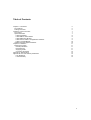
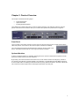
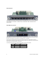
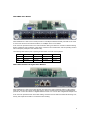
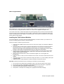
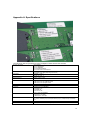
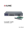
FriendlyNET™ FX4000
4-Slot Modular Switch
User’s Manual
2
Asanté FriendlyNET FX4000
Table of Contents
Chapter 1. Introduction
Key Features
Package Contents
Chapter 2. Product Overview
Front Panel
Optional Modules
FX40-8TP Module
FX40-2SMC15 Fiber Module
FX40-4MMC Fiber Module
FX40-1SX and FX40-1LX Gigabit Fiber Modules
FX40-1T Gigabit Module
Installing the FX40 Optional Modules
Chapter 3. Installation
Mounting the Switch
Desktop Installation
Rack Mounting
Supplying Power
Connecting the Switch
Appendix A. Specifications
Appendix B. FCC and Warranty Statements
FCC Statement
Limited Warranty
5
5
5
7
7
7
8
8
9
9
10
10
11
11
11
11
11
12
13
15
15
15
3
4
Asanté FriendlyNET FX4000
Chapter 1. Introduction
Thank you for purchasing the FriendlyNET FX4000. This switch combines Ethernet, Fast Ethernet and
Gigabit Ethernet capabilities in a single, rack mountable unit. Combining these interfaces allows the switch
to unclog existing LANs and to provide an efficient, high speed network. The switch features a store and
forward switching scheme. Every optional module has it’s own 12K entry MAC address table to store source
addresses. The backplane of the FX4000 can reach up to 9.6 Gbps, greatly improving network performance.
The FX4000 switch, with 4 optional modular slots, can accept many different media module combinations,
allowing you great flexibility in configuring your network.
Asanté offers the following types of modules:
• 8 Port 10/100BaseTX module
• 2 Port 100BaseFX Fiber module
• 4 Port 100BaseFX Fiber module
• 1000BaseSX/LX Fiber module
• 1000BaseT Gigabit copper module
Key Features
•
•
•
•
•
•
•
•
Conforms to IEEE 802.3, 802.3u, 802.3z, 802.3ab and 802.3x standards
4 expansion slots to configure a flexible network
Supports half duplex mode for backpressure, and full duplex for flow control
Store and forward switching architecture for abnormal packet filtering
Up to 9.6 Gbps backplane forwarding rate
12K entry MAC address table per module
3 to 5 MB memory buffer for modules
LED indicators for Power, Speed, Link, Activity, Full Duplex and Collision
Package Contents
Unpack the box of the FX4000 switch and verify the contents against the checklist below.
•
•
•
•
•
Switch
Power Cord
Rack mount Kit
Four Rubber Feet
User’s Manual (this document)
If any item is missing or damaged, please contact your local dealer immediately.
5
6
Asanté FriendlyNET FX4000
Chapter 2. Product Overview
This chapter contains the following topics:
•
•
•
Physical Description
Optional Modules
Installing Optional Modules
The FX4000 is a modular switch with four slots for optional modules. The LEDs are located on the front
panels of the switch and modules to allow you to monitor the operation and performance at a glance.
Front Panel
The front panel of the switch contains the Power LED, and the front panel of each module contains all the
LEDs and ports for connections to other devices (when modules are installed).
The 3 pronged power plug and On/Off switch are located on the rear panel of the
switch. The switch will work with AC in the range 100-240VAC, 50-60Hz.
Optional Modules
A variety of optional modules are available, allowing the user to choose modules that will optimize network
performance while reducing cost and complexity.
By providing 4 G-Link bus interfaces in the base unit, the user has the freedom to arrange any module in
any slot giving the ultimate in network flexibility. The integration of 10/100 Mbps and 1000 Mbps technology
is now a simple matter of installing the desired module. By mixing different modules in the same cabinet, the
user ensures that network performance and budget requirements are easily met.
7
FX40-8TP Module
When installed into the switch, this module provides 8 x 10/100 Mbps ports that can connect the switch to a
10 or 100 Mbps hub or end station. It utilizes 3 LED's to indicate status: 100M, Link/Activity and Full
Duplex/Collision.
FX40-2SMC15 Fiber Module
When installed into the switch, this module provides 2 x 100BaseFX fiber ports that can be used to connect
the switch to the backbone of the network, to a 100 Mbps server or end station.
A SC connector provides the link to the multi mode cabling and there are 2 LED indicators to show the
following status: Link/Activity and Full Duplex. A DIP switch, located on the module board, sets the operating
mode to half or full duplex (full duplex is the default).
The following table lists the ports’ operating modes based on the DIP switch position.
8
Port 1
Port 2
SW
1
2
ON
Half Duplex
Half Duplex
OFF
Full Duplex
Full Duplex
Asanté FriendlyNET FX4000
FX40-4MMC Fiber Module
When installed into a switch, this module provides 4 x 100 Mbps Fast Ethernet fiber ports that can be used
to connect the switch to the network backbone, a 100 Mbps server or end station.
A SC connector provides the link to the multi mode fiber cabling, and there are 2 LEDs to indicate following
status: Link/Activity and Full Duplex. A DIP switch, located on the module board, sets the operating mode to
half or full duplex (full duplex is the default mode).
The following table lists the ports’ operating modes based on the DIP switch position.
Port 1
Port 2
Port 3
Port 4
SW
1
2
3
4
ON
Half Duplex
Half Duplex
Half Duplex
Half Duplex
OFF
Full Duplex
Full Duplex
Full Duplex
Full Duplex
FX40-1SX and FX40-1LX Gigabit Fiber Modules
When installed into a switch, the FX40-1SX (50, 62.5/125 micron multi mode fiber optics to 2 Km) and the
FX40-1LX (8,9/125 micron single mode fiber optics to 60 Km) modules each provide one Gigabit Ethernet
port that can connect the switch to a Gigabit backbone switch or to a server with a Gigabit NIC adapter card.
A SC connector provides the link to the fiber cabling, and there are four LEDs to indicate the following: Link,
Activity, Full Duplex and Collision. The module is auto sensing.
9
FX40-1T Gigabit Module
When installed into a switch, the FX40-1T Gigabit module provides one Gigabit Ethernet port that can
connect the switch to a Gigabit backbone switch or to a server with a Gigabit NIC adapter card.
The module comes with a 10/100/1000 Mbps Nway autonegotiating RJ45 connector with automatic MDI
crossover function which provides the link to the switch. There are four LEDs to indicate the status of the
module: LK1000 (Green at 1000 Mbps), ACT (Blinking Green with Activity), LK100 (Green at 100 Mbps)
and FD (Yellow at Full Duplex),
Installing the FX40 Optional Modules
You can purchase any or all of the optional modules separately to meet the needs of your network. The
process of installing optional modules is described below.
Follow these steps to install the optional module:
1.
2.
3.
4.
5.
6.
7.
Power the switch OFF and disconnect it from the main power supply. The modules are NOT hotswappable
Place the switch on a flat surface. Grasp the thumbscrew on the sides of the optional module or
blank bracket and turn counter-clockwise to unscrew them. You can also use a screwdriver.
Remove the old module or the blank bracket and set aside. Do not discard the module or blank
bracket. Put the module or blank bracket back in if you remove the new module.
Install the new module by inserting it into the guides and sliding it in until it stops. Press it firmly
until you feel the module snap into place. Never force, twist or bend the optional module. The
optional module slides in smoothly.
Gently push the thumbscrews in and turn clockwise to tighten. Do not over tighten the
thumbscrews.
Power the switch on after you have installed the new module. The switch will auto detect the new
module.
Take off the dust cover from the transceiver and plug the cable in, if you are installing a fiber optic
or gigabit module.
Check the LEDs to verify that there is a link and a proper connection at the port.
Important! Follow the instructions below on handling the modules to prevent damage:
1.
2.
3.
4.
5.
10
Do not remove the module from its packaging until you are ready to install it into the switch.
Do not touch any of the components on the module other than the DIP switch, if applicable.
Touch the module only by its edges and front panel.
Always wear anti-static wristband connected to a suitable grounding point.
Always store or transport the module(s) in the appropriate anti-static packaging.
Asanté FriendlyNET FX4000
Chapter 3. Installation
This chapter describes the basic installation of the switch.
Mounting the Switch
The switch is suitable for use in an office environment where it can be rack mounted in standard EIA 19-inch
racks or it can stand alone.
Desktop Installation
1.
2.
3.
4.
5.
Set the switch on a sufficiently large, flat space with a power outlet nearby. The surface where you
put your switch should be clean, smooth, level, and sturdy.
Make sure there is enough clearance around the switch to allow attachment of cables and the
power cord, and to allow air circulation.
Make sure the bottom surface of the switch is free of grease and dust.
Remove the adhesive backing from the rubber feet.
Apply the rubber feet to each corner on the bottom of the switch. These footpads can prevent the
switch from slipping, shock and vibration.
Rack Mounting
The switch comes with a rack mount kit and can be mounted in an EIA standard size, 19-inch rack. The
switch can be placed in a wiring closet with other equipment.
Perform the following steps to rack mount the switch:
1.
2.
Position one bracket to align with the holes on one side of the switch and secure it with the bracket
screws. Then attach the remaining bracket to the other side of the switch.
After attaching both brackets, position the switch in the rack by lining up the holes in the brackets
with the appropriate holes on the rack. Secure the switch to the rack with a screwdriver and the
rack-mounting screws.
Note: For proper ventilation, allow at least 4 inches (10 cm) of clearance on the front and 3.4 inches (8 cm)
on the back of the switch. This is especially important for enclosed rack installations.
Supplying Power
To supply power to your switch:
1.
2.
3.
4.
Plug the power cord into the power port on the rear panel of the switch.
Plug the other end of the power cord into an AC wall outlet.
Turn the power switch to ON and verify that the Power LED is lit. If not check that the power cord is
properly connected, the power switch is ON and that the outlet is functional.
Connect the network cables. See the following section for the recommended cable types.
Note: Network cables can be connected or disconnected while the switch is on.
11
Connecting the Switch
You can connect your switch to network devices, such as desktops, workgroups or to other hubs. Before
connecting to a desktop or workgroup, ensure that the following cabling requirements are met:
1.
2.
3.
4.
12
The 10BaseT Ethernet cable is Category 3 or better UTP cabling.
The 100BaseTX Fast Ethernet and 1000BaseT cable is tested Category 5 or better UTP cabling.
The 100BaseFX fiber cable is 62.5/125 micron multimode fiber, or 9/125 micron single mode fiber.
The 1000BaseSX/LX fiber cable is 50/125, 62.5/125 micron multimode or 9/125 micron single
mode fiber.
Asanté FriendlyNET FX4000
Appendix A. Specifications
The table below lists the specifications of the FriendlyNET FX4000 and the FX40 modules.
Standards Compliance
Power
Temperature
Humidity
Switch Dimensions
Data Buffer
Address Table
Technology
Connectors
Transfer Rates
LED Indicators
EMI & Safety
Limited Warranty
802.3 10BaseT
802.3u 100BaseTX/FX
802.3z 1000BaseSX
802.3ab Gigabit 1000BaseT
802.3x Flow Control and Backpressure
100-240VAC 50/60Hz
Consumption: 30-42 Watts (depending on the module)
Operating: 0° to 45° C
Storage: -40° to 70° C
10% to 90% RH
440mm x 225mm x 66mm
19-inch Rack-mounted EIA standard
5 MB memory share per 10/100BaseTX module
5 MB memory share per 100BaseFX module
3 MB memory share per Gigabit module
12K entry MAC Address table per module
Store and Forward
FX40-8TP: RJ-45 Auto MDI/MDIX
FX40-2SMC15: SC
FX40-4MMC: SC
FX40-1SX/1LX: SC
FX40-1T: RJ-45 Auto MDI/MDIX
14,880 pps for 10 Mbps
148,800 pps for 100 Mbps
1,488,000 pps for 1000 Mbps
Per unit: Power LED
Per module: Link/Activity per port; Full-Duplex/Collision per port; 10 Mbps LED per 10/100 Mbps
port
FCC Class A, CE, UL and cUL
2 years (see statement in the following section)
13
14
Asanté FriendlyNET FX4000
Appendix B. FCC and Warranty Statements
FCC Statement
This equipment has been tested and found to comply with the limits for a Class A digital device, pursuant to
part 15 of the FCC Rules. These limits are designed to pro-vide reasonable protection against harmful
interference when the equipment is operated in a commercial environment. This equipment generates, uses,
and can radiate radio frequency energy and, if not installed and used in accordance with the instruction
manual, may cause harmful interference to radio communications. Operation of this equipment in a
residential area is likely to cause harmful interference in which case the user will be required to correct the
interference at his own expense.
Limited Warranty
Subject to the limitations and exclusions below, Asanté warrants to the original end user purchaser that the
covered products will be free from defects in title, materials and manufacturing workmanship for a period of
two years from the date of purchase. This warranty excludes fans, power supplies, non-integrated software
and accessories. Asanté warrants that the fans and power supplies will be free from defects in title,
materials and manufacturing workmanship for two years from date of purchase. Asanté warrants that nonintegrated software included with its products will be free from defects in title, materials, and workmanship
for a period of 90 days from date of purchase, and the Company will support such software for the purpose
for which it was intended for a period of 90 days from the date of purchase. This warranty expressly
excludes problems arising due to compatibility with other vendors’ products, or future compatibility due to
third party software or driver updates.
To take advantage of this warranty, you must contact Asanté for a return materials authorization (RMA)
number. The RMA number must be clearly written on the outside of the returned package. Product must be
sent to Asanté postage paid. In the event of a defect, Asanté will repair or replace defective product or
components with new, refurbished or equivalent product or components as deemed appropriate by Asanté.
The foregoing is your sole remedy, and Asanté's only obligation, with respect to any defect or nonconformity. Asanté makes no warranty with respect to accessories (including but not limited to cables,
brackets and fasteners) included with the covered product, nor to any discontinued product, i.e., product
purchased more than thirty days after Asanté has removed such product from its price list or discontinued
shipments of such product.
This warranty is exclusive and is limited to the original end user purchaser only. This warranty shall not apply
to secondhand products or to products that have been subjected to abuse, misuse, abnormal electrical or
environmental conditions, or any condition other than what can be considered normal use.
ASANTÉ MAKES NO OTHER WARRANTIES, EXPRESS, IMPLIED OR OTHERWISE, REGARDING THE
ASANTÉ PRODUCTS, EXCEPT TO THE EXTENT PROHIBITED BY APPLICABLE LAW, ALL
WARRANTIES OR CONDITIONS OF MERCHANTABILITY OR FITNESS FOR A PARTICULAR PURPOSE
ARE HEREBY DISCLAIMED. ASANTÉ'S LIABILITY ARISING FROM OR RELATING TO THE PURCHASE,
USE OR INABILITY TO USE THE PRODUCTS IS LIMITED TO A REFUND OF THE PURCHASE PRICE
PAID. IN NO EVENT WILL ASANTÉ BE LIABLE FOR INDIRECT, SPECIAL, INCIDENTAL, OR
CONSEQUENTIAL DAMAGES FOR THE BREACH OF ANY EXPRESS OR IMPLIED WARRANTY,
INCLUDING ECONOMIC LOSS, DAMAGE TO PROPERTY AND, TO THE EXTENT PERMITTED BY LAW,
DAMAGES FOR PERSONAL INJURY, HOWEVER CAUSED AND ON ANY THEORY OF LIABILITY
(INCLUDING NEGLIGENCE). THESE LIMITATIONS SHALL APPLY EVEN IF ASANTE HAS BEEN
ADVISED OF THE POSSIBILITY OF SUCH DAMAGES OR IF THIS WARRANTY IS FOUND TO FAIL OF
ITS ESSENTIAL PURPOSE.
Some jurisdictions do not allow the exclusion or limitation of incidental or consequential damages or
limitations on how long an implied warranty lasts, so the above limitations or exclusions may not apply to
you. This warranty gives you specific legal rights, and you may have other rights, which vary from jurisdiction
to jurisdiction.
15
FriendlyNET FX4000
4-Slot Unmanaged Switch
User’s Manual
Asanté Technologies, Inc.
821 Fox Lane
San Jose, CA 95131
USA
SALES
800-662-9686 Home/Office Solutions
800-303-9121 Enterprise Solutions
408-435-8388
TECHNICAL SUPPORT
801-566-8991: Worldwide
801-303-3787: FAX
www.asante.com
[email protected]
Copyright © 2002 Asanté Technologies, Inc. All rights reserved. No part of this document, or any associated artwork,
product design, or design concept may be copied or reproduced in whole or in part by any means without the express
written consent of Asanté Technologies, Inc. Asanté is a registered trademark and the Asanté logo and FriendlyNET are
trademarks of Asanté Technologies, Inc. All other brand names or product names are trademarks or registered
trademarks of their respective holders. All features and specifications are subject to change without prior notice.
06-00643-00 Rev. A
16
Asanté FriendlyNET FX4000