1
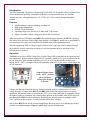
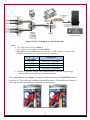
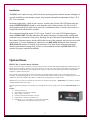
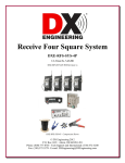
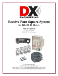
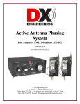
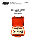
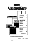
2-Port Receiving Antenna Switch RLS-2 DXE-RLS-2-INS Revision 3 © DX Engineering 2011 P.O. Box 1491 ∙ Akron, OH 44309-1491 Phone: (800) 777-0703 ∙ Tech Support and International: (330) 572-3200 Fax: (330) 572-3279 ∙ E-mail: [email protected] Introduction The DX Engineering 2-Port Receiving Antenna Switch RLS-2 is designed to allow selection of one of two output ports (generally connected to different receiving antennas) from one feedline. Transfer activates with application of a +10-15 Vdc or 9-12 Vac control voltage through the feedline. Features Metal housing for superior shielding and long life High quality components Reliable F-type connectors Operating range from 300 kHz to 30 MHz with 75 Ω systems Jumper-selectable, control voltage pass-thru to the selected port When used with two DX Engineering RBS-1 Reversible Beverage Systems, the RLS-2 will allow selection of four directions using a single main feedline. See Figure 1. Install one or more RLS-2’s to expand larger Beverage arrays and share the feedline back to the operating position. The DX Engineering FVC-1 Voltage Coupler can be used to supply the control voltages through the feedline to control 4-direction switching of a receiving antenna array or selection of four different receive antennas. Operation The RLS-2 is in effect a SPDT (Single Pole, Double-Throw) RF switch that has one input port and two output ports. With no control voltage, the NC (normally closed) ANT 1 port is connected to the RCVR input port. With constant application of +12 Vdc or 12 Vac through the feedline ports switch, the NC ANT 1 port opens and the NO (normally open) ANT 2 port closes, connecting to the RCVR input port. Jumper Header shown in the “OFF” position. (factory default) Voltage pass through is blocked. Voltage pass through is blocked (Factory Default) when the jumper is show as above. To pass voltage through, to control other RLS-2s, the RBS-1 Reversible Beverage System, or a special application, the internal jumper is moved to the “ON” (pin in center and right are jumpered). When the right two pins are connected, any control voltage present on the feedline at the RCVR port will pass through the RLS-2 to the selected port. Removing the internal jumper (or putting it on the “OFF” position as shown above - Factory Default) blocks these voltages. One or more RLS-2s can also be used to expand larger Beverage arrays or for placing taps along a feedline for multiple antennas. Figures 1 and 2 depict typical configurations. 2 Figure 1: RLS-2 Used with Two RBS-1 Reversible Beverage Systems Notes: Uses single coax run from each DXE-RBS-1FP Uses voltage on the feedline to switch the DXE-RLS-2 and the DXE-RBS-1FP DXE-RLS-2 switches when +12 Vdc is applied to feedline, DXE-RBS-1FP switches when −12 Vdc is applied giving port selection per table below Voltage Applied to Feedline 0 Vdc -12 Vdc +12 Vdc 12 Vac Selected Port Beverage A, Away Beverage A, Toward Beverage B, Away Beverage B, Toward The DXE-FVC-1 applies the voltages to the feedline and can be controlled using BCD logic with the CC-8A or a switch closure to ground arrangement 3 Figure 2: RLS-2 Configured to Switch 4 Antennas Notes: Uses single coax run from each RLS-2 Uses voltage on the feedline to switch the RLS-2s RLS-2M is a converted RLS-2 that switches when −12 Vdc is applied to feedline, other RLS-2s switch normally, giving port selection per table below Voltage Applied to Feedline 0 Vdc +12 Vdc -12 Vdc 12 Vac Selected Port Ant Array 1, Segment A Ant Array 1, Segment B Ant Array 2, Segment C Ant Array 2, Segment D The FVC-1 applies the voltages to the feedline and can be controlled using BCD logic with the CC-8A or a switch closure to ground arrangement The configuration shown in Figure 2 requires a modification to one of the DXE-RLS-2 units to operate at -12 Vdc to allow the switching functions shown above. The modification consists of removing one diode and installing it backwards as shown below. D1 Diode Normal and Reversed 4 Installation The RLS-2 can be placed at any point between the operating position and the antenna, although it is typically installed near the antenna systems. Any location with ambient temperatures below 150° F (65° C) is acceptable. In outdoor applications, a bead of non-corrosive, marine grade silicone, like DX Engineering part number DXE-RTV598335, should be used along the seams of the enclosure. Be sure to leave a small opening in the bead, at the lowest point, for a condensation drain. Corrosive silicones have a vinegar-like smell and should be avoided. We recommend using high quality 75 Ω F-6 type “flooded” coax such as DX Engineering part number DXE-F6-SPL. Flooded cables have the distinct advantage of automatically sealing small accidental cuts or lacerations of the jacket. Flooding also prevents shield contamination and can be direct-buried. Moisture ingress into the shield often occurs at the connector and can cause increased system noise. To ensure weatherproof connections, use DXE-SNS6-25 Snap-N-Seal connectors. (DXE-SNS6-25 contains 25 Snap-N-Seal connectors). The Snap-N-Seal connectors cannot be installed with normal crimping tools or pliers, so an installation tool like the DXE-SNS-CT1 is essential for proper connector installation. Optional Items DXE-CC-8A - Control Console, 8 Position The CC-8A Control Console is a flexible, 8-position controller used to control the DX Engineering RR8 series antenna switches, the RFS-2P Receive Four Square controller or any product that uses a 12 or 24* Vdc 1-of-8 or BCD control format. The attractive metal housing is powder-coated and features an ON/OFF switch, ergonomic selector knob and eight front-panel LED's, with adjustable brightness, to indicate switch position. The rear panel external plug allows the control cable to be easily unplugged during weather events or if the shack needs to be rearranged. We suggest unplugging the CC-8A control leads when severe weather is expected. The use of a lightning protector on the control lines, such as the PolyPhaser PPC-IS-RCT, available from DX Engineering, is prudent as well. Shielded CAT-5 type cable can be used for the control cable. (8 conductors plus ground). stranded, shielded cable for best results. DXE-CW9S is a top quality 9-conductor For most applications requiring 12 vdc switching, your existing transceiver power supply or the accessory DXE-PSW-12D1A can be used. Features Switching positions: 8 Input voltage: 12/24 Vdc, user supplied Output voltage: 12/24 Vdc * Protection: Dual internal automatic reset fuses Output format: 3-bit BCD or standard 1-of-8 Dimensions: 8 x 5 x 2.75'' (203.2 x 127 x 69.85 mm) (WxDxH) *Dependent on user-supplied dc input power source. 5 DXE-FVC-1 - Feedpoint Voltage Coupler The FVC-1 provides an interface for standard control switches, such as the DXE-CC-8A or your own arrangement to voltagemultiplexed antenna systems. This interface system will provide the voltages required to remotely select up to four antennas (or four directions) through receiving or low power transmitting feedlines. It provides fuse-protected 0V, +12 Vdc, -12 Vdc, and 12 Vac. output voltages through a panel mounted feedline connector. These voltages can be used to provide four-direction switching of an antenna array either through the feedline or on a single wire supplemental control line. Control is done using a standard 1 of 4, BCD or switch closure interface. The FVC-1 is recommended for use with the DX Engineering RFS-2P Remote Four-Square Antenna System , the RBS-1 Reversible Beverage Antenna System, and the RLS-2 Transfer Switch.. The CC-8A Control Console can provide the 1 of 4 and BCD input used by the FVC-1 or you can use your own switch. The FVC-1 also has two LED indicators, red and green, which indicate the presence and polarity of the output control voltage being used. They are directional indicators that can be read at a convenient distance and can aid in troubleshooting. Features Safe, external 12V heavy duty power pack. Metal Housing – superior shielding, rugged, and easy mounting Convenient installation– mounts anywhere in your shack Rugged Control Connector – reliable solder-less connections Internal thermal reset fuse- full protection against accidental shorts Flexible logic input- BCD or standard one-of-four, high or low actuated Operation indicators- bright red and green LED indicators can be seen at a distance DXE-RBS-1P - Reversible Beverage Antenna System - Two Direction New, improved RF Shielded packaging! The RBSA-1P allows two Beverage antennas receiving in opposing directions to share the same space. With the RBSA-1P, build a 2-wire reversible Beverage antenna system with superior directivity and signal-to-noise ratio, most useful on the 160, 80 and 40m bands. The W8JI design consists of a Feedpoint Unit and a Reflection Transformer. Use two RBSA-1P's with a DX Engineering RLS-2 switch and have four-direction switching using a single feedline. This system is immune to strong signal overload and core saturation common in multi-transmitter contesting environments, and is used by winning contest stations and low-band DXers. As an recommended accessory, the DXE-RPA-1 preamp utilizes a push-pull amplifier design and robust components enable it to withstand high signal levels. The dynamic range of the RPA-1 is better than most receivers. It can actually provide a high level of protection against high RF levels and ESD for many transceivers with unswitched, unprotected receive antennna inputs! The RBSA-1P has two antenna ports. The standard configuration of the RBSA-1P has one port terminated (termination included) so both antennas share a common feedline. Applying negative 10 to 18 Vdc to the feedline switches between the antennas, and the direction of reception. For simultaneous reception from opposing directions, each of the two feedlines can be run to separate receivers. While the RBSA-1P is optimized to use 450 Ω ladder line for the antenna element, the system will work with any 300-600 Ω two-wire line. 450 Ω ladder line as well as high quality "flooded" 75 Ω coax and F type connectors , to ensure a weather-tight installation, are available from DX Engineering and are sold separately. Broad operating range, 0.2 to 30 MHz - Fully isolated grounds prevent common-mode noise and unwanted signals - 75 Ω design enables the use of high quality, low cost cable and connectors - RF Shielded housing used for isolation and improved life DXE-RFCC-1 - Receive Feedline Current Choke, 50 to 75 Ohm 300 kHz to 30 MHz If you wish to reduce feedline radiation and improve reception, a Feedline Current Choke is recommended if your SWR is already low. Adding a DX Engineering Feedline Current Choke at the point where the feedline exits the area of the antenna will substantially reduce unwanted feedline radiation or reception without the need for improved station grounding. The advantages of using an FCC: Prevents unwanted RFI by eliminating feedline current and radiation All power goes to the antenna, improving efficiency Reduces noise or unwanted signals picked-up by the feedline Overcome a less than optimal ground system The DX Engineering RFCC-1 receive feedline common-mode choke is the most effective solution to common-mode noise or unwanted signal ingress available to date. The DX Engineering RFCC provides thousands of ohms isolation between the input and output coaxial shield connections while passing desired signals, including dc or low frequency ac control signals. The RFCC has extremely high isolation impedance which effectively blocks common-mode noise or unwanted signals, even in the presence of very poor grounding. Low noise receive antennas are traditionally located away from electrical wiring and other noise sources. Unfortunately, noise and other unwanted signals have a direct path to your low-noise antenna through the feedline shield connections between the station equipment and antenna. Unwanted signals can also energize the outside of the feedline shield, and this undesired signal energy can be conducted directly to the receiving antenna. This can reduce antenna directivity. Unless you have a perfect zeroresistance RF ground at the antenna, some of the common-mode noise or unwanted signals from the feedline shield will make it into the antenna. The RFCC is effective from 300 kHz to 30 MHz. It comes with standard CATV type “F” female connectors, although it can be used in any 50 to 75 ohm receiving system. The RFCC is a passive device, therefore requires no power to operate. 6 DXE-RPA-1 - Receiver Preamplifier, 0.3-35 MHz This is the best HF low noise amplifier available. The RPA-1 is optimized for 0.3-35 MHz operating range. The push-pull amplifier design and robust components enable it to withstand high signal levels and operate when you need it most. The dynamic range of the RPA-1 is better than most receivers. The RPA-1 is suitable for indoor or outdoor installation, with the option of being powered through the coaxial feed. The metal housing provides shielding and improved lifespan. The unit uses RCA type phono jack and CATV F connector for the input and output connections, and has a relay that automatically bypasses the amplifier when dc power is removed. Benefits: Push-pull operation eliminates harmonic distortion High quiescent current increases ability to handle strong signals without distortion or overload Meticulous craftsmanship and durable components provide superior dynamic range RCA type phono jack and type F connector ease installation Simplified switching - automatic bypass eliminates gain when dc power is off 10-18 Vdc power using power connector or through the coax 10-18 Vdc through coax enables remote operation at antenna DXE-F6 - 75 Ohm F-6 Style, Direct Bury Coaxial Cable: Full Spool or Custom Cable Assemblies DX Engineering recommends using a high quality 75 Ω “flooded” F6 type coaxial cable. Flooded style cables have the distinct advantage of automatically sealing small accidental cuts or lacerations of the jacket. Flooding also prevents shield contamination and can be direct-buried. This low-loss cable features dual shields and an 85% Velocity Factor.. Custom cable assemblies are available, Call DX Engineering for details. DXE-SNS6 Snap-N-Seal connectors are recommended for use with this coaxial cable to ensure a high quality and weather resistant feedline connection. The proper tool DXE-SNS-CT1 must be used to install these connectors. DXE-CPT-659 - Coax Cable Stripper for CATV F-6, RG-6 and RG-59 coax Prepares CATV F-6, RG-6 and RG-59 coax cable for the installation of an "F" type connector. One-step cutting motion - Precision cut - No nicks or scratches to conductor - Includes 1 replacement blade DXE-SNS6-25 - Watertight Coaxial Connector, Snap-N-Seal for CATV F-6 Cable, 25 pieces Snap-N-Seal is an environmentally sealed CATV F coaxial connector system for harsh environments. The connectors have a unique, 360 degree radial compression system that offers the signal leakage protection required for high performance receive systems. Quad sealed system prevents moisture from migrating into the connection 360 degree radial compression provides superior RF integrity (-95dB typical, 60% bonded foil cable) Easy cable preparation Connector to cable retention of 40 lbs minimum Superb impedance match to 1 GHz Manufactured of high quality 360 brass, cadmium plated with yellow chromate coating for maximum corrosion resistance UV-resistant plastic and O-rings provide a reliable environmentally sealed connector An installation tool, such as the DXE-SNS-CT1 is required to install the connectors. Normal crimping tools or pliers will not work. DXE-RTV598335 - DX Engineering Approved RTV Sealant Permatex Black RTV Sealant, Non-Acetic. We have all used RTV to seal water out of things, right? Have you ever sealed a piece of electronic gear with it -- then opened it some time later to find that it had still managed to become corroded inside? Guess what? It's not the rain that corroded it - It's the RTV! Normal RTV gives off acetic acid when it cures. That's the vinegar smell. The acetic acid causes the corrosion. Applies just like "normal" RTV, dries in one hour and cures in 24 hours at 70 degrees F. And it doesn't smell like vinegar! 3.3 oz. Tube - Black *This part is classified hazardous and is limited to domestic UPS Ground shipping only DXE-SNS-CT1 - Compression Tool for Snap-N-Seal 75 Ohm Coaxial Connectors Ratchet compression tool for installing DXE-SNS6 Snap-N-Seal coaxial connectors. Ordinary pliers will not install these connectors properly. 7 DXE-CW9-1K - Shielded Control Wire, 9 conductor, 1000 ft reel DXE-CW9 - Shielded Control Wire, 9 conductor, per foot DXE-CW9-1K is a 1000 foot box of high quality shielded outdoor FTP (Foil Twisted Pair) Cat5e cable. It features 4 Twisted pairs of 24 AWG solid wire with Al foil shielding plus a solid tinned copper drain wire - providing a total of 9 conductors for DC switching applications. It has a polyethylene jacket and is rated for direct burial. This cable is ideal for DX Engineering Remote Antenna Switches and Four Square arrays, and should be considered for any low-current custom remote switching application you have - such as receiving antenna arrays. A nice feature is the "rip cord", which allows for easy stripping of the heavy jacket without worry about nicking or accidentally cutting the conductors. Excellent for use in all outdoor applications of switching, networking, data transfer and phone lines. As a data transfer line, it supports 10/100/1000Mbps. DXE-LL450-1K - Ladder Line, 450 ohm - 1000 ft. Spool DXE-LL450-5C - Ladder Line, 450 ohm - 500 ft. Spool Transmit-quality 450 ohm ladder line for your antenna project when the feedpoint impedance is close to 400 Ohms. It is also ideally suited for use with our Reversible Beverage Antenna, the RBS-1P. This quality line is constructed of 16 gauge conductors that are formed by 19 strands of 29 gauge copper-clad steel wire which provides the strength to hold up for long runs between supports. Actual impedance is nominally 40 0 Ohms with a nominal velocity factor of 91%. 1000' or 500' Spool - Conductor AWG(strand): 16 (19/29) - Nominal Impedance: 400 Ohms - Velocity factor of 91% Technical Support If you have questions about this product, or if you experience difficulties during the installation, contact DX Engineering at (330) 572-3200. You can also e-mail us at: [email protected] For best service, please take a few minutes to review this manual before you call. This unit is RoHS (Reduction of Hazardous Substances) compliant. The components, including the solder used are all lead free. If you decide to do any modifications or internal repairs, you should use only lead free solder and lead free soldering tools. Lead free solder melts approximately 100 degrees higher than the old leaded solder, so you may need to upgrade your current soldering system. Warranty All products manufactured by DX Engineering are warranted to be free from defects in material and workmanship for a period of one (1) year from date of shipment. DX Engineering’s sole obligation under these warranties shall be to issue credit, repair or replace any item or part thereof which is proved to be other than as warranted; no allowance shall be made for any labor charges of Buyer for replacement of parts, adjustment or repairs, or any other work, unless such charges are authorized in advance by DX Engineering. If DX Engineering’s products are claimed to be defective in material or workmanship, DX Engineering shall, upon prompt notice thereof, issue shipping instructions for return to DX Engineering (transportationcharges prepaid by Buyer). Every such claim for breach of these warranties shall be deemed to be waived by Buyer unless made in writing. The above warranties shall not extend to any products or parts thereof which have been subjected to any misuse or neglect, damaged by accident, rendered defective by reason of improper installation, damaged from severe weather including floods, or abnormal environmental conditions such as prolonged exposure to corrosives or power surges, or by the performance of repairs or alterations outside of our plant, and shall not apply to any goods or parts thereof furnished by Buyer or acquired from others at Buyer’s specifications. In addition, DX Engineering’s warranties do not extend to other equipment and parts manufactured by others except to the extent of the original manufacturer’s warranty to DX Engineering. The obligations under the foregoing warranties are limited to the precise terms thereof. These warranties provide exclusive remedies, expressly in lieu of all other remedies including claims for special or consequential damages. SELLER NEITHER MAKES NOR ASSUMES ANY OTHER WARRANTY WHATSOEVER, WHETHER EXPRESS, STATUTORY, OR IMPLIED, INCLUDING WARRANTIES OF MERCHANTABILITY AND FITNESS, AND NO PERSON IS AUTHORIZED TO ASSUME FOR DX ENGINEERING ANY OBLIGATION OR LIABILITY NOT STRICTLY IN ACCORDANCE WITH THE FOREGOING. ©DX Engineering 2011 DX Engineering®, DXE®, Hot Rodz™, Maxi-Core™, THUNDERBOLT™, Antenna Designer™, Yagi Mechanical™, and Gorilla Grip® Stainless Steel Boom Clamps, are trademarks of PDS Electronics, Inc. No license to use or reproduce any of these trademarks or other trademarks is given or implied. All other brands and product names are the trademarks of their respective owners. Specifications subject to change without notice. 8