1
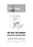
INSTALLATION NOTES
Cannon
DON’T RISK YOUR APPLIANCE WARRANTY
ONLY A LICENSED PERSON WILL GIVE YOU A COMPIANCE
CERTIFICATE, SHOWING THAT THE WORK COMPLIES WITH
ALL THE RELEVANT STANDARDS.
FITZROY INBUILT
AND ONLY A LICENSED PERSON WILL HAVE INSURANCE
PROTECTING THEIR WORKMANSHIP FOR 6 YEARS.
SO MAKE SURE YOU USE A LICENSED PERSON TO INSTALL
THIS APPLIANCE AND ASK FOR YOUR COMPLIANCE
CERTIFICATE TO ENSURE THE MANUFACTURERS
APPLIANCE WARRANTY WILL BE HONOURED.
OPERATION INSTRUCTIONS
Power Flue
INSTALLATION INSTRUCTIONS
SERVICE INSTRUCTIONS
COPY RATING LABEL HERE
Date installed: ...............................................................................................
Installed by: ...................................................................................................
Compliance Certificate No .............................................................................
PLEASE READ THIS MANUAL
BEFORE INSTALLING
THIS HEATER.
For service to this appliance or spare
parts contact the CANNON distributor:
Sampford IXL (spare parts)
Phone: 1300 727 421
Fax: 1300 727 425
email: [email protected]
28
Cannon
FITZROY INBUILT
Power Flue
Part No: F3045
Revision P - 2010
Gmk10030
AS4553:2008
This heater is approved for use with
Natural and Propane gases.
Please leave instructions with the owner
CONTENTS
NOTES
Contents
2
Warranty
? Distributor
Heater specifications
3
Safety warnings
? What to do if you smell gas
? Warnings
? Standards
? Regulatory location
User instructions
? Operating instructions
? Cleaning
? Flame characteristics
Installation instructions
?
?
?
?
?
?
?
4
5-6
7
8-9
10 -13
Clearances
Fitment of cabinet depth spacer
Flueing options
Fitment of flue cowl
Preparing flexible flue pipes
Front fascia removal
Sealing the fascia
Electrical Connection
Gas connections
Log installation
Gas control
16
16
17
18-19
? Gas pressure point
? Gas pressure adjustment
?
Trouble-shooting
20-21
Service instructions
22-24
?
?
?
?
?
?
?
?
?
?
?
?
?
2
General
To replace the primary glass
To replace outer glass
To replace the gas control
To replace the ignition (module) device
To replace the room circulation fan
To replace the fan pressure switch
To replace the burner and spark/sense electrode
To replace the combustion fan
Wiring diagram
Data plate
Date installed, Compliance Certificate No.
For service to this appliance
27
NOTES
WARRANTY
The benefit conferred by this warranty are in addition to all other rights and
remedies in respect of the product that consumers have under the Trade
Practices Act and similar laws of the States and Territories.
We warrant this Cannon appliance to be free of defects in materials,
workmanship and manufacturing to the original purchaser for 2 years, (10 years
on the heat exchanger) from the date of original purchase. We will, at our
option and subject to the terms of this warranty, repair or replace free of charge
this Cannon appliance or any component part, which upon examination by us
or our repair agent is found to be defective in materials, workmanship or
manufacturing. However, this warranty does not cover any consumables (if any).
The purchaser must present the original purchase receipt to us when making
any claim under this warranty.
This warranty will not apply if: (i) a compliance label or serial number (as the
case may be) has been removed from the appliance or rendered illegible; (ii)
the appliance has been subject to misuse, abuse, accident, incorrect installation
or non-domestic use; (iii) the appliance has been modified, tampered with or
repaired by a person other than our authorised repair agent; (iv) the appliance
is re-installed/relocated during the warranty period.
The purchaser is responsible for all travelling expenses if the purchaser
requests any repair be carried out at a place outside areas normally serviced
by our repair agents.
Should you require service on this appliance, please contact our service
department on 1300 727 421.
Enter the details of the date installed and the Compliance Certificate number in
the appropriate area on the rear page of this manual.
Don’t risk your appliance warranty
Only a licensed person will give you a Compliance Certificate,
showing that the work complies with all the relevant standards.
And only a licensed person will have insurance protecting their
workmanship for 6 years.
So make sure you use a licensed person to install this appliance
and ask for your Compliance Certificate to ensure the manufacturers appliance warranty will be honoured.
Distributor
This appliance is designed, manufactured and distributed by:
26
Tel: 1300 727 421
3
YELLOW/GREEN
BLUE
COILS
ROOM FAN - F3594
WHITE
BROWN
BLUE
BLK
W
BRN
BROWN
RED
BLACK
PURPLE
GREY
FUSE 1.5 AMP
BLUE
240 V MAINS PLUG
POWER FLUE
WIRING DIAGRAM F3663-6_B
RED
BLUE
YELLOW/GREEN
E N A
PRESSURE
SWITCH F3327
ROOM AIR FAN
NO
NO
COMMON
IGNITION MODULE
F3435
4 WAY
SPARK
ELECTRODE
FLAME
SENSOR
PRESSURE
SWITCH F3327
COMBUSTION FAN
MODULATING
VALVE F3691
COMBUSTION
FAN - F3659
4 WAY
COMMON
ORANGE
FIG 1.
BLACK
N
N
BROWN
GREY
PURPLE
ORANGE
RED
BLUE
BLUE
A
L
M
FUNCTION
CONTROL
MODULE
P/No. F3604
H
TH2
MOD1
MOD2
WHITE
BLACK
HIGH BRN / HIGH FAN
SWITCH
ON/OFF
MED BRN / MED FAN
WHITE
6 WAY CONNECTOR
LW BRN / LW FAN
8 WAY CONNECTOR
Optional accessories:
Glass front
Remote thermostat
Spacer kit
3 sided surround
4 sided surround
Console kit
4
6 WAY CONNECTOR
Gas type:Natural or Propane gas, as indicated on data label
Gas consumption:
26.0 MJ/hr
Energy output:
5.98 kW
Enery star rating:
5.05 stars
Heater type:
Gas space heater
approved to AS 4553:2008
Operating pressure:
Natural gas: 0.75 kPa
(at burner high setting)
Propane gas: 2.65kPa
Gas regulator:
Integral part of controller
Min. inlet pressure:
1.13 kPa (NG)
2.75 kPa (Propane)
Fan:
3 speed
Controller:
Electronic direct spark
Power requirement:
240 VAC 10 A
Power consumption:
90 VA maximum
Minimum cavity Height:
605 mm*
*(FOR INSTALLATION INTO A
dimensions:Width:
700 mm
MASONRY/BRICK FIREPLACE)
Depth:
485 mm
SHEATHED
CABLE
WIRING DIAGRAM
HEATER SPECIFICATIONS
25
SERVICE INSTRUCTIONS
notes
SAFETY WARNINGS
Please read this manual before installing and using the heater.
TO REMOVE THE BURNER
AND ELECTRODES
1.
2.
3.
4.
5.
6.
7.
8.
9.
10.
11.
TO REPLACE THE
COMBUSTION FAN
Remove the front mesh cover.
Slacken off the glass clamp screws and remove the
top and one side clamp.
Follow fig 25. of the installation instructions
for glass removal.
Remove the logs from the burner chamber.
Remove the inspection hatch cover.
Disconnect supply pipe nut from the burner manifold.
Remove the electrode connections from the spark
module.
Release gland seal retaining nut.
Remove burner fixing brackets (2) from rh and lh
sides of the burner. lift the burner assembly upwards
and carefully remove from the burner chamber.
Pull electrode leads from the gland seal.
Replace in reverse order.
The Combustion Fan is accessed from the rear of the heater.
Therefore to replace the combustion fan the heater must be
removed from the fireplace. The flue terminal may need to be
removed from the flue hoses to allow the heater to be moved.
1. Disconnect combustion fan wiring from loom.
2. Remove the rear cover.
3. Remove the four (4) screws securing the fan to fan duct.
4. Remove fan assembly from fan duct.
5. Replace in reverse to disassembly.
FIG 31.
What to do if you smell gas
1. Turn OFF the main gas supply.
2. Extinguish any open flame.
3. Open windows.
4. Do not touch electrical switches.
5. Do not use your telephone.
6. Call your gas supplier immediately from a neighbour’s phone.
Warnings
1. Improper installation, adjustment, alteration, service or maintenance can cause
injury or property damage. Refer to the sections of this manual for correct
procedures, or consult with place of purchase, a licensed plumber, a gas supplier
or the CANNON distributor listed in this manual.
2. Install the heater only in locations that are referred to in the installation instructions.
Do not build the heater into bookcases, walls or enclosures without the use of a
Mock Fireplace kit if appropriate for that type of installation.
3. Due to high temperatures the room heater should be located out of traffic and away
from:
Furniture and draperies
Combustible materials
Gasoline and other flammable liquids
Do not place clothing or other flammable material on or near the heater.
4. Keep curtains*, clothes, furniture and other flammable materials at least
900mm from front and sides of heater.
* At the owner’s discretion curtain clearance can be less than 900mm as
long as they are restrained from the front, top and sides of the heater. The
manufacturer takes no responsibility if curtain clearance is less than 900mm
and not restrained.
5. Children and adults should be alerted to the hazard of high surface temperature
and should take care to avoid burns or clothing ignition.
This appliance is not intended for use by persons (including children) with reduced
physical, sensory or mental capabilities or lack of experience and knowledge,
unless they have been given supervision or instruction concerning use of the
appliance by a person responsible for their safety.
Children should be supervised to ensure that they do not play with the appliance.
6. Never attempt to burn paper or any other material in the heater.
TO REPLACE TYPE “X”
CORD
24
1. CONTACT SAMPFORDIXL SERVICE DEPARTMENT AND QUOTE CORD
PART NUMBER F2799.
7. Do not place articles on or against this appliance.
Do not use or store flammable materials near this appliance.
Do not spray aerosols in the vicinity of this appliance while it is in operation.
Do not modify this appliance.
5
SAFETY WARNINGS
8.
If removed, the glass window must be put back onto the unit prior to operating the
heater.
9.
Installation and repairs should be performed by a licensed service person only,
refer to back of the instructions for service number.
10. For installation into a non-combustible fireplace, i.e.: masonry or brick or into a
mock fireplace, i.e. timber or plasterboard, the chimney and base should be of
sound construction and be free from cracks and holes (to ensure that sufficient
flue draught can be generated).
Note: When installing into a mock fireplace a mock fireplace installation kit
must be used.
11. The heater must be properly installed in a working chimney or connected to a
venting system. Operation of this heater, when not connected into a working
chimney or a properly installed and maintained venting system can result in
carbon monoxide (CO) poisoning and possible death.
12. Testing the effectiveness of the flue.
Before testing the flue confirm air vents are unobstructed. If an exhaust fan or
other heating appliances are present switch them on. This is to test that there is
no interaction between the Cannon heater and other appliances.
Refer to Australian Standard Gas Installations AS 5601.
For ‘air movement not to affect appliance’ see clause 5.2.1.
For ‘air supply to appliance’ see clause 5.4.1.
For ‘ventilation requirements’ see clause 5.4.3.
SERVICE INSTRUCTIONS. (DO NOT MODIFY THIS APPLIANCE)
To replace the room circulation fan
1 Remove the fascia. Refer page 13, figure 16, of the installation
instruction
2. Remove the screw retaining the bracket mounting the valve controls
( white box) Move the bracket and controls to the front of the heater.
3. Disconnect the fan plug from the plug carrier. Remove the two M5
wing nuts which locate the fan to the fan chamber underside. Lower fan
from male thread.
4. Disconnect the silicon tubes from the fan pressure switch taking note of
spigots the two tubes are connected to. Rotate the fan scroll 90 deg and
remove fan from chamber.
5. Replacement fan.Remove the venturi and bracket from the fan
removed from the heater. Insert and secure the venturi and bracket on
replacement fan.
6. Insert fan into fan chamber ensuring that the silicon tubes are not crushed
or kinked. L.ocate fan onto male threads and secure with M5 wing nuts,
ensuring rubber buffer locates over thread.
7. Replace silicon tube onto fan pressure switch and reconnect fan
wiring. Take care to ensure that silicon tubes are on the correct
spigots on the pressure switch.
8. Test operation of room circulation fan and fan pressure switch - turn
heater on low heat. The fan should operate immediately. There should be
a 5 - 10 second delay before the fan pressure switch is switched
dependent upon room temperature.
13. The appliance should be inspected prior to use, with regular inspections
(annually) to be made by a licensed service person. It is important that circulating
air passageways of the appliance be kept clean, dirt and lint free, for a safe and
efficient operation of the heater.
Combustion Fan Pressure Switch
14. The first time you use your heater a smell may occur due to its new condition.
This is quite normal and will disappear after a few hours use at the maximum
control position.
Important:
When the heater is operating the mesh guard/glass front is hot. The mesh
guard, or glass front, fitted to the heater conforms to Australian Standards
requirements.
The guard is fitted to this appliance to reduce the risk of fire or injury from
burns and no part of it should be permanently removed.
For protection of young children or the infirm, a second guard is required.
Standards
This appliance meets the following standards (When installed correctly):
Standards Australia: AS/NZS 3100
AS 5601
AS 4553:2008
6
Room Air Fan Pressure Switch
FIG 30.
To replace the fan pressure switch
1. Remove the fascia. Refer page 14, figure 12, of the installation instruction
2. Remove the screw retaining the bracket mounting the valve controls (white box)
Move the bracket and controls to the front of the heater.
3. Remove the connecting wiring (3) from the pressure switch.
4. Remove the silicon tube from the pressure switch.
5. The pressure switch is secured onto the rear of the fan chamberhousing by
four M4 screws. Remove screws.
6. Replace in reverse order.
7. Test operation of fan pressure switch - turnheater on low heat. There should be a
5 - 10 second delay before the fan pressure switch to activate dependent upon
room temperature.
23
SERVICE INSTRUCTIONS - (DO NOT MODIFY THIS APPLIANCE)
REGULATORY LOCATION
General
1. Service work to be carried out by an authorised service person only.
2. Unplug from wall socket or turn off power at main switchboard if heater
is hard wired.
3. Always shut off the gas supply and ensure that the heater is cool before
commencing any service operations.
4. Always check for gas soundness after servicing.
FIG 2. MINIMUM CLEARANCES REQUIRED FOR BALANCED FLUE
TERMINALS, FAN ASSISTED FLUE TERMINALS, ROOM SEALED APPLIANCE
TERMINALS OR THE TERMINALS OF OUTDOOR APPLIANCES.
To replace the primary glass
1. Refer pages 13 and 14, steps 7 to 11, of the installation instructions.
Refit glass and replace in reverse order ensure the inside surface of the
glass is clean and free from finger marks.
j
F
Note: ensure the inside surface of the glass is clean and free from finger
marks.
k
h
Door
See note 3
d
P
T
I
c
e
e
h
n
a
T
h
j
j
Openable
window
g
M
d
k
To replace the gas control
g
1. Remove the fascia
2. Unplug the cables from the gas control and disconnect the earth
connection.
3. Disconnect the gas inlet (1/2” compression nut) connection at entry
gas control and the 16mm nut at the outlet of the gas control.
4 . Remove the three M4 screws from the cradle retaining the gas control.
5. Remove gas control.
6 Replace gas control in reverse order and check for gas tightness
T = Flue terminal
I = Mechanical air inlet
Ref
a
b
c
d
e
f
g
h
j
Note: check the gas pressure on high and low burner settings. Refer ‘gas
control’, pages 13 and 14
k
n
Ignition module
Mounting bracket
To replace the ignition (module) device
1. Unplug wire connectors from ignition module.
2. Remove module mounting bracket by removing
mounting screw.
3. Using pliers bend tabs so that module can come
away from the mounting bracket.
4. Replace ignition device in reverse order.
22
See note 2
M = Gas meter
P = Electricity meter or fuse box
Item
b
T
Shading indicates prohibited
areas for flue terminals
Minimum clearances
(mm)
Fan
Natural
assisted
draft
Below eaves, balconies and other projections:
Appliances up to 50 MJ/hr input
300
200
Appliances over 50 MJ/hr input
500
300
From the ground, above a balcony or other surface
300
300
From a return wall or external corner
500
500
From a gas meter (M) (see 4.7.11 for vent location of regulator)
1000
1000
From electricity meter or fuse box (P)
500
500
From a drain pipe or soil pipe
150
75
Horizontally from any building structure or obstruction facing a terminal
500
500
From any other flue terminal, cowl, or combustion air intake
500
500
Horizontally from an openable window, door, non-mechanical air inlet or other opening into a
building with the exception of sub-floor ventilation:
Appliances up t 150 MJ/hr input
500
300
Appliances over 150 MJ/hr input up to 200 MJ/hr input
1500
1500
Appliances over 200 MJ/hr input
1500
1500
All fan assisted flue appliances, in the direction of discharge
1500
From a mechanical air inlet, including a spa blower
1500
1500
Vertically below an openable window, non-mechanical air inlet, or any other opening into a building
with the exception of sub-floor ventilation:
Space heaters up to 50 MJ/hr input
150
150
Other appliances up to 50 MJ/hr
500
500
Appliances over 50 MJ/hr input and up to 150 MJ/hr input
1000
1000
Appliances over 150 MJ/hr
1500
1500
- unless appliance is certified for closer installation
Notes:
1 All distances are measured to the nearest part of the terminal.
2 Prohibited area below electricity meter or fuse box extends to ground level.
3 See clause 5.13.6.6 for restrictions on the flue terminal under covered areas.
4 See Appendix J. Figures J2(a) and J3(a), for clearances required from a flue terminal to an LP
Gas Cylinder. A flue terminal is considered to be a source of ignition.
5 For appliances not addressed above acceptance should be obtained from the technical regulator.
FIG 29.
THE POWER FLUE HEATER IS FAN ASSISTED. SEE COLUMN HIGHLIGHTED
Special Note:
This chart shall be read in-conjunction with the full Australian standards.
AS 5601
7
TROUBLESHOOTING
USER INSTRUCTIONS
Operating instructions
FIG 3.
5
Confirm spark is produced
when heater is turned on.
6
If no spark being produced.
Plug the power cord into the wall socket and turn on the
power to the heater (see figure 3). Refrain from using an
extension cord. Alternatively, switch on the isolation switch
and circuit breaker at the main switchboard if the heater has
fixed wiring.
User controls, figure 4
When there is power available to the heater and
it is in the OFF or Standby mode, a red LED
located inside the ON/OFF button will flash
twice and will extinguish for approximately 3
seconds and then repeat this cycle
continuously.
?
To turn the heater ON press the ON/OFF button
ON / OFF
be approximately 5 seconds delay before the
ignition system commences. On successful
ignition the heater will operate on Low Fire and
Low Fan for approximately 3 minutes then will
switch to selected setting (if already chosen).
?
The LED will extinguish approximately 30
LOW
seconds following the ignition startup.
8
Spark is being produced
but not at the burner.
9
Sparks, ignites on low
flame then extinguishes
after 10 seconds.
Continues to spark
while flame present.
10
No gas to burner
LOW, MEDIUM or HIGH button once as
required.
MEDIUM
HIGH heat and HIGH speed fan.
11
FIG 4.
polarity. Do not use an extension cord.
?
Check polarity in the electrical supply lead to appliance.
?
Check that the sense electrode is in flame.
?
Check that the appliance is earthed correctly. A check
between the earth pin on the plug and an unpainted part of
the appliance should see a resistance of 0.1 ohms.
?
The gas valve should open at the same time as the igniter
?
Test the flame for correct ionisation signal.
Fuse blowing.
?
If the fuse continues to blow check the solenoid coils for a
button once. The burner will extinguish but the
fan will continue to operate for approximately 3
minutes.
?
If the Ignition system fails to ignite or keep the
burner alight, press the ON/OFF button once to
turn off the heater. Wait at least 20 seconds
before attempting to turn the heater on again.
Remember that the fan will continue to operate
for approximately 3 minutes after the OFF
button has been pressed but you can turn the
heater ON again without having to wait for the
fan to stop operating.
?
Check that the wall socket to the appliance has correct
Appliance lights but
goes into lockout
?
To turn the heater OFF press the ON/OFF
HIGH
Listen for cracking sound. The spark is
misdirected.
Check the spark ceramic insulator for signs of
cracks.
sparks. If there is no gas to the burner when this occurs
check the solenoid coils for continuity.
?
Check that the gas pressure is present at the test point
when the spark is being generated.
?
Check that there is gas to the inlet of the gas control.
?
Select the desired Heating level by pressing the
?
LOW is LOW heat and LOW speed fan. HIGH is
Check that the spark lead is connected into the
module.
Check the continuity of the ht cable.
Check that there is no short circuit to earth and
spark gap is correct. (see fig 35.)
A positive check is to use a jumper wire, connect
one end of the earth and hold the other end
with insulated pliers 4 mm from the spark
generator on the module. If there is no spark to
Earth then change the module.
FIG 28.
once.
?
The LED will illuminate and stay lit but there will
A blue spark can be seen when the heater ignition process
starts. Ensure spark is present between electrode and burner.
12
Connect a multimeter in series with the flame rod and set
the function to measure micro-amps.
The module will go into lockout if the flame current
sensitivity is less than 0.5 micro-amps.
The approximate signal strength on high flame is about 10
micro-amps and on low 4 micro-amps.
The signal strength will fluctuate but should be greater
than 1.5 micro-amps at all times.
Take precautions because the ionisation probe can
have a high negative voltage and can cause a shock.
signs of them being shorted.
?
Check the fan and wiring for short circuit.
13
Heater will not start, no
indicator lamps.
?
Check that the electricity supply is correct. If Nuetral /
Active are incorrectly connected the control module will
not function.
?
If there is an interruption to the power supply
8
the heater will fail safely and switch off. When
the power supply has been restored adopt the
20 seconds waiting rule before turning the
heater ON.
21
TROUBLESHOOTING-(DO NOT MODIFY THIS APPLIANCE)
To check the operation of the electronic (module) controller (Techrite)
you will require a digital multimeter with the functions to measure ac / dc
voltage, Continuity, resistance and micro-amps.
It is critical that the appliance is earthed and that the active and neutral are
not reversed.
Trouble shooting Guide for Ignition Controller ( Techrite)
There is a greeen and red LED on the ignition controller. These act as diagnostic aids
when ignition does not occur.
Green LED:
this is on when the board is energised
Red LED:
this flashes according to the fault code.
Fault Codes
Long
Short
Meaning
0
1
2
2
0
1
Normal startup
normal operation
Maximum ignition attempts
2
2
Flame failure lockout
1
2
Pressure switch off
Check spark electrode ,
spark connection, gas supply
Check
Flame sense electrode,
lead, connection polarity, earthing on
burner
Check room air and combustion fans
run, pressure switches and silicon
tubes from kinks
1
3
Pressure switch on
Check contact on Pressure Switch for
fault, audible sound should be heard
when contact made.
3
1
Pressure switch failed
Check combustion fan for
obstructions, check room air fan for
lint build up.
Item no check
20
Action
Action
1
No ignition when appliance is
turned on
Check 240 volts power to heater in incoming plug
Connector
2
Power present but appliance not
operating
If there is power to the electronic module, the ignition module
may be in lockout.
To reset the module turn off the power supply for 15 seconds
and then turn the power on again.
Check the diagnostic LED to determine fault code.
3
After resetting the module and
the appliance is still not
operating.
Check the external 1.5 amp fast blow fuse in loom.
4
If the fuse is o.k. and there is
power to electronic module
Check other connections are in place. If the last checks are
correct the ignition electrode should spark at the same time as
the gas control solenoid valves open. At this point the spark
electrode will activate for up to 10 seconds maximum until the
flame has been established.
CLEANING
All cleaning should be carried out when the heater is cold. Normally the
heater should only need wiping with a lint-free damp cloth. Any stubborn
stains can be removed with a non-abrasive spray on cleaner. If an abrasive
cleaner is used the paint finish will be damaged.
For heater fitted with the glass front:
All cleaning should be carried out when the heater is cold. Clean the outer
glass with a mild liquid or spray on glass cleaner.
Do not use harsh abrasive cleaners or sharp metal scrapers to clean the
heater glass front since they can scratch the surface, which may result in
shattering of the glass.
Internally the heater should only be cleaned by an authorised service person.
Flame characteristics
The heater flame should be stable, not lifting from the burner. The logs
should glow after approximately 15 minutes operation on HIGH setting.
The heater is a fuel effect unit and is designed to operate with luminous
flames and may exhibit slight carbon deposit on the logs. If there is any
excess carbon build-up on logs, or the burner flame is unstable, contact
Sampford IXL in your state (See rear page).
Important:
The appliance should be inspected before use and at least annually by an
authorised service person. More frequent cleaning may be required due to
excessive lint build-up from carpeting, bedding materials, pet hair, etc.
It is imperative that control compartments, burners and circulating air passage ways of the appliance be kept clean.
Do not use this fire if the glass is cracked or with the glass safety screen
removed.
Do not use fire with broken or missing logs.
If your heater requires attention contact your supplier or authorised service person
9
INSTALLATION DETAIL
INSTALLATION DETAIL
3. Switch the control buttons to ‘High flame’ position as indicated in figure 26
and using a screwdriver held in position adjust spanner to the pressure
0.75 kPa for Natural gas or 2.65 kPa for LPG. (Turn clockwise to increase
pressure and anticlockwise to decrease pressure).
1. This appliance is to be installed by an authorised service person only.
2. This appliance shall be installed in accordance with the manufacturer’s Installation
instructions, local gas fitting regulations, municipal building codes, electrical wiring
regulations, and AS5601 the Australian Standard for gas installations.
Refer also to AS5601 for pipe sizing tables.
3. Remove the heater from the carton and remove the four transit screws.
Check that the heater is suitable for the gas available. Refer to the data label located
within the fan chamber (Bottom most area with fascia removed).
FIG 26.
THIS HEATER IS SUPPLIED WITH STAND OFF BRACKETS
AND INSULATION BLANKET FOR INSTALLATION INTO
COMBUSTIBLE MATERIALS DO NOT REMOVE ANY PARTS
WHEN INSTALLING INTO A COMBUSTIBLE ENCLOSURE
(Please dispose of packaging appropriately, keep away from children).
4. Switch the control buttons to ‘Low flame’ position as indicated in figure 27.
Retain spanner in position and using a screwdriver adjust the central screw
control to give a pressure reading of 0.4 kPa for Natural Gas and 1.1 kPa
for LPG. (Turn clockwise to increase pressure and anticlockwise to
decrease pressure).
Clearances
For minimum clearances refer figures 5 and 6.
Note: Ensure that the combustion air opening under the heater is not obstructed.
4. Ensure the minimum clearances to combustible materials are maintained during
installation, including adequate space for the proper operation and servicing of the
heater. For clearances to furniture and curtains refer to warning on page 7.
CEILING
Fireplace opening
1000 MIN
CLEARANCE
FLUE TERMINAL
695
710 MIN
FIG 5.
100**
** Ensure controls are visible
Mock kit opening
POWER CAN BE HARD WIRED
OR TO A NEAR 10 A OUTLET.
5. Switch heater off and remove the manometer tube. Tighten pressure test
point by turning the captive screw fully clockwise.
610 MIN
605
75 mm GAS SUPPLY
50
6. Replace plastic cap. Ensure the little lug is positioned towards lower right
hand side to clear the controls.
GAS SUPPLY
160 mm
7. Refit the fascia, making sure not to damage the power cord or switch cable.
8. Follow user instructions to turn on heater.
Operate the heater of HIGH, MEDIUM and LOW settings.
The flame should be stable, no lifting from the burner and the logs should
glow after approximately 15 minutes of operation at HIGH burner.
FIG 7.
A minimum clearance of 100mm must be maintained between the rear of the cabinet and
the rear wall of the fireplace.
10
FIG 27.
10 mm
300 MIN
436
485 MIN
585 MIN*
FLUE DIA 160 mm
* clearance required for vertical flueing
FIG 6.
MANTLE
If the flame is unstable:
?
Check that the burner is located correctly.
?
Check that the glass front is located correctly and is against the sealing
rope.
?
Check that the gas pressure is correctly adjusted.
If the heater still does not operate to specification refer to the troubleshooting
chart on pages 20 & 21, or contact Sampford IXL in your state.
19
GAS CONTROL
FLUEING OPTIONS
23. Gas control layout is as indicated in figure 23.
The heater is supplied with components to suit a horizontal flue coming
through a wall at the back of the heater. The Components include a flue cowl
which is designed to be fitted to the outside wall with suitable fasteners.
Condensate drain tube 2m and Clamp, and flexible tube sealant.
Pressures for ‘Burner full on’ and ‘Burner low flame’ are factory
set, however if pressures need to be checked or adjusted follow the
procedures described below and on the next two pages.
Flexible ducting is provided to attach the heater to the flue cowl. The use of
this ducting provides for some flexibility in the manner the flue and intake air
are connected.The flue and air intake components are fully attached to the
heater prior to the heater being fitted into the cavity.
FIG 23.
On Propane the gas
pressure must be set
at 2.65 kPa with
burner operating on
maximum setting.
Burner adjustment
(Burner ‘Low flame’)
Pressure test point
with captive screw
Pressure adjustment
(Burner ‘Full on’)
Plastic Cap
1000 MIN
On Natural Gas the
gas pressure must
be set at 0.75 kPa
with burner operating pressure on
maximum setting.
When flueing the through the roof the Extended Flue Kit is required code
FLUEWFX. The maximum length of flue pipes that can be used with the
Powerflue heater is 6.0m.
TO CEILING
MASONARY
FIREPLACE
APPLICATION
300
1000 MIN
Important: To
achieve the correct
visual flame effect:
TO CEILING
FIG 8.
THROUGH WALL
APPLICATION
TIMBER or BRICK
*1*
*1*
To check control outlet pressure at burner ‘Full on” and ‘Low Flame”
positions remove the plastic cap from the regulator adjustment location
as indicated in figures 24 .
*2*
*2*
485 min
485 min
FIG 24.
CONSULT
MOCK FIRE
INSTRUCTION BOOKLET
REQUIREMENTS
FOR THIS APPLICATION
CORNER WALL
APPLICATION
517
25min
Gas pressure point
24. The pressure point is closed with a captive screw. Turn screw 6 revolutions anticlockwise to open the pressure point as indicated on figure
25 (a) and place manometer tube over the test point as per figure 25(b).
517
*1*
*2*
3
38
25
min
CONSULT
MOCK FIRE
INSTRUCTION BOOKLET
REQUIREMENTS
FOR THIS APPLICATION
* 2*
585 min
FIG 25a.
18
FIG 25b.
Vertical flue installation using extended flue kit code
FLUEWFX
*1* For any horizontal application top hat section can be removed.
*2* Condensation drain must have sufficient fall to provide adequate drainage.
ensure no water traps occur in drain.
11
INSTALLATION DETAIL
INSTALLATION DETAIL
CAVITY REQUIREMENTS
The heater is to be fitted into position with the flue pipes fully installed onto the
heater. Therefore, the cavity must be prepared to accept the heater first.
Before cutting any flue opening in the external wall, the finished floor level must
be known. This floor level must include any tiling, loose hearth or panels which
will support the heater. All clearances shown in fig 1. & fig 2. must be adhered
to.
Note:
The appliance must be secured at the front to a vertical face. Where this is
difficult due building inaccuracies, limited non combustible packing may be
used to obtain a suitable vertical surface.
Power flue appliances are deeper than non power flue heaters so the cavity
may need to be pre-prepared prior to any installation or built to suit.
PVC VENT
TERMINAL INSTALLATION
PVC PIPE
PVC ADAPTOR
FLUE TERMINAL
Conical rain hat section
may be removed for
horizontal installations
CLAMP
STAINLESS STEEL PIPE
PREPARING THE CAVITY
FIG 21.
The power flue heater is a high efficiency unit extracting heat which in other
heaters would escape in the flue gases. Condensate from the flue gases will be
produced from this heater .
A condensate drain on the rear of the heater must be connected to a hose
to drain this condensate out of the house. This hose must be fitted prior to
installation of the heater into the cavity.
VERTICAL
Check the floor of the cavity is smooth, flat and level. Using your template as a
guide, mark the flue cutout on the rear wall of the cavity and cut through from
either the inside or the outside to produce a neat round hole in the external
wall.
EXTERNAL WALL
TERMINAL COVER PLATE
TOP
MARK AND CUT HOLE IN REAR
WALL OF THE CAVITY FOR FLUE AND
CONDENSATION DRAIN.
FLOOR TO BE
SMOOTH AND FLAT
12
Fitment of flexible pipes to flue terminal.
The flexible tubing is now fully extended out of the hole in the wall.
Cut the tubing so that 20 mm is extending past the wall opening.
Fit the stainless steel tubing to the flexible pipe from the flue
outlet, using silicon sealant to seal the join and a hose clamp.
Fit the pvc tubing and the air inlet to the other flexible tube, using a
hose clamp.
Place Terminal cover plate over both air intake and exhaust air
pipes.
Fit the stainless tube into the centre pipe of the flue terminal.
Using the included cable tie fix the air inlet hose to the flue pipe.
Fix Terminal cover to outside wall using suitable fixtures.
Bend tabs on Terminal cover and secure Terminal to cover using
screws provided.
FIG 9.
TERMINAL COVER
PLATE PLACED TO
HAVE TERMINAL ON
AN INCLINE.
FLUE
TERMINAL
WALL FIXING:
USE SUITABLE FASTENERS
FOR WALL CONSTRUCTION
FIG 22.
17
INSTALLATION DETAIL
INSTALLATION DETAIL
695 mm
160 DIA FLUE OPENING
Bend gas pipe and electrical entry tags
inwards to allow cable and gas pipe to enter
easily.
FIG 10.
Fully extend the flexible flue and air intake
and position these pipes through the hole
driled through the wall. Route condensate
tube through smaller hole in wall.
FIG 17.
20 DIA CONDENSE DRAIN HOLE
345 mm
SEALING TAPE
APPLIED TO EDGE
OF UNIT BEFORE
POSITIONING.
Position sealing tape around perimeter of
heater rear edge behind mounting face.
See fig 17.
600 mm
INSTALLING HEATER
140
FINISHED
FLOOR LEVEL
50 mm
Align the gas supply pipe with it’s entry point
and the flue with the cutout in the rear wall.
FIXING SLOTS
IN HEATER FRONT
CONNECTIONS
100 mm
Slowly slide the heater into position until the
mounting face comes into contact with the
vertical wall.
Note: As heater is slid into position, ensure
that condensate and flexible flue pipes are
fed through their respective holes. It may be
advisable when the heater is positioned
halfway into cavity to check hoses from
outside to ensure that they are not kinked
See fig 17.
SUITABLE
FIXING SCREW
Make electrical and gas connection to heater. Ensure gas
soundness and that the connections meet the relevant
standards.
Fold entry tags back in position over gas pipe and cable.
See figs 18, 19 and 20 .
To make a template, use a sheet of stiff cardboard or (mdf) medium density
fibre board cut to represent the rear of the heater. mark a vertical centre line
and an appropriate circle 345 mm from the bottom indicating the flue position
cut out.
see fig 10.
Two lengths of flexible aluminum hose is supplied with the heater.
These hoses can be stretched to 1m lengths.
FIG 11.
Air Inlet
FIG 18.
Flue outlet.
FIG 19.
Hard wire electrical connection thru
cutout in rear panel. Fit grommet over
cable at entry.
Hard (fixed) wiring connection to be
carried out by a qualified electrician.
FIG 20.
16
Place a liberal amount of silicon
sealant to the inside of the flexible
flue pipe which is to be mounted
onto the flue outlet.
Slip the flexible aluminum hose
over the flue outlet with a hose
clamp, Tighten the hose clamp to
ensure the hose is securely
attached to the flue outlet.
The flexible aluminum hose is
attached to the air inlet in the
same manner, however there is no
need to apply the silicon sealant
on the air inlet.
For electrical connection to 10 amp wall
socket, run cord thru cutout in fan chamber
panel.(either side)
Ensure that the cord cannot be trapped
when the heater is Installed.
GAS CONNECTION
GAS
SUPPLY
Condensate drain
Secure condensate tube to drain
using supplied clamp.
13
LOG INSTALLATION
FRONT FASCIA REMOVAL
1. Remove the wire mesh grille by gently lifting it upwards and then outwards.
Similarly remove a fitted glass kit by also gently lifting it upwards and then
outwards.
Carefully unpack the log set. Logs are numbered
as follows:
no1 left front
no2 left back
no3 right front
no4 right back log.
2. Remove 4 M5 screws fixing the fascia assembly to the heater body. Bring the
bottom of the fascia towards you gently to partly disengage it from the body of
the heater. After it has been disengaged gently lift it up vertically to completely
disengage it from the body of the heater. Refer figure 12.
Position the four individually numbered logs in the
following order on the burner as shown in fig.15
The male locating pins in the burner must engage
with the corresponding holes in the individual logs.
see fig 15.
(a) Place log no 1 onto the 2 front pins
on the burner head, ensuring that the
charring faces the front.
(b) Place log no 2 onto the two left
back pins.
( c) Place log no 3 onto the single
right front pin, ensure the fork locates
over log no 2.
FIG 12.
To fully remove the fascia, unclip the switch cable
from the cable connector on the PCB and unclip the
cable from the clipping points on the rear of the
fascia.
17
(d) Place log no 4 onto the single right
back pin, ensurezeft side of log rests in
the depression in log no 3.
FIG 13.
FIG 15.
SHOWS POSITONING OF LOGS RELATIVE TO EACH OTHER.
3. To remove the inner glass: see Fig14.
Loosen off all the clamp screws.
Completely remove the one vertical side
and the top clamp.. Try not to touch the
front surface of the glass to avoid finger
marks. Remove the glass by sliding the
glass sideways out of the clamp and then
lifting out from the bottom. Place the glass
in a safe position for refit later.
REFITTING FRONT GLASS
Refit the front glass, slide into lower clamp and then
under side clamp. Make sure that it is seated evenly on
sealing rope. replace top and side clamp and secure.
Make sure not to over tighten the clamp screws.
Note: An air tight seal is to be achieved between
glass and seal. Care should be taken to achieve this.
FIG 14.
14
FIG 16.
15