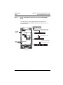
1
Instruction Bulletin
VVDED397045US
09/2002
Raleigh, NC, USA
ALTIVAR® 58 TRX
Adjustable Speed Drive
Controllers
FIPIO® Protocol Communication Card
User’s Guide
VW3A58301U
Retain for future use.
DANGER
HAZARDOUS VOLTAGE
• Read and understand this bulletin in its entirety before installing
or operating ALTIVAR 58 TRX drive controllers. Installation,
adjustment, repair, and maintenance of the drive controllers must
be performed by qualified personnel.
• The user is responsible for conforming to all applicable code
requirements with respect to grounding all equipment.
• Many parts in this drive controller, including printed wiring boards,
operate at line voltage. DO NOT TOUCH. Use only electrically
insulated tools.
• DO NOT short across DC bus capacitors or touch unshielded
components or terminal strip screw connections with voltage
present.
• Before servicing the drive controller:
— Disconnect all power including external control power that may
be present before servicing the drive controller.
— Place a “DO NOT TURN ON” label on the drive controller
disconnect.
— Lock the disconnect in open position.
— WAIT TEN MINUTES for the DC bus capacitors to discharge.
Then follow the DC bus voltage measurement procedure on
page 7 to verify that the DC voltage is less than 45 V. The drive
controller LEDs are not accurate indicators of the absence of
DC bus voltage.
• Install and close all covers before applying power or starting and
stopping the drive controller.
Electrical shock will result in death or serious injury.
VVDED397045US
09/2002
FIPIO® Protocol Communication Card User’s Guide
Table of Contents
TABLE OF CONTENTS
INTRODUCTION . . . . . . . . . . . . . . . . . . . . . . . . . . . . . . . . . . . . . . . . . . . . . . . . . . . . . 5
FIPIO Protocol Overview . . . . . . . . . . . . . . . . . . . . . . . . . . . . . . . . . . . . . . . . . . . . 6
REVISION LEVEL . . . . . . . . . . . . . . . . . . . . . . . . . . . . . . . . . . . . . . . . . . . . . . . . . . . . 6
ADDITIONAL DOCUMENTATION . . . . . . . . . . . . . . . . . . . . . . . . . . . . . . . . . . . . . . . . 6
RECEIVING, PRELIMINARY INSPECTION, AND STORAGE . . . . . . . . . . . . . . . . . . 7
BUS VOLTAGE MEASUREMENT PROCEDURE . . . . . . . . . . . . . . . . . . . . . . . . . . . . 7
INSTALLATION . . . . . . . . . . . . . . . . . . . . . . . . . . . . . . . . . . . . . . . . . . . . . . . . . . . . . 10
Card Installation . . . . . . . . . . . . . . . . . . . . . . . . . . . . . . . . . . . . . . . . . . . . . . . . . . 10
Setting a FIPIO Address for the ATV58 TRX Drive Controller . . . . . . . . . . . . . . . 11
CONNECTING TO THE FIPIO BUS . . . . . . . . . . . . . . . . . . . . . . . . . . . . . . . . . . . . . 12
Cable Routing Practices . . . . . . . . . . . . . . . . . . . . . . . . . . . . . . . . . . . . . . . . . . . . 14
FIPIO Card Display LEDs . . . . . . . . . . . . . . . . . . . . . . . . . . . . . . . . . . . . . . . . . . . 15
CONFIGURING COMMUNICATION FUNCTIONS . . . . . . . . . . . . . . . . . . . . . . . . . . 16
FIPIO Bus Start-Up Procedure . . . . . . . . . . . . . . . . . . . . . . . . . . . . . . . . . . . . . . . 16
SOFTWARE SETUP . . . . . . . . . . . . . . . . . . . . . . . . . . . . . . . . . . . . . . . . . . . . . . . . . 17
FIPIO CONFIGURATION USING PL7 PRO SOFTWARE . . . . . . . . . . . . . . . . . . . . . 17
About FIPIO Standard Profiles . . . . . . . . . . . . . . . . . . . . . . . . . . . . . . . . . . . . . . .
Data Exchange . . . . . . . . . . . . . . . . . . . . . . . . . . . . . . . . . . . . . . . . . . . . . . . . . . .
Implicit Data for ATV58 TRX Drive Controller . . . . . . . . . . . . . . . . . . . . . . . . .
Explicit Data for ATV58 TRX Drive Controller . . . . . . . . . . . . . . . . . . . . . . . . .
Effect and Use of the WRITE_PARAM function . . . . . . . . . . . . . . . . . . . .
Effect and Use of the READ_PARAM function . . . . . . . . . . . . . . . . . . . . .
Effect and Use of the SAVE_PARAM function . . . . . . . . . . . . . . . . . . . . .
Effect and Use of the RESTORE_PARAM function . . . . . . . . . . . . . . . . .
Diagnostic Objects . . . . . . . . . . . . . . . . . . . . . . . . . . . . . . . . . . . . . . . . . . . . .
17
18
20
23
24
24
24
25
25
PROGRAMMING THE PLC USING PL7 PRO SOFTWARE FOR THE ATV58 TRX
DRIVE CONTROLLER . . . . . . . . . . . . . . . . . . . . . . . . . . . . . . . . . . . . . . . . . . . . . . . . 26
Configuring the ATV58 TRX Drive Controller . . . . . . . . . . . . . . . . . . . . . . . . . . . . 29
CONTROL SCHEME OVERVIEW . . . . . . . . . . . . . . . . . . . . . . . . . . . . . . . . . . . . . . . 31
Forced Local . . . . . . . . . . . . . . . . . . . . . . . . . . . . . . . . . . . . . . . . . . . . . . . . . . . . .
Hand/Off/Auto (HOA) . . . . . . . . . . . . . . . . . . . . . . . . . . . . . . . . . . . . . . . . . . . . . .
Communication Fault Monitoring . . . . . . . . . . . . . . . . . . . . . . . . . . . . . . . . . .
Protection of Adjustment and Configuration Access . . . . . . . . . . . . . . . . . . . .
Access Protection by Forced Local . . . . . . . . . . . . . . . . . . . . . . . . . . . . . . . . .
© 2002 Schneider Electric All Rights Reserved
32
33
35
35
35
3
FIPIO® Protocol Communication Card User’s Guide
Table of Contents
4
VVDED397045US
09/2002
© 2002 Schneider Electric All Rights Reserved
FIPIO® Protocol Communication Card User’s Guide
Introduction
VVDED397045US
09/2002
INTRODUCTION
The FIPIO communication option card, VW3A58301U, allows the
connection of 1/2–100 hp ALTIVAR® 58 (ATV58) TRX drive
controllers to FIPIO networks. With the FIPIO communication card
installed, the ATV58 TRX drive controller can receive and respond to
data messages.
This data exchange enables a FIPIO network to access ATV58 TRX
drive controller functions such as:
•
•
Remote loading of configuration parameters
•
•
Monitoring of drive controller and motor status
Command and control registers for starting, stopping, and speed
control
Diagnostics and drive controller fault handling
WARNING
LOSS OF CONTROL
• The control scheme designer must consider the potential failure
modes of control paths.
• Certain critical control functions provide a means to achieve a
safe state during and after a path failure. 1
• Separate or redundant control paths must be provided for critical
control functions.
• System control paths may include communication links.
Consideration must be given to the implications of unanticipated
transmission delays or failures of the link. 2
Failure to follow this instruction can result in death, serious
injury, or equipment damage.
1
Examples of critical control functions are emergency stop and overtravel stop.
2
For additional information, refer to NEMA ICS 1.1 (latest edition), “Safety Guidelines for
the Application, Installation, and Maintenance of Solid State Control” and to NEMA
ICS7.1 (latest edition), “Safety Standards for Construction and Guide for Selection,
Installation and Operation of Adjustable-Speed Drive Systems.”
© 2002 Schneider Electric All Rights Reserved
5
FIPIO® Protocol Communication Card User’s Guide
Revision Level
VVDED397045US
09/2002
FIPIO Protocol Overview
The FIPIO fieldbus conforms to the FIP (Factory Instrumentation
Protocol) and WorldFIP standards. The standards define four
communication profiles for various levels of devices, with profile 1 for
simple devices and profile 4 for complex devices. FIPIO conforms to
profile 2 of the WorldFIP standard. The FIPIO network is a device bus
allowing for daisy-chaining, tap junctions, or a mix of both
configurations. It is the standard I/O bus for Schneider Electric's
Premium family of Programmable Logic Controllers (PLCs).
The data on the FIPIO network is transmitted at a binary rate of
1 Mbit/s across a shielded twisted-pair cable or fiber optic cable. Up
to 128 logical connections can be handled on one network. The
ATV58 TRX drive controllers support an address range of 1–62,
inclusive.
The FIPIO bus consists of a master device to perform the bus
arbitration and a number of other stations which produce and
consume the data messages. Messages are transferred on the FIPIO
bus to devices either cyclically, every PLC scan, or aperiodically,
using specific requests.
REVISION LEVEL
This is the first release of this manual. The information contained in it
is based on ATV58 firmware version V2.1 or greater.
ADDITIONAL DOCUMENTATION
For more information about drive controller functions and operation,
refer to the instruction bulletin supplied with your drive controller,
VVDED397048US, and the keypad display instruction bulletin,
VVDED397047US.
For register descriptions and address locations, refer to the ATV58
Register Access Guide for Communication Networks,
VVDED397058US.
6
© 2002 Schneider Electric All Rights Reserved
FIPIO® Protocol Communication Card User’s Guide
Receiving, Inspection, and Storage
VVDED397045US
09/2002
RECEIVING, PRELIMINARY INSPECTION, AND STORAGE
After receiving the VW3A58301U communication card:
•
Ensure that the catalog number printed on the box label is the
same as that on the packing slip and the corresponding purchase
order. Contact your local Square D representative if there are any
errors.
•
Observe the following precautions for handling static-sensitive
components while removing the card from its packaging for
inspection:
— Keep static-producing material (plastic, upholstery, carpeting,
etc.) out of the immediate work area.
— Avoid touching exposed conductors and component leads
with skin or clothing.
•
If any damage is found, notify the carrier and your local Square D
representative. Do not install a damaged card.
•
To store the option card, replace it in its original package
(including the anti-static bag) and store it at –40 to 185 °F (–40 to
85 °C).
BUS VOLTAGE MEASUREMENT PROCEDURE
Before installing the VW3A58301U communication card, measure the
bus voltage as described in this section.
DANGER
HAZARDOUS VOLTAGE
• Read and understand the bus voltage measurement procedure
before performing the procedure. Measurement of bus capacitor
voltage must be performed by qualified personnel.
• Many parts in this drive controller, including printed wiring boards,
operate at line voltage. DO NOT TOUCH. Use only electrically
insulated tools.
• Do not short across DC bus capacitors or touch unshielded
components or terminal strip screw connections with voltage
present.
Electrical shock will result in death or serious injury.
© 2002 Schneider Electric All Rights Reserved
7
FIPIO® Protocol Communication Card User’s Guide
Bus Voltage Measurement Procedure
VVDED397045US
09/2002
The DC bus voltage level is determined by monitoring the (+) and (–)
measurement points. Their location varies by drive controller model
number as listed in Table 1 and shown in Figure 1. The drive
controller model number is listed on the nameplate.
Table 1:
(+) and (–) Measurement Points
(+) Measurement Point
Drive Controller
ATV58•
Terminal
Block or
Connector
Terminal
Terminal
Block or
Designation
Connector
Terminal
Designation
(+)
J2
(–)
J2
PA
J18
7
J2
(+)
J2
(–)
U09M2• and U18M2• J2
U29M2• to D12M2•
U18N4• to D23N4•
D16M2• to D46M2•
D28N4• to D79N4•
(–) Measurement Point
To measure the DC bus capacitor voltage:
1. Disconnect all power from the drive controller including external
control power that may be present on the control board and the
option board terminals.
2. Wait ten minutes for the DC bus capacitors to discharge.
3. Read the model number of the drive controller from the nameplate
and identify the corresponding (+) and (–) measurement points
from Table 1 and Figure 1.
4. Open the door or cover of the drive controller.
5. Set the voltmeter to the 1000 Vdc scale. Measure the voltage
between the (+) and (–) measurement points identified in step 3.
Verify that the DC bus voltage has discharged below 45 V before
servicing the drive controller.
6. If the DC bus capacitors will not discharge below 45 V, contact
your local Square D representative. Do not operate the drive
controller.
7. Replace all doors or covers after servicing the drive controller.
8
© 2002 Schneider Electric All Rights Reserved
FIPIO® Protocol Communication Card User’s Guide
Bus Voltage Measurement Procedure
VVDED397045US
09/2002
Figure 1:
DC Bus Voltage Measurement Point Locations (ATV58HU09M2
shown)
The J18 connector is in the upper left hand corner of the main
control board behind the flexible shield. Use a thin probe to access
the connector pin.
J18-7
–
+
J18
Flexible
Shield
} ATV58•U29M2–D12M2
ATV58•U18N4–D23N4
L1 L2 L3 PA PB U
+
–
L1 L2 +
–
} ATV58•U09M2–U18M2
U
V W
+
–
Main Control
Board
L1 L2 L3 +
V W
} ATV58•D16M2–D46M2
ATV58•D28N4–D79N4
– PA PB U
V W
Power
Terminal
Block
© 2002 Schneider Electric All Rights Reserved
9
FIPIO® Protocol Communication Card User’s Guide
Installation
VVDED397045US
09/2002
INSTALLATION
Card Installation
To install the VW3A58301U communication card, consult Figure 2
and perform the following steps:
1. Verify that DC bus voltage is not present. See “Bus Voltage
Measurement Procedure” on page 7.
2. Place the 50/60 Hz switch in the position corresponding to the
motor as indicated in the drive controller user’s manual,
VVDED397048US.
3. Open the flexible protective cover ➀ over the option card
connector.
4. Mount the option card on the control card support by plugging it
into the connector ➁. Secure it with the three screws ➂ provided.
5. Connect the network cable to the 9-pin connector on the card ➃.
6. Replace all doors or covers when the installation is complete.
7. Affix the supplied self-adhesive label ➄ on the cover of the drive
controller, above the existing POWER and FAULT labels. This
aligns the label with the four LEDs on the communication card.
For information on LED indications refer to “FIPIO Card Display
LEDs” on page 15.
NOTE: Installing the card will reset drive controller programming to
factory defaults.
10
© 2002 Schneider Electric All Rights Reserved
FIPIO® Protocol Communication Card User’s Guide
Installation
VVDED397045US
09/2002
Figure 2:
Installing the Card in the Drive Controller
1
3
2
5
RUN
ERR
COM
I/O
1
POWER z
3
0
FAULT
6
Self-Adhesive Label
4
3
Setting a FIPIO Address for the ATV58 TRX Drive Controller
An ATV58 TRX drive controller on the FIPIO bus is identified by its
connection point. The number of the connection point represents the
physical address of the device on the FIPIO bus and may be a value
from 1 to 62.
For FIPIO, address 0 is reserved for the PLC that manages the bus.
Address 63 is also reserved.
Configure the FIPIO address of the drive controller using the address
switches ➅ on the card. Disconnect power to the drive controller
before setting the switches.
The address corresponds to the binary number given by setting
address switches 3 through 8 to 0 or 1. Switches 1 and 2 are not
used. The least significant bits are on the right. Two address
© 2002 Schneider Electric All Rights Reserved
11
FIPIO® Protocol Communication Card User’s Guide
Connecting to the FIPIO Bus
VVDED397045US
09/2002
examples are shown in Figure 3. If the switches are set to address 0,
FIPIO is deactivated.
Figure 3:
Switch Settings Examples
Binary Value: 32 16 8 4 2 1
Binary Value: 32 16 8 4 2 1
1
1
1
0
0
0
1
0
1 2 3 4 5 6 7 8
1 2 3 4 5 6 7 8
Address 1: 00000001
Address 5: 00000101
NOTE: Do not ever give two devices on the FIPIO bus the same
address. Continued simultaneous flashing of the standard LEDs
indicates that the device cannot connect to the FIPIO bus because its
address is already occupied by another device.
CONNECTING TO THE FIPIO BUS
Disconnect power to the ATV58 TRX drive controller before
connecting it to the FIPIO bus.
To connect an ATV58 TRX drive controller via the communication
card to a FIPIO network (as directed on page 10), use:
•
•
TSXFPACC12 connector (with ATV58H••••• and ATV58N•••••)
TSXFPACC2 connector (with ATV58E••••• and ATV58F•••••)
The following accessories are also available from Schneider
Automation for integrating ATV58 TRX drive controllers into the
FIPIO network:
•
TSXFPCA••• trunk cable sold in lengths of 100, 200, or 500 m
(328, 656, or 1640 ft)
•
•
•
•
TSXFPACC4 tap junction
TSXFPACC14 tap junction
TSXFPACC7 line terminator
TSXFPCG 010/030 from TSXFPP10 PCMCIA card miniature
connector to 9-pin SUB-D connector
For more information on connection to a FIPIO bus, consult the FIPIO
Bus/FIPWAY network reference manual, TSX DR FIP E. This manual
12
© 2002 Schneider Electric All Rights Reserved
FIPIO® Protocol Communication Card User’s Guide
Connecting to the FIPIO Bus
VVDED397045US
09/2002
contains all operating characteristics and start-up procedures for the
FIPIO fieldbus.
In addition, the Earth Connections Guide, TSX DG GND E, contains
useful installation rules and precautions for wiring a FIPIO fieldbus.
Figure 4:
Connecting the ATV58 TRX Drive Controller to the FIPIO Bus
TSXLES••
TSXFPACC7
ATV58 TRX controller
ATV58 TRX controller
TSXFPCA•••
TSXFPACC12
(with ATV58E•••••,
use TSXFPACC2)
TSXFPACC12
(with ATV58E•••••,
use TSXFPACC2)
TSXFPACC7
NOTE: Connection is also possible using a TSXFPACC4 or
TSXFPACC14 tap junction (see the Schneider Automation Premium
Automation Platform Catalog, number MKTED297001EN).
© 2002 Schneider Electric All Rights Reserved
13
FIPIO® Protocol Communication Card User’s Guide
Connecting to the FIPIO Bus
VVDED397045US
09/2002
Cable Routing Practices
When wiring the ATV58 TRX drive controllers to a FIPIO network,
follow all applicable wiring practices required by national and local
electrical codes.
When routing cable:
•
Avoid areas of high temperature, moisture, vibration, or other
mechanical stress.
•
Secure the cable where necessary to prevent its weight and the
weight of other cables from pulling or twisting the cable.
•
Use cable ducts, raceways, or other structures to protect the
cable. These structures should be used for signal wiring paths
and should not be used for power wiring.
•
Avoid sources of electrical interference that can induce noise into
the cable. Use the maximum practicable separation from such
sources.
When planning cable routing within a building, follow these
guidelines:
•
Maintain a minimum separation of 3.3 ft. (1 m) from the following
equipment:
— air conditioners and large blowers
— elevators and escalators
— radio and television sets
— intercom and security systems
— fluorescent, incandescent, and neon lighting fixtures
•
Maintain a minimum separation of 10 ft. (3 m) from the following
equipment:
— power wiring
— transformers
— generators
— alternators
14
© 2002 Schneider Electric All Rights Reserved
FIPIO® Protocol Communication Card User’s Guide
Connecting to the FIPIO Bus
VVDED397045US
09/2002
When wiring in electrical equipment rooms or large electrical
equipment line-ups, observe the following guidelines for cable
segregation and separation of circuits:
•
Use metallic conduit for drive controller wiring. Do not run control
network and power wiring in the same conduit.
•
Separate non-metallic conduits or cable trays used to carry power
wiring from the metallic conduit carrying low-level network wiring
by at least 12 in. (305 mm).
•
Separate metallic conduits carrying power wiring or low-level
control network wiring by at least 3 in. (80 mm).
•
Cross the metallic conduits and non-metallic conduits at right
angles whenever power and control network wiring cross.
•
Attenuate conducted emissions from the drive controller to the
line in some installations to prevent interference with
telecommunication, radio, and sensitive electronic equipment.
Such instances may require attenuating filters. Consult the AC
drives catalog, 8806CT9901, for selection and application of
these filters.
FIPIO Card Display LEDs
The card has four LEDs as shown in Figure 5.
Figure 5:
Location of LEDs and Address Switches
Green: RUN
Red: ERR
4 LEDs
Yellow: COM
Red: I/O
1
0
1
8
Address switches
Table 2 shows what the LED states indicate for each of the four
LEDs.
© 2002 Schneider Electric All Rights Reserved
15
FIPIO® Protocol Communication Card User’s Guide
Configuring Communication Functions
Table 2:
VVDED397045US
09/2002
LED State Indications
RUN LED
ERR LED
COM LED
I/O LED
What is indicated
On
Off
Rapid flash 1
Off
Normal operation
Flashes
Flashes
Flashes
Flashes
Auto-test at
initialization or
communication fault
On
Minor internal fault
Off
Not operating.
On
On
On
Off
Off
Off
1
Serious fault
Off
The COM LED flashes rapidly when there are communication exchanges on the bus and
is off when there are no exchanges.
NOTE: For more information on faults and fault codes, refer to the
instruction bulletin supplied with your drive controller.
CONFIGURING COMMUNICATION FUNCTIONS
FIPIO Bus Start-Up Procedure
It is recommended that you start-up the devices consecutively in the
order of the bus physical layout. For a detailed description of the
initial start-up of an application on FIPIO, refer to the FIPIO bus /
FIPWAY® network reference manual, TSX DR FIP E.
16
© 2002 Schneider Electric All Rights Reserved
FIPIO® Protocol Communication Card User’s Guide
Software Setup
VVDED397045US
09/2002
SOFTWARE SETUP
Figure 6 shows how to verify the protocol (FIPIO in this case) and the
communication address as read from the card switches by using the
drive controller's keypad display.
Figure 6:
8—Communication Menu
ENT
ENT
SL
-Pro
-Pro
Protocol
8.Communication
FIPIO
ESC
ESC
ENT
AdrC
1
Comm.Addr.
Comm.Addr.
ESC
(Example for address 1)
NOTE: For more information on drive controller configuration, refer to
the Keypad Display instruction bulletin, VVDED397047US.
FIPIO CONFIGURATION USING PL7 PRO SOFTWARE
The ATV58 TRX drive controller can be added to a FIPIO network
using PL7 Pro software, version 3.4 or higher. This section describes
in detail the steps required to set up the drive controller as a device
on the FIPIO network. For more information on how to use the
PL7 Pro software, see the User's guide TLX DR PL7 4xE (English
version).
About FIPIO Standard Profiles
The ATV58 TRX drive controller is declared as a connection point on
the FIPIO network by assigning to it the attributes of one of the
standard (STD_P) family profiles. These profiles are defined by the
number of I/O to be exchanged with the bus manager. The drive
controller uses the FIPIO Simple Device (FSD) profile having the
© 2002 Schneider Electric All Rights Reserved
17
FIPIO® Protocol Communication Card User’s Guide
FIPIO Configuration Using PL7 Pro Software
VVDED397045US
09/2002
structure FSD C8P. The profile defines the FIPIO bus connection
point parameters where:
•
•
•
C: indicates compact
8: is the number of cyclical I/O objects managed by the PLC
P: indicates additional parameters, namely 16 configuration words
and 32 adjustment words.
In PL7 Pro software, for ATV58 TRX drive controllers, this profile is
predefined and transparent to the user because the software allows
for selection of the drive controller by its part number.
Data Exchange
Data exchanges between the PLC and the drive controller over a
FIPIO network fall into two categories, implicit exchanges and explicit
exchanges. Implicit exchanges are done automatically by the PLC
and no additional programming is required to obtain and transfer
these implied data objects. Implicit data is also called cyclic or
periodic data because it is refreshed every PLC scan cycle. Explicit
data exchanges, on the other hand, require additional programming
in the PLC and the use of specific communication request codes to
obtain data, or to read and write specific variables.
Upon each logical reconnection of the ATV58 TRX drive controller to
the FIPIO bus, the PLC loads the drive controller with the following:
•
16 configuration objects (%KW\p.2.c\0.0.0 to %KW\p.2.c\0.0.15),
containing the data for 32 ATV58 configuration parameters
•
32 adjustment parameters (%MW\p.2.c\0.0.4 to
%MW\p.2.c\0.0.35)
This initialization occurs under the following conditions:
•
Every time the drive controller power is cycled when connected to
the FIPIO bus
•
On reconnection of the drive controller to the FIPIO bus after it
has been physically disconnected
•
On reconnection of the PLC (bus master) to the FIPIO bus
A summary of the data exchanged using the FSD C8P profile, along
with the object types used in PL7 programming, is given in Table 3.
18
© 2002 Schneider Electric All Rights Reserved
FIPIO® Protocol Communication Card User’s Guide
FIPIO Configuration Using PL7 Pro Software
VVDED397045US
09/2002
Table 3:
The FSD C8P Profile Data Exchanged
FSD C8P Registers
(PL7 objects) 1
Exchange
Type
Description
Read inputs
%IW\p.2.c\0.0.0
%IW\p.2.c\0.0.7
implicit
8 PLC input words from the controller
Control outputs
%QW\p.2.c\0.0.0
%QW\p.2.c\0.0.7
implicit
8 PLC output words to the controller
Configuration words
%KW\p.2.c\0.0.0
%KW\p.2.c\0.0.15
implicit
16 ATV58 TRX configuration words
from the PLC
Managing exchange
status
%MW\p.2.c\0.0.0
implicit
1 memory word for communication
exchange status
Exchange report
%MW\p.2.c\0.0.1
implicit
1 memory word for communication
exchange report
Standard channel status
%MW\p.2.c\0.0.2
explicit
1 memory word for additional status
information; 8 least-significant bits for
the controller and 8 most-significant
bits for the PLC
Validity of inputs
%MW\p.2.c\0.0.3
explicit
1 memory word used for input word
validation
Special channel status
—
—
—
Control words
—
—
—
Adjustment words
%MW\p.2.c\0.0.4
%MW\p.2.c\0.0.35
—
32 ATV58 TRX adjustment words,
accessed via explicit exchange
functions (see Table 9 on page 23)
Fault channel
%I\p.2.c\0.0.ERR
implicit
1 input bit indicating a FIPIO link fault
(when bit is set to 1)
1
Register Legend:
• p: 0 or 1 depending on the processor slot
• c: device connection point number (address)
© 2002 Schneider Electric All Rights Reserved
For example:
%MW\p.2.c\0.0.2 (standard channel status), where the
PLC processor is 0 and the device address is 54,
appears in PL7 Pro software as %MW\0.2.54\0.0.2
19
FIPIO® Protocol Communication Card User’s Guide
FIPIO Configuration Using PL7 Pro Software
VVDED397045US
09/2002
Implicit Data for ATV58 TRX Drive Controller
Tables 4 and 5 describe the ATV58 TRX drive controller words that
are exchanged with the PLC on a periodic basis, or every scan cycle
of the PLC. The PLC performs a cyclical refresh of all %IW registers
at the beginning of the drive controller program task. The %QW
registers are also refreshed at the end of the PLC’s program task.
Table 4:
Input Words to PLC from Drive Controller
Object Reference
Drive Controller Register
Code
Description
%IW\p.2.c\0.0.0
W458
ETA
ATV58 TRX controller status
%IW\p.2.c\0.0.1
W605
RFRD
Motor speed in rpm
%IW\p.2.c\0.0.2
W453
LCR
Motor current
%IW\p.2.c\0.0.3
W478
IOLR
Logic I/O status
%IW\p.2.c\0.0.4
W479
AI1R
Status of analog input 1
%IW\p.2.c\0.0.5
W487
OTR
Motor torque
%IW\p.2.c\0.0.6
W483
DF1
Fault code
%IW\p.2.c\0.0.7
W459
ETI
Internal status
Table 5:
Output Words from PLC to Drive Controller
Object Reference
Drive Controller Register
Code
Description
%QW\p.2.c\0.0.0
W400
CMD
Command register
%QW\p.2.c\0.0.1
W603
LFRD
Speed reference in rpm
%QW\p.2.c\0.0.2
W402
CMI
Internal control
%QW\p.2.c\0.0.3
W478
IOLR
Logic I/O status
%QW\p.2.c\0.0.4
W403
PISP
PI setpoint
%QW\p.2.c\0.0.5
—
—
reserved
%QW\p.2.c\0.0.6
—
—
reserved
%QW\p.2.c\0.0.7
—
—
reserved
The output of the ATV58 TRX drive controller responds to the values
sent by the PLC each time an application program execution cycle is
completed. However, if the values sent by the PLC are not received
for a period of at least 256 ms, the drive controller parameters are set
to their default values and the controller stops the motor on the
deceleration ramp.
Returning to normal communication automatically places the drive
controller under the control of the PLC once again, and if the network
run command is issued, the drive controller will start the motor.
20
© 2002 Schneider Electric All Rights Reserved
FIPIO® Protocol Communication Card User’s Guide
FIPIO Configuration Using PL7 Pro Software
VVDED397045US
09/2002
The %IW, %QW, and %KW words are explained in the ATV58
Register Access Guide for Communication Networks,
VVDED397058US.
There are also 32 drive controller configuration words that can be
managed by implicit exchange in the PLC via 16 programming object
references. The 16 word references are used in groups of bits or
whole words to indicate the value of the parameters. These values
are coded in hexadecimal format. Table 6 describes the drive
controller parameters used. See page 29 to set up the configuration
using PL7 Pro software.
Table 6:
Configuration Words
Drive
Controller
Register
Controller
Parameter
Codes
W11
W3
ORT
CFG
W101
W102
LI2
LI3
W103
W110
W107
LI4
R2
AI2
• logic input LI4
• relay R2
• analog input AI2
%KW\p.2.c\0.0.4
W4
W5
CRL
CRH
Min./Max. range setting of AI2
%KW\p.2.c\0.0.5
W7
W8
W9
TCT
PST
STR
• 2-wire control type
• Keypad STOP button priority
• Speed reference memory
%KW\p.2.c\0.0.6
W151
W155
W152
W154
OPL
FLR
IPL
LFL
•
•
•
•
Setting of output phase loss detection
Catch on the fly
Input phase loss
Response to loss of 4-20 mA follower signal
%KW\p.2.c\0.0.7
W153
W64
W63
W62
THT
BRA
DCF
RPT
•
•
•
•
Selection of motor thermal protection type
Deceleration ramp adaptation
Deceleration coefficient for fast stop
Type of acceleration and deceleration ramps
%KW\p.2.c\0.0.8
W69
W50
W51
PCC
SFT
SFR
• Motor power coefficient for motor switching
• Switching frequency type
• PWM switching frequency
%KW\p.2.c\0.0.9
W60
W8
W61
W70
NRD
STP
NLD
SPC
•
•
•
•
PL7 Object
Reference
Description
%KW\p.2.c\0.0.0
%KW\p.2.c\0.0.1
%KW\p.2.c\0.0.2
• Standard/High torque selection
• Macro Configuration—Handling, General
Use, Variable Torque
Assignment of logic inputs LI2 and LI3
Assignment of:
%KW\p.2.c\0.0.3
© 2002 Schneider Electric All Rights Reserved
Noise reduction feature
Controlled stop options
Energy saving feature
Selection of special motors
21
FIPIO® Protocol Communication Card User’s Guide
FIPIO Configuration Using PL7 Pro Software
Table 6:
VVDED397045US
09/2002
Configuration Words (continued)
PL7 Object
Reference
Drive
Controller
Register
Controller
Parameter
Codes
Description
%KW\p.2.c\0.0.10
W55
UNS 1
Motor nameplate voltage
%KW\p.2.c\0.0.11
W53
FRS 1
Motor nameplate frequency
%KW\p.2.c\0.0.12
W54
NCR 1
Motor nameplate current
%KW\p.2.c\0.0.13
W56
NSP
%KW\p.2.c\0.0.14
W57
COS 1
Motor nameplate power factor
%KW\p.2.c\0.0.15
W52
TFR 1
Maximum output frequency
%KW\p.2.c\0.0.16
W287
PIC 1
Inverts the PI feedback signal
1
1
Motor nameplate speed
These parameter values are determined based on the drive controller model number selected in PL7 Pro
software during configuration.
Table 7:
Network Status Words
Object Reference
Description
Bit Significance
X0=1: Reading of status word is in progress
X1=1: Send control parameters
%MW\p.2.c\0.0.0
Progress of network
exchange
X2=1: Send adjustment parameters
X3 to X14 are reserved
X15=1: Configuration in progress
X0=0: Reading of status word is OK (end of exchange)
X1=0: Control parameters are OK
%MW\p.2.c\0.0.1
X2=0: Adjustment parameters are OK
Status report
X3 to X14 are reserved
X15=0: Configuration accepted
For example:
Register Legend:
• p: 0 or 1 depending on the processor slot
• c: device connection point number (address)
Table 8:
%MW\p.2.c\0.0.1 (status report), where the PLC
processor is 0 and the device address is 54, appears in
PL7 Pro software as %MW\0.2.54\0.0.1
Network Status Bits
Object Reference
Description
Bit Significance
%I\p.2.c\0.0.ERR 1
Channel fault
bit=1: Interruption of FIPIO link between ATV58 TRX drive
controller and PLC
%I\p.2.c\0.MOD.ERR
Module fault
bit=1: Interruption of FIPIO link between ATV58 TRX drive
controller and PLC while in forced local mode
1
22
When the Channel Fault status bit = 1, the %IW objects cannot be used by the PLC program.
© 2002 Schneider Electric All Rights Reserved
FIPIO® Protocol Communication Card User’s Guide
FIPIO Configuration Using PL7 Pro Software
VVDED397045US
09/2002
Explicit Data for ATV58 TRX Drive Controller
Explicit objects are managed on request by the user's program using
the following PL7 Pro instructions for manipulating adjustment
parameters:
•
•
•
•
WRITE_PARAM%CH\p.2.c\0.0
READ_PARAM%CH\p.2.c\0.0
SAVE_PARAM%CH\p.2.c\0.0
RESTORE_PARAM%CH\p.2.c\0.0
The 32 adjustment parameters affected in the drive controller by the
above functions are listed in Table 9. These functions are intended to
be used only if the configuration is to be defined and controlled by the
PLC (local configuration box unchecked in PL7 Pro software).
Table 9:
Adjustment Parameters
Object Reference
Drive
Controller
Code
Object Reference
Drive
Controller
Code
%MW\p.2.c\0.0.4
HSP
%MW\p.2.c\0.0.20
TLS
%MW\p.2.c\0.0.5
LSP
%MW\p.2.c\0.0.21
RPG
%MW\p.2.c\0.0.6
ACC
%MW\p.2.c\0.0.22
RIG
%MW\p.2.c\0.0.7
DEC
%MW\p.2.c\0.0.23
FBS
%MW\p.2.c\0.0.8
ITH
%MW\p.2.c\0.0.24
JPF
%MW\p.2.c\0.0.9
reserved
%MW\p.2.c\0.0.25
TL2
%MW\p.2.c\0.0.10
reserved
%MW\p.2.c\0.0.26
FTD
%MW\p.2.c\0.0.11
AC2
%MW\p.2.c\0.0.27
CTD
%MW\p.2.c\0.0.12
DE2
%MW\p.2.c\0.0.28
TTD
%MW\p.2.c\0.0.13
IDC
%MW\p.2.c\0.0.29
BRL
%MW\p.2.c\0.0.14
TDC
%MW\p.2.c\0.0.30
IBR
%MW\p.2.c\0.0.15
FLG
%MW\p.2.c\0.0.31
BRT
%MW\p.2.c\0.0.16
STA
%MW\p.2.c\0.0.32
BEN
%MW\p.2.c\0.0.17
UFR
%MW\p.2.c\0.0.33
BET
%MW\p.2.c\0.0.18
PFL
%MW\p.2.c\0.0.34 1
FRT
%MW\p.2.c\0.0.19
SLP
%MW\p.2.c\0.0.35 1
CLI
1
%MW\p.2.c\0.0.34 and %MW\p.2.c\0.0.35 are configuration parameters that are only
taken into account by the drive controller when it is stopped or on initial power up.
© 2002 Schneider Electric All Rights Reserved
23
FIPIO® Protocol Communication Card User’s Guide
FIPIO Configuration Using PL7 Pro Software
VVDED397045US
09/2002
Effect and Use of the WRITE_PARAM function
To change the initial configuration, use the Animation Table tool in
PL7 Pro software to modify adjustment parameters. When the PLC
next performs the WRITE_PARAM function these parameters are
saved in the drive controller.
For example, to modify an adjustment parameter online:
•
Change the value of the adjustment parameter object,
%MW\p.2.c\0.0.4, to 0.0.35, using an Animation Table
•
•
Initiate the execution of the function WRITE_PARAM
Verify the modification at the drive controller using the keypad
display or PC software
NOTE: It is not necessary to perform another Save command (i.e.,
set bit 1 of W402, CMI, or %QW\p.2.c\0.0.2 to 1). The modification is
automatically saved in EEPROM.
Effect and Use of the READ_PARAM function
The READ_PARAM instruction allows the PLC to read adjustment
parameters from the drive controller and update its status memory
dedicated to the adjustment parameters of the built-in drive controller
interface task.
For example, to read a parameter changed locally at the drive
controller via its keypad display or PC software:
•
•
Initiate the execution of the READ_PARAM function
Check for the updated value using an Animation Table
NOTE: This value will not be stored in the PLC unless the
SAVE_PARAM function is given prior to removal of power or
disconnection of the network.
Effect and Use of the SAVE_PARAM function
The SAVE_PARAM instruction is used to save drive controller
parameters in the PLC processor. This operation is local, at the PLC
level, and does not change parameters in the drive controller. Use
SAVE_PARAM to update and replace the PLCs existing adjustment
parameters as well as those used for the next initialization.
24
© 2002 Schneider Electric All Rights Reserved
FIPIO® Protocol Communication Card User’s Guide
FIPIO Configuration Using PL7 Pro Software
VVDED397045US
09/2002
Effect and Use of the RESTORE_PARAM function
Using the RESTORE_PARAM instruction allows for restoration of the
initial adjustment parameters to the drive controller after an unsaved
change to the parameters. The values are those normally written
during initialization of configuration or those that existed in the PLC
during the last save function.
Diagnostic Objects
There are two diagnostic instructions available by explicit exchange
in PL7 Pro software.
The instruction READ_STS%CH\p.2.c\0.0 returns diagnostic
information on the drive controller status and
READ_STS%CH\p.2.c\0.MOD gets diagnostic information on the
network status. Table 10 describes the information the PLC software
receives from each of these software instructions.
Table 10:
PLC Software Response to Diagnostic Parameters
Object Type
Description
Bit Significance
PLC Instruction READ_STS%CH\p.2.c\0.0
X0=1: reserved
X1=1: Drive controller fault
X2=1: Forced Local mode
X3=1: Power supply fault
%MW\p.2.c\0.0.2
Standard channel
X4=1: reserved
X5=1: Hardware configuration fault; incompatible modules
X6=1: Communication fault with PLC
X7=1: reserved
X8–X15 reserved to 0
%MW\p.2.c\0.0.3
Validity of inputs
© 2002 Schneider Electric All Rights Reserved
X0–X7 not =0: Inputs to PLC are not valid; contain old data
25
FIPIO® Protocol Communication Card User’s Guide
Programming the PLC Using PL7 Pro Software
Table 10:
VVDED397045US
09/2002
PLC Software Response to Diagnostic Parameters
Object Type
Description
Bit Significance
PLC Instruction READ_STS%CH\p.2.c\0.MOD
X0=1: Internal fault
X1=1: Communication fault between bus manager and agent
X2=1: Not used
X3=1: Not used
%MW\p.2.c\0.MOD.2
Device status
X4=1: Not used
X5=1: Hardware or software configuration fault; the module
present is not the module declared in the configuration
X6=1: Module missing
X7=1: reserved
X8–X15 reserved to 0
PROGRAMMING THE PLC USING PL7 PRO SOFTWARE FOR THE ATV58 TRX
DRIVE CONTROLLER
Follow the instructions below to add an ATV58 TRX drive controller to
a FIPIO network using PL7 Pro software.
1. On your PC, start the PL7 Pro application.
2. Open an existing program or start a new one.
3. If starting a new program, choose the PLC’s processor type.
4. From the Application Browser in the Structure View window,
double-click the Configuration folder, double-click Hardware
Configuration.
26
© 2002 Schneider Electric All Rights Reserved
FIPIO® Protocol Communication Card User’s Guide
Programming the PLC Using PL7 Pro Software
VVDED397045US
09/2002
5. Double-click on the FIPIO box on the processor graphic to see the
network configuration.
Figure 7:
Hardware Configuration
FIPIO box
© 2002 Schneider Electric All Rights Reserved
27
FIPIO® Protocol Communication Card User’s Guide
Programming the PLC Using PL7 Pro Software
Table 11:
VVDED397045US
09/2002
FIPIO Configuration Dialog Box
used logical
address
node
unused
logical
address
node
6. Double-click on an unused logical address node. The Add/Modify
a Device dialog box opens.
Figure 8:
Sample Added/Modified Device
7. Choose ATV58 in the Families window.
8. Select your drive controller's part number in the Base Module
window.
9. Enter a connection point number (device address) and add a
description in the Comment box, if desired.
10. Click OK.
28
© 2002 Schneider Electric All Rights Reserved
FIPIO® Protocol Communication Card User’s Guide
Programming the PLC Using PL7 Pro Software
VVDED397045US
09/2002
Configuring the ATV58 TRX Drive Controller
From the FIPIO Configuration dialog box in PL7 Pro software, open
the ATV58 module by double-clicking on it. The drive controller
configuration/adjustment window opens. See Figures 9 and 10.
Figure 9:
Drive Controller Configuration
Local configuration box
You can assign a name in the Symbol column and define the symbol
names in PL7 Pro software using the %KW\p.2.c\0.0.0–0.0.15 object
types under Variables>I/O in the Application Browser. In the
Variables window make sure to select the drive controller from the
drop-down menu. For assignment instructions, use the PL7 Pro online help.
If you choose not to have the PLC manage these drive controller
configuration parameters, check the Local configuration box (see
Figure 9). Selecting the Local configuration hides the Configuration
parameter list in PL7 Pro software, indicating that these parameters
will not be managed by the PLC. This requires that the drive controller
be manually configured using the keypad display or PowerSuite PC
software.
The drive controller's adjustment parameters are also available from
this window through the drop-down menu in the upper left-hand
© 2002 Schneider Electric All Rights Reserved
29
FIPIO® Protocol Communication Card User’s Guide
Programming the PLC Using PL7 Pro Software
VVDED397045US
09/2002
corner (see Figure 10). 32 drive controller adjustment registers can
be specified for handling by the PLC. These registers are defined in
PL7 Pro software as %MW\p.2.c\0.0.4 to 0.0.35 data types. Define
the desired adjustment parameters under Variables>I/O in the
Application Browser. In the Variables window make sure to select the
drive controller from the drop-down menu.
Figure 10:
Drive Controller Adjustment
Select Adjust here
For parameter information, refer to the ATV58 Register Access Guide
for Communication Networks, VVDED397058US, or use the on-line
help to explain parameters in PL7 Pro software.
30
© 2002 Schneider Electric All Rights Reserved
FIPIO® Protocol Communication Card User’s Guide
Control Modes
VVDED397045US
09/2002
CONTROL SCHEME OVERVIEW
The ATV58 TRX drive controller can be controlled as follows:
•
through hard-wired I/O points on the control terminal strip (local
control mode)
•
through a keypad display module or computer with ATV58 PC
software connected to the drive controller’s built-in RS-485
MODBUS serial port (local control mode)
•
through a PLC or other controller connected to the fast serial link
via a communication card (serial link mode)
NOTE: The operator keypad display takes priority over the terminals.
In serial link mode the speed reference and the start/stop control
cannot come from separate sources. That is, it is not possible to have
the speed reference sent across the serial link and the start/stop
control from the terminal strip.
For details on how to select between the two modes of local (hand)
control see the latest revision of the keypad display manual,
VVDED397047US.
When the communication network has control of the drive controller,
the setpoints and commands are controlled via the network and
cannot be modified by the terminals, the keypad display, or any
device connected to the RS-485 MODBUS serial port. To command
the drive controller by the terminals or the keypad display, forced
local must be enabled.
WARNING
UNINTENDED EQUIPMENT ACTION
When in serial link mode, all terminal inputs are ignored except
digital inputs configured as stop functions and the Forced Local
input.
Failure to consider the implications of unanticipated
operations can result in death, serious injury, or equipment
damage.
© 2002 Schneider Electric All Rights Reserved
31
FIPIO® Protocol Communication Card User’s Guide
Control Modes
VVDED397045US
09/2002
Forced Local
Switching between local control mode and serial link mode is
achieved by a switch wired to a logic input on the controller terminal
block as illustrated in Figures 11 and 12 on page 34. The logic input
must be assigned to the function forced local.
When the logic input assigned to forced local is active (high), all
control of the drive controller is assigned to the selected local (hand)
control mode, and command requests by the network are refused.
Command parameters can be monitored. All other parameters can be
read accessed.
WARNING
UNINTENDED EQUIPMENT ACTION
When in forced local mode, all commands from the communication
ports are ignored.
Failure to consider the implications of unanticipated operation
can result in death, serious injury, or equipment damage.
When the forced local logic input is not active (low), all control of the
drive controller is transferred to the network if the controller is wired
as shown in Figures 11 or 12. The only local (hand) controls that are
still monitored by the drive controller are the logic input assigned to
forced local and any input assigned to a drive stop function.
Examples include:
•
•
the stop button on the keypad display module
•
any logic input assigned to the functions freewheel stop, DC
injection braking, and fast stop.
logic input one (LI1) which is assigned to the function STOP if the
drive controller is configured for 3-wire control
See the keypad display manual, VVDED397047US (latest revision),
for more details.
32
© 2002 Schneider Electric All Rights Reserved
FIPIO® Protocol Communication Card User’s Guide
Control Modes
VVDED397045US
09/2002
Hand/Off/Auto (HOA)
WARNING
LOSS OF CONTROL
The user must provide a Hand/Off/Auto switch with the following
functionality:
• In the Hand position, forced local mode must be enabled.
• In the Off position, all run terminal inputs must be disabled via
open circuit, and forced local mode must be enabled.
• In the Auto position, the run terminal inputs must be disabled via
open circuit, and forced local mode must be disabled.
Failure to follow this instruction can result in death or serious
injury.
When the control switch is in the auto position, all local run and start
commands to the drive controller must be removed. During powerup, the drive controller defaults to local control mode. (See “Control
Scheme Overview” on page 31.) After the drive controller recovers
from a power up sequence (including such unplanned events as an
AC line power disturbance), it immediately responds to any local
controls that are active before the FIPIO communication board has
initialized and assumed control. This can result in unintended
equipment operation.
When the control switch is in the hand or off position, the drive
controller must be placed into the forced local mode. While it is
possible to stop the drive controller in the serial link mode by
activating one of the local stop commands (such as the keypad
display stop button), commands sent over the network can restart the
drive controller if it is not in forced local mode. See “Forced Local” on
page 32.
Refer to Figures 11 and 12 on page 34 for assistance in designing
Hand/Off/Auto control. For the run reverse and forced local functions,
select any unused logic inputs on the main control board. Assign a
© 2002 Schneider Electric All Rights Reserved
33
FIPIO® Protocol Communication Card User’s Guide
Control Modes
VVDED397045US
09/2002
logic input to the run reverse function only if appropriate for the
application.
Figure 11:
Example 2-Wire Control
+24
Hand
Off
Auto
LI1 Run Forward
User
Control
Scheme
LIx Run Reverse
LIy Forced Local
The cross hatch ×
under the selector
switch position
indicates a closed
contact.
The user control
scheme determines
when the input is
activated.
NOTE: When the HOA switch is in the auto position, removing the
local run forward or run reverse commands does not stop the drive
controller.
Figure 12:
Example 3-Wire Control
+24
Stop
Hand
Off Auto
LI1 Stop
Fwd
LI2 Run Forward
Rev
The cross hatch ×
under the selector
switch position
indicates a closed
contact.
LIx Run Reverse
LIy Forced Local
NOTE: When the HOA switch is in the auto position, removing the
local run forward or run reverse commands does not stop the drive
controller.
34
© 2002 Schneider Electric All Rights Reserved
FIPIO® Protocol Communication Card User’s Guide
Control Modes
VVDED397045US
09/2002
Communication Fault Monitoring
Word 402, bit 14 of command register CMI is used to inhibit
communication fault responses. If bit 14 = 1, the drive controller
ignores communication errors from the serial link. This function is
intended for use during troubleshooting and start-up. Do not use this
function during normal network operation.
WARNING
UNINTENDED EQUIPMENT ACTION
Loss of communication will not cause the drive controller to fault
when bit 14 of Word 402 is set to 1.
Failure to consider implications of unanticipated operations
can result in death, serious injury, or equipment damage.
Protection of Adjustment and Configuration Access
A configuration semaphore has not been provided in order to ensure
read-only access to the configuration and adjustment parameters.
Any processing unit can access the configuration and adjustment
parameters.
Access Protection by Forced Local
Writing of Command registers is blocked when the controller is in
forced local mode.
© 2002 Schneider Electric All Rights Reserved
35
FIPIO® Protocol Communication Card User’s Guide
Control Modes
36
VVDED397045US
09/2002
© 2002 Schneider Electric All Rights Reserved
FIPIO® Protocol Communication Card User’s Guide
Index
VVDED397045US
09/2002
INDEX
P
Symbols
%I registers 19, 22
%IW registers 19–21
%KW registers 18, 19, 21, 29
%MW registers 18, 19, 22–
26, 30
%QW registers 19–21
A
PLC 31
R
receiving 7
S
serial link mode 31
storage 7
animation table 24
C
cable
protection 14
cable routing 14–15
control
local and serial link 31–32
modes 31–35
control sources 31
E
electrical interference 14
F
fast serial link 31
forced local 33
FSD C8P 18–19
H
Hand/Off/Auto 33
handling 7
I
inspection 7
L
local and serial link control 31–
32
local control mode 31
© 2002 Schneider Electric All Rights Reserved
37
91598275011101
W915982750111A01
FIPIO® Protocol Communication Card User’s Guide
Instruction Bulletin
Square D Company
8001 Highway 64 East
Knightdale, NC 27545 USA
1-888-SquareD (1-888-778-2733)
www.SquareD.com
Electrical equipment should be installed, operated, serviced, and
maintained only by qualified personnel. No responsibility is assumed
by Schneider Electric for any consequences arising out of the use of
this material.
VVDED397045US 09/2002
© 2002 Schneider Electric All Rights Reserved