1
Document No: 1015454
Revision: C
WatchMaster IP Elite Series
®
Fixed Mount, Fixed Focus Thermal IP and Analog Camera
User Manual
©Copyright 2012-2013, DRS TECHNOLOGIES, Inc. - All rights reserved.
13532 N. Central Expressway
Dallas, TX 75243
877.377.4783
www.drsinfrared.com
The contents of this document may not be reproduced in whole or in part without the
written consent of the copyright owner.
Rev History
Revision Number
Release Date
Description
A
3/13/2013
Initial Release
B
10/15/2013
Update
Images
C
11/20/2013
Correction to wiring section
and minor edits
descriptions
and
®
WatchMaster IP Elite User Manual
NOTICE
ALL STATEMENTS, INFORMATION, AND RECOMMENDATIONS IN THIS MANUAL
ARE BELIEVED TO BE ACCURATE BUT ARE PRESENTED WITHOUT WARRANTY
OF ANY KIND. NOTWITHSTANDING ANY OTHER WARRANTY HEREIN, ALL
DOCUMENT FILES AND SOFTWARE ARE PROVIDED “AS IS” WITH ALL FAULTS.
DRS DISCLAIMS ALL WARRANTIES, EXPRESSED OR IMPLIED, INCLUDING,
WITHOUT LIMITATION, THOSE OF MERCHANTABILITY, FITNESS FOR A
PARTICULAR PURPOSE AND NONINFRINGEMENT OR ARISING FROM A COURSE
OF DEALING, USAGE, OR TRADE PRACTICE.
IN NO EVENT SHALL DRS BE LIABLE FOR ANY INDIRECT, SPECIAL,
CONSEQUENTIAL, OR INCIDENTAL DAMAGES, INCLUDING, WITHOUT LIMITATION,
LOST PROFITS OR LOSS OR DAMAGE TO DATA ARISING OUT OF THE USE OR
INABILITY TO USE THIS MANUAL, EVEN IF DRS HAS BEEN ADVISED OF THE
POSSIBILITY OF SUCH DAMAGES.
THE SOFTWARE LICENSE AND LIMITED WARRANTY FOR THE ACCOMPANYING
PRODUCT ARE SET FORTH IN THE INFORMATION PACKET THAT SHIPPED WITH
THE PRODUCT AND ARE LOCATED HEREIN ON PAGE ii
i
®
WatchMaster IP Elite User Manual
DRS RSTA, INC.
END USER LICENSE AGREEMENT
FOR
®
WATCHMASTER FAMILY OF PRODUCTS SOFTWARE
®
THIS LICENSE AGREEMENT IS PROOF OF YOUR RIGHT TO USE THE WATCHMASTER SOFTWARE CONTAINED IN THE
®
DRS WATCHMASTER FAMILY OF PRODUCTS (THE “PRODUCTS”) AND PROVIDES ADDITIONAL INFORMATION
CONCERNING DRS' LIMITED WARRANTY AND LIMITATIONS OF LIABILITY. PLEASE READ IT CAREFULLY. BY ACCEPTING
OR USING THE PRODUCTS, YOU ARE AGREEING TO BE BOUND BY THE TERMS AND CONDITIONS OF THIS LICENSE
AGREEMENT.
This License Agreement (hereinafter the "Agreement") is between you (either an individual or an entity) and
DRS RSTA, Inc. and/or its affiliates ("DRS"). DRS is willing to grant you the following rights to use the
®
WATCHMASTER SOFTWARE incorporated in or supplied with the Products (collectively, the "DRS Software")
only if you agree to be bound by all of the terms and conditions of this Agreement. By accepting or using the
Products, you agree to be bound by all the terms and conditions of this Agreement. If you do not agree to be
bound by all of the terms and conditions of this Agreement, DRS is unwilling to grant you any rights to use the
DRS Software; instead you must promptly return the Products to DRS for a full refund or to the authorized
reseller that provided you with the Products.
1. OWNERSHIP: The DRS Software is and shall remain a proprietary product of DRS or its licensors and you hereby acknowledge
and agree that the DRS Software embodies valuable trade secrets proprietary to DRS and/or its licensors. All patents, copyrights,
trademarks, trade names, trade secrets and other proprietary rights relating to or residing in the DRS Software shall be owned or
licensed exclusively by DRS. Except for the license provided in Section 2, you shall have no right, title or interest in or to the DRS
Software. The DRS Software is licensed, not sold, to you for use only under the terms and conditions of this Agreement. Furthermore,
you agree to be bound by the terms and conditions of this Agreement with respect to any and all upgrades or updates to the DRS
Software provided to you by DRS or the authorized reseller that provided you with the Products.
2. GRANT OF LICENSE: Subject to your full compliance with all terms and conditions set forth in this Agreement, DRS grants you a
nontransferable (except as specifically set forth in this Section) non-exclusive, restricted right to use the DRS Software as incorporated
in or supplied with the Products and solely in connection with the use of the Products. You may make a reasonable number of back-up
copies of the DRS Software. You understand that DRS may update the DRS Software at any time and in doing so incurs no obligation
to furnish such updates to you pursuant to this Agreement. You may transfer the license to use the DRS Software only in connection
with a sale or transfer of the Products and only as included with the Products and not on a stand-alone basis, provided the buyer or
transferee agrees in writing to be bound by all the terms and conditions of this Agreement.
3. RESTRICTIONS/LIMITATIONS: Except as expressly authorized in Section 2, you may not use, copy, modify, create derivative
works of, distribute, sell, assign, pledge, sublicense, lease, loan, rent, timeshare, or disclose the DRS Software, in whole or in part, at
any time for any reason, nor permit any other party to do any of the foregoing. You specifically agree that you will not provide access
to the DRS Software to any person or party other than for the intended use of the DRS Software as authorized hereunder. You may
not remove from the DRS Software, or alter, any of the trademarks, trade names, logos, patent or copyright notices or markings, or
add any other notices or markings to the DRS Software. You may not install or use the DRS Software on any product other than the
Products. You specifically agree not to reverse engineer, decompile, disassemble, or reverse translate the DRS Software or any part
thereof. The license granted in Section 2 shall immediately terminate if you use the DRS Software in a manner that exceeds the scope
of the license granted hereunder and/or upon any breach of the terms and conditions of this Agreement.
4. LIMITED WARRANTY: DRS does not warrant that the functions contained in the DRS Software will meet your requirements or that
the DRS Software will be uninterrupted or error-free. DRS warrants that for a period of twenty-four (24) months from the original
shipment date that the DRS Software will perform substantially as described in the applicable Software User Manual during normal
use. This limited warranty is void if failure of the DRS Software to conform to the warranty has resulted from improper installation,
testing, misuse, neglect, accident, fire or other hazard, or any breach of this Agreement.
5. LIMITED REMEDIES: In the event of a breach of the foregoing limited warranty, DRS will, at its own expense, use commercially
reasonable efforts to promptly and diligently correct all issues with the DRS Software (except those classified as Class 3 issues, which
means cosmetic and minor anomalies; functionality is impaired). DRS's sole and exclusive obligation and your sole and exclusive
remedy shall be, at DRS's sole discretion, to repair or replace the nonconforming DRS Software.
6. NO OTHER WARRANTIES: OTHER THAN THE FOREGOING LIMITED WARRANTY, DRS HEREBY EXPRESSLY DISCLAIMS
ALL OTHER WARRANTIES, EXPRESS OR IMPLIED, INCLUDING WITHOUT LIMITATION THE IMPLIED WARRANTIES OF
MERCHANTABILITY AND FITNESS FOR A PARTICULAR PURPOSE. SOME JURISDICTIONS DO NOT ALLOW THE DISCLAIMER
OF IMPLIED WARRANTIES, SO THE ABOVE DISCLAIMER MAY NOT APPLY TO YOU, IN WHICH CASE THE DURATION OF ANY
SUCH IMPLIED WARRANTIES IS LIMITED TO SIXTY (60) DAYS FROM THE DATE THE PRODUCTS IS RECEIVED BY YOU.
7. INTELLECTUAL PROPERTY: Up to the aggregate limit specified in Section 8 below, DRS shall indemnify, defend and hold you
harmless against and pay all costs and damages awarded against you resulting from a claim that the DRS Software infringes any U.S.
patent or copyright or misappropriates a U.S. trade secret, provided that you (a) provide DRS with written notice of such claim within
thirty (30) days of being notified of the claim; (b) allow DRS to exclusively control the defense and/or settlement of such claim; and (c)
provide any information, authority and assistance that DRS reasonably deems necessary for the defense and/or settlement of any
such claim, provided that any reasonable costs and expenses incurred by you in providing such information and assistance will be
reimbursed by DRS. You agree not to consent to any judgment or decree or do any other act in compromise of any such claim without
first obtaining DRS's written consent. In any action based on such a claim, DRS may, in its sole discretion and at its own expense,
either: (1) procure for you the license right to continue using the DRS Software; or (2) replace or modify the DRS Software to avoid the
claim. If neither of the foregoing is reasonably practicable, DRS may terminate the license and refund the license amount paid. DRS
will not be liable for any costs or expenses incurred by you in connection with any claims subject to the terms of this Section without
the prior written authorization by DRS. Notwithstanding the provisions of this Section, DRS assumes no liability or obligation to
indemnify for any infringement or misappropriation claim of any kind arising from: (a) use or combination of the DRS Software with
other software or products not provided by DRS, if such infringement claims would not have arisen with respect to the DRS Software
standing alone, or (b) any modifications, enhancements or revisions to the DRS Software unless made or approved in writing by DRS.
The foregoing provisions state the entire liability and obligations of DRS and the sole and your exclusive remedy with respect to any
actual or alleged infringement or misappropriation of any intellectual property rights regarding or involving the DRS Software.
ii
®
WatchMaster IP Elite User Manual
8. LIMITATION OF LIABILITY: THE AGGREGATE LIABILITY OF DRS OR ITS SUPPLIERS IN CONNECTION WITH THIS
AGREEMENT AND THE DRS SOFTWARE, REGARDLESS OF THE FORM OF THE ACTION GIVING RISE TO SUCH LIABILITY
(WHETHER IN CONTRACT, TORT OR OTHERWISE), SHALL NOT EXCEED THE AMOUNT PAID BY YOU TO DRS OR
RESELLER FOR THE PRODUCTS, OR USD $100,000.00, WHICHEVER IS LESS. NEITHER DRS NOR ITS SUPPLIERS SHALL BE
LIABLE TO YOU FOR ANY INDIRECT, EXEMPLARY, SPECIAL (INCLUDING PUNITIVE OR MULTIPLE), CONSEQUENTIAL OR
INCIDENTAL DAMAGES OF ANY KIND (INCLUDING WITHOUT LIMITATION LOSS OF DATA, EQUIPMENT DOWNTIME OR LOST
PROFITS), EVEN IF DRS OR ITS SUPPLIERS HAVE BEEN ADVISED OF THE POSSIBILITY OF SUCH DAMAGES. THE LIMITED
WARRANTY, LIMITED REMEDIES AND LIMITED LIABILITY PROVISIONS CONTAINED IN THIS AGREEMENT ARE
FUNDAMENTAL PARTS OF THE BASIS OF DRS’ BARGAIN HEREUNDER, AND DRS WOULD NOT PROVIDE THE DRS
SOFTWARE TO YOU ABSENT SUCH LIMITATIONS.
®
9. U.S. GOVERNMENT END USERS: This provision only applies to u.s. Government end users. The WATCHMASTER
SOFTWARE and any provided documentation are commercial items as that term is defined at 48 C.F.R. Part 2.101, consisting of
"commercial computer software" and "computer software documentation" as such terms are defined in 48 C.F.R. Part 252.2277014(a)(1) and 48 C.F.R. Part 252.227-7014(a)(5), and used in 48 C.F.R. Part 12.212 and 48 C.F.R. Part 227.7202, as applicable.
Consistent with 48 C.F.R. Part 12.212, 48 C.F.R. Part 252.227-7015, 48 C.F.R. Part 227.7202-1 through 227.7202-4, 48 C.F.R. Part
52.227-19, and other relevant sections of the Code of Federal Regulations, as applicable, and as may be amended or updated from
®
time-to-time, the WATCHMASTER SOFTWARE and any provided documentation are distributed and licensed to U.S. Government
end users (a) only as commercial items, and (b) with only those rights as are granted to all other end users pursuant to the terms and
®
conditions contained herein. The WATCHMASTER SOFTWARE is provided with Restricted Rights, as such term is defined in 48
C.F.R. Part 252.227-7014(a)(14).
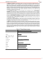
10. THIRD PARTY SOFTWARE LICENSES: The DRS Software may contain third party software, which requires the application of
third party terms and conditions (reference Table 1 below). Such third party terms and conditions are located in .txt files or other
documentation of each third party software component. By accepting this Agreement, you also agree to accept and be bound by any
such applicable third party additional terms and conditions, if any, as referenced herein.
11. GENERAL: This Agreement shall be governed by and interpreted in accordance with the laws of the state of New York, U.S.A.,
excluding its conflict of laws principles. The United Nations Convention on Contracts for the International Sale of Goods is specifically
disclaimed. If any provision of this Agreement is held by a court of competent jurisdiction in the United States to be unenforceable for
any reason, the remaining provisions hereof shall be unaffected and remain in full force and effect as if this Agreement had been
executed with the invalid portion eliminated, provided the effectiveness of the remaining portions of this Agreement will not defeat the
overall intent of the parties. In such a situation, the parties agree, to the extent legal and possible, to incorporate a replacement
provision to accomplish the originally intended effect. This Agreement is the final, complete and exclusive agreement between the
parties relating to the subject matter hereof, and supersedes all prior or contemporaneous understandings and agreements relating to
such subject matter, whether oral or written, and may only be modified by a written instrument executed by an authorized
representative of each party.
Table i: 3rd Party Software License
GSOAP
http://www.genivia.com/Products/gsoap/contract.h® l
H.264 encoder
http://www.mpegla.com/main/programs/AVC/Pages/AgreementExpress.asp
x
ONVIF™
www.onvif.org
H.264 decoder (Video LAN
SW)
(VLC
provides
SourceFreeware)
http://www.gnu.org/licenses/gpl.h® l
Live 555 server
http://www.live555.com/liveMedia/#license
Linux kernel
http://www.kernel.org
Lighttpd
http://www.lighttpd.net/
dhcpcd
http://www.phystech.com/download/dhcpcd.h® l
ntpclient
http://doolittle.icarus.com/ntpclient/
zeroconfig
http://avahi.org/wiki/AboutAvahi
esmtp
http://sourceforge.net/projects/esmtp/
iii
®
WatchMaster IP Elite User Manual
REGULATORY AND SAFETY
FCC
This equipment has been tested and found to comply with the limits of FCC Class A Part
15 Subpart B. This equipment also complies with Canadian CES-003.
CE
This equipment complies with CE standard as below.
For Europe (CE):
IEC 60065:2001 + Amd 1:2005 / EN 60065:2002
UL
This equipment is approved by UL and is compliant to below specifications.
For North America (UL):
UL 60065, 7th Edition, 2007-12-11
CAN/CSA-C22.2 No. 60065-03, 1st Edition, 2006-04 + A1:2006
RoHS
This equipment complies with the European ROHS directive, 2011-65-EC.
WEEE
This equipment must be disposed of as electronic waste. Contact your nearest DRS
Representative for instructions on how to return the product for proper disposal.
iv
®
WatchMaster IP Elite User Manual
TABLE OF CONTENTS
1
Introduction ................................................................................................................. 1
1.1
2
Product Overview ........................................................................................................ 2
2.1
2.2
3
Live Video .................................................................................................................. 41
Motion Detection ........................................................................................................ 43
Video Storage ............................................................................................................ 45
Maintenance ............................................................................................................. 48
7.1
7.2
7.3
7.4
7.5
7.6
7.7
7.8
8
9
DRS Web Interface and Access Privilege ................................................................... 24
Setup.......................................................................................................................... 25
Use and Application .................................................................................................. 41
6.1
6.2
6.3
7
Package Contents ...................................................................................................... 10
Installation .................................................................................................................. 11
Installation Procedure ................................................................................................. 12
Preparing the Cable ................................................................................................... 13
Assembly.................................................................................................................... 17
Mounting the Camera ................................................................................................. 20
Manual Focus and Focus Tool ................................................................................... 20
Access ....................................................................................................................... 22
Login to the IP Camera............................................................................................... 23
Log Out ...................................................................................................................... 23
Configuration and Management ................................................................................ 24
5.1
5.2
6
Quick Reference Specifications .................................................................................... 6
Range Performance ..................................................................................................... 8
Installation and Access ............................................................................................. 10
4.1
4.2
4.3
4.4
4.5
4.6
4.7
4.8
4.9
4.10
5
IP Camera Overview .................................................................................................... 2
Camera Hardware ........................................................................................................ 4
Specifications .............................................................................................................. 6
3.1
3.2
4
Document Overview ..................................................................................................... 1
System Status ............................................................................................................ 48
Restart Camera .......................................................................................................... 49
Restore Factory Defaults ............................................................................................ 50
Format Local Storage ................................................................................................. 50
System Update ........................................................................................................... 51
Camera Functions ...................................................................................................... 51
Log ............................................................................................................................. 53
Copyright .................................................................................................................... 53
Interoperability .......................................................................................................... 54
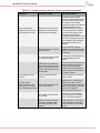
Maintenance and Troubleshooting ............................................................................ 55
9.1
9.2
9.3
Maintenance ............................................................................................................... 55
Recommended Care .................................................................................................. 55
Troubleshooting.......................................................................................................... 55
10 Warranty ................................................................................................................... 57
11 Support ..................................................................................................................... 58
v
®
WatchMaster IP Elite User Manual
TABLE OF FIGURES
Figure 1: Camera Hardware Overview ............................................................................................................ 4
Figure 2: IP Elite 3000 and 6000 Camera Rear View ..................................................................................... 5
Figure 3: WatchMaster IP Elite 3000 Range Data .......................................................................................... 8
Figure 4: WatchMaster IP Elite 6000 Range Data .......................................................................................... 9
Figure 5: Camera Components ..................................................................................................................... 10
Figure 6: Hardware Kit ................................................................................................................................... 10
Figure 7: Recommended Tool Kit .................................................................................................................. 13
Figure 8: Recommended Analog Tools ......................................................................................................... 13
Figure 9: IP66 with POE ................................................................................................................................ 14
Figure 10: IP66 with Ethernet and AC/DC Power ......................................................................................... 14
Figure 11: Analog and Ethernet Cable through the Gland ............................................................................ 15
Figure 12: Push Gland over the Cables ........................................................................................................ 15
Figure 13: Push Gland into Gland Housing ................................................................................................... 16
Figure 14: Tighten Gland Nut ........................................................................................................................ 16
Figure 15: Install Cables into Camera ........................................................................................................... 17
Figure 16: IP Elite 3000 & 6000 .................................................................................................................... 18
Figure 17: IP Elite Pin-Out ............................................................................................................................. 18
Figure 18: Possible Configurations of the IP Elite and IP Elite 3000 & 6000 ................................................ 19
Figure 19: POE with Power ........................................................................................................................... 19
Figure 20: Back Cover and White Desiccant................................................................................................. 19
Figure 21: Back Cover Screws and Sealing Washer .................................................................................... 20
Figure 22: Camera with Base Mount and Axis Mount ................................................................................... 20
Figure 23: Solar Shroud with Stem Bumpers ............................................................................................... 20
Figure 24: Fully Assembled Camera ............................................................................................................. 20
®
Figure 25: Camera mounted to a WatchMaster Wall Bracket ..................................................................... 21
Figure 26: Camera Discovery with Windows 7.............................................................................................. 22
Figure 27: Login Prompt ................................................................................................................................ 23
Figure 28: DRS Web Interface and Main Menu ............................................................................................ 25
Figure 29: DRS Web Interface Setup Menu .................................................................................................. 25
Figure 30: TCP/IP Settings ............................................................................................................................ 27
Figure 31: FTP Settings ................................................................................................................................. 28
Figure 32: Email Settings .............................................................................................................................. 29
Figure 33: Ping Target ................................................................................................................................... 29
Figure 34: 802.1X .......................................................................................................................................... 31
Figure 35: Zero Network Configurations ....................................................................................................... 31
Figure 36: User Accounts .............................................................................................................................. 33
Figure 37: Camera Date and Time settings .................................................................................................. 34
Figure 38: Video Streaming ........................................................................................................................... 36
Figure 39: Motion Detection .......................................................................................................................... 37
Figure 40: Video Settings .............................................................................................................................. 38
Figure 41: Pelco-D ......................................................................................................................................... 39
Figure 42: Analog Video Output .................................................................................................................... 40
Figure 43: Live Video and View Menu ........................................................................................................... 43
Figure 44: Motion Detection .......................................................................................................................... 45
Figure 45: Video Archive Menu ..................................................................................................................... 47
Figure 46: System Status .............................................................................................................................. 49
vi
®
WatchMaster IP Elite User Manual
Figure 47: Restart Camera ............................................................................................................................ 49
Figure 48: Restore Factory Defaults ............................................................................................................. 50
Figure 49: Formal Local Storage ................................................................................................................... 50
Figure 50: System Update ............................................................................................................................. 51
Figure 51: Heater Control .............................................................................................................................. 52
Figure 52: Auto Calibration Interval ............................................................................................................... 52
Figure 53: Constant Recording ..................................................................................................................... 53
vii
®
WatchMaster IP Elite User Manual
LIST OF TABLES
Table 1: Camera Hardware Components ........................................................................................................ 4
Table 2: Camera LED Indicators ..................................................................................................................... 5
®
Table 3: WatchMaster IP Elite Series Specification Quick Reference Table ................................................. 6
Table 4: WatchMaster® IP Elite 3000 Focus Information ............................................................................. 21
Table 5: WatchMaster® IP Elite 6000 Focus Information ............................................................................. 21
Table 6: Camera Main Menu and Access Privileges using the DRS Web Interface..................................... 24
Table 7: Network TCP/IP Settings ................................................................................................................. 26
Table 8: FTP Server ...................................................................................................................................... 27
Table 9: Email Server .................................................................................................................................... 28
Table 10: 802.1X ........................................................................................................................................... 30
Table 11: Accounts and Users ...................................................................................................................... 32
Table 12: Date and Time ............................................................................................................................... 33
Table 13: Video Streaming ............................................................................................................................ 34
Table 14: Motion Detection............................................................................................................................ 36
Table 15: Video Settings ............................................................................................................................... 38
Table 16: Pelco-D .......................................................................................................................................... 39
Table 17: Live Video and Controls ................................................................................................................ 41
Table 18: RTSP URIs .................................................................................................................................... 43
Table 19: Motion Detection............................................................................................................................ 44
Table 20: Video Storage and Recording ....................................................................................................... 46
Table 21: System Status ............................................................................................................................... 48
Table 22: Troubleshooting Symptoms, Causes and Recommendation ........................................................ 56
viii
®
WatchMaster IP Elite User Manual
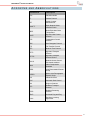
ACRONYMS AND ABBREVIATIONS
Abbreviation
Description
VOx
Vanadium Oxide
IP
Internet Protocol
ICE
Image Contrast
Enhancement
ONVIF™
Open Network Video
Interface Forum
NEDT
Noise Equivalent Delta
Temperature
DHCP
Dynamic Host Control
Protocol
TCP
Transmission Control
Protocol
UDP
User Datagram Protocol
FTP
File Transfer Protocol
NTP
Network Time Protocol
HTTP
Hypertext Transport
Protocol
HTTPS
Hypertext Transport
Protocol Secure
802.1X
Network Access Control
Port based standard
H264
Video Compression
Standard
JPEG
Joint Photographic Experts
Group
MJPEG
Motion Joint Photographic
Experts Group
VLC
VideoLAN Client
AGC
Automatic Gain Control
ROI
Region of Interest
RTP
Realtime Transport
Protocol
RTSP
Realtime Streaming
Protocol
UPnP
Universal Plug and Play
EULA
End User Licensing
Agreement
ix
®
WatchMaster IP Elite User Manual
REFERENCE DOCUMENTATION
The following documents form part of this user manual. In the event of a conflict between
documents referenced herein and the contents of this user manual
DRS WatchMaster® IP Elite Quick Start Guide
DRS WinXP UPnP Procedure
DRSWatchMaster® IP Family Interface Control document (ICD)
http://www.drsinfrared.com
DRS WatchMaster® IP Elite Training Videos --Please note these videos are applicable to
WatchMaster® IP Elite Cameras only. For training on all other models, please refer to the
above Quick Start Guide.
DRS WatchMaster® IP Elite Setup and Assembly
http://youtu.be/tFmwIowRWG8
Software Configuration Module 1 - DRS WatchMaster® IP Elite
http://youtu.be/Sx-TfdAD4D4
Software Configuration Module 2 - DRS WatchMaster® IP Elite
http://youtu.be/uXLsb5Fi99U
Software Configuration Module 3 - DRS WatchMaster® IP Elite
http://youtu.be/scxjOcVi4Ck
VLC Media Player Download (Version 2.0.0 Recommneded)
http://www.videolan.org/vlc/
x
®
WatchMaster IP Elite User Manual
SAFETY INSTRUCTIONS
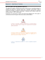
NOTIFICATIONS: CAUTION, WARNING AND NOTE
Throughout this manual, notifications are used to alert the user’s to potential risks and to
minimize the potential for personal injury and or damage to the product. When a
notification is present, it is important that the user review and understand all statements
related to the notification before proceeding. If questions arise, please contact your
authorized dealer or DRS Technologies.
Notifications are preceded by a symbol and followed by highlighted text. Three types of
notifications are used throughout this manual and are defined below:
CAUTION
A caution is a procedure, practice, or condition that, if not strictly followed,
may result in personal injury or damage to the equipment that may impede
product performance.
WARNING
A warning is intended to alert the user to the presence of potentially harmful
circumstances and provide precautionary guidance for mitigating risk of
personal injury and or damage to the product.
NOTE
A note is a statement that clarifies or is used to emphasize important
information.
xi
®
WatchMaster IP Elite User Manual
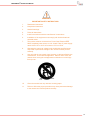
WARNING
IMPORTANT SAFETY INSTRUCTIONS
1.
Read these instructions.
2.
Keep these instructions.
3.
Heed all warnings.
4.
Follow all instructions.
5.
Install in accordance with the manufacturer’s instructions.
6.
Installation of the equipment must comply with local and national
electrical codes.
7.
This product must be connected to a Power Over Ethernet IEEE
802.af compliant power source or a UL Listed “Class 2” power supply
rated 12-24 V DC or 24 V AC minimum 13 W or 0.54 A.
8.
Operating the camera at voltage levels outside the specified range
may result in permanent damage to the unit and void the product
warranty.
9.
Use only with the cart, stand, tripod, bracket, or table specified by the
manufacturer, or sold with the apparatus. When a cart is used, use
caution when moving the cart/apparatus combination to avoid injury
from tip-over.
10.
Clean the camera lens only with lens cleaning paper.
11.
Failure to follow the proper procedure may cause permanent damage
to the camera and void the product warranty.
xii
®
WatchMaster IP Elite User Manual
This page intentionally left blank.
xiii
®
WatchMaster IP Elite User Manual
1
INTRODUCTION
1.1
DOCUMENT OVERVIEW
This document, provides details about the IP Camera features, installation, access,
configuration, application, interoperability, troubleshooting, warranty and support of the
DRS WatchMaster® IP Elite Fixed Mount, Fixed Focus Thermal IP and Analog Cameras.
This document also applies to the DRS WatchMaster® IP Elite Fixed Mount, Fixed Focus
Thermal IP Camera.
1
®
WatchMaster IP Elite User Manual
2
PRODUCT OVERVIEW
2.1
IP CAMERA OVERVIEW
This manual applies to the following products:
DRS WatchMaster® IP Elite 3000 30 Hz
DRS WatchMaster® IP Elite 3000 9 Hz
DRS WatchMaster® IP Elite 6000 30 Hz
DRS WatchMaster® IP Elite 6000 9 Hz
DRS WatchMaster® IP Elite 30 Hz
DRS WatchMaster® IP Elite 9 Hz
This chapter provides an overview of the DRS WatchMaster® IP Elite Series, a Fixed
Mount, Fixed Focus Thermal IP and Analog Camera. The DRS WatchMaster® IP Elite
Series offers a feature-rich thermal camera solution for video surveillance systems. The
DRS WatchMaster® IP Elite Series is available in 2 frame rates (versions), 30Hz and
9Hz. The WatchMaster® IP Elite Series employs DRS’s proven uncooled 320 x 240, 17
μm Vox thermal imaging technology. Unlike many conventional and low light video
surveillance cameras, the WatchMaster® IP Elite Series does not require any ambient
light or illumination. It detects infrared (heat) waves in the 8-12 µm wavelength in the
Electromagnetic spectrum to provide users with superior thermal images in challenging
environments, including complete darkness, over water and in dark corners, where
threats are difficult to detect due to lighting constraints and weather conditions.
The camera system is an Internet Protocol (IP) networked solution, conforming to the
Open Network Video Interface Forum (ONVIF™) standard and is operational in a
networked environment through a central office, remote video management system or
through the DRS provided web interface utility. With an industry leading low power
consumption of less than 12.95 watts, the WatchMaster® IP Elite is IEEE802.3af
compliant, supporting video, camera control and power over a single tamper resistant
cable connection. As a result, the camera can be configured and installed easily into any
existing security infrastructure.
Measuring approximately 29.2 x 10.4 x 9.5 cm and weighing less than 1500 grams, the
WatchMaster® IP Elite is compact and lightweight. It is sealed to an IP66 outdoor rating,
which makes it ideal for outdoor security of critical infrastructure such as airports, utility
companies, and nuclear power plants. The camera is available with a choice of three fully
sealed and hard carbon coated athermalized fixed focus lenses, which provide a
horizontal field of view of 40°, 24°, 16°, 9°, or 6° for Elite 3000 models and 44°, 37.5°,
24.8°, 17.6°, or 12.4° for Elite 6000 models, and are all capable of 4X digital zoom.
The Thermal IP camera includes the following key features:
Thermal Imaging – Provides superior thermal imaging capabilities in
complete darkness and challenging environments 24 hours a day 7 days a
week using patented DRS sensor technology.
Superior image quality with Image Contrast Enhancement (ICE) feature
2
®
WatchMaster IP Elite User Manual
Optimized Lens – The lens material and optical design is optimized for
thermal imaging and range performance.
Outdoor ready – Suitable for outdoor deployment out-of-the box with builtin heater anti-ice and anti-fog, and IP66 ready.
Local Storage – Comes with a built-in memory for storage of video
Power options – The IP camera can be powered with 12/24 volts DC or 24
volts AC, which is provided through an optional external power adapter, or
through PoE (802.3af), which is provided through a supported switch.
Communications Interface – 10/100 Ethernet and Power Over Ethernet
(POE).
DHCP support – The IP camera can automatically obtain its IP address in
a network in which DHCP is enabled.
Multiple protocol support –Supports DHCP, FTP, HTTP, HTTPS, NTP,
SMTP, RTP, RTSP, 802.1X, TCP/IP and UDP/IP.
H.264 and MJPEG compression – The camera can generate multiple
H.264 and MJPEG streams simultaneously, individually configurable with
streams up to 30 frames per second (fps) or fixed at 9 fps for export
simplification.
Multicast and user definable ports – Supports multicast IP address and
user definable ports for both H264 and MJPEG streams.
Web-based management – Administration and management of the IP
camera can be performed through the DRS web-based configuration
menus.
Motion detection – The IP camera can detect motion based on region of
interest definitions and can generate events/alerts if motion is detected.
Network Time Protocol (NTP) – Allows the IP camera to synchronize its
internal clock with a local or Internet time server.
Electronic Pan/Tilt and Zoom — The IP camera supports electronic pan &
tilt and digital zoom (4X).
Camera access control — You can control access to IP camera
configuration menus and live video by configuring various user types and
log in credentials.
Analog video output (NSTC/PAL) via BNC connection.
3
®
WatchMaster IP Elite User Manual
2.2
CAMERA HARDWARE
Physical details of the IP Camera is provided below.
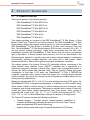
Figure 1: Camera Hardware Overview
Table 1: Camera Hardware Components
Item
Description
1
Camera Body
2
Base Mount
3
Back Cover
4
Solar Shroud
5
4 Hole Axis Mount Adapter (optional)
6
Cable Sealing Gland with electrical nut
7
Tamper Resistant Screws
8
Stem Bumpers
9
Desiccant
10
O-ring
11
Sealing Washers with Gasket
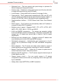
Figure 2 and Table 2 below describe the details of the rear of the camera.
4
®
WatchMaster IP Elite User Manual
Figure 2: IP Elite 3000 and 6000 Camera Rear View
Table 2: Camera LED Indicators
Item
Description
Network Port
Accepts a standard LAN cable to connect the IP camera to a
10/100Base Switch or Router.
LED
Indicates information about the network connections as follows:
Off – LAN connection is NOT detected
Solid Green - 100 MB LAN connection is detected
Solid Amber - 10 MB LAN connection is detected
Flashing Green/Amber - Data is being transmitted or received via
the LAN connection
Analog Video Connector
Accepts a standard BNC terminated coax cable for analog video
output. A 90-degree BNC adapter is also pre-installed on the
camera (not pictured above).
Power/RS-485 Connector
5-pin terminal block for power input – 2 for AC power input, 1 for
DC power input, 1 for Ground, and 2 for RS-485 connections.
12-24V DC or 24V AC power with minimum 13W or 0.54A and
10% tolerance.
Factory Reset Button
Reset button reboots the IP camera and resets it to the factory
default state. You can use a pin or paper clip to depress it and
hold for at least 20 seconds.
5
®
WatchMaster IP Elite User Manual
3
SPECIFICATIONS
3.1
QUICK REFERENCE SPECIFICATIONS
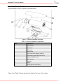
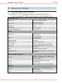
The WatchMaster® IP Elite Series Specifications are detailed below in Table 3.
Table 3: WatchMaster® IP Elite Series Specification Quick Reference Table
Focal Plane Array
Sensor Type
Uncooled VOx Microbolometer
Array Format
320x240 (3000 Series)
640x480 (6000 Series)
Pixel Pitch
17 µm
Spectral Band
8 - 14 µm (LWIR)
Sensitivity (NEDT) @ f/1.0
< 50 mK at f/1.0
Video
Frame Rate
Configurable for up to 30 Frames Per Second (fps)
or Fixed at 9 fps
Format
Analog: NTSC/PAL
IP: H264/MJPEG
Gain/Level Control
Automatic
4X Digital Zoom
1X-4X; 0.25X increments
Image Display
White Hot, Black Hot, Color, Invert/Revert
Symbology
On screen display with date, time, and user
defined text
Zoom
4x Digital Zoom with ePan/eTilt
Image Processing
Image Contrast Enhancement (ICE) for superior
performance
Communication Interface
™
Protocols
IP: ONVIF Conformant (v 2.0 / Profile S), RTP,
RTSP, TCP, UDP, DHCP, FTP, HTTP, and NTP
Analog: PELCO-D
Interfaces
IP: Ethernet (10/100 Base T), RJ-45
Analog: RS-485
Security
802.1X Network Access Control and HTTPS
Electrical
Voltage
12-24 V DC, 24V AC, 802.3af Power Over
Ethernet (PoE)
Power
<12.95 W with Heater
6
®
WatchMaster IP Elite User Manual
Environmental
Operating Temperature
-40°C to +60°C (-40°F to 140°F)
Storage Temperature
-50°C to +75°C (-58°F to +167°F)
Mechanical
Dimensions (L x H x W)
29.2 x 10.4 x 9.5 cm
Weight
< 1500 g
Enclosure
IP66, Tamper Resistant
Optics
Athermalized Fixed Focus Lens for Elite 3000
Horizontal Field of View (HFOV)
40°
24°
16°
9°
6°
f/no
1.2
1.0
1.1
1.2
1.2
7.5mm
13mm
19mm
35mm
50mm
Effective Focal Length
Athermalized Fixed Focus Lens for Elite 6000
Horizontal Field of View (HFOV)
44°
37.5°
24.8°
17.6°
12.4
f/no
1.2
1.2
1.2
1.2
1.2
14.25mm
16.7mm
25mm
35mm
50mm
Effective Focal Length
Software
DRS Web Interface
Administrator, Operator, and Viewer with
Password Protection
Hardware
Embedded Memory
2 GB for Video Storage and Image Capture
Approvals
Environmental/Enclosure
Electrostatic Discharge (ESD)
IEC 60529 IP66
FCC Part 15 Subpart B Class A, CISPR22 Class
B, EN55022 Class A
EN 61000-4-2 as modified by EN 55024
Electrical Fast Transients (EFT)
EN 61000-4-4 as modified by EN 55024
Radiated Disturbances
EN 61000-4-3 as modified by EN 55024
Conducted Disturbances
EN 61000-4-6 as modified by EN 55024
Power-Frequency Magnetic Fields
EN 61000-4-8 as modified by EN 55024
Emissions
7
®
WatchMaster IP Elite User Manual
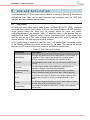
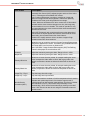
3.2
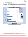
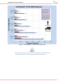
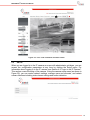
RANGE PERFORMANCE
The WatchMaster®IP Elite 3000 and 6000 range data assumptions and performance is
provided below. Typical detection and recognition range performance has been modeled
for multiple available lens solutions using NVTHERM1. See Figure 3 and Figure 4.
Figure 3: WatchMaster IP Elite 3000 Range Data
1
Lens transmission and MTF taken from actual design data; No LOS jitter; Atmospheric transmission is clear (90% at
1km), Detector sensitivity 30mK, System sensitivity 50mK; Probability of detection and recognition = 50%; Display:
nominal 640x480, 7.5” diag. flat panel with 2:1 interpolation of the 320x240 data. Viewing distance is 21". No Ezoom.
8
®
WatchMaster IP Elite User Manual
Figure 4: WatchMaster IP Elite 6000 Range Data
Data presented above are believed to accurately reflect camera performance
under stated conditions but are not guaranteed performance metrics.
9
®
WatchMaster IP Elite User Manual
4
INSTALLATION AND ACCESS
4.1
PACKAGE CONTENTS
When unpacking, please note any damage that may have occurred during shipping and
review the contents of the package to ensure all components are present. If any
discrepancies arise, please notify your authorized dealer or DRS Technologies directly.
The list of standard shipping contents is provided below.
WatchMaster® IP Elite Camera with the Back Cover attached and a brown
Desiccant pack inside the cover for shipping
o The WatchMaster® IP Elite 3000 and 6000 models also include a 90degree BNC Adapter already attached to the back of the camera
WatchMaster® IP Elite Camera Base Mount
WatchMaster® IP Elite Camera 4 Hole Axis Mount Adapter
WatchMaster® IP Elite Camera Solar Shroud
Hardware Kit with several small plastic bags containing
o
o
o
o
o
o
1 - Cable Sealing Gland with electrical nut
1 - O-Ring
16 - #6-32 X 5/8” screws including 2 spares
1 - White Desiccant for installation
3 - Sealing washers with gasket including 1 spare
3 - Stem Bumpers including 1 spare
1 – Power Block (4-pin: IP Elite, 5-pin: IP Elite 3000 and 6000) Quick Start
Guide
End User Licensing Agreement (EULA)
Figure 5: Camera Components
Figure 6: Hardware Kit
10
®
WatchMaster IP Elite User Manual
4.2
INSTALLATION
WARNING
Installation of the equipment must comply with local and national electrical
codes.
WARNING
This product must be connected to a Power Over Ethernet IEEE 802.af
compliant power source or a UL Listed “Class 2” power supply rated 12-24V
DC or 24V AC minimum 13 W or 0.54 A.
CAUTION
Operating the camera at voltage levels outside the specified range may result
in permanent damage to the unit and void the product warranty.
CAUTION
Failure to follow the proper procedure may cause permanent damage to the
camera and void the product warranty.
WARNING
DEVICE SENSITIVE TO ELECTROSTATIC DISCHARGE
The camera electronics and electronic interfaces are sensitive to electrostatic
discharge. Please follow appropriate ESD procedures when handling the
camera and during installation.
For PoE installations, DRS strongly
recommends the use of STP cabling and an earth grounded end point to
ensure proper ESD immunity. For AC or DC powered installations, a
properly earth grounded power source is strongly recommended.
11
®
WatchMaster IP Elite User Manual
CAUTION
To ensure a proper earth ground (between the DRS camera and a PoE
switch) DRS strongly recommends the use of Shielded Twisted Pair (STP)
cabling. Installations of DRS cameras using a STP cabling and a properly
earth grounded PoE switch are tested to comply with industry immunity
standards for Electro Static Discharge. Any other installation method may
leave the camera at risk and void the warranty.
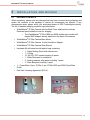
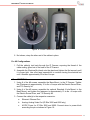
4.3
INSTALLATION PROCEDURE
The WatchMaster® IP Elite 3000 and 6000 Series can be configured for both Ethernet/IP
and Analog. The WatchMaster® IP Elite camera can be configured for Ethernet/IP only.
You will need the following recommended list of tools (not included) before you can install
the IP Camera.
Power source: PoE Switch, 12-24V DC or 24V AC
IP Network
Ethernet Cable (STP Cat5 recommended)
Tripod or Mounting bracket for mounting the IP Camera
A Phillips head #2 screwdriver
2 Open End Wrenches – 1 inch (25mm), OR adjustable wrenches
A 6-inch scale OR ruler
Torque screwdriver set to 10 inch-pounds (Electric or manual)
Torx (hole in the middle) T10 Pin-In Security bit – 3.5 inch (90mm) in
Length
Hex Wrench
RJ-45 connecter and
RJ-45 Crimping Tool
Suggested Tools for Analog Video (IP Elite 3000 and 6000 only):
o Coax Cable
o Coax Cable Cutter/Stripper
o BNC Connector
o BNC Crimping Tool
12
®
WatchMaster IP Elite User Manual
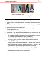
Figure 7: Recommended Tool Kit
4.4
Figure 8:
Recommended
Analog Tools
PREPARING THE CABLE
1. Disconnect power from the exposed cable(s) of the standard Bracket.
2. Take the number 2 Phillips head screwdriver and pierce the membrane of the cable
gland.
3. If needed, pierce 2 smaller holes on the membrane of the cable gland for AC/DC
power wires.
4. Remove the electric nut from the sealing gland.
5. Place the O-ring (Orange) on the threaded end of the cable gland. This is necessary
to insure a good seal for IP66.
6. Cut off the RJ-45 connector if using existing Ethernet cable.
7. Feed existing or new cable(s)from the standard Axis or Pelco Bracket through the
components in the following order:
a. 4 Hole Mount Adapter (4 hole flat surface facing the mating bracket) if required
b. 3 Hole Base Mount (Flat side first for mating 3 Hole Bracket)
c. Electrical Nut (Convex side) of the supplied Cable Sealing Gland
d. Bottom of the IP Camera body through the back hole below the connectors
Securing for IP66 (POE only)
1. Slide the Ethernet cable through the threaded end of the cable sealing gland, with
Orange O-Ring installed.
2. Measure approximately 4.5 inches of cable slack from the end of the cable to the
rubber grommet of the sealing gland. Use a scale to measure the length.
3. Attach one open end wrench onto the flange of the cable gland and tighten the
compression nut, with the second open wrench, to approximately 50-55 in-lbs. of
torque
4. Assemble a new RJ45 head to the Cat 5 Ethernet Cable
13
®
WatchMaster IP Elite User Manual
Figure 9: IP66 with POE
Securing for IP66 (Ethernet & AC/DC power):
1. Slide the Ethernet cable through the threaded end of the cable sealing gland, with
Orange O-Ring installed.
2. Slide the 2, 20 AWG power wires through the back side of the cable sealing gland.
3. Measure approximately 4.5 inches of cable slack from the end of the cable to the
rubber grommet of the sealing gland. Use a scale to measure the length.
4. Attach one open end wrench onto the flange of the cable gland and tighten the
compression nut, with the second open wrench, to approximately 50-55 in-lbs. of
torque.
5. Assemble a new RJ45 head to the Cat 5 Ethernet Cable.
6. Assemble a mating power connector to the 2 AC or 2 DC power cables.
Figure 10: IP66 with Ethernet and AC/DC Power
Securing for IP66 (Analog & AC/DC Power – IP Elite 3000 and 6000 Only)
1. Slide the Coax cable through the threaded end of the cable sealing gland, with
Orange O-Ring installed.
2. Slide the 2, 20 AWG power wires (and any RS-485 wires) through the back side of
the cable sealing gland.
3. Measure approximately 4.5 inches of cable slack from the end of the cable to the
rubber grommet of the sealing gland. Use a scale to measure the length.
14
®
WatchMaster IP Elite User Manual
4. Attach one open end wrench onto the flange of the cable gland and tighten the
compression nut, with the second open wrench, to approximately 50-55 in-lbs. of
torque.
5. Assemble a new RJ45 head to the Cat 5 Ethernet Cable.
6. Assemble a mating power connector to the 2 AC or 2 DC power cables (and RS485 cables if used).
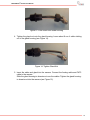
Securing for IP66 (Analog & Ethernet – IP Elite 3000 and 6000 Only)
1. Put the nut onto the cables first. And then push the analog video cable and CAT5
cable through the gland (see Figure 11). The CAT5 cable goes through the center.
The analog video goes through one of the 5 outer holes.
Figure 11: Analog and Ethernet Cable through the Gland
2. Push the gland housing over the cables (see Figure 12).
Figure 12: Push Gland over the Cables
3. Push the gland rubber into the gland housing (See Figure 13)
15
®
WatchMaster IP Elite User Manual
Figure 13: Push Gland into Gland Housing
4. Tighten the gland nut onto the gland housing. Leave about 8 cm of cable sticking
out of the gland housing (see Figure 14).
Figure 14: Tighten Gland Nut
5. Insert the cable and gland into the camera. Connect the Analog cable and CAT5
cable to the camera.
Slide the gland housing-to-chassis nut over the cables. Tighten the gland housingto-chassis nut into the camera (see Figure 15).
16
®
WatchMaster IP Elite User Manual
Figure 15: Install Cables into Camera
6. Not shown, crimp the other end of the cables in place.
For All Configurations
1. Pull the cable(s) taut back through the IP Camera, exposing the thread of the
cable sealing gland out of the base of the IP Camera.
2. Assemble the Electrical Nut back onto the gland and tighten the Nut securely until
it is finger tight. Use a flat head screwdriver to continue turning the electrical nut
until it reaches approximately 50 in-lbs of torque.
4.5
ASSEMBLY
1. Using 8 of the #6 screws, assemble the Base Mount, to the IP Camera. Tighten
the 8 fasteners to approximately 10 in-lbs. of torque with the Electric Screw Driver,
and T10 Security bit.
2. Using 4 of the #6 screws, assemble the optional Standard 4 hole Mount, to the
Base Mount, and tighten the fasteners to approximately 10 in-lbs. of torque with
the Electric Screw Driver, and T10 Security bit.
3. Connect the cable(s) to the respective connector:
a.
Ethernet: Ethernet Port
b.
Analog: Analog Video Out (IP Elite 3000 and 6000 only)
c.
AC/DC Power for IP Elite 3000 and 6000: Connect wires to power block
according the pin-out shown in Figure 16:
17
®
WatchMaster IP Elite User Manual
i. If powering the camera with an AC supply, connect AC+ to the 24VAC
input and the AC- to the 12VDC input
ii. If powering the camera with a DC supply, connect the DC+ to the
12VDC input and the DC- (or ground) to the GND input.
Figure 16: IP Elite 3000 & 6000 Pin-Out
Pins 1-3: Power (GND, 24V AC, 12-24 DC or 24V AC)
Pins 4-5: RS-485 (POS, NEG)
d.
AC/DC Power for IP Elite: Connect wires to power block according the pinout shown in Figure 17:
i. If powering the camera with an AC supply, connect AC+ to the 24VAC
input and the AC- to the other 24VAC input
ii. If powering the camera with a DC supply, connect the DC+ to the
12VDC input and the DC- (or ground) to the GND input.
Figure 17: IP Elite Pin-Out (24V AC, 24V AC, 12V DC, GND)
4. RS-485: Connect wires to power block according to the pin-out shown in Figure 16.
18
®
WatchMaster IP Elite User Manual
a. Connect the RS-485+ pin to the camera’s POS and connect the RS-485- pin to
the camera’s NEG pin.
5. Reconnect Power to the existing cable(s).
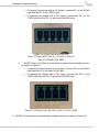
6. Check for Solid LED on the Ethernet connector to acknowledge connectivity to the IP
network. The status LED indicators are:
a.
LED 1: Solid Amber for 10MB connection
b.
LED 2: Solid Green for 100MB connection or Flashing Green for Activity
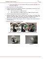
7. Place the supplied white desiccant into the Back Cover.
8. Assemble the Back Cover to the IP Camera using 2, #6 screws and 2 Master Seal
Washers (metal size against the head of the screw and gasket side against the
camera body). Tighten the 2 fasteners to approximately 10 in-lbs. of torque.
9. Assemble the 2 Rubber Stem Bumpers onto the 2 detents in the concave surface of
the Solar Shroud.
10. Snap the Solar Shroud to the Base Mount.
Figure 18: Possible Configurations of the IP Elite and IP Elite 3000 & 6000
Figure 19: POE with Power
Figure 20: Back Cover and White
Desiccant
19
®
WatchMaster IP Elite User Manual
Figure 21: Back Cover Screws and Sealing
Washer
Figure 22: Camera with Base Mount and
Axis Mount
Figure 23: Solar Shroud with Stem
Bumpers
Figure 24: Fully Assembled Camera
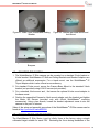
4.6
MOUNTING THE CAMERA
1. The WatchMaster® IP Elite camera can be mounted on a standard 3-hole bracket or
4-hole bracket. WatchMaster® IP Wall and Ceiling Brackets and Bracket Adaptors are
offered as additional accessories. For a tripod mount, use the WatchMaster® IP
Tripod Adapter which is also offered as an accessory.
2. For standard 3-hole mount, secure the Camera Base Mount to the standard 3-hole
bracket (not provided) using #1/4-20 screws (not provided).
3. For a standard 4-hole mount and , first secure the optional 4-hole mount adapter to
the base mount.
4. Position the assembled Camera’s 4-hole mount adapter onto the bracket and tighten
the Metric M5 Screws (provided only with official WatchMaster® mounting
accessories). Using a hex wrench, loosen the bracket adjustment screw to aim the
camera to the point of interest.
Video of the setup and assembly procedure of the WatchMaster® IP Elite camera can be
found at http://youtu.be/tFmwIowRWG8
4.7
MANUAL FOCUS AND FOCUS TOOL
The WatchMaster IP Elite Series is set to infinity focus at the factory using a simple
collimated target suitable for each FOV. Reviewing the focus during installation of the
20
®
WatchMaster IP Elite User Manual
camera is recommended for optimal image quality so necessary adjustments suitable for
the environment and the target object can be made. All lenses for eachfield of view can
be focused manually by hand. Make sure not to touch the lens when adjusting the focus.
However, the 40° lens may require the use of a focus tool. The focus tool is available
from DRS as an optional accessory item. For ordering details, please refer to the DRS
WatchMaster IP Elite 3000 price sheet.
Table 4: WatchMaster® IP Elite 3000 Focus Information
FOV
40º
Effective Focal Length
7.5mm
f/#
1.2
24º
13mm
1.0
16º
19mm
1.1
9º
35mm
1.2
6º
50mm
1.2
Table 5: WatchMaster® IP Elite 6000 Focus Information
FOV
44º
Effective Focal Length
14.25mm
f/#
1.2
37.5º
16.7mm
1.2
24.8º
25mm
1.2
17.6º
35mm
1.2
12.4º
50mm
1.2
The camera is now ready for use!
Figure 25: Camera mounted to a WatchMaster® Wall Bracket
21
®
WatchMaster IP Elite User Manual
4.8
ACCESS
After installing the WatchMaster™ IP Elite Camera, you can access the IP Camera to
make configuration changes and view live video using the DRS Web Interface. In order to
make these changes, you can connect to the IP Camera from any PC on your network.
The PC must meet below minimum requirements:
OS - Microsoft Windows 7 or Windows XP or Windows Vista
Browser - Internet Explorer 9.0, Mozilla Firefox 8.0, and Google Chrome 29
VLC Media Player Software (2.0.0 recommended) – can be downloaded from the
DRS IP Elite Camera directly through the DRS Web Interface or from
http://www.videolan.org/vlc/
CAMERA DISCOVERY AND IP ADDRESS
To connect to the IP camera for the first time and make initial configuration settings, the
IP address must be discovered. It is recommended that the camera have access to a
router with a DHCP server to enable automatic assignment of the IP Address
corresponding to the MAC address of the camera. The procedure for this is network
specific, but a device list usually exists on the router.
By default, when the IP camera powers on, it attempts to obtain an IP address from a
DHCP server on the network. If the camera cannot obtain an IP address through DHCP
within a reasonable time, it will default to an IP address of 192.168.0.200 and a subnet
mask of 255.255.255.0.
In the event that the installer does not have access to the DHCP server, the Windows
Network tool can be used to locate the camera. The below instructions can be used for
Windows 7 and Windows XP.
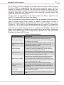
Windows 7 OS:
Click on Start, Click on Computer and Click on Network. A list of devices
connected to your network will appear as below. Double Click on the name (DRS
WM IP Elite) of the camera to launch the default browser. You can see the IP
address of the camera in the Browser URL.
Figure 26: Camera Discovery with Windows 7
22
®
WatchMaster IP Elite User Manual
Windows XP OS:
The procedure for discovering the IP address of the camera using Windows XP
requires activation of Universal Plug and Play (UPnP) service. Further details
can be found in the DRS WinXP UPnP procedure document.
ONVIF™ discovery tools or other 3rd party tools may also be used to discover the
camera.
4.9
LOGIN TO THE IP CAMERA
1. Enter the IP address of the IP Camera on the Browser URL line.
2. Enter the default username and password when prompted (see Figure 27).
Figure 27: Login Prompt
3. Default username and password are given below for Administrator access:
(lower case)
Username is
Password is
admin
1234
If you have not downloaded the VLC Media Player by this time, you can download it from
the Camera. After login to the IP Camera, follow the prompt at the bottom of the screen to
install the VLC Media Player. The minimum required VLC Media Player version is 1.1.10.
4.10
LOG OUT
To log out of the IP Camera, click on the Log Out link in the main menu or click on the
Log Out link at the bottom of the screen.
23
®
WatchMaster IP Elite User Manual
5
CONFIGURATION AND MANAGEMENT
The WatchMaster® IP Elite Series is an Internet Protocol (IP) networked solution, and is
operational in a networked environment through a central office, remote video
management system or through the DRS provided Web Interface. This section covers the
configuration and management of the IP camera using the DRS Web Interface.
5.1
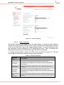
DRS WEB INTERFACE AND ACCESS PRIVILEGE
After you log in to the WatchMaster® IP Elite Series Camera, you can access the different
menus (as shown in Figure 28) and perform administrative and user actions using the
DRS Web Interface. Administrators can access all of the IP camera menus, features and
functions. Operators have access to limited IP camera menus, features and functions.
Viewers can only view live video and access image controls. Main menus and access
level details are provided in Table 6 below.
Table 6: Camera Main Menu and Access Privileges using the
DRS Web Interface
Main Menu
Description
Access Privilege
View
Live video and image controls
Administrator
Operator
Viewer
Motion Detection
Region of Interest selection and
Motion Detection Settings
Administrator
Operator
Video Storage
Recording and Storage of video
and images
Administrator
Operator
Maintenance
System updates, Camera reset,
Factory default,
Administrator
Setup
IP Network settings, user and
account management and
camera controls
Administrator
Logout
Log out of the camera
Administrator
Operator
Viewer
24
®
WatchMaster IP Elite User Manual
Figure 28: DRS Web Interface and Main Menu
5.2
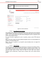
SETUP
When you are logged in to the IP camera as a user with administrator privileges, you can
access the configuration parameters at any time by clicking the Setup menu. For
information about logging in to the IP camera, see Section 4.9 “Login to the IP Camera”.
This section covers the setup of the camera. Using the camera setup menu (as shown in
Figure 29), you can control network settings, manage users and accounts, and certain
camera functions including video stream settings and motion detection.
Figure 29: DRS Web Interface Setup Menu
25
®
WatchMaster IP Elite User Manual
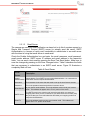
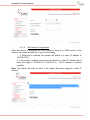
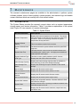
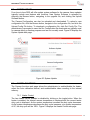
5.2.1 Network Setup
The network Setup pages allows the administrator to configure the camera’s network
settings and configure specific network features. To access the Network Settings, the
user must have administrative privileges.
5.2.1.1
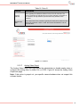
TCP/IP Settings
Table 7 and Figure 30 below provide details on configuring the TCP/IP network settings
of the camera. These settings will remain saved on firmware upgrades from version
1.2.3238 onward.
Table 7: Network TCP/IP Settings
TCP/IP
Settings
Description
DHCP
Select the method by which the IP camera obtains its IP address:
Dynamic — Choose this option if your network includes a DHCP server for
dynamic allocation of IP addresses. Make sure the DHCP server assigns IP
address, subnet mask, default gateway and DNS server addresses.
The camera will attempt to connect to the network for ~ 5 minutes after 5
minutes, if no DHCP connection can be established, the camera will either fall
back to the default IP address (192.168.0.200) or obtain a Zero Network Config
assigned IP address (if Zero Network Config is enabled)
Static IP
Address
Static — Choose the DHCP option NO if you want to manually enter the IP
address and enter the IP address for the camera.
Subnet
Mask
If you configured the IP camera for a static IP address, enter the subnet mask
for the IP camera. Use the same value that is configured for the PCs on your
network.
Gateway
If you configured the IP camera for a static IP address, enter the gateway for
the IP camera. Use the same value that is configured for the PCs on your
network.
DNS
Server
Enter the IP address of the DNS server that is used in your network. Use the
same value that is used for the PCs on your LAN.
Host Name
Default name is DRS WM IP Elite <MAC Addr>. Enter a nickname for the IP
Camera, if desired.
26
®
WatchMaster IP Elite User Manual
Figure 30: TCP/IP Settings
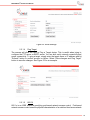
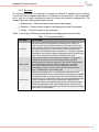
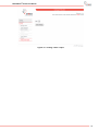
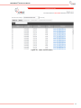
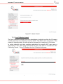
5.2.1.2 FTP Server
FTP server may be used for receiving events/alerts triggered by camera motion detection
and for storing recorded video images and files. The FTP, or the File Transfer Protocol,
makes it possible for users to exchange files between the camera’s FTP client and a
remote FTP server. The FTP configuration allows the administrator to establish a
connection with a remote machine of their choice. The FTP connections are executed
through certain ports, which are either the default TCP ports or custom ports set by an
administrator. Once configured, the camera will download motion video files to the FTP
server; this allows for a large amount of video storage.
Enter the FTP Server address, FTP port, FTP user name, ftp password, and the ftp path
name which is a default folder in the ftp server. See Table 8 and Figure 31for
configuration details and an example configuration.
Table 8: FTP Server
FTP
Server
Description
FTP Server
The FTP Server is the IP address of the FTP server used to upload your files.
FTP Port
To establish an FTP session, clients initiate a connection to an FTP server that
listens on TCP port 21 by default. FTP servers respond with messages that
prompt the client for FTP login credentials (username and password).
Username
The User Name is the name of the FTP account you use to upload the files.
Password
This is the password associated with the Username above.
FTP Path
The FTP Path (also known as the "root" Web folder) is the specific folder in your
Web hosting server space that contains all Web-related files (such as html and
image files).
27
®
WatchMaster IP Elite User Manual
Figure 31: FTP Settings
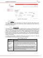
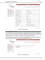
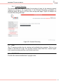
5.2.1.3
Email Server
The camera can send you email notification on alarm but to do this it requires access to a
Simple Mail Transport Protocol (SMTP) server (to actually send the email). SMTP
Authentication is a means of using one's credentials to authenticate to an email server
with the intent of using that email server to send email.
Check the Enable Authentication box and enter the email username, email password,
email sender address, SMTP server IP address and email address in the respective
fields. You can send a test email by pressing the Send Test Email button. Make sure to
save the changes by pressing on the Save Changes button. Table 9 describes the fields
that are necessary to authenticate to an SMTP email server. Figure 32 illustrates a
completely filled out form.
Table 9: Email Server
Email
Server
Description
Enable
Authentication
Check this box if your SMTP server requires Authentication. As a general rule
most SMTP servers required authentication.
Username
The Username is the name that was used to set up the email server account.
Password
This is the password associated with the Username above.
Email Sender
Is your domain email address. This is the address used to send your Internet
email. This address will appear in the “From” portion of the email
SMTP Server
The SMTP server is the outgoing mail server through which you send your
outgoing mail. Since you are connected to your Internet Service Provider (ISP),
they know that you are a valid subscriber and allow your outgoing email to be
relayed to the destination.
Email To
This is the address used to receive your Internet email. This address will
appear in the “To” portion of the email
28
®
WatchMaster IP Elite User Manual
Figure 32: Email Settings
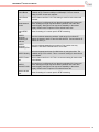
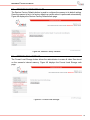
5.2.1.4
Ping Target
The camera will allow the user to Ping a Target device. This is useful when trying to
configure the FTP server or SMTP server. You can both verify network connectivity and
server connectivity. To ping a target, simply enter the target name or IP address and hit
“Refresh” button to confirm success or failure. Select “Save changes and Ping Target”
button to save the changes. See Figure 33 for an example.
Figure 33: Ping Target
5.2.1.5
802.1X
802.1x is an IEEE standard specifying port-based network access control. Port-based
network access control uses the physical characteristics of a switched local area network
29
®
WatchMaster IP Elite User Manual
(LAN) infrastructure to authenticate devices that are attached to a LAN port and to
prevent access to that port in cases in which the authentication process fails.
During a port-based network access control interaction, an authentication server (which
can either be a separate entity or co-located with the authenticator) checks the camera’s
credentials. The authentication server then responds to the authenticator, indicating
whether the camera is authorized to access the authenticator's services.
Extensible Authentication Protocol (EAP) is used to pass the authentication information
between the camera and the authentication server. The actual authentication is defined
and handled by the EAP type. The EAP Type selected is based upon how the
authentication server is configured.
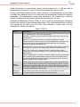
Table 10: 802.1X
802.1X
Description
EAP Type
Off – Disables 802.1X. This is the default setting
EAP-MD5 - is typically not recommended because it provides for only one way
authentication
EAP-GTC - uses clear text method to exchange authentication controls
between the camera and the server. Since the authentication mechanism uses
the one-time tokens (generated by the servers smartcard), this method of
credential exchange is considered safe.
EAP-MSCHAPV2 – Requires that the authentication server present a certificate
to the camera. This protocol is used primarily in Microsoft Active Directory
EAP-TTLS - This security method provides for certificate-based, mutual
authentication of the client and network. You must upload a Certificate via the
Browse button.
PEAPv0—MSCHAPV2 - Provides a method to transport securely authentication
data, including legacy password-based protocols. PEAP accomplishes this by
using tunneling between the camera and an authentication server. You must
upload a Certificate via the Browse button.
Server
Certificate
Points to the location of the server certificate. Enter the Path and folder where
the root certificate that is required for 802.1x authentication is stored. You can
click browse to find this location. After you enter this information, click Upload
Certificate to upload the certificate to the IP camera. Note; used for EAP-TTLS
and PEAPv0-MSCHAPV2 authentication.
Username
The Username is the name that was used to set up the 802.1x account.
Password
This is the password associated with the Username above.
30
®
WatchMaster IP Elite User Manual
Figure 34: 802.1X
5.2.1.6
Zero Network Configuration
When the camera is configured as DHCP mode but there is no DHCP server on the
network, the camera will fall back to one of the following:
1. If Zeroconfig is disabled, the camera will default to a static IP address of
192.168.0.200
2. If Zeroconfig is enabled, the camera will default to a static IP address that is
within the range of 169.254.0.0 to 169.254.0.16. The IP address is selected
randomly.
Note: This feature will have no affect if the camera has been assigned a static IP
address.
Figure 35: Zero Network Configurations
31
®
WatchMaster IP Elite User Manual
5.2.2 Accounts
For security purposes it is important to change the default IP address of your camera
once it has been configured and before it is placed into a live network. This is especially
true if you do not want unauthorized users to change the camera configurations. The
camera offers the following authorization levels:
1. Administrator – Has full access to the camera’s web pages
2. Operator – Does not have access to the Maintenance and Setup pages
3. Viewer – Only has access to the view page
Table 11 and Figure 36 below provide details on managing accounts and users.
Table 11: Accounts and Users
Accounts
Description
New users
New user accounts can be created for accessing the IP camera. To
create a new account, go to the account menu and enter the new user
name, select the user class (Administrator, Operator or Viewer) from the
User Class drop down menu, enter and confirm the password for the
user. Click on the Add User button to add the user. You will see a prompt
confirming the user has been added. Repeat this process for adding more
users. User name and user class will be updated in the menu.
Existing users
Existing user accounts can be managed and modified. To change the
password for an existing user, enter a new password in the New
Password field and reenter the password in the Confirm Password field.
Click on Update User button to update the password. To assign a
different user class to the user, select the appropriate user class
(Administrator, Operator or Viewer) from the User Class drop down
menu. To delete users, click on delete users.
Onvif Security
Enabling and disabling Onvif™ user authentication allows for better
interoperability between Onvif™ Clients that don’t fully support the WSSE
security model. While we recommend that you leave this option enabled
and provide Onvif™ clients with the same user name and password used
to login to an admin account on the web interface, disabling Onvif™
security may resolve some issues that arise when clients fail to properly
authenticate themselves. Note: Since WSSE uses the current time as
part of its security model, the proper time must be set both on the camera
and the Onvif™ client software.
32
®
WatchMaster IP Elite User Manual
Figure 36: User Accounts
5.2.3 Camera
The Camera pages allow the administrator to configure the camera’s video settings, time,
and video analytic settings. To access the camera settings, the user must have
administrative privileges.
5.2.3.1
Date and Time
The Date and Time web page allows the administrator to configure an external NTP time
server for automatic time setting or manually set the time and time zone (as described in
Table 12). The camera does not have a battery backup and will default back to the
software build date following a power cycle. If the manual setting is used or the camera
cannot connect to the NTP server, the camera time is set to the software build date. If
NTP is enabled and the camera connects to an NTP server, the camera will automatically
update it’s time setting.
It is highly recommended to enable the NTP server (as shown in Figure 37). This will
ensure that the camera logs have the correct time information.
Table 12: Date and Time
Date and
Time
Description
NTP Server
Settings
NTP time clock can also be over written manually if necessary in the
Camera –Date/Time menu. Enter date/time, select the time zone and
enable Daylight savings if needed. Confirm by pressing the Set Date and
Time button.
Manual Time
Settings
If NTP isn’t desired or is unavailable, date/time can be manually edited
here. Select the time zone and enable Daylight savings if needed.
Confirm by pressing the Set Date and Time button. NOTE: NTP must be
disabled above in order to save changes.
33
®
WatchMaster IP Elite User Manual
Figure 37: Camera Date and Time settings
5.2.3.2
Video Streaming
The Video Streaming web page allows the administrator to configure and adjust a wide
range of H.264, MJPEG, or HTTP JPEG streaming methods; these are used to optimize
the video stream for bandwidth, network configuration, quality, and compatibility with
other decoders and video players. Table 13 provides details on the video streaming
options and Figure 38 shows an example.
DRS uses a Constant Variable Bit Rate (CVBR) rate control implementation which allows
the bitrate to change in a given time interval based on the complexity of the scene. The
CVBR implementation automatically adjusts the average, min and max bitrate based
upon the network conditions.
Note: If the camera is connected to a heavily congested network or connected via a
wireless network, it is highly recommended to set the H.264 bitrate to ~ 500Kbps and/or
adjust the MJPEG quality to ~ 50%.
Table 13: Video Streaming
Video
Streaming
Description
Enable
Multicast
Streaming
Check this box to select multicast streaming. Make sure your network
supports multicasting. Leave the box as unchecked for unicast streaming.
The default is unicast streaming.
H264 Multicast
Streaming IP
Address
Enter the multicast streaming address. Valid range for multicast IP
address is between 224.0.0.0 and 239.255.255.255. Typical multicast IP
address is 239.x.y.z
H264 Multicast
Streaming Port
Enter the multicast streaming port number. Port number can vary
between 1 and 65535. Default value is set to 554.
34
®
WatchMaster IP Elite User Manual
H.264 Bitrate
Select the appropriate bit rate for H264 video by using the slider. The
available range is between 64Kbps to 2500Kbps. This is a common
setting for both unicast and multicast.
H.264 Frame
rate
Select a frame rate from 5-30. This setting is used for both unicast and
multicast.
H264 Network
Cache
Amount of time in milliseconds (ms) that the embedded VLC player will
cache. Settings too high may cause latency between live action and
stream display. Settings too low may cause instability in the stream
display. Default value is optimum for the default frame rate.
H.264 RTSP
Port
Allows for setting of a custom port for RTSP streaming.
MJPEG
Multicast
Streaming IP
Address
Enter the multicast streaming address. Valid range for multicast IP
address is between 224.0.0.0 and 239.255.255.255. Typical multicast IP
address is 239.x.y.z
MJPEG
Multicast
Streaming Port
Enter the multicast streaming port number. Port number can vary
between 1 and 65535. Default value is set to 6001.
MJPEG Quality
Select the appropriate bit rate for H264 video by using the slider. The
available range is 5% to 98%. This is a common setting for both unicast
and multicast.
MJPEG Frame
rate
Select a frame rate from 1-30. This is a common setting for both unicast
and multicast.
MJEPG
Network Cache
Amount of time in milliseconds (ms) that the embedded VLC player will
cache. Settings too high may cause latency between live action and
stream display. Settings too low may cause instability in the stream
display. Default value is optimum for selected frame rate.
MJPEG RTSP
Port
Allows for setting of a custom port for RTSP streaming.
35
®
WatchMaster IP Elite User Manual
Figure 38: Video Streaming
5.2.3.3
Motion Detection
The Motion Detection web page allows the administrator to determine what happens
if/when the camera detects a motion event. Keep in mind that the administrator must set
up the motion detection rules on the motion detection page. If no motion detection rules
are configured, no mail notifications or FTP downloads will occur. Table 14 describes the
different options which are available and Figure 39 shows an example.
It is highly recommended to enable the NTP server (as shown in Figure 37). This will
ensure that the camera logs have the correct time information.
Table 14: Motion Detection
Date and
Time
Description
Send Event to
FTP Server
Check this box to send motion events to the FTP server. The
administrator must configure the FTP Server in order for this feature to
work correctly.
Media Type for
FTP Upload
Select to include either a MJPEG video clip or JPEG still image to the
FTP server.
Send email
notification
Check this box to send email notification of motion events. The
administrator must configure the SMTP Server in order for this feature to
work correctly.
Media Type for
email
Notification
Select to include either a MJPEG video clip or JPEG still image as part of
the email.
36
®
WatchMaster IP Elite User Manual
Save Event
Video to Local
Analytics
Folder
Check this box to save events to a local folder.
Figure 39: Motion Detection
5.2.3.4
Server Based Video Analytics
Server Based Video Analytics is a special MJPEG framing mode which transmits both the
standard MJPEG video data and full dynamic range video data within the same MJPEG
frame. As the name implies this video mode is designed to work in conjunction with
specific video analytics servers.
For more information regarding this mode of operation, please contact DRS technical
support.
Note: This option requires third party software integration and is not recommended to be
enabled if not actively being used.
Note: If this option is grayed out, your specific camera hardware does not support this
software feature.
5.2.3.5
Video Settings
The Video Settings web page allows the administrator to select the Color Palette and Onscreen display of time, date, and arbitrary text (which is overlaid onto the screen). The
Color Palette selects the current color lookup palate used by the camera to colorize the
grayscale image. Options include: White Hot, Black Hot, Red Light, Arcus, Inferno,
SoftLight, Sunset, InMemoriam, Flamma Articus, Oceanus, Rain, and a Vendor Defined
palette
37
®
WatchMaster IP Elite User Manual
Note: If this option is grayed out, your specific camera hardware does not support this
software feature.
Table 15: Video Settings
Video
Settings
Description
Select Color
Palette
The gray scale IR images are mapped to a number of color palettes. In
different applications, a user may find a specific color palette easier to
view or more desirable to watch. Often times a color palette will provide
some more detail to the scene.
Show Date
Overlays the cameras date in the bottom right corner of the image/video.
The cameras date and time must be configured via the data and time
page
Show Time
Overlays the cameras time in the bottom right corner of the image/video.
The cameras date and time must be configured via the date and time
page
OSD Text
Overlays text in the upper left corner of the image/video. The Text can be
a maximum of 24 characters.
Figure 40: Video Settings
5.2.3.6
Pelco-D
Pelco-D is a popular PTZ (Pan/Tilt/Zoom) camera control protocol used in the CCTV
industry. The Pelco-D web page allows the administrator to configure the Pelco-D
address and baud rate.
Note: If this option is grayed out, your specific camera hardware does not support this
software feature.
38
®
WatchMaster IP Elite User Manual
Table 16: Pelco-D
Pelco-D
Description
Pelco-D
Address
This is typically the hardware address for the Pelco-D controller. The
Pelco-D controller will typically have a set of dip switches on the back of
the controller; the dip switches represent the binary address of the
controller.
RS485 Baud
Rate
This is baud rate of the controller; typically the baud rate is printed on the
back of the controller. If Auto is used, the camera will attempt to use all
the baud rates
Figure 41: Pelco-D
5.2.3.7
Analog Video Output
The Analog Video Output web page allows the administrator to disable analog video or
configure the analog video for either PAL or NTSC. Figure 42 shows the Analog Video
Output web page.
Note: If this option is grayed out, your specific camera hardware does not support this
software feature.
39
®
WatchMaster IP Elite User Manual
Figure 42: Analog Video Output
40
®
WatchMaster IP Elite User Manual
6
USE AND APPLICATION
The WatchMaster® IP Elite camera can be used for a variety of Security & Surveillance
Applications. Live video can be easily accessed and managed using the DRS Web
Interface and most standard web browsers.
6.1
LIVE VIDEO
All users can view video, select video stream (H264/MJPEG/HTTP JPEG), configure
Automatic Gain Control (AGC) mode, ICE Level (for Indoor/Outdoor ICE AGC settings),
image polarity (black hot, white hot), flip images, adjust the zoom, and control
contrast/brightness of the Camera. Table 17 describes each of the features that are
available to all users. Figure 43 shows a typical View screen shot. In this screen shot,
one can see that the H.264 video is being recorded, Auto AGC mode is selected, the
eZoom is set for 2.25, and white hot mode is selected.
A VLC media player is required to view live video. VLC media player is available as part
of the Camera software and can be downloaded by the users. The camera will prompt
the user for VLC download when the camera is accessed for the first time.
Table 17: Live Video and Controls
Live Video
Description
Video Stream
Select the appropriate video stream H264, MJPEG, or HTTP JPEG. It
is possible to select multiple video streams from a single camera.
However, separate browser windows are required to do this.
Snapshot
Takes a Snapshot of the image. The user can save the image to the
local PC.
View Size
The video viewing window can be adjusted to a different size i.e.
320X240 or 160X120. The default size is 640X480.
Constant Recording
Notification
The indicator above the top-right corner of the image will indicate
whether constant recording is active (red dot) or inactive (gray dot).
ePTZ
Select a zoom other than 1X. Hold the zoom window inside the ePTZ
area and use the mouse to move the rectangle sideways or up or
down.
eZoom
The IP Camera supports 4X electronic Zoom. Use the slider to control
the zoom from 1X-4X in increments of 0.25X.
Home Position
Click on the Home Position to get back to 1X zoom. This is also the
default setting.
41
®
WatchMaster IP Elite User Manual
Live Video
Description
AGC
Automatic Gain Control (AGC) adjusts the gain and level of the entire
scene. Following are the available AGC modes:
Auto: Continual adjustment in real-time, providing an image with
optimum average contrast and brightness. Under must operating
conditions AGC Auto mode will provide the best image.
Freeze: Hold turns off/freezes AGC at its current level. If this mode is
selected and the scene content changes over time, the image may
become washed out or not viewable. This mode of operation is only
recommended when the scene content and the camera temperature
remain fixed over time.
Indoor ICE: Enhanced gain control that will prevent the darkening of
scenes when hot objects appear and will also reduce detector noise.
Best used in low contrast scenes often found indoors.
Outdoor ICE: Amplify detector noise to enahnce images of high
contrast scenes often found outdoors.
ICE
Allows the user to control the amount of Image Contrast Enhancement
(ICE) that is applied to the scene. The slider is only available when the
ACG drop down is set for Indoor or Outdoor ICE.
Note: See DRSs’ “Image Contrast Enhancement (ICE) The Defining
Feature” white paper for more details on ICE
Contrast
Adjust the contrast by moving the slider. Range is from 1-100%
Brightness
Adjust the contrast by moving the slider. Range is from 1-100%
Polarity-White Hot
Allows one to invert the color palette, for example making hot scene
items correspond to either white or black. With a gray scale color
palette, hot pixels are shown as white and cold pixels are shown as
black
Polarity-Black Hot
Allows one to invert the color palette, for example making hot scene
items correspond to either white or black. With a gray scale color
palette, hot pixels are shown as black and cold pixels are shown as
white
Image Flip – Flip H
Flips the image from left to right
Image Flip – Flip V
Flips the image from top to bottom
Non Uniformity
Correction (NUC)
Thermal cameras have a shutter of uniform temperature that is used to
calibrate each pixels output level. Over time the output levels of
individual pixels can shift causing image artifacts. This forces a shutter
and calibration to occur. (This function also periodically occurs
automatically). NUC can be forced manually by clicking on the NUC
button. NUC interval can also be set using the maintenance/camera
functions menu.
42
®
WatchMaster IP Elite User Manual
Figure 43: Live Video and View Menu
Live video can also be viewed by using the following RTSP URLs shown in Table 18.
Note: The multicast streaming check box (under Setup, Camera, and Video Settings)
must be enabled before the camera will stream multicast video.
Table 18: RTSP URIs
6.2
Codec
URL
Transport Method
H.264
rtsp://<camera ip>/2?videoCodecType=H.264
UDP/TCP
MJPEG
rtsp://<camera ip>:8555/0?videoCodecType=MJPEG
UDP/TCP
H.264
rtsp://<camera ip>:8080/2?videoCodecType=H.264
HTTP
MJPEG
rtsp://<camera ip>:8081/0?videoCodecType=MJPEG
HTTP
H.264
rtsp://<camera ip>/12?videoCodecType=H.264
Multicast
MJPEG
rtsp://<camera ip>:8555/10?videoCodecType=MJPEG
Multicast
MOTION DETECTION
The IP camera offers Motion Detection capability. Motion Detection is the ability to
automatically detect items/events of interest without an operator having to view the video.
43
®
WatchMaster IP Elite User Manual
The IP camera provides the capability via the Motion Detection menu to define a Region
Of Interest (ROI) by dragging/sizing the image window using the mouse. Up to 16
Regions Of Interest can be defined. ROI can also be defined by entering the X&Y
coordinates in the ROI coordinates box. Motion detection is triggered based on Sensitivity
Threshold, Object Size, and History settings. Each setting has a specific function that
adjusts the motion detection algorithm.
For best results the administrator should define multiple small ROIs as opposed to one
big ROI. The smaller ROIs have fewer false detects.
Table 19 describes the motion detection features that are available to the administrator.
Figure 44 shows that the motion detection is enabled. A single region of interest is
defined and enabled (ROI#1). The sensitivity level is set to 50%. The object size is set to
10 which is ~ 10% of the ROI; this the approximate size of a human. The consecutive
frames is set to 3; this will provide a fairly low threshold for the toggling of a motion event.
If the FTP server and/or the Email server is configured (via the Setup, Network web
pages) and the camera is configured to send motion events (via the Setup, Camera web
pages), either MJPEG video or JPEG images will be uploaded to the FTP server and/or
Emailed via the Email (SMTP) Server.
Table 19: Motion Detection
Motion Detection
Description
Enable Motion Detection
Press the Enable Motion Detection button to enable the
analytics. The color of this button turns to Red. Pressing again
will disable motion detection.
Select Region of Interest
(ROI)
Click and drag on the image to select a region of interest. Up
to 16 ROI can be defined. The ROI is only enabled if the
Enable ROI checkbox is checked
ROI Coordinates
ROI can also be defined by entering the X1, Y1, X2, Y2
coordinates in the ROI coordinates box. This will define the
boundary of the rectangular area of interest.
Sensitivity Level
Adjusts the amount of change required in the video to trigger
the motion detection event within a ROI. Higher values allows
for greater sensitivity. Values range from 1-100.
Object Size (% of ROI)
Determines the percentage of area within the ROI that must
change (based on the sensitivity level) to trigger a motion
event. Increasing and decreasing this value provides for finetuning to detect only objects of a certain size like a person or a
vehicle. Values range from 1-100.
History (Consecutive
Frames)
Determines how many consecutive frames must register
motion before the camera registers a motion event based on
the Sensitivity Level and Object Size settings. Values range
from 1-100.
Enable ROI
Check the Enable ROI button to make the current ROI active if
Motion Detection is enabled.
Save ROI Configuration
Click on save ROI button to save the settings and changes
made.
44
®
WatchMaster IP Elite User Manual
Figure 44: Motion Detection
6.3
VIDEO STORAGE
The IP Camera can record video and store video and images on the camera internal
memory. The images are archived by date/time and can be retrieved easily. Following
are the 3 recording options:
1. Constant Recorded Video: Users can see the list of the recorded video files, and these
files are in AVI format and recorded at approximately 1 minute intervals.
2. Video Archive: This selection provides a list of video files that have been selected and
archived.
3. Motion Detection Capture Events: Video recordings that have been triggered by a
motion detection event will be stored under this category.
Under any of these categories, users can select files and transfer, archive or delete files
by highlighting the files and selection the appropriate action.
Table 20 describes the Video Storage options that the administrator or operator can
configure. Figure 45 illustrates the video files that are available for download. Notice the
videos are stored based upon the host name and the date.
Note: When the internal memory is full, constant recorded videos are automatically
deleted (oldest date to most recent date). The Video Archive files are not deleted.
45
®
WatchMaster IP Elite User Manual
Table 20: Video Storage and Recording
Video Storage
Description
Recorded Video
Category
There are 3 video categories in the pull down menu. These
categories are Constant Recorded Video, Video Archive and
Motion Detection Capture Events. Select one of these 3
options. The default option is Constant Recorded Video.
Video Archive
Select this option to view the archived files.
Motion Detection
Capture Events
Select this option and events triggered by motion detection are
available for view and actions.
FTP Ready
“FTP Ready” indicates that FTP server information has been
entered and ftp login has been verified. Details on setting up
the ftp server can be found in Section 5.3.2 other network
settings.
Select All
Press the Select All button to select all the files. Individual files
can be selected by checking the box next to each file.
Refresh Files
Press this button to do a refresh of the files.
Delete Files
Press the Delete Files button to delete the selected files.
Archive Files
Press the Archive Files button to archive the selected files.
Archived files can be viewed from the Video Archive pull down
menu.
Transfer Files to FTP
Server
Select files and press on Transfer to FTP Server button to
transfer the files to the FTP server. Click ok in the pop up
confirmation window. Another pop up window will confirm the
file has been successfully moved to the FTP server.
Search
A simple search used to search the data base name. Only the
exact search parameter is used.
46
®
WatchMaster IP Elite User Manual
Figure 45: Video Archive Menu
47
®
WatchMaster IP Elite User Manual
7
MAINTENANCE
The camera’s maintenance pages are available to the administrator to perform system
software updates, reset to factory default, camera restarts, view camera logs, and enable
camera functions which are normally left in their default states.
7.1
SYSTEM STATUS
The System Status provides the camera’s current status such as system temperature,
storage space, and version information. Table 21 provides an explanation of the system
state. Figure 46 is an example of a system status page.
Table 21: System Status
Motion Detection
Description
System Temperature
Displays the internal temperature of the camera. The camera
has a lens heater to keep the lens from icing over during cold
conditions. Under most operating conditions the system
temperature will stay above 0C.
System Software
Version
This is the software version for the camera
System Software Build
Time
The date and time the system software was built by the DRS
engineers.
System Start Time
This date and time is used to set the cameras internal clock
immediately after a power cycle. It is highly recommended to
enable the NTP clock option.
System Hardware Type
This field is used to identify hardware specific features.
CPU Type
Displays the main CPU used in the camera
Video Storage Capacity
Displays the internal storage capacity which is available for
video archiving (via the Video Storage web page).
Video Storage Free
Space
Displays the remaining free space available on the internal
storage.
Sensor Name
Displays the IR camera module name
Sensor Software Version
Displays the IR camera module software version
Sensor Firmware
Version
Displays the IR camera module firmware version
Sensor Serial Number
Displays the IR camera module serial number
System MAC address
Displays the unique MAC address. This MAC address is fixed
and cannot be changed.
System State
Displays runtime code, if recording is enabled or disabled, and
if the lens heater is on or off
Sensor Info
Displays the IR camera module resolution, output frame rate,
and field of view
48
®
WatchMaster IP Elite User Manual
Figure 46: System Status
7.2
RESTART CAMERA
The IP Camera can be by power cycled by clicking the restart camera. Internally the
camera power cycles all major sub systems including the main processor, memory, and
the IR camera module. Figure 46 illustrates the Restart Camera web page.
Note: The IR camera can also be reset to factory defaults by pressing and holding the
reset button (on the back of the camera) for at least 20 seconds.
Figure 47: Restart Camera
49
®
WatchMaster IP Elite User Manual
7.3
RESTORE FACTORY DEFAULTS
The Restore Factory Defaults button is used to configure the camera to its default setting.
Once the camera is set to its factory defaults a system reboot is performed automatically.
Figure 48 displays the Restore Factory Defaults web page.
Figure 48: Restore Factory Defaults
7.4
FORMAT LOCAL STORAGE
The Format Local Storage button allows the administrator to erase all video files stored
on the camera’s internal memory. Figure 49 displays the Format Local Storage web
page.
Figure 49: Formal Local Storage
50
®
WatchMaster IP Elite User Manual
7.5
SYSTEM UPDATE
From time to time DRS will offer update system software for the camera; these updates
typically include new features and functions. New System Software is uploaded by
selecting the Browse button, navigating to the upgrade file, and clicking the Upload
Software button.
The Camera Configuration can also be uploaded and downloaded. To upload a new
configuration file, click the Browse button, navigate to the configuration file, and click the
Upload Config File button. To download a configuration file, click Get Config File. The
administrator is prompted to save the file. Configuration file downloads are typically used
for camera debug or backup purposes and are not normally used. Figure 50 displays the
System Update web page.
Figure 50: System Update
7.6
CAMERA FUNCTIONS
The Camera functions web page allows the administrator to enable/disable the heater,
adjust the Auto calibration interval, and enable/disable video recording to the internal
memory.
7.6.1 Heater Control
The lens heater can be enabled or disabled by clicking on the toggle button. When the
heater is enabled, the internal camera temperature is displayed and the current heater
duty cycle is displayed. As the system temperature increases the duty cycle decreases.
As the system temperature decreases the duty cycle increases; at a system temperature
of 0C, the duty cycle will be 100%. Figure 51 displays the Heater Control web page.
51
®
WatchMaster IP Elite User Manual
Figure 51: Heater Control
7.6.2 Auto Calibration Interval
The Auto Calibration Interval allows the administrator to adjust how often the IR camera
module performs a non-uniformity correction (NUC). The default value is 5 minutes. If the
camera is thermally stable, the interval can be increased to a maximum of 60 minutes.
In motion detection and video analytics applications the periodic NUC may cause a
discontinuity in the video image and hence the user may want to increase the Auto
Calibration Interval. Figure 52 displays the Auto Calibration web page.
Figure 52: Auto Calibration Interval
52
®
WatchMaster IP Elite User Manual
7.6.3 Constant Recording
The administrator can enable or disable the recording of video (to the camera’s internal
memory) by clicking on the toggle button. If the Constant Recording is disabled, no
additional videos will show up on the video storage web page. Figure 53 displays the
Constant Recording web page.
Figure 53: Constant Recording
7.7
LOG
The IP camera provides logs for viewing and troubleshooting purposes. Click on Log
Viewer to see the list of logs. The logs may include camera start time, camera logout
time, camera recording start time, and motion event time.
7.8
COPYRIGHT
Provides the camera manufactures’ copyright notice
53
®
WatchMaster IP Elite User Manual
8
INTEROPERABILITY
The WatchMaster® IP Elite Series is an IP networked solution and is conformant to the
Open Network Video Interface Forum (ONVIF™) standard in a networked environment
and can easily interwork with 3rd party Video Management Systems (VMS). The Open
Network Interface Forum (http://www.onvif.org) is an open global industry forum
committed to the goal of standardizing the interface of physical IP-based security
products in order to promote interoperability between various security devices and
software. The ONVIF™ forum is supported by industry leaders and is set out to become
a mandatory feature of all IP-based security products. DRS Technologies is a member of
the ONVIF™ forum and the DRS WatchMaster® IP Elite Series conforms to the ONVIF™
standard. ONVIF™ commands are exposed through the Simple Object Access Protocol
(SOAP) interface which transports XML over the HTTP protocol in order to send
standardized XML commands to the IP camera.
Please note “ONVIF” and the ONVIF logo are trademarks of ONVIF Inc.
In addition, DRS has implemented many commands and controls to manage the camera
through the DRS Web Interface using HTTP POST methods. These commands are
available for 3rd party Application providers to implement every single feature of the
WatchMaster® IP Elite Camera.
DRS provides an Interface Control Documents (ICD) to make it easier for 3 rd party
vendors to implement ONVIF™ commands as well as the DRS Web interface
commands. Please contact DRS or its authorized distributor to obtain a copy of these
documents.
54
®
WatchMaster IP Elite User Manual
9
MAINTENANCE AND TROUBLESHOOTING
9.1
MAINTENANCE
The IP Camera requires very little physical maintenance. The camera has a built-in
heater which provides anti icing and defogging for the camera lens. The camera lens can
be cleaned as necessary.
9.2
RECOMMENDED CARE
It is recommended that the user inspect the camera lens every 30 days for cleanliness
and to perform cleaning as required.
CAUTION
Smudges on the camera lens windows will impair images. Avoid touching the
camera lens with bare hands.
1. Remove loose soil from lens surface with a clean, dry, soft brush Use lens
cleaning paper for cleaning the camera lens
2. Moisten a folded lens tissue; using light pressure in a circular motion starting
in the center, wipe the lens surface to remove oil, smears, streaks, or haze.
3. Dry the lens with a second lens tissue using the same circular wiping
motion.
4. Allow to dry.
5. If haze or smears are present, repeat procedure until surface is clean.
9.3
TROUBLESHOOTING
This section highlights some common issues that may be encountered while using the
DRS IP WatchMaster® Elite Series, possible causes, and recommended actions.
55
®
WatchMaster IP Elite User Manual
Table 22: Troubleshooting Symptoms, Causes and Recommendation
Symptom
Issue setting the IP
address of the camera or
discovering the camera
Cannot login to the IP
Camera
No video image
displayed on the main
menu or the view menu
of the DRS Web Interface
Possible Cause
Recommendation
DHCP address may not be
assigned to the camera or
may have been changed
Check the network DHCP
server IP address assignments
and lease. Alternatively, move
the camera to an isolated
network and make sure camera
gets DHCP address and is
accessible. Move the camera
back to the network and test it.
If you still have issues, reset
the camera physically by
pressing the reset button on the
rear of the camera and test the
camera again. This will ensure
the camera releases the IP
address.
IP address may be used by
another device
Check the DHCP settings.
Obtain a new IP address using
DHCP. Ensure this is a unique
IP address
The camera may be located
on a different subnet
Contact your IT administrator to
get the IP address of the
camera
POE Switch port powering
the camera may have gone
bad or the power provided
by the POE switch may not
be adequate
Check the POE switch/port and
ensure the port is working ok.
Ensure POE switch ports
provide the necessary power
(camera requires a minimum of
13 watts of power)
Login credentials may be
incorrect
Check the login user id of the
user or admin
VLC media player may not
have been installed
Install the VLC media player
directly from the IP Camera.
Camera will prompt for the VLC
install. Alternatively, download
from the VLC website
http://www.videolan.org/vlc/
VLC media player may not
be working
Reset IE or Firefox browser
security settings to its default
value. Go to tools->options
Screen may not have been
refreshed, especially after
Firmware upgrade of the
camera
Press the CRTL + F5 keys on
your keyboard to refresh the
screen and clear your browser
cache
56
®
WatchMaster IP Elite User Manual
10
WARRANTY
DRS warrants the WatchMaster® IP Elite Series will perform substantially as described in
the applicable User Manual during normal use for a period of twenty-four (24) months
from the original shipment date. This limited warranty is void if failure of the DRS
WatchMaster® IP Elite Camera to conform to the warranty has resulted from improper
installation, testing, misuse, neglect, accident, fire or other hazard, or any breach of this
Agreement.
57
®
WatchMaster IP Elite User Manual
11
SUPPORT
For any support questions on the WatchMaster® IP Elite Series, DRS may be contacted
through the DRS web site or through the DRS phone number listed below.
http://www.drsinfrared.com
877.377.4783
58