1
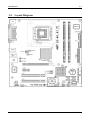
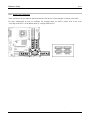
IG-80 Series
Intel Pentium 4 System Board
Socket 775
User’s Manual
4200-0427-02
Rev. 1.01
Copyright and Warranty Notice
The information in this document is subject to change without notice and does not
represent a commitment on part of the vendor, who assumes no liability or
responsibility for any errors that may appear in this manual.
No warranty or representation, either expressed or implied, is made with respect to the
quality, accuracy or fitness for any particular part of this document. In no event shall
the manufacturer be liable for direct, indirect, special, incidental or consequential
damages arising from any defect or error in this manual or product.
Product names appearing in this manual are for identification purpose only and
trademarks and product names or brand names appearing in this document are the
property of their respective owners.
This document contains materials protected under International Copyright Laws. All
rights reserved. No part of this manual may be reproduced, transmitted or transcribed
without the expressed written permission of the manufacturer and authors of this
manual.
If you do not properly set the motherboard settings, causing the motherboard to
malfunction or fail, we cannot guarantee any responsibility.
IG-80 Series
Table Of Contents
Chapter 1.
1-1.
1-2.
Chapter 2.
2-1.
2-2.
2-3.
2-4.
Hardware Setup.................................................................... 2-1
Install The Motherboard...........................................................................2-1
Install CPU, Heatsink and Fan Assembly................................................2-2
Install System Memory ............................................................................2-4
Connectors, Headers and Switches ..........................................................2-5
(1). ATX Power Input Connectors........................................................2-5
(2). FAN Power Connectors .................................................................2-6
(3). CMOS Memory Clearing Header ..................................................2-7
(4). Wake-up Header.............................................................................2-8
(5). Front Panel Audio Connection Header ..........................................2-9
(6). Front Panel Switches & Indicators Headers ................................2-10
(7). Additional IEEE1394 Port Headers (IG-80)................................2-11
(8). Additional USB Port Headers......................................................2-12
(9). System Management Bus Headers...............................................2-13
(10). Internal Audio Connectors ...........................................................2-13
(11). Floppy and IDE Disk Drive Connectors ......................................2-14
(12). Serial ATA Connectors .................................................................2-15
(13). PCI Express x16 Slot ...................................................................2-16
(14). PCI Express x1 Slot .....................................................................2-16
(15). Back Panel Connectors ................................................................2-17
Chapter 3.
3-1.
3-2.
3-3.
3-4.
3-5.
3-6.
3-7.
3-8.
3-9.
3-10.
3-11.
Introduction .......................................................................... 1-1
Features & Specifications ........................................................................1-1
Layout Diagram .......................................................................................1-3
BIOS Setup............................................................................ 3-1
SoftMenu Setup........................................................................................3-2
Standard CMOS Features.........................................................................3-4
Advanced BIOS Features.........................................................................3-7
Advanced Chipset Features....................................................................3-10
Integrated Peripherals ............................................................................3-12
Power Management Setup .....................................................................3-17
PnP/PCI Configurations.........................................................................3-20
PC Health Status ....................................................................................3-22
Load Fail-Safe Defaults .........................................................................3-23
Load Optimized Defaults .......................................................................3-23
Set Password ..........................................................................................3-23
User’s Manual
3-12.
3-13.
Save & Exit Setup ..................................................................................3-23
Exit Without Saving...............................................................................3-23
Chapter 4.
4-1.
Appendix A.
IG-80 Series
Driver Installation ................................................................ 4-1
Setup Items...............................................................................................4-2
How to Get Technical Support ........................................................ A-1
Introduction
1-1
Chapter 1. Introduction
1-1. Features & Specifications
1. CPU
•
•
Supports Intel LGA775 processors with 800MHz FSB
Supports Intel Hyper-Threading Technology
2. Chipset
•
Intel 915G / Intel ICH6
3. Memory
•
•
•
Two 184-pin DIMM sockets
Supports dual channel DDR400 non-ECC un-buffered memory
Supports maximum memory capacity up to 2GB
4. Graphics Port
•
Integrated Intel Graphics Media Accelerator 900 supports DirectX 9
5. PCI-Express
•
•
PCI-Express x1 for next generation of I/O architecture
PCI-Express x16 for next generation of graphics card
6. SATA 150
•
Supports 4 ports Serial ATA 1.5Gbps data transfer rate
7. Audio
•
Onboard 6-channel Audio CODEC
8. IEEE 1394 (IG-80)
•
Supports 2 ports IEEE 1394 at 100/200/400 Mb/s transfer rate
9. Gigabit LAN
•
Onboard Gigabit PCI LAN controller
10. ABIT Engineered
•
ABIT SoftMenu™ Technology
11. Internal I/O Connectors
•
•
•
•
•
•
1x PCI-Express x16 slot
1x PCI-Express x1 slot
2x PCI slots
1x Floppy port supports up to 2.88MB
1x Ultra DMA 100/66/33 IDE connector
4x Serial ATA 1.5Gbps connectors
User’s Manual
1-2
Chapter 1
•
•
•
•
2x USB 2.0 headers
1x IEEE 1394 header (IG-80)
1x FP-Audio header
1x CD-IN header
12. Back Panel I/O
•
•
•
•
•
•
•
1x PS/2 Keyboard, 1x PS/2 mouse
1x Serial port connector, 1x Parallel port connector
1x VGA connector
1x AUDIO connector (Mic-In, Line-In, Line-Out)
4x USB 2.0 connectors
1x IEEE 1394 connector (IG-80)
1x RJ-45 LAN connector
13. Miscellaneous
•
mATX form factor (245mm x 245mm)
14. Order Information
Model
Features
IG-80
GbE LAN, IEEE1394
IG-81
GbE LAN
Specifications and information contained herein are subject to change without notice.
IG-80 Series
Introduction
1-3
1-2. Layout Diagram
User’s Manual
1-4
IG-80 Series
Chapter 1
Hardware Setup
2-1
Chapter 2. Hardware Setup
Before the Installation: Turn off the power supply switch (fully turn off the +5V standby power), or
disconnect the power cord before installing or unplugging any connectors or add-on cards. Failing to do
so may cause the motherboard components or add-on cards to malfunction or damaged.
2-1. Install The Motherboard
Most computer chassis have a base with many mounting holes to allow motherboard to be securely
attached on and at the same time, prevented from short circuits. There are two ways to attach the
motherboard to the chassis base:
1. use with studs
2. or use with spacers
In principle, the best way to attach the board is to
use with studs. Only if you are unable to do this
should you attach the board with spacers. Line up
the holes on the board with the mounting holes on
the chassis. If the holes line up and there are
screw holes, you can attach the board with studs.
If the holes line up and there are only slots, you
can only attach with spacers. Take the tip of the
spacers and insert them into the slots. After doing
this to all the slots, you can slide the board into
position aligned with slots. After the board has been positioned, check to make sure everything is OK
before putting the chassis back on.
ATTENTION: To prevent shorting the PCB circuit, please REMOVE the metal studs or spacers if they
are already fastened on the chassis base and are without mounting-holes on the motherboard to align with.
User’s Manual
2-2
Chapter 2
2-2. Install CPU, Heatsink and Fan Assembly
In order to protect the contact pins, please pay
attention to these notices:
1. A maximum 20 cycles of CPU installation
is recommended.
2. Never touch the contact pins with fingers
or any object.
3. Always put on the cap when the CPU is
not in use.
4. Use your right thumb and forefinger to
grasp the CPU package. Be sure to grasp on the
edge of the substrate, and face the Pin-1
indicator toward the bottom-left side. Aim at the
socket and place the CPU package vertical
down into the socket.
1. Place the board so as to let the lever hook
of the socket is on your left side. Use your left
thumb and forefinger to hold the lever hook,
pull it away from the retention tab.
5. Visually inspect if the CPU is seated well
into the socket. The alignment key must be
located in the notch of package.
2.
Rotate the lever to fully open position.
6. Use your left hand to hold the load plate,
and use your right thumb to peel the cap off.
3. Use your right thumb on the bottom-right
side of the load plate and lift it up to fully open
position.
IG-80 Series
Hardware Setup
The cap plays an important role in protecting
contact pins. In order to prevent bent pin, PUT
ON the cap after operation or testing.
2-3
For detailed information on how to install your
heatsink and fan assembly, please refer to the
instruction manual came packed with the
heatsink and fan assembly you bought.
7. Lower the plate onto the CPU package.
Engage the load lever while gently pressing
down the load plate.
10. Press each of the four fasteners down into
the mounting holes.
8. Secure the lever with the hook under
retention tab.
11. Rotate the fastener clock-wise to lock the
heatsink and fan assembly into position.
9. Place the heatsink and fan assembly onto
the socket. Align the four fasteners toward the
four mounting holes on the motherboard.
12. Attach the four-pin power plug from the
heatsink and fan assembly to the CPU FAN
connector.
User’s Manual
2-4
Chapter 2
2-3. Install System Memory
This system board provides two 184-pin DDR DIMM slots for DDR 400/333 memory modules with
memory expansion size up to 2GB.
Bank
Memory Module
Total Memory
Bank 0, 1 (DIMM1)
256MB, 512MB, 1GB
256MB ~ 1GB
Bank 2, 3 (DIMM2)
256MB, 512MB, 1GB
256MB ~ 1GB
Total System Memory
256MB ~ 2GB
NOTE: Usually there is no hardware or BIOS setup require after adding or removing memory modules,
but you will have to clear the CMOS memory first if any memory module related problem occurs.
Power off the computer and unplug the AC power cord before installing or removing memory modules.
1.
Locate the DIMM slot on the board.
2.
Hold two edges of the DIMM module
carefully, keep away of touching its
connectors.
3.
Align the notch key on the module with the
rib on the slot.
4.
Firmly press the module into the slots until
the ejector tabs at both sides of the slot
automatically snaps into the mounting notch. Do not force the DIMM module in with extra force as
the DIMM module only fit in one direction.
5.
To remove the DIMM modules, push the two ejector tabs on the slot outward simultaneously, and
then pull out the DIMM module.
ATTENTION: Static electricity can damage the electronic components of the computer or optional
boards. Before starting these procedures, ensure that you are discharged of static electricity by touching a
grounded metal object briefly.
IG-80 Series
Hardware Setup
2-5
2-4. Connectors, Headers and Switches
Here we will show you all of the connectors, headers and switches, and how to connect them. Please read
the entire section for necessary information before attempting to finish all the hardware installation inside
the computer chassis. A complete enlarged layout diagram is shown in Chapter 1 for all the position of
connectors and headers on the board that you may refer to.
WARNING: Always power off the computer and unplug the AC power cord before adding or removing
any peripheral or component. Failing to so may cause severe damage to your motherboard and/or
peripherals. Plug in the AC power cord only after you have carefully checked everything.
(1).
ATX Power Input Connectors
This motherboard provides two power connectors to connect ATX12V power supplier.
NOTE: This 24-pin power connector “ATXPWR1” is compliant to the former 20-pin type. Pay attention
to the orientation when doing so (Pin-11, 12, 23, and 24 should be left un-connected).
User’s Manual
2-6
(2).
Chapter 2
FAN Power Connectors
These connectors each provide power to the cooling fans installed in your system.
•
CPUFAN1: CPU Fan Power Connector
•
NBFAN1: Chipset Fan Power Connector
•
SYSFAN1: System Fan Power Connector
•
AUXFAN1, AUXFAN2: Auxiliary Fan Power Connector
WARNING: These fan connectors are not jumpers. DO NOT place jumper caps on these connectors.
IG-80 Series
Hardware Setup
(3).
2-7
CMOS Memory Clearing Header
This header uses a jumper cap to clear the CMOS memory.
•
Pin 1-2 shorted (default): Normal operation.
•
Pin 2-3 shorted: Clear CMOS memory.
WARNING: Turn the power off first (including the +5V standby power) before clearing the CMOS
memory. Failing to do so may cause your system to work abnormally or malfunction.
User’s Manual
2-8
(4).
Chapter 2
Wake-up Header
These headers use a jumper cap to enable/disable the wake-up function.
•
USB-PWR1:
Pin 1-2 shorted (default): Disable wake-up function support at USB1 port.
Pin 2-3 shorted: Enable wake-up function support at USB1 port.
•
USB-PWR2:
Pin 1-2 shorted (default): Disable wake-up function support at USB2 port.
Pin 2-3 shorted: Enable wake-up function support at USB2 port
IG-80 Series
Hardware Setup
(5).
2-9
Front Panel Audio Connection Header
This header provides the connection to audio connector at front panel.
•
To use the audio connector at front panel, remove all the jumpers on this header, and then connect
to front panel by the extension cable provided with the chassis.
•
To use the audio connector at rear panel, disconnect the extension cable, attach the jumpers back at
pin 5-6, and pin 9-10 (default setting).
Pin
1
3
5
7
9
Pin Assignment
Audio Mic.
Audio Mic. Bias
Speaker Out Right
Channel
X
Speaker Out Left
Channel
Pin
2
4
6
8
10
Pin Assignment
Ground
VCC
Speaker Out Right
Channel Return
NC
Speaker Out Left
Channel Return
User’s Manual
2-10
(6).
Chapter 2
Front Panel Switches & Indicators Headers
This header is used for connecting switches and LED indicators on the chassis front panel.
Watch the power LED pin position and orientation. The mark “+” align to the pin in the figure below
stands for positive polarity for the LED connection. Please pay attention to connect these headers. A
wrong orientation will only cause the LED not lighting, but a wrong connection of the switches could
cause system malfunction.
•
HLED (Pin 1, 3):
Connects to the HDD LED cable of chassis front panel.
•
RST (Pin 5, 7):
Connects to the Reset Switch cable of chassis front panel.
•
SPK (Pin 15, 17, 19, 21):
Connects to the System Speaker cable of chassis.
•
SLED (Pin 2, 4):
Connects to the Suspend LED cable (if there is one) of chassis front panel.
•
PWR-ON (Pin 6, 8):
Connects to the Power Switch cable of chassis front panel.
•
PLED (Pin 16, 18, 20):
Connects to the Power LED cable of chassis front panel.
IG-80 Series
Hardware Setup
2-11
(7). Additional IEEE1394 Port Headers (IG-80)
These headers each provide one additional IEEE1394 port connection through an extension cable and
bracket.
Pin
Pin Assignment
Pin
Pin Assignment
1
TPA0 +
2
TPA0 -
3
Ground
4
Ground
5
TPB0 +
6
TPB0 -
7
+12V
8
+12V
9
NC
10
Ground
User’s Manual
2-12
(8).
Chapter 2
Additional USB Port Headers
These headers each provide 2 additional USB 2.0 ports connection through an USB cable designed for
USB 2.0 specifications.
Pin
IG-80 Series
Pin Assignment
Pin
Pin Assignment
1
VCC
2
VCC
3
Data0 -
4
Data1 -
5
Data0 +
6
Data1 +
7
Ground
8
Ground
9
NC
10
NC
Hardware Setup
(9).
2-13
System Management Bus Headers
This header is reserved for system management bus (SM bus). The SM bus is a specific implementation
of an I2C bus. I2C is a multi-master bus, which means that multiple chips can be connected to the same
bus and each one can act as a master by initiating a data transfer. If more than one master simultaneously
tries to control the bus, an arbitration procedure decides which master gets priority.
(10). Internal Audio Connectors
These connectors connect to the audio output of internal CD-ROM drive or add-on card.
User’s Manual
2-14
Chapter 2
(11). Floppy and IDE Disk Drive Connectors
The FDC1 connector connects up to two floppy drives with a 34-wire, 2-connector floppy cable. Connect
the single end at the longer length of ribbon cable to the FDC1 on the board, the two connectors on the
other end to the floppy disk drives connector. Generally you need only one floppy disk drive in your
system.
NOTE: The red line on the ribbon cable must be aligned with pin-1 on both the FDC1 port and the floppy
connector.
Each of the IDE port connects up to two IDE drives at
Ultra ATA/100 mode by one 40-pin, 80-conductor, and
3-connector Ultra ATA/66 ribbon cables.
Connect the single end (blue connector) at the longer
length of ribbon cable to the IDE port of this board, the
other two ends (gray and black connector) at the shorter
length of the ribbon cable to the connectors of your hard
drives.
NOTE: Make sure to configure the “Master” and “Slave” relation before connecting two drives by one
single ribbon cable. The red line on the ribbon cable must be aligned with pin-1 on both the IDE port and
the hard-drive connector.
IG-80 Series
Hardware Setup
2-15
(12). Serial ATA Connectors
These connectors are provided to attach one Serial ATA device at each channel via Serial ATA cable.
For more information on how to configure the function mode for SATA, please refer to the item
“On-Chip Serial ATA” in the BIOS menu of “OnChip IDE Device”.
User’s Manual
2-16
(13). PCI Express x16 Slot
This slot is used to attach the next generation of graphics architecture.
(14). PCI Express x1 Slot
This slot is used to attach the next generation of I/O architecture.
IG-80 Series
Chapter 2
Hardware Setup
2-17
(15). Back Panel Connectors
•
Mouse: Connects to PS/2 mouse.
•
Keyboard: Connects to PS/2 keyboard.
•
LPT1: Connects to printer or other devices that support this communication protocol.
•
COM1: Connects to external modem, mouse or other devices that support this communication
protocol.
•
VGA1: Connects to monitor input.
• AUDIO2:
Mic-In: Connects to the plug from external microphone.
Line-In: Connects to the line out from external audio sources.
Line-Out: Connects to the front left and front right channel in the 5.1-channel or regular 2-channel
audio system.
•
IEEE1394: Connects to devices of IEEE1394 protocol. (IG-80)
•
LAN: Connects to Local Area Network.
•
USB1/USB2: Connects to USB devices such as scanner, digital speakers, monitor, mouse,
keyboard, hub, digital camera, joystick, etc.
User’s Manual
2-18
IG-80 Series
Chapter 2
BIOS Setup
3-1
Chapter 3. BIOS Setup
This motherboard provides a programmable EEPROM that you can update the BIOS utility. The BIOS
(Basic Input/Output System) is a program that deals with the basic level of communication between
processor and peripherals. Use the BIOS Setup program only when installing motherboard, reconfiguring
system, or prompted to “Run Setup”. This chapter explains the Setup Utility of BIOS utility.
After powering up the system, the BIOS message appears on the screen, the memory count begins, and
then the following message appears on the screen:
PRESS DEL TO ENTER SETUP
If this message disappears before you respond, restart the system by pressing <Ctrl> + <Alt> + <Del>
keys, or by pressing the Reset button on computer chassis. Only when it failed by these two methods can
you restart the system by powering it off and then back on.
After pressing <Del> key, the main menu screen appears.
NOTE: In order to increase system stability and performance, our engineering staffs are constantly
improving the BIOS menu. The BIOS setup screens and descriptions illustrated in this manual are for
your reference only, and may not completely match with what you see on your screen.
User’s Manual
3-2
Chapter 3
3-1. SoftMenu Setup
The SoftMenu utility is ABIT’s exclusive and ultimate solution in programming the CPU operating speed.
All the parameters regarding CPU FSB speed, multiplier factor, the AGP & PCI clock, and even the CPU
core voltage are all available at your fingertips.
Brand Name:
This item displays the CPU model name, for example: Intel Pentium (R) 4.
Frequency:
This item displays the processor speed.
Cache Size:
This item displays the L2 cache size of your CPU.
CPU Operating Speed:
This item displays the CPU operating speed according to the type and speed of your CPU. You can also
select the [User Define] option to enter the manual option.
User Define:
WARNING: The wrong settings of the multiplier and external clock in certain circumstances may cause
CPU damage. Setting the working frequency higher than the PCI chipset or processor specs, may cause
abnormal memory module functioning, system hangs, hard disk drive data lose, abnormal functioning of
the VGA card, or abnormal functioning with other add-on cards. Using non-specification settings for your
CPU is not the intention of this explanation. These should be used for engineering testing, not for normal
applications.
There will be no guaranty for the settings beyond specification, any damage of any component on this
motherboard or peripherals result therein is not our responsibility.
External Clock:
This item selects the external clock frequency.
IG-80 Series
BIOS Setup
3-3
Multiplier Factor:
This item selects the multiplier factors for your CPU if it is not locked.
Estimated new CPU Clock:
This item displays the frequency sum up from the previous item [External Clock] and [Multiplier Factor].
N/B Strap CPU As:
This item sets the external hardware reset strap assigned to MCH (Memory Controller Hub). The options
are: [PSB533], [PSB800], and [By CPU]. The default setting is By CPU.
To set this option manually:
• Select [PSB533] for CPU of 133MHz FSB frequency.
• Select [PSB800] for CPU of 200MHz FSB frequency.
DRAM Ratio (CPU:DRAM):
This item determines the frequency ratio between CPU and DRAM.
PCI Express Frequency:
This item determines the frequency for PCI Express.
Fixed PCI Frequency:
This item determines the PCI bus frequency. This option allows you to keep your PCI clock at some fixed
frequency to improve system stability.
Voltage Control:
This item selects the voltage supplied to your system.
To adjust the following items manually, select the “Manual” option.
CPU Core Voltage:
This item selects the CPU core voltage.
ATTENTION: A wrong voltage setting may cause the system unstable or even damage the CPU. Please
leave it to default settings unless you are fully aware of its consequences.
DDR SDRAM Voltage:
This item selects the voltage supplied to memory slots.
NB Voltage:
This item selects the voltage supplied to North Bridge.
User’s Manual
3-4
Chapter 3
3-2. Standard CMOS Features
This section contains the basic configuration parameters of the BIOS. These parameters include date,
hour, VGA card, FDD, and HDD settings.
Date (mm:dd:yy):
This item sets the date you specify (usually the current date) in the format of [Month], [Date], and [Year].
Time (hh:mm:ss):
This item sets the time you specify (usually the current time) in the format of [Hour], [Minute], and
[Second].
IDE Channel 1 Master/Slave, IDE Channel 2 Master/Slave, IDE Channel 3
Master/Slave, IDE Channel 4 Master/Slave:
Click <Enter> key to enter its submenu:
NOTE: The items “IDE Channel 3 Master/Slave” and “IDE Channel 4 Master/Slave” appear only when
the item “On-Chip Serial ATA” in the “OnChip IDE Device” menu is set to [Enhanced Mode], or set to
[Auto Mode] when SATA ports are connected with devices.
IG-80 Series
BIOS Setup
3-5
IDE HDD Auto-Detection:
This item allows you to detect the parameters of IDE drives by pressing <Enter> key. The parameters will
be shown on the screen automatically.
IDE Channel 1 Master/Slave, IDE Channel 2 Master/Slave, Extended IDE Drive:
When set to [Auto], the BIOS will automatically check what kind of IDE drive you are using. If you want
to define your own drive by yourself, set it to [Manual] and make sure you fully understand the meaning
of the parameters. Please refer to the instruction manual provided by the device’s manufacturer to get the
setting right.
Access Mode:
This item selects the mode to access your IDE devices. Leave this item to its default [Auto] setting to
detect the access mode of your HDD automatically.
Capacity:
This item displays the approximate capacity of the disk drive. Usually the size is slightly greater than the
size of a formatted disk given by a disk-checking program.
Cylinder:
This item configures the numbers of cylinders.
Head:
This item configures the numbers of read/write heads.
Precomp:
This item displays the number of cylinders at which to change the write timing.
Landing Zone:
This item displays the number of cylinders specified as the landing zone for the read/write heads.
Sector:
This item configures the numbers of sectors per track.
Back to Standard CMOS Features Setup Menu:
Drive A & Drive B:
This item sets the type of floppy drives (usually only Drive A) installed.
Floppy 3 Mode Support:
This item allows you to use “3 Mode Floppy Drive” in Japanese computer system by selecting drive A, B,
or both. Leave this item to its default [Disabled] setting if you are not using this Japanese standard floppy
drive.
Halt On:
This item determines whether the system stops if an error is detected during system boot-up.
User’s Manual
3-6
Chapter 3
[All Errors]: The system-boot will stop whenever the BIOS detect a non-fatal error.
[No Errors]: The system-boot will not stop for any error detected.
[All, But Keyboard]: The system-boot will stop for all errors except a keyboard error.
[All, But Diskette]: The system-boot will stop for all errors except a diskette error.
[All, But Disk/Key]: The system-boot will stop for all errors except a diskette or keyboard error.
Base Memory:
This item displays the amount of base memory installed in the system. The value of the base memory is
typically 640K for system with 640K or more memory size installed on the motherboard.
Extended Memory:
This item displays the amount of extended memory detected during system boot-up.
Total Memory:
This item displays the total memory available in the system.
IG-80 Series
BIOS Setup
3-7
3-3. Advanced BIOS Features
CPU L3 Cache:
This item is used to enable the L3 cache (default setting), and appears only for certain CPU (Intel Pentium
4 processor with HT Technology Extreme Edition) that possesses L3 cache.
Hyper-Threading Technology
This item is used to enable the functionality of the processor with Hyper-Threading Technology and will
appear only when using such processor.
The Hyper-Threading Technology helps your PC work more efficiently by maximizing processor
resources and enabling a single processor to run two separate threads of software simultaneously,
bringing forth greater performance and system responsiveness when running multiple applications at
once.
Quick Power On Self Test:
When set to [Enabled], this item speeds up the Power On Self Test (POST) after powering on the system.
The BIOS shorten or skip some check during the POST.
CPU Feature:
Click <Enter> key to enter its submenu:
User’s Manual
3-8
Chapter 3
Delay Prior to Thermal:
This item selects the delay time before thermal activation.
Thermal Management
This item selects the type of thermal monitoring.
Limit CPUID MaxVal
When set to [Enabled], this item limits the CPUID maximum value to 3, which is usually required for
older OS like Windows NT4.0.
Leave this item to its default [Disabled] settings for OS like Windows XP.
Back to Advanced BIOS Features Setup Menu:
Hard Disk Boot Priority:
This item selects the hard disks booting priority. By pressing <Enter> key, you can enter its submenu
where the hard disks detected can be selected for the booting sequence to boot up system.
This item functions only when there is the option of [Hard Disk] in any one of the First/Second/Third
Boot Device items.
First Boot Device / Second Boot Device / Third Boot Device / Boot Other Device:
Select the drive to boot first, second and third in the [First Boot Device], [Second Boot Device], and
[Third Boot Device] items respectively. The BIOS will boot the operating system according to the
sequence of the drive selected. Set [Boot Other Device] to [Enabled] if you wish to boot from another
device other than these three items.
Swap Floppy Drive:
When set to [Enabled], and the system is booting from the floppy drive, the system will boot from drive B
instead of the regular drive A. There must be two floppy drives connected in the system to use this
function.
Boot Up Floppy Seek:
When set to [Enabled], the BIOS will check whether the floppy disk drive is installed or not.
Boot Up NumLock Status:
This item determines the default state of the numeric keypad at system booting up.
[On]: The numeric keypad functions as number keys.
[Off]: The numeric keypad functions as arrow keys.
Security Option:
This item determines when the system will prompt for password - every time the system boots or only
when enters the BIOS setup.
[Setup]: The password is required only when accessing the BIOS Setup.
[System]: The password is required each time the computer boots up.
IG-80 Series
BIOS Setup
3-9
NOTE: Don’t forget your password. If you forget the password, you will have to open the computer case
and clear all information in the CMOS before you can start up the system. But by doing this, you will
have to reset all previously set options.
MPS Version Ctrl For OS:
This item specifies which version of MPS (Multi-Processor Specification) this motherboard will use.
Leave this item to its default setting.
OS Select For DRAM > 64MB
This item allows you to access the memory that is over 64MB in OS/2. Leave this item to its default
[Non-OS2] setting for operating system other than OS/2.
Report No FDD For OS:
When set to [Yes], this item allows you to run some older operating system without floppy disk drive.
Leave this item to its default setting.
Delay IDE Initial (Secs):
This item allows the BIOS to support some old or special IDE devices by prolonging this delay time. A
larger value will give more delay time to the device for which to initialize and to prepare for activation.
Intel OnScreen Branding:
This item determines whether to display the “Intel Inside” logo or not at system boots up.
Disable Unused PCI Clock:
This option disables the clock of PCI slot that is not in use.
[Yes]: The system automatically detect the unused DIMM and PCI slots, and stop sending clock signal to
these unused PCI slots.
[No]: The system always send clock signal to all PCI slots.
NOTE: Set this option to [No] setting if there are adapters that cannot be automatically detected by the
system and will cause malfunction.
User’s Manual
3-10
Chapter 3
3-4. Advanced Chipset Features
DRAM Timing Selectable:
This item sets the optimal timings for the following four items, depending on the memory module you are
using. The default setting “By SPD” configures these four items by reading the contents in the SPD
(Serial Presence Detect) device. The EEPROM on the memory module stores critical parameter
information about the module, such as memory type, size, speed, voltage interface, and module banks.
CAS Latency Time:
This item controls the latency between the DRAM read command and the time that the data becomes
actually available.
DRAM RAS# to CAS# Delay
This item controls the latency between the DRAM active command and the read/write command.
DRAM RAS# Precharge:
This item controls the idle clocks after issuing a precharge command to the DRAM.
Precharge Delay (tRAS):
This item controls the number of DRAM clocks used for the DRAM parameters.
Memory Hole At 15M-16M:
When set to [Enabled], the memory address space at 15M-16M will be reserved for ISA expansion cards
that specifically requires this setting. This makes the memory from 15MB and up unavailable to the
system. Leave this item to its default setting.
IG-80 Series
BIOS Setup
3-11
PCI Express Root Port Func:
Click <Enter> key to enter its submenu:
PCI Express Slot 1:
This option enables or disables the PCI Express port function.
PCI-E Compliancy Mode:
This item selects the mode for PCI Express add-on card.
Back to Advanced Chipset Features Setup Menu:
Init Display First:
This item selects whether to initiates from “PCI Slot”, “Onboard”, or “PCIEX” first when system boots
up.
PEG/Onchip VGA Control:
This item selects which one to initiates from “Onchip VGA” or “PEG Port” when system boots up.
Leave this item to its default [Auto] settings.
PEG Force X1:
When set to [Enabled], this item forces the PEG port down to x1 mode.
On-Chip Video Memory Size:
This option specifies the amount of system memory that can be used by the AGP device. The aperture is a
portion of the PCI memory address range dedicated for graphics memory address space.
User’s Manual
3-12
Chapter 3
3-5. Integrated Peripherals
OnChip IDE Device:
Click <Enter> key to enter its submenu:
IDE Bus Master:
This option enables or disables the IDE bus mastering capability under the DOS environment.
On-Chip IDE-1 Controller:
This item selects whether to enable or disable the IDE-1 controller.
On-Chip Serial ATA:
This item determines the function for on-chip Serial ATA.
[Disabled]: Disable the Serial ATA controller.
[Auto]: Allows the Serial ATA controller to be arranged by BIOS automatically.
[Combined Mode]: Parallel ATA and Serial ATA are combined together. Supports up to 4 IDE drives.
[Enhanced Mode]: Enable both Parallel ATA and Serial ATA. Supports up to 6 IDE drives.
[SATA Only]: The SATA is operating in legacy mode.
IG-80 Series
BIOS Setup
3-13
IDE
IDE
IDE
IDE
IDE
IDE
IDE
IDE
Channel Channel Channel Channel Channel Channel Channel Channel
1 Master 1 Slave 2 Master 2 Slave 3 Master 3 Slave 4 Master 4 Slave
IDE1
IDE1
Enhanced
None
None
SATA1
SATA3
SATA2
SATA4
Master
Slave
IDE1
IDE1
Combined
SATA2
SATA4
None
None
None
None
Master
Slave
SATA Only SATA1 SATA3
SATA2
SATA4
None
None
None
None
Mode
NOTE: The option [Enhanced Mode] does not support the Windows 98/ME operation system.
Parallel ATA Mode:
This item determines the function mode for “IDE1”connector.
[IDE1]: “IDE1” connector served as [Primary Master] and [Primary Slave] channel. “SATA2” and
“SATA4”connector served as [Secondary Master] and [Secondary Slave] channel. The remaining
“SATA1” and “SATA3” connectors are disabled.
[IDE2]: “IDE1” connector served as [Secondary Master] and [Secondary Slave] channel. “SATA1” and
“SATA3” connector served as [Primary Master] and [Primary Slave] channel. The remaining “SATA2”
and “SATA4” connectors are disabled.
Refer to the following table for the relationships between IDE and SATA ports.
PATA IDE
Mode
Primary
Secondary
IDE
IDE
IDE
IDE
IDE
IDE
IDE
IDE
Channel Channel Channel Channel Channel Channel Channel Channel
1 Master 1 Slave 2 Master 2 Slave 3 Master 3 Slave 4 Master 4 Slave
IDE1
IDE1
SATA2
SATA4
None
None
None
None
Master
Slave
IDE1
IDE1
SATA1 SATA3
None
None
None
None
Master
Slave
NOTE: This option is configurable only when the item [On-Chip Serial ATA] is set to [Combined
Mode].
Serial ATA Mode:
This item displays the variety modes for SATA Ports.
User’s Manual
3-14
Chapter 3
OnChip PCI Device:
Click <Enter> key to enter its submenu:
OnChip USB Controller:
This option enables or disables the USB controller.
USB 2.0 Controller:
This option enables or disables the USB 2.0 controller.
USB Keyboard Support Via:
This item allows you to select [BIOS] for using USB keyboard in DOS environment, or [OS] in OS
environment.
USB Mouse Support Via:
This item allows you to select [BIOS] for using USB mouse in DOS environment, or [OS] in OS
environment.
OnChip Audio Controller:
This option enables or disables the audio controller.
SuperIO Device:
Click <Enter> key to enter its submenu:
IG-80 Series
BIOS Setup
3-15
Onboard FDD Controller:
This option enables or disables the onboard FDC controller.
Onboard Serial Port:
This item determines which I/O addresses the onboard Serial Port controller will access.
[Auto]: The system automatically select an I/O address for the onboard Serial Port.
[3F8/IRQ4, 2F8/IRQ3, 3E8/IRQ4, 2E8/IRQ3]: Allows you to manually select an I/O address for the
onboard Serial Port.
[Disabled]: Disables the onboard Serial Port.
Onboard Parallel Port:
This item specifies the I/O address used by the parallel port.
[Disabled]: This option prevents the parallel port from accessing any system resources. When the value
of this option is set to [Disabled], the printer port becomes unavailable.
[378/IRQ7]: This option allows the parallel port to use [378/IRQ7] as its I/O port address. The majority
of parallel ports on computer systems use IRQ7 and I/O Port 378H as the standard setting.
[278/IRQ5]: This option allows the parallel port to use [278/IRQ5] as its I/O port address.
[3BC/IRQ7]: This option allows the parallel port to use [3BC/IRQ7] as its I/O port address.
Parallel Port Mode:
This item specifies the parallel port mode.
[SPP]: (Standard Parallel Port) Allows bi-directional parallel port operation at normal speed.
[EPP]: (Enhanced Parallel Port) Allows bi-directional parallel port operation at maximum speed.
[ECP]: (Extended Capabilities Port) Allows bi-directional parallel port operation at a speed faster than
the normal mode’s data transfer rate.
[ECP+EPP]: Allows parallel port operation at ECP and EPP mode.
ECP Mode Use DMA:
This item selects the DMA channel of the parallel port.
User’s Manual
3-16
Chapter 3
Onboard PCI Device:
Click <Enter> key to enter its submenu:
IEEE 1394 Controller: (IG-80)
This option enables or disables the IEEE 1394 controller.
Network Controller:
This option enables or disables the LAN controller.
Invoke Boot Agent:
This item allows you to use the boot ROM (instead of a disk drive) to boot-up the system and access the
local area network directly.
IG-80 Series
BIOS Setup
3-17
3-6. Power Management Setup
ACPI Suspend Type:
This item selects the type of Suspend mode.
[S1(PowerOn-Suspend)]: Enables the Power On Suspend function.
[S3(Suspend-To-RAM)]: Enables the Suspend to RAM function.
Resume by USB From S3:
When set to [Enabled], this item allows you to use a USB device to wake up a system that is in the S3
(STR - Suspend To RAM) state. This item can be configured only if the item “ACPI Suspend Type” is set
to [S3(STR)].
Power Button Function:
This item selects the method of powering off your system:
[Delay 4 Sec.]: Pushing the power button for more than 4 seconds will power off the system. This will
prevent the system from powering off in case you accidentally hit or pushed the power button.
[Instant-Off]: Pressing and then releasing the power button at once will immediately power off the
system.
CPU THRM-Throttling
This item controls the CPU speed by cutting down its regular power to a percentage during the STR
(Suspend To RAM) state.
WakeUp by PME# of PCI:
When set to [Enabled], access to the onboard LAN or a PCI card such as a modem or LAN card will
cause the system to wake up. The PCI card must support the wake up function.
WakeUp by Ring:
When set to Enabled, any event affecting from Modem Ring will awaken a system that has been powered
down.
User’s Manual
3-18
Chapter 3
WakeUp by Onboard LAN:
When set to [Enabled], you can remotely wake up a PC in Soft-Off condition via a LAN card that support
the wake up function.
WakeUp by Alarm:
When set to [Enabled], you can set the date and time you would like the Soft-Off PC to power-on in the
“Date (of Month) Alarm” and “Time (hh:mm:ss) Alarm” items. However, if the system is being
accessed by incoming calls or the network (Resume On Ring/LAN) prior to the date and time set in these
items, the system will give priority to the incoming calls or network instead.
Date (of Month) Alarm
[0]: This option power-on the system everyday according to the time set in the “Time (hh:mm:ss) Alarm”
item.
[1-31]: This option selects a date you would like the system to power-on. The system will power-on on
the date set, and the time set in the “Time (hh:mm:ss) Alarm” item.
Time (hh:mm:ss) Alarm
This item sets the time you would like the system to power-on.
POWER ON Function:
This item selects the way you want your system to power on.
[Password]: Use a password to power on the system, select this option then press <Enter>. Enter your
password. You can enter up to 5 characters. Type in exactly the same password to confirm, and then press
<Enter>.
[Hot KEY]: Use any of the function keys between <F1> to <F12> to power on the system.
[Mouse Left]: Double click the mouse left button to power on the system.
[Mouse Right]: Double click the mouse right button to power on the system.
[Any KEY]: Use any keyboard keys to power on the system.
[Button Only]: Use only the power button to power on the system.
[Keyboard 98]: Use the power-on button on the “Keyboard 98” compatible keyboard to power on the
system.
NOTE: To enable this “Power On” function, the wake-up header of [USB-PWR1], [USB-PWR2] must
be set to [Enabled] position. Please refer to the configuration of “Wake-up Header” [USB-PWR1], and
[USB-PWR2] in section 2-4, chapter 2.
NOTE: The mouse wake up function can only be used with the PS/2 mouse, not with the COM port or
USB type. Some PS/2 mice cannot wake up the system because of compatible problems. If the specs of
your keyboard are too old, it may fail to power on.
KB Power ON Password:
This item sets the password required in order to power on your computer.
NOTE: Do not forget your password, or you will have to clear the CMOS and reset all parameters in
order to utilize this function again.
IG-80 Series
BIOS Setup
3-19
Hot Key Power ON:
This item powers on the system by pressing <Ctrl> key plus one of each function key (<F1> ~ <F12>)
simultaneously.
Restore On AC Power Loss:
This item selects the system action after an AC power failure.
[Power Off]: When power returns after an AC power failure, the system’s power remains off. You must
press the Power button to power-on the system.
[Power On]: When power returns after an AC power failure, the system’s power will be powered on
automatically.
[Last State]: When power returns after an AC power failure, the system will return to the state where you
left off before power failure occurs. If the system’s power is off when AC power failure occurs, it will
remain off when power returns. If the system’s power is on when AC power failure occurs, the system
will power-on when power returns.
User’s Manual
3-20
Chapter 3
3-7. PnP/PCI Configurations
Resources Controlled By:
This item configures all of the boot and Plug-and-Play compatible devices.
[Auto]: The system will automatically detect the settings.
[Manual]: Choose the specific IRQ resources in the “IRQ Resources” menu.
IRQ Resources:
Click <Enter> key to enter its submenu:
This item sets each system interrupt to either [PCI Device] or [Reserved].
PCI/VGA Palette Snoop:
This item determines whether the MPEG ISA/VESA VGA cards can work with PCI/VGA or not.
[Enabled]: MPEG ISA/VESA VGA cards work with PCI/VGA.
[Disabled]: MPEG ISA/VESA VGA cards do not work with PCI/VGA.
Allocate IRQ To Video:
This item assigns an IRQ for the VGA card installed.
IG-80 Series
BIOS Setup
3-21
[Enabled]: Automatically assign an IRQ for the VGA card installed.
[Disabled]: The IRQ that was previously occupied by the VGA card will be available for new device.
Allocate IRQ To USB:
This item assigns an IRQ for the USB device connected.
[Enabled]: Automatically assign an IRQ for the USB device connected.
[Disabled]: The IRQ that was previously occupied by the USB device connected will be available for
new device.
PCI Latency Timer(CLK):
This item controls how long each PCI device can hold the bus before another takes over. When set to
higher values, every PCI device can conduct transactions for a longer time and thus improve the effective
PCI bandwidth. For better PCI performance, you should set the item to higher values.
PIRQ_0 Use IRQ No. ~ PIRQ_7 Use IRQ No.:
This item specifies the IRQ number manually or automatically for the devices installed on PCI slots.
For the relations between the hardware layout of PIRQ (the signals from the ICH chipset), INT# (means
PCI slot IRQ signals) and devices, please refer to the table below:
Signals
PCI
EXP1
LAN
PCI-E1
PIRQ_0 Assignment
INT A
INT A
INT D
INT D
INT B
INT A
INT A
PIRQ_2 Assignment
INT C
INT B
INT B
PIRQ_3 Assignment
INT D
INT C
PIRQ_1 Assignment
PCI-1
PCI-2
IEEE1394
INT C
PIRQ_4 Assignment
INT D
INT C
PIRQ_5 Assignment
INT A
INT B
PIRQ_6 Assignment
INT B
INT A
PIRQ_7 Assignment
INT C
INT D
Maximum Payload Size:
This item sets the maximum TLP payload size for the PCI Express devices.
User’s Manual
3-22
Chapter 3
3-8. PC Health Status
FAN Fail Alarm Selectable:
This item selects the fan that will be monitored for malfunction.
Shutdown When CPUFAN Fail:
When set to [Enabled], the system will be shut down if the CPU fan is not running.
CPU FanEQ Speed Control:
This item allows you to control the CPU fan speed down to a specific percentage.
When set to a specific percentage, the CPU fan speed will run at the percentage you set in this item if the
temperature limit set in the item “Active Temperature” is not exceeded.
The CPU fan speed will run at 100% regardless of what the percentage you set in this item if the
temperature limit set in the item “Active Temperature” is exceeded.
Active Temperature:
This item sets the temperature limit that would activate the function of “CPU FanEQ Speed Control”
option.
CPU Shutdown Temperature:
This item sets the temperature that would shutdown the system automatically in order to prevent system
overheats.
CPU Warning Temperature:
This item selects the CPU’s warning temperature limit. Once the system has detected that the CPU’s
temperature exceeded the limit, warning beeps will sound.
NOTE: The onboard hardware monitor function is capable of detecting these system health conditions. If
you want a warning message to pop-up or a warning alarm to sound when an abnormal condition occurs,
you must install the “Hardware Doctor” utility. This utility is included in the “Driver & Utility CD” that
came packed with this motherboard.
IG-80 Series
BIOS Setup
3-23
All Voltages, Fans Speed and Thermal Monitoring:
These unchangeable items list the current status of the CPU and environment temperatures, fan speeds,
and system power voltage.
NOTE: The hardware monitoring features for temperatures, fans and voltages will occupy the I/O
address from 294H to 297H. If you have a network adapter, sound card or other add-on cards that might
use those I/O addresses, please adjust your add-on card I/O address to avoid using these addresses.
3-9. Load Fail-Safe Defaults
This option loads the BIOS default values for the most stable, minimal-performance system operations.
3-10. Load Optimized Defaults
This option loads the BIOS default values that are factory settings for optimal-performance system
operations.
3-11. Set Password
This option protects the BIOS configuration or restricts access to the computer itself.
3-12. Save & Exit Setup
This option saves your selections and exits the BIOS setup menu.
3-13. Exit Without Saving
This option exits the BIOS setup menu without saving any change.
User’s Manual
3-24
IG-80 Series
Chapter 3
Driver Installation
4-1
Chapter 4. Driver Installation
All the necessary drivers are included within the Drivers & Utilities CD that came packed with the
motherboard. The display shown in the following figure should appear after inserting the Drivers &
Utilities CD into your CD-ROM drive, if not, enter [My Computer] [CD-ROM] Drive double
click [autorun.exe]. Please follow the on-screen instruction.
User’s Manual
4-2
Chapter 4
4-1. Setup Items
•
Intel Chipset Software Utility
Install the Intel Chipset Software Utility for Windows Operating System.
•
Audio Driver
Install the onboard audio driver for Windows Operating System.
•
VGA Driver
Install the onboard VGA driver for Windows Operating System.
•
LAN Driver
Install the onboard LAN driver for Windows Operating System.
•
USB 2.0 Driver
Update the USB 2.0 driver for Windows 2000/XP Operating System via the Windows Updating
Program.
•
Manual
View the user’s manual in PDF file.
•
Utility
Click to enter the sub-screen for installing software like Acrobat Reader, DirectX, and
LoFormat utility.
•
ABIT Utility
Click to enter the sub-screen to install utilities like Flash Menu (BIOS Update Utility) and
Hardware Doctor.
•
Browse CD
Browse the contents of this CD-ROM.
•
Close
Exit the CD setup Items Menu.
IG-80 Series
How to Get Technical Support
A-1
Appendix A. How to Get Technical Support
(From our website) http://www.abit.com.tw
(In North America) http://www.abit-usa.com
(In Europe) http://www.abit.nl
Thank you for choosing ABIT products. ABIT sells all our products through distributors,
resellers and system integrators; we have no direct sales to end-users. Before sending email
for tech support please check with your resellers or integrators if you need any services, they
are the ones who sold you your system and they should know best as to what can be done,
how they serve you is a good reference for future purchases.
We appreciate every customer and would like to provide the best service to you. Providing
fast service to our customers is our top priority. However we receive many phone calls and a
huge amount of email from all over the world. At the present time it is impossible for us to
respond to every single inquiry. Therefore it is quite possible that if you send an email to us
that you may not receive a response.
We have done many compatibility tests and reliability tests to make sure our products have
the best quality and compatibility. In case you need service or technical support, please
understand the constraint we have and always check with the reseller who sold the product
to you first.
To expedite service, we recommend that you follow the procedures outlined below before
contacting us. With your help, we can meet our commitment to provide the best service to the
greatest number of ABIT customers:
1. Check the Manual. It sounds simple but we have taken a lot of care in making a
well-written and thorough manual. It is full of information that doesn't only pertain to
motherboards. The CD-ROM included with your board will have the manual as well as
drivers. If you don't have either one, go to our Program Download Area of the Website or
FTP server.
2. Download latest BIOS, software or drivers. Please go to our Program Download area
on our Website to check to see if you have the latest BIOS. They are developed over
periods of time to fixes bugs or incompatibilities. Also please make sure you have the
latest drivers from your peripheral cards makers!
3. Check the ABIT Technical Terms Guide and FAQ on our Website. We are trying to
expand and make the FAQs more helpful and information rich. Let us know if you have
any suggestions. For hot topics, check out our HOT FAQ!
User’s Manual
A-2
Appendix I
4. Internet Newsgroups. They are a great source of information and many people there can
offer help. ABIT's Internet News group, alt.comp.periphs.mainboard.abit, is an ideal
forum for the public to exchange information and discuss experiences they have had with
ABIT products. Many times you will see that your question has already been asked before.
This is a public Internet news group and it is reserved for free discussions. Here is a list of
some of the more popular ones:
alt.comp.periphs.mainboard.abit
comp.sys.ibm.pc.hardware.chips
alt.comp.hardware.overclocking
alt.comp.hardware.homebuilt
alt.comp.hardware.pc-homebuilt
5. Ask your reseller. Your ABIT authorized distributor should be able to provide the fastest
solution to your technical problem. We sell our products through distributors who sell to
resellers and stores. Your reseller should be very familiar with your system configuration
and should be able to solve your problem much more efficiently than we could. After all,
your reseller regards you as an important customer who may purchase more products and
who can urge your friends to buy from him or her as well. They integrated and sold the
system to you. They should know best what your system configuration is and your
problem. They should have reasonable return or refund policies. How they serve you is
also a good reference for your next purchase.
6. Contacting ABIT. If you feel that you need to contact ABIT directly you can send email
to the ABIT technical support department. First, please contact the support team for the
branch office closest to you. They will be more familiar with local conditions and
problems and will have better insight as to which resellers offer what products and
services. Due to the huge number of emails coming in every day and other reasons, such
as the time required for problem reproduction, we will not be able to reply to every email.
Please understand that we are selling through distribution channels and don't have the
resources to serve every end-user. However, we will try to do our best to help every
customer. Please also remember that for many of our technical support team English is a
second language, you will have a better chance of getting a helpful answer if your
question can be understood in the first place. Be sure to use very, simple, concise
language that clearly states the problem, avoid rambling or flowery language and always
list your system components. Here is the contact information for our branch offices:
7. RMA Service. If your system has been working but it just stopped, but you have not
installed any new software or hardware recently, it is likely that you have a defective
component. Please contact the reseller from whom you bought the product. You should be
able to get RMA service there.
IG-80 Series
How to Get Technical Support
North America and
South America
A-3
ABIT Computer (U.S.A.) Corporation
45531 Northport Loop West, Fremont CA, 94538,
U.S.A.
Tel: 1-510-623-0500
Fax: 1-510-623-1092
Sales: [email protected]
Latin America Sales: [email protected]
Marketing: [email protected]
Web Site: http://www.abit-usa.com
RMA Center
46808 Lakeview Blvd. Fremont, CA 94538, U.S.A.
UK and Ireland
ABIT Computer (U.K.) Corporation Ltd.
Unit 3, 24-26 Boulton Road, Stevenage, Herts SG1
4QX, UK
Tel: 44-1438-228888
Fax: 44-1438-226333
E-mail: [email protected]
Germany and Benelux (Belgium,
Netherlands, Luxembourg),
France, Italy, Spain, Portugal,
Greece, Denmark, Norway,
Sweden, Finland, and
Switzerland
AMOR Computer B.V. (ABIT's European Office)
Jan van Riebeeckweg 15, 5928LG, Venlo,
The Netherlands
Tel: 31-77-3204428
Fax: 31-77-3204420
Sales: [email protected]
Web Site: http://www.abit.nl
Austria, Czech, Romania,
Bulgaria, Slovakia, Croatia,
Bosnia, Serbia, and Macedonia
Shanghai
Russia and CIS
Asguard Computer Ges.m.b.H
Schmalbachstrasse 5, A-2201 Gerasdorf / Wien,
Austria
Tel: 43-1-7346709
Fax: 43-1-7346713
E-mail: [email protected]
ABIT Computer (Shanghai) Co. Ltd.
Tel: 86-21-6235-1829
Fax: 86-21-6235-1832
Web Site: http://www.abit.com.cn
ABIT Computer (Russia) Co. Ltd.
Sales: [email protected]
Info: [email protected]
Web Site: http://www.abit.ru
User’s Manual
A-4
Appendix I
Poland
Japan
Taiwan Head Office
(Serving all other territories
not listed above.
Taiwan is 8+ GMT time,
and may have different holiday
calendar from yours.)
ABIT Computer (Poland) Co. Ltd.
Przedstawicielstwo w Polsce ul. Wita Stwosza 28,
50-149 Wrocław
Tel: 48 71 780 78 65 / 66
Fax: 48 71 372 30 87
Web Site: http://www.abit4u.jp
ABIT Computer Corporation
No. 323, Yang Guang St., Neihu, Taipei, 114,
Taiwan
Tel: 886-2-8751-8888
Fax: 886-2-8751-3382
Sales: [email protected]
Marketing: [email protected]
Web Site: http://www.abit.com.tw
8. Reporting Compatibility Problems to ABIT. Because of tremendous number of email
messages we receive every day, we are forced to give greater weight to certain types of
messages than to others. For this reason, any compatibility problem that is reported to us,
giving detailed system configuration information and error symptoms will receive the
highest priority. For the other questions, we regret that we may not be able to reply
directly. But your questions may be posted to the Internet news group in order that a
larger number of users can have the benefit of the information. Please check the news
group from time to time.
Thank You
ABIT Computer Corporation
http://www.abit.com.tw
IG-80 Series