1
PRELIMINARY
MPX 423 A
Media Presentation Matrix Switcher
68-972-01 Rev. A
Printed in the USA
08 04
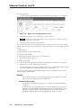
Precautions
Safety Instructions • English
This symbol is intended to alert the user of important operating and maintenance
(servicing) instructions in the literature provided with the equipment.
This symbol is intended to alert the user of the presence of uninsulated dangerous
voltage within the product's enclosure that may present a risk of electric shock.
Warning
Power sources • This equipment should be operated only from the power source indicated on the
product. This equipment is intended to be used with a main power system with a grounded
(neutral) conductor. The third (grounding) pin is a safety feature, do not attempt to bypass or
disable it.
Caution
Power disconnection • To remove power from the equipment safely, remove all power cords from
the rear of the equipment, or the desktop power module (if detachable), or from the power
source receptacle (wall plug).
Read Instructions • Read and understand all safety and operating instructions before using the
equipment.
Power cord protection • Power cords should be routed so that they are not likely to be stepped on or
pinched by items placed upon or against them.
Retain Instructions • The safety instructions should be kept for future reference.
Servicing • Refer all servicing to qualified service personnel. There are no user-serviceable parts
inside. To prevent the risk of shock, do not attempt to service this equipment yourself because
opening or removing covers may expose you to dangerous voltage or other hazards.
Follow Warnings • Follow all warnings and instructions marked on the equipment or in the user
information.
Avoid Attachments • Do not use tools or attachments that are not recommended by the equipment
manufacturer because they may be hazardous.
Slots and openings • If the equipment has slots or holes in the enclosure, these are provided to
prevent overheating of sensitive components inside. These openings must never be blocked by
other objects.
Lithium battery • There is a danger of explosion if battery is incorrectly replaced. Replace it only
with the same or equivalent type recommended by the manufacturer. Dispose of used batteries
according to the manufacturer's instructions.
Consignes de Sécurité • Français
Avertissement
Ce symbole sert à avertir l’utilisateur que la documentation fournie avec le
matériel contient des instructions importantes concernant l’exploitation et la
maintenance (réparation).
Alimentations• Ne faire fonctionner ce matériel qu’avec la source d’alimentation indiquée sur
l’appareil. Ce matériel doit être utilisé avec une alimentation principale comportant un fil de
terre (neutre). Le troisième contact (de mise à la terre) constitue un dispositif de sécurité :
n’essayez pas de la contourner ni de la désactiver.
Ce symbole sert à avertir l’utilisateur de la présence dans le boîtier de l’appareil de
tensions dangereuses non isolées posant des risques d’électrocution.
Déconnexion de l’alimentation• Pour mettre le matériel hors tension sans danger, déconnectez tous
les cordons d’alimentation de l’arrière de l’appareil ou du module d’alimentation de bureau (s’il
est amovible) ou encore de la prise secteur.
Attention
Lire les instructions• Prendre connaissance de toutes les consignes de sécurité et d’exploitation avant
d’utiliser le matériel.
Conserver les instructions• Ranger les consignes de sécurité afin de pouvoir les consulter à l’avenir.
Respecter les avertissements • Observer tous les avertissements et consignes marqués sur le matériel ou
présentés dans la documentation utilisateur.
Eviter les pièces de fixation • Ne pas utiliser de pièces de fixation ni d’outils non recommandés par le
fabricant du matériel car cela risquerait de poser certains dangers.
Protection du cordon d’alimentation • Acheminer les cordons d’alimentation de manière à ce que
personne ne risque de marcher dessus et à ce qu’ils ne soient pas écrasés ou pincés par des objets.
Réparation-maintenance • Faire exécuter toutes les interventions de réparation-maintenance par un
technicien qualifié. Aucun des éléments internes ne peut être réparé par l’utilisateur. Afin
d’éviter tout danger d’électrocution, l’utilisateur ne doit pas essayer de procéder lui-même à ces
opérations car l’ouverture ou le retrait des couvercles risquent de l’exposer à de hautes tensions
et autres dangers.
Fentes et orifices • Si le boîtier de l’appareil comporte des fentes ou des orifices, ceux-ci servent à
empêcher les composants internes sensibles de surchauffer. Ces ouvertures ne doivent jamais
être bloquées par des objets.
Lithium Batterie • Il a danger d'explosion s'll y a remplacment incorrect de la batterie. Remplacer
uniquement avec une batterie du meme type ou d'un ype equivalent recommande par le
constructeur. Mettre au reut les batteries usagees conformement aux instructions du fabricant.
Sicherheitsanleitungen • Deutsch
Vorsicht
Dieses Symbol soll dem Benutzer in der im Lieferumfang enthaltenen
Dokumentation besonders wichtige Hinweise zur Bedienung und Wartung
(Instandhaltung) geben.
Stromquellen • Dieses Gerät sollte nur über die auf dem Produkt angegebene Stromquelle betrieben
werden. Dieses Gerät wurde für eine Verwendung mit einer Hauptstromleitung mit einem
geerdeten (neutralen) Leiter konzipiert. Der dritte Kontakt ist für einen Erdanschluß, und stellt
eine Sicherheitsfunktion dar. Diese sollte nicht umgangen oder außer Betrieb gesetzt werden.
Dieses Symbol soll den Benutzer darauf aufmerksam machen, daß im Inneren des
Gehäuses dieses Produktes gefährliche Spannungen, die nicht isoliert sind und
die einen elektrischen Schock verursachen können, herrschen.
Stromunterbrechung • Um das Gerät auf sichere Weise vom Netz zu trennen, sollten Sie alle
Netzkabel aus der Rückseite des Gerätes, aus der externen Stomversorgung (falls dies möglich
ist) oder aus der Wandsteckdose ziehen.
Achtung
Lesen der Anleitungen • Bevor Sie das Gerät zum ersten Mal verwenden, sollten Sie alle Sicherheitsund Bedienungsanleitungen genau durchlesen und verstehen.
Aufbewahren der Anleitungen • Die Hinweise zur elektrischen Sicherheit des Produktes sollten Sie
aufbewahren, damit Sie im Bedarfsfall darauf zurückgreifen können.
Befolgen der Warnhinweise • Befolgen Sie alle Warnhinweise und Anleitungen auf dem Gerät oder in
der Benutzerdokumentation.
Keine Zusatzgeräte • Verwenden Sie keine Werkzeuge oder Zusatzgeräte, die nicht ausdrücklich vom
Hersteller empfohlen wurden, da diese eine Gefahrenquelle darstellen können.
Instrucciones de seguridad • Español
Schutz des Netzkabels • Netzkabel sollten stets so verlegt werden, daß sie nicht im Weg liegen und
niemand darauf treten kann oder Objekte darauf- oder unmittelbar dagegengestellt werden
können.
Wartung • Alle Wartungsmaßnahmen sollten nur von qualifiziertem Servicepersonal durchgeführt
werden. Die internen Komponenten des Gerätes sind wartungsfrei. Zur Vermeidung eines
elektrischen Schocks versuchen Sie in keinem Fall, dieses Gerät selbst öffnen, da beim Entfernen
der Abdeckungen die Gefahr eines elektrischen Schlags und/oder andere Gefahren bestehen.
Schlitze und Öffnungen • Wenn das Gerät Schlitze oder Löcher im Gehäuse aufweist, dienen diese
zur Vermeidung einer Überhitzung der empfindlichen Teile im Inneren. Diese Öffnungen dürfen
niemals von anderen Objekten blockiert werden.
Litium-Batterie • Explosionsgefahr, falls die Batterie nicht richtig ersetzt wird. Ersetzen Sie
verbrauchte Batterien nur durch den gleichen oder einen vergleichbaren Batterietyp, der auch
vom Hersteller empfohlen wird. Entsorgen Sie verbrauchte Batterien bitte gemäß den
Herstelleranweisungen.
Advertencia
Este símbolo se utiliza para advertir al usuario sobre instrucciones importantes de
operación y mantenimiento (o cambio de partes) que se desean destacar en el
contenido de la documentación suministrada con los equipos.
Alimentación eléctrica • Este equipo debe conectarse únicamente a la fuente/tipo de alimentación
eléctrica indicada en el mismo. La alimentación eléctrica de este equipo debe provenir de un
sistema de distribución general con conductor neutro a tierra. La tercera pata (puesta a tierra) es
una medida de seguridad, no puentearia ni eliminaria.
Este símbolo se utiliza para advertir al usuario sobre la presencia de elementos con
voltaje peligroso sin protección aislante, que puedan encontrarse dentro de la caja
o alojamiento del producto, y que puedan representar riesgo de electrocución.
Desconexión de alimentación eléctrica • Para desconectar con seguridad la acometida de
alimentación eléctrica al equipo, desenchufar todos los cables de alimentación en el panel trasero
del equipo, o desenchufar el módulo de alimentación (si fuera independiente), o desenchufar el
cable del receptáculo de la pared.
Precaucion
Leer las instrucciones • Leer y analizar todas las instrucciones de operación y seguridad, antes de usar
el equipo.
Conservar las instrucciones • Conservar las instrucciones de seguridad para futura consulta.
Obedecer las advertencias • Todas las advertencias e instrucciones marcadas en el equipo o en la
documentación del usuario, deben ser obedecidas.
Evitar el uso de accesorios • No usar herramientas o accesorios que no sean especificamente
recomendados por el fabricante, ya que podrian implicar riesgos.
Protección del cables de alimentación • Los cables de alimentación eléctrica se deben instalar en
lugares donde no sean pisados ni apretados por objetos que se puedan apoyar sobre ellos.
Reparaciones/mantenimiento • Solicitar siempre los servicios técnicos de personal calificado. En el
interior no hay partes a las que el usuario deba acceder. Para evitar riesgo de electrocución, no
intentar personalmente la reparación/mantenimiento de este equipo, ya que al abrir o extraer las
tapas puede quedar expuesto a voltajes peligrosos u otros riesgos.
Ranuras y aberturas • Si el equipo posee ranuras o orificios en su caja/alojamiento, es para evitar el
sobrecalientamiento de componentes internos sensibles. Estas aberturas nunca se deben obstruir
con otros objetos.
Batería de litio • Existe riesgo de explosión si esta batería se coloca en la posición incorrecta.
Cambiar esta batería únicamente con el mismo tipo (o su equivalente) recomendado por el
fabricante. Desachar las baterías usadas siguiendo las instrucciones del fabricante.
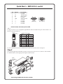
Quick Start — MPX 423 A
Installation
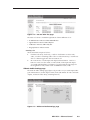
Step 1
Turn off power to the MPX 423 A switcher and all other devices that will be connected.
Step 2
Select your mounting option and install the appropriate brackets. Mount the switcher as illustrated
below (see chapter 2, Installation for detailed instructions).
Drill pilot holes —
3/32” (2 mm) dia.
1/4” (6 mm) deep.
Mounting Screws (2 Plcs)
Each Side
Rack-mount
Bracket
-23
RS
LE
RIB
VA
or
O
IDE
S-V
L
EO
VID
L
ER
UT
MP
CO
L
T
OU
1
O IN
IDE
S-V 11
T
OU
EO
VID 7
I
N
P
U
T
S
L
L
1
2
R
L
4
L
R
L
1
2
R
L
L
3
4
R
L
1
2
R
L
3
4
R
R
3
4
R
R
O
U
T
P
U
T
S
2
C
O
N
T
T
SE
RE
R
K
LIN
O
L ACT
R
R
R
R
R
2
9
12
1
IN
3
O
I
U L
N
T
P
P
L
U
U
T
T
S
S
10
2
ER
UT
MP
CO
T
OU
5
8
6
1
ER
UT
MP
CO
IN
3
2
A
0.3
0V
1
-24
4
100
2
#8 Screw (4 Plcs)
Each Side
Table/
Wall-mount
Bracket
60
Hz
50/
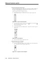
Step 3
Attach up to four VGA, four S-video, and four Video (composite) input devices (up to four of each
type) to the MPX 423 A switcher.
Step 4
Connect up to two VGA, two composite video, or two S-video outputs from the switcher to a projector
or other output device. See the following page for an installation diagram.
Step 5
For audio input, connect up to 12 audio sources to the audio inputs of the VGA, Video
(composite), or S-video groups (up to four audio sources for each group). Refer to Chapter 2,
Installation, for wiring diagrams.
Step 6
For audio output, connect up to two audio output devices. Refer to Chapter 2, Installation, for wiring
diagrams.
Step 7
If the MPX 423 A matrix switcher is to be connected to a computer or host controller for remote
control,
1. Connect the host controller’s RS-232 cable to the 9-pin, female RS-232 remote connector of the
switcher (see pinout table on the following page).
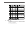
Quick Start — MPX 423 A, cont’d
Pin
1
2
3
4
5
6
7
8
9
RS-232
—
Tx
Rx
—
Gnd
—
—
—
—
Description
not used
Transmit data
Receive data
not used
Signal ground
not used
not used
not used
not used
5
1
9
6
Female
(MPX 423 IP)
1
5
9
Male
(Host controller)
6
RS-232 remote connector pinout table
And/or
2. Plug one end of a Cat 5, straight-through Ethernet cable to the RJ-45 LAN port of the switcher. See
below for pinout instructions.
Clip Down
12345678
Straight-through cable
RJ-45
connector
Side 1
Pin Wire color
12345678
Twisted
Pairs
Pin
Side 2
Wire color
1 White-orange
1 White-orange
2
Orange
2
3
White-green
3
White-green
4
Blue
4
Blue
5
White-blue
5
White-blue
6
Green
6
Green
7
White-brown
7
White-brown
8
Brown
8
Brown
Orange
7&8
1&2 3&6 4&5
For more detailed information, see the Remote Control Port (RS-232) section in chapter 5.
Step 8
Power up the input and output devices, then connect power to the rear AC connector of the switcher.
For further details, see the appropriate chapters in this manual.
TCP/IP
Network
Extron
MPX 423 A
Media Presentation
Matrix
RS
E
IBL
VAR
O
IDE
S-V
L
EO
VID
L
R
UTE
MP
CO
L
T
OU
1
O IN
IDE
S-V 11
T
OU
IN
I
N
P
U
T
S
L
L
1
2
R
L
3
4
L
R
L
1
2
R
L
4
R
L
1
2
L
3
4
O
I
U L
N
T
P
P
L
U
U
T
T
S
S
3
4
R
R
O
U
T
P
U
T
S
2
-23
Speakers
C
O
N
T
T
SE
RE
R
K
LIN
O
L ACT
R
R
R
R
R
12
Amplifier
10
2
T
R OU
UTE
MP
CO
R
R
2
9
1
EO
VID 7
L
3
R
5
8
6
1
R IN
UTE
MP
CO
3
0.3A
240V
100-
1
2
4
2
0 Hz
50/6
PC (2)
Projector
Plasma Monitor
DVD (4)
Laptop (2)
VCR (4)
Connecting the MPX 423 A matrix switcher
Table of Contents
Chapter 1 • Introduction .................................................................................
1-1
About this Manual ............................................................................................................. 1-2
About the MPX 423 A ....................................................................................................... 1-2
Features ................................................................................................................. 1-2
Chapter 2 • Installation .......................................................................................................... 2-1
Mounting the Switcher .................................................................................................... 2-2
Tabletop use ....................................................................................................................... 2-2
Rack mounting the switcher ............................................................................................. 2-2
Furniture mounting the switcher ...................................................................................... 2-2
Rear Panel Connectors ..................................................................................................... 2-3
PRELIMINARY
Connecting the MPX 423 A Matrix Switcher ......................................................... 2-4
RS-232 and Ethernet Control ......................................................................................... 2-5
Chapter 3 • Operation ............................................................................................................. 3-1
Front Panel Operation ...................................................................................................... 3-2
Switcher Modes and Operation ................................................................................... 3-3
Introduction to Single Switcher mode .............................................................................. 3-3
Introduction to Separate Switcher mode ......................................................................... 3-3
Establishing a tie ................................................................................................................ 3-3
Reading the LEDs ............................................................................................................... 3-4
Determining the current switcher mode .......................................................................... 3-4
Using the Switching mode ................................................................................................ 3-4
Front panel security lockout .............................................................................................. 3-5
RGB Delay ........................................................................................................................... 3-5
Genlock Sync ...................................................................................................................... 3-6
Audio ......................................................................................................................................... 3-6
Establishing an audio tie ................................................................................................... 3-5
Audio breakaway ......................................................................................................... 3-6
Volume control (output 1 only) ........................................................................................ 3-7
Audio mute (output 1 only) .............................................................................................. 3-7
Resetting the Unit .............................................................................................................. 3-7
Hardware reset modes ...................................................................................................... 3-7
Factory reset modes ........................................................................................................... 3-8
Chapter 4 • Windows®-based Control Program ..................................................... 4-1
This chapter is not available in this preliminary version.
MPX 423 A • Table of Contents
i
Table of Contents, cont’d
Chapter 5 • Programmer’s Guide ..................................................................................... 5-1
Remote Control Port (RS-232) ....................................................................................... 5-2
Host-to-MPX 423 Communications ............................................................................ 5-2
Using the command/response table ................................................................................. 5-2
Symbol definitions .............................................................................................................. 5-3
Error responses ................................................................................................................... 5-5
References to errors ........................................................................................................... 5-5
Copyright information ....................................................................................................... 5-5
Command/Response Table .............................................................................................. 5-6
Chapter 6 • Ethernet Control ............................................................................................. 6-1
Accessing and Using the Web Server ........................................................................ 6-2
Status .................................................................................................................................. 6-3
System Status page ............................................................................................................. 6-3
DSVP page ........................................................................................................................... 6-3
Configuration ..................................................................................................................... 6-4
System Settings page .......................................................................................................... 6-4
Passwords ............................................................................................................................ 6-6
Firmware upgrade page ..................................................................................................... 6-6
File management ............................................................................................................... 6-7
Control ................................................................................................................................ 6-8
Set and View ties page ....................................................................................................... 6-8
View & Audio Settings page .............................................................................................. 6-9
Special Characters ............................................................................................................ 6-13
Appendix A • Reference Information .......................................................................... A-1
Specifications ....................................................................................................................... A-2
Part Numbers ....................................................................................................................... A-6
Included parts ................................................................................................................... A-6
Optional accessories ......................................................................................................... A-6
Cables ................................................................................................................................ A-6
Bulk cable ........................................................................................................................... A-6
Assorted connectors ........................................................................................................... A-7
Pre-cut cables ..................................................................................................................... A-7
All trademarks mentioned in this manual are the properties of their respective owners.
68-972-01 Rev. A
Printed in the USA
08 04
ii
MPX 423 A • Table of Contents
PRELIMINARY
Navigating the Default Web Pages ............................................................................ 6-3
MPX 423 A
1
Chapter One
Introduction
About this Manual
About the MPX 423 A
Features
Introduction
About this Manual
This manual discusses how to install and operate the Extron MPX 423 A Media
Presentation Matrix Switcher.
About the MPX 423 A
The Extron MPX 423 A is a media presentation matrix switcher that merges three
independent matrix switchers into a single, compact enclosure: a 4x2 VGA switcher,
a 4x2 composite video switcher, and a 4x2 S-video switcher. In addition, the
MPX 423 A offers a 12x2 stereo audio switcher. The MPX 423 A supports both single
and separate switching modes.
Ideal for expanding the input capabilities of a typical LCD or DLP projector, the
MPX 423 A provides a second set of outputs for local or preview monitoring, or a
second presentation system.
The MPX 423 A has 15-pin HD input connectors for VGA signals, BNC input
connectors for composite video signals and 4-pin mini DIN input connectors for
S-video signals. Audio uses 5-pole, 3.5 mm captive-screw connectors shared
between three input groups, and features balanced and unbalanced wiring.
The user has a choice of three control options:
1.
Front panel touch button control
2.
RS-232 using a Windows®-based control program (WCP) or SIS commands
4.
Ethernet control (using Telnet, WCP, or the on-board Web server)
Features
Multiple video inputs — Twelve inputs including four VGA (or SVGA, UXGA,
RGBHV, RGBS, RGsB, or RsGsBs) inputs on 15-pin HD female connectors, four
S-video (NTSC, PAL, or SECAM) inputs on 4-pin mini DIN female connectors,
and four composite video (NTSC, PAL, or SECAM) inputs on BNC female
connectors.
Multiple video outputs — Two outputs per video format for simultaneous (in
Separate mode), or one at a time (in Single mode) display on VGA, composite
video, or S-video devices.
Audio switcher — The 12x2 audio switcher selects among the audio outputs of
each of the three signal groups.
Audio breakaway — The MPX 423 A provides the capability to break away an
audio signal from its corresponding video signal. Audio breakaway switching
can be done via the front panel, Ethernet, or RS-232.
Multiple audio inputs and outputs — Twelve balanced/unbalanced stereo inputs
and two balanced/unbalanced stereo outputs, all using 3.5 mm, 5-pole captive
screw connectors.
Single Switcher mode — Allows for one-touch switching. When one of the 12
inputs is accessed, the signals of the input will be routed to the outputs of its
group. Outputs of the other groups are disconnected, while audio output
remains unaffected.
Separate Switcher mode — Allows for independent switching to the output of any
given I/O group. This effectively divides the MPX 423 A into three separate
switchers in one box.
1-2
MPX 423 A • Introduction
Current configuration memory — Allows for ties and audio settings to be saved in
nonvolatile memory. When the switcher is powered off and then on again, the
switcher recalls the connections made on the last configuration, including
audio settings.
IP Link™ — IP Link-enabled products offer an integrated Web server with high
performance architecture, global compatibility with industry standard
Ethernet communication protocols, multi-user support, and a Web-based asset
management application specifically designed to work with products that
include IP Link technology.
RS-232 remote control — Allows remote control of the MPX switcher using
Extron’s Simple Instruction Set SIS™), Extron’s control software for Windows®,
or a third-party control system.
Downloadable firmware updates — The latest firmware can be conveniently
downloaded from the Extron Web site, and updates for new features and
capabilities can be easily upgraded through the RS-232 or the IP Link Ethernet
port.
Bandwidth — Bandwidth is 350 MHz (-3 dB), typical for VGA video, allowing this
switcher to switch everything from NTSC video to high-resolution computer
displays.
Front panel security lockout — Locks out all front panel functions except for
input/output tie viewing to prevent unwanted setting changes.
Genlock Sync (for composite and S-video) — Includes video genlock capabilities
allowing for vertical interval switching and smooth, glitch-free transitions.
Digital Sync Validation Processing (DSVP™) — Includes Extron's exclusive DSVP,
which allows for the monitoring of input signal status information, as well as
the scan rate for computer signal inputs.
Input audio gain and attenuation (adjustable via RS-232) — Allows users to set the
level of audio gain or attenuation (-18 dB to +24 dB). Individual input audio
levels may be adjusted so there are no noticeable volume differences when
switching between sources.
Speed-sensitive volume control — Automatic sensitivity control allows the user to
easily fine-tune the audio volume.
Versatile mounting options — The MPX 423 A is housed in a rugged, 1U, full rack
width metal enclosure, and can be easily mounted into any rack or podium, or
under a desk.
Internal international power supply — The autoswitchable, internal power supply
provides worldwide power compatibility.
MPX 423 A • Introduction
1-3
Introduction
1-4
MPX 423 A • Introduction
MPX 423 A
2
Chapter Two
Installation
Mounting the Matrix Switcher
Rear Panel Connectors
Connecting the MPX 423 A Matrix Switcher
RS-232 and Ethernet Control
MPX 423 A • Introduction
Installation
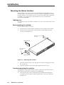
Mounting the Matrix Switcher
The MPX 423 A is housed in 1U high, 17.4” wide metal enclosures that are rack- or
desk-mountable. The appropriate rack/desk mounting kit (#70-077-03) is included
with the switchers. The switchers may also be surface-mounted under a table, desk,
or podium, or on a wall, using an optional Extron 1U enclosure under-desk
mounting kit (#70-222-01).
Tabletop use
For tabletop use, affix a self-adhesive rubber foot to each corner of the bottom of the
switcher.
Rack mounting the switcher
Rack mount the switcher as follows:
1.
If feet were previously installed on the bottom of the switcher, remove them.
2.
Attach the rack mount brackets to the switcher with the eight #8 machine
screws provided (figure 2-1).
Mounting Screws (2 Plcs)
Each Side
Optional Bracket
RS
E
RIBL
VA
O
DE
S-VI
L
O
VIDE
or
L
R
TE
MPU
CO
L
T
OU
1
#8 Screw (4 Plcs)
Each Side
O IN
DE
S-VI 11
T
OU
L
L
1
2
R
L
3
4
L
R
L
1
2
R
L
4
R
L
1
2
R
L
3
4
R
R
3
4
R
R
O
U
T
P
U
T
S
-232
C
O
N
T
T
SE
RE
R
LINK
O
L ACT
R
R
R
R
R
2
9
12
1
O IN
VIDE 7
I
N
P
U
T
S
L
3
O
I
U L
N
T
P
P
L
U
U
T
T
S
S
10
2
T
R OU
TE
MPU
CO
5
8
6
1
R IN
TE
MPU
CO
3
0.3
10
0-2
40
V
2
A
1
4
2
50
/60
Hz
Supplied Bracket
Figure 2-1 — Mounting the switcher
3.
Insert the switcher into the rack, align the holes in the mounting bracket with
those of the rack.
4.
Secure the switcher to the rack using the supplied machine screws.
Furniture mounting the switcher
The MPX 423 A can be mounted under a table or other horizontal surface with an
optional Extron under-desk mounting kit (part #70-222-01).
1.
2-2
Secure the two table/wall mounting brackets included in the under-desk
mounting kit to the switcher with the eight machine screws provided in the
kit (figure 2-1).
MPX 423 A • Installation
2.
Hold the switcher with attached brackets against the underside of the desk or
other furniture. Mark the location of holes for screws on the underside of the
desk.
3.
Drill 1/4" (6.4 mm) deep, 3/32" (2 mm) diameter pilot holes in the table or
desk at the marked screw locations from the underside/inside (concealed
side) of the furniture, where the switcher will be located.
4.
Insert the four wood screws into the pilot holes. Fasten each screw into the
installation surface until just less than 1/4" of the screw head protrudes.
5.
Align the installed screws with the slots in the mounting brackets, and place
the switcher against the surface, with the screws through the bracket slots.
6.
Slide the switcher slightly forward or back, then tighten all four screws to
fasten it in place.
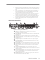
Rear Panel Connectors
100-240V
5
3
1
COMPUTER IN
0.3A
COMPUTER OUT
5
50/60 Hz
1
3
1
2
4
2
2
6
VIDEO IN
7
8
OUT
1
2
9
10
S-VIDEO IN
11
12
OUT
1
2
12
11
7
COMPUTER
I
N
P
U
T
S
VIDEO
S-VIDEO
RS-232
VARIABLE
L
1
R
L
3
R
L
5
R
L
7
R
L
9
R
L
11
R
L
2
R
L
4
R
L
6
R
L
8
R
L
10
R
L
12
R
I
N
P
U
T
S
O
U
T
P
U
T
S
L
3
R
L R R
O
U
T
P
U
T
S
C
O
N
T
R
O
L
LAN
15
ACT
4
6
8
9
10
LINK RESET
13
14
Figure 2-3 — Rear panel of MPX 423 A
1
AC power — Standard AC power connector for a power source of
100 – 240VAC, operating at 50/60 Hz.
2
VGA input group — Four female 15-pin HD connectors for RGB video input
(numbered 1 to 4).
3
VGA output — Two female 15-pin HD connectors for RGB video output.
4
Composite input group — Four female BNC connectors for composite input
(numbered 5 to 8).
5
Composite output — Two female BNC connectors for composite output.
6
S-video input group — Four female 4-pin Mini DIN connectors for S-video
input (numbered 9 to 12).
7
S-video output — Two female 4-pin Mini DIN connectors for S-video output.
8
VGA audio input — Four 3.5 mm female captive screw connectors for audio
input from the VGA group. For more information, see Audio in Chapter 3,
Operation.
9
Composite audio input group — Four 3.5 mm, female, captive screw
connectors for the composite group input. For more information, see Audio in
Chapter 3, Operation.
10
S-video audio input group — Four 3.5 mm, female, captive screw connectors
for the S-video group input. For more information, see Video/audio group
button in Chapter 3, Operation.
11
Variable audio output — Two 3.5 mm, female, captive screw connectors for
balanced/unbalance variable audio output.
MPX 423 A • Installation
2-3
Installation, cont’d
12
RS-232 — One female DB9 connector for a host computer or third party
controller using Extron’s Simple Instruction Set (SIS) or Windows® Control
Software.
13
LAN Activity LED — A blinking yellow LED indicates LAN activity.
LAN connector — Plug an RJ-45 jack into this socket to connect the unit to a
computer network. Use a straight-through cable to connect to a switch, hub,
or router.
Link LED — The green LED lights to indicate a good LAN connection.
14
Reset button — A recessed button that allows for a manual reset using a
Extron Tweeker, pointed stylus or ballpoint pen. The unit can be reset to five
modes (see Resetting the Unit in chapter 3 for additional information).
15
Reset LED — The green LED flashes to show the reset mode indicators and
that power is on (see Resetting the Unit in chapter 3 for additional information).
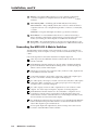
Connecting the MPX 423 A Matrix Switcher
The MPX 423 A matrix switcher can be connected to as many as 12 input devices
simultaneously, and can output to as many as six devices simultaneously, or one at
a time.
Follow the steps below and see the installation example in figure 2-4.
2-4
1
Turn off power to the MPX 423 A matrix switcher and all other devices that
will be connected.
2
If the MPX 423 A matrix switcher is to be rack, table or furniture mounted,
position the brackets and insert the mounting screws. See the Mounting the
Matrix Switcher, earlier in this chapter.
3
Attach up to four VGA, four composite video, and four S-video, input devices
to the MPX 423 A matrix switcher.
4
Connect the switcher’s VGA, Video (composite), and S-video outputs (up to
six, two of each video format) to the inputs of the display(s).
5
For audio input, connect up to 12 audio sources to the switcher’s audio inputs
of the VGA, Video (composite), or S-video groups (up to 4 for each group).
See figure 2-4 for a connection diagram.
6
For audio output, connect an audio output device to each of the two audio
outputs. See Audio outputs in chapter 3, Operation for wiring diagrams.
7
If the MPX 423 A matrix switcher is to be connected to a computer or host
controller for remote control, connect the host’s RS-232 cable to the 9-pin
female RS-232 connector of the MPX unit. For an RS-232 pinout table, see the
RS-232 and Ethernet Control later in this chapter.
8
For an Ethernet connection, plug one end of a Cat 5, straight-through Ethernet
cable to the RJ-45 LAN port of the switcher. See RS-232 and Ethernet Control
later in this chapter for pinout instructions.
9
Power up the input and output devices, then connect power to the rear AC
connector of the MPX 423 A matrix switcher.
MPX 423 A • Installation
TCP/IP
Network
Extron
MPX 423 A
Media Presentation
Matrix
RS
E
IBL
VAR
O
IDE
S-V
L
EO
VID
L
R
UTE
MP
CO
L
T
OU
1
O IN
IDE
S-V 11
T
OU
IN
L
L
1
2
R
L
3
4
L
R
L
1
2
R
L
L
3
4
R
L
2
R
L
3
4
R
R
O
I
U
N
T
P
P
U
U
T
T
S
S
L
L
3
4
R
R
O
U
T
P
U
T
S
2
-23
R
R
R
R
R
12
Amplifier
10
2
T
R OU
UTE
MP
CO
Speakers
C
O
N
T
T
SE
RE
R
K
LIN
O
L ACT
2
9
1
EO
VID 7
I
N
P
U
T
S
1
5
8
6
1
R IN
UTE
MP
CO
3
0.3A
240V
100-
1
2
4
2
0 Hz
50/6
PC (2)
Projector
Plasma Monitor
DVD (4)
Laptop (2)
VCR (4)
Figure 2-4 — MPX 423 A installation example
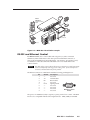
RS-232 and Ethernet Control
For RS-232 control, use a control cable with only pins 2, 3, and 5 connected.
Otherwise, either cut the wires to the other pins in hard-shelled connectors or
remove the unneeded pins from molded plugs. See chapter 5, Programmer’s Guide,
for definitions of the SIS commands and details on how to install and use the
control software.
The cable used to connect the RS-232 port to a computer or control system may
need to be modified by removing pins or cutting wires. If unneeded pins are
connected, communication may not be possible.
The RS-232 connector is a DB9 female with the following pin designations:
Pin
1
2
3
4
5
6
7
8
9
RS-232
Description
—
Tx
Rx
—
Gnd
—
—
—
—
not used
Transmit data
Receive data
not used
Signal ground
not used
not used
not used
not used
5
1
9
6
DB9 Pin Locations
Female
The protocol is 9600 baud, 8-bit, 1 stop bit, no parity, and no flow control. The MPX
423 A is also compatible with the following baud rates: 19200, 38400, and 115200.
MPX 423 A • Installation
2-5
Installation, cont’d
For Ethernet control, Plug one end of a Cat 5, straight-through Ethernet cable to the
RJ-45 LAN port of the switcher. See below for pinout instructions.
Clip Down
12345678
RJ-45
connector
12345678
Twisted
Pairs
Straight-through cable
Side 1
Pin Wire color
Pin
Side 2
Wire color
1 White-orange
1 White-orange
2
Orange
2
3
White-green
3
White-green
4
Blue
4
Blue
5
White-blue
5
White-blue
6
Green
6
Green
7
White-brown
7
White-brown
8
Brown
8
Brown
Orange
7&8
1&2 3&6 4&5
For more detailed information, see the Remote Control Port (RS-232) section in
chapter 5.
2-6
MPX 423 A • Installation
MPX 423 A
3
Chapter Three
Operation
Front Panel Operation
Switcher Modes and Operation
Audio
Resetting the Unit
MVP 104GX Installation
Operation
Front Panel Operation
2
1
3
5
4
MPX 423 A
COMPUTER
VIDEO
INPUTS
OUTPUTS/
AUDIO
1
2
OUTPUTS
3
S-VIDEO
INPUTS
5
4
6
OUTPUTS
7
MEDIA PRESENTATION MATRIX
INPUTS
9
8
10
11
12
I/O
MUTE
VOLUME
1
1
1
VIDEO
2
2
2
AUDIO
MODE
SINGLE
SEPARATE
6
7
8
AUDIO OUTPUT 1
9
10
11
12
Figure 3-1 — Front panel details of the MPX 423 A matrix switcher
The following sections describe the front panel controls. The controls for the three
independent switchers are grouped by input type.
1
VGA output — These two green LEDs serve three functions:
• Displays VGA video output activity.
• Indicates which audio output is active.
• Indicates output selection when setting the switching mode.
2
VGA input — Buttons 1 through 4 select the input for the VGA input sections
of the MPX unit. The LEDs adjacent to each button (when lit) indicate which
input has been selected for output.
3
Composite video output — Displays which composite video output (output 1
or output 2) is currently active.
4
S-video output — Displays which S-video output (output 1 or output 2) is
currently active.
5
I/O — This button serves four functions:
• Allows for toggling between video and audio modes, and simultaneous
video/audio functionality.
• Provides a method of accessing the Front Panel Security Lockout function.
• Acts as a system reset button.
• Functions with the Mute button to set an RGB delay.
3-2
6
Mode — This is the secondary function of this button (see 2 ). The mode
function of this button allows the MPX 423 A to be used in either “single” or
“separate” mode.
7
Single Switcher mode — This is the secondary function of this button (see
2 ). Press and release this button when in “switching mode” (see Using the
switching mode later in this chapter) to select the Single Switcher mode. The
associated LED indicates if the Single Switcher mode is on (when flashing).
When the Mode button is released, the LED will resume input indication.
8
Separate Switcher mode — This is the secondary function of this button
(see 2 ). Press and release this button to select the Separate Switcher mode.
The associated LED indicates if the Separate Switcher mode is on (when
flashing). When the Mode button is released, the LED will resume input
indication.
MPX 423 A • Operation
9
Composite video input — Buttons 5 through 8 select the input for the
composite video sections of the MPX unit. The LEDs adjacent to each button
(when lit) indicate which input has been selected for output.
10
S-video input — Buttons 9 through 12 select the input for the S-video group
of the MPX unit. The LEDs adjacent to each button (when lit) indicate which
input has been selected for output 1.
11
Audio mute — This button mutes audio output 1. The LED (when lit)
indicates that audio output 1 is muted.
12
Audio volume — This adjustment knob controls the volume of audio
output 1.
Switcher Modes and Operation
MPX 423 A
COMPUTER
OUTPUTS/
AUDIO
VIDEO
INPUTS
1
2
OUTPUTS
3
S-VIDEO
INPUTS
5
4
6
OUTPUTS
7
MEDIA PRESENTATION MATRIX
INPUTS
9
8
10
11
12
I/O
MUTE
VOLUME
1
1
1
VIDEO
2
2
2
AUDIO
MODE
SINGLE
AUDIO OUTPUT 1
SEPARATE
Figure 3-2 — MPX 423 A matrix switcher front panel
Introduction to Single Switcher mode
In Single Switcher mode, the switcher emulates 1 output switcher with 12 inputs.
When a video input signal is tied to an output, it is routed to the same video signal
format. All other video output signals are muted.
The audio operates independently as a 12 inputs to 2 outputs matrix switcher. See
Audio later in this chapter for more information.
Both outputs can be configured in Single Switcher mode; i.e., the unit
emulates two 1 output switchers with 12 inputs each.
Introduction to Separate Switcher mode
In Separate Switcher mode the switcher emulates three 1 output switchers with 4
inputs. There are three input selection groups on the front panel: Computer, Video
(composite), and S-video. These three groups operate independently from each
other, and each of the twelve inputs can only be routed to its own video output
format group.
The audio operates independently as a 12 inputs to 2 outputs matrix switcher.
Both outputs can be configured in Separate mode; i.e., the unit emulates three
2 output switchers with 4 inputs each.
Establishing a tie
When you connect an input with an output in video or audio, you are establishing a
tie. A tie can be a video-only tie (only a video signal is being transmitted through
an output), an audio-only tie (only an audio signal is being transmitted through an
output) or an audio and video (A/V) tie (a video signal and audio signal are being
transmitted together or apart through one or more outputs).
To establish a tie using the MPX 423 A, do the following:
1.
Press the I/O button to select a video-only, audio-only, or A/V tie.
2.
Select the output using any of the output buttons.
3.
Select the input from any of the 12 inputs.
MPX 423 A • Operation
3-3
Operation, cont’d
Reading the LEDs
Reading the LEDs of the MPX 423 A matrix switcher is the primary means of
controlling your inputs and outputs. The unit uses a series of LED colors and
actions to indicate the status of each group and/or tie.
When in audio-only or video-only mode
• A lit input LED represents a tie.
• The lit I/O LEDs show the signal type (audio or video).
When in A/V mode
• A lit input LED represents a video-only tie.
• A flashing input LED represents an audio tie.
• A flashing audio I/O LED represents audio that follows the video signal.
• An active video LED is always lit.
A flashing output LED represents a muted state.
Determining the current switcher mode
As shown at right, the current switcher
mode is indicated by the front panel input
LEDs of the Computer group.
COMPUTER
INPUTS
1
2
3
MODE
SINGLE
SEPARATE
Using the Switching mode
In order to select or view the single and separate modes of the MPX 423 A, use the
Switching mode. To use this state to check the unit’s current mode status, do the
following:
1.
Select an output (1 or 2).
2.
Press the Mode button for approximately 3 seconds, until the Single and
Separate LEDs light. The flashing LED indicates the active mode.
Here, you can choose between Single and Separate mode, and view which one is
currently active.
In Switching mode, the only active front panel LEDs are those within the Computer
group (Mode, Single, and Separate indicators) shown above and in figure 3-3. This
signifies that the unit is in “mode indication” (i.e., you cannot view the current
inputs). If a selection is not made during this “mode indication” phase, Switching
mode times out.
To change the mode, continue to hold the Mode button and press the button that
corresponds to the setting you want to change. Figure 3-3 on the following page
shows the front panel buttons and LEDs that are active during Switching mode.
Release the Mode button and the front panel LEDs resume input indication.
Changes to the Single Switcher mode and Separate Switcher mode take effect
when the button is released.
3-4
MPX 423 A • Operation
OUTPUTS/
AUDIO
1
COMPUTER
1
OUTPUTS/
AUDIO
2
INPUTS
1
2
3
4
MODE
SINGLE
SEPARATE
MODE
1
2
Select the output
to be configured.
Press and hold
the Mode button
for approximately
3 seconds to
enter Switching
mode.
Press the Single button to
select Single Switcher mode.
S-VIDEO
COMPUTER
OUTPUTS/
AUDIO
OUTPUTS
INPUTS
INPUTS
2
1
3
9
4
10
11
12
1
1
2
2
MODE
SINGLE
SEPARATE
Press the Separate button to
select Separate Switcher
mode.
In Separate mode, any input
in a group (in this example
input 10 of the S-video/Audio
group) can be independently
accessed. When the input is
active the LED lights up.
Figure 3-3 — Front panel button/LED functions during Switching mode
Front panel security lockout
Front panel security lockout prevents accidental switching of inputs from the front
panel. When front panel security lockout is active, the user can only view the ties in
each group; all input buttons and audio functions are locked.
To toggle the front panel lockout on and off, press and hold the I/O button for three
seconds. All front panel LEDs flash once to indicate acceptance. When front panel
lockout is on, the user can still view the ties by toggling the I/O and output
buttons. The LEDs of the corresponding inputs light up according to their tie
modes.
If you attempt to make a tie in this mode, the two LEDs of the I/O button flash
twice, indicating that no ties can be made from the front panel. RS-232 and Ethernet
controls are not affected in this mode.
RGB Delay
The RGB Delay feature clears the screen when the MPX 423 A switches to a new
source. The new sync signals precede the RGB signals, so there is no glitch shown
during the transition. The time delay between the RGB and sync signals is
adjustable in half-second steps of up to five seconds. It can be controlled via RS -232
or the front panel.
To use the front panel to set an RGB delay, do the following:
1.
Press and hold the I/O and Mute buttons simultaneously for three seconds.
The Video and Output 1 or 2 LEDs flash.
2.
Select an output to set, or read the delay settings.
3.
Use the volume knob to increase or decrease the delay time. Each input LED
lit represents a 0.5 second delay.
4.
Press and hold the I/O button to exit.
MPX 423 A • Operation
3-5
Operation, cont’d
For information on setting the RGB Delay through Ethernet control, see Accessing
and Using the Web Server in chapter 6 and the SIS commands listed in chapter 5,
Programmer’s Guide.
Genlock Sync
When switching between inputs in the Video and S-video groups, vertical interval
switching is possible. When all input signals are “genlocked” together, the Genlock
feature prevents glitches in the video images. The signal connected to input 5
(within the Video group) and input 9 (of the S-Video group) will be used as the
reference signal for switching between inputs during the vertical interval.
Audio
The MPX 423 A is also a 12x2 audio matrix switcher, where any of the 12 inputs can
be routed to one or both outputs simultaneously.
Establishing an audio tie
Regardless of the switching mode to which the unit is configured (single or
separate), the audio behaves like a 12x2 switcher.
To make an audio-only tie, do the following:
1.
Select the output using any of the three output buttons. Each of the three
output buttons can be toggled between output 1 and output 2.
In the audio mode the output buttons are synchronized; i.e., the LEDs indicate
the same output number.
2.
Select the audio signal mode using the I/O button.
3.
Select any of the 12 inputs.
When one of the 12 input buttons is pressed and released, the audio signal of this
input will be routed to whichever audio output is selected.
When establishing an audio tie, please note:
• The two front panel audio controls only control the audio level of
output 1.
• A flashing LED indicates an audio tie.
• When input LEDs and audio I/O LEDs are flashing simultaneously, the
audio and the video signals and not in audio breakaway.
Audio breakaway
Audio breakaway allows you to route the audio signal separately from the video
signal. Any audio signal can be selected with any video signal to one or all outputs
in any combination, simultaneously.
Audio breakaway switching can be done via front panel control, through RS-232, or
via Ethernet remote control.
Volume control (Output 1 only)
Use the Audio Volume control knob to adjust the volume of the audio output. By
turning the knob clockwise, the volume increases at a rate of 1dB per step of the
digital potentiometer. Turning the knob counterclockwise will decrease the output
level.
Control of audio output 2 is available through RS-232 or Ethernet/Telnet only.
3-6
MPX 423 A • Operation
The volume adjustment is speed sensitive. To avoid large audible volume jumps
when the volume knob is turned quickly, the volume changes by smaller steps.
Audio mute (Output 1 only)
The Mute button toggles between mute and un-mute for audio output 1. The
indicator LED to the right of the button lights when the audio is muted. If a muted
output is not at maximum attenuation, it is disconnected. Press the Audio Mute
button again to un-mute the output and return to the previous output level.
Control of audio output 2 is available through RS-232 or Ethernet/Telnet only.
Audio outputs
Balanced or unbalanced audio output is available on the MPX 423 A using a
3.5 mm, 5-pole captive screw connector. Refer to the following illustration for
proper wiring.
Tip
Ring
Sleeve (s)
Tip
Ring
Tip
See caution
Sleeve
Tip
See caution
Unbalanced Output
Balanced Output
Figure 2-5 — 3.5 mm, 5-pole captive screw audio connectors
CAUTION
Connect the sleeve to ground (Gnd). Connecting the sleeve to a negative
(-) terminal damages the audio output circuits.
Resetting the Unit
There are four reset modes activated by the Reset button in the back of the unit.
The Reset button is recessed, so use of a pointed stylus, ballpoint pen, or Extron
Tweeker is suggested.
The I/O button on the front panel also has limited reset capabilities, described on
the following page.
Hardware reset modes
CAUTION
The reset modes listed below close all open IP and Telnet connections, and
all sockets.
If the Reset button is continuously held down, the rear panel LED pulses
(blinks) every 3 seconds and puts the unit in a different mode (corresponding
to the underscored notes in Modes 3 through 5). The third blink indicates the
last mode, Mode 5, so the LED blinks three times. The following modes are
listed as separate functions, not as a continuation from Mode 1 to Mode 5.
Mode 1: Holding the Reset button while applying power defaults the unit back to
the base firmware that shipped with the unit from the factory. Event scripting
does not start when the unit is powered on in this mode. This allows you to
recover a unit that has incorrect code or updated firmware running. All user
files and settings are maintained. User Web pages may not work correctly if
the unit is using an earlier firmware version.
MPX 423 A • Operation
3-7
Operation, cont’d
Mode 3: Holding the Reset button until the I/O LED blinks once (3 seconds)
followed by a momentary (<1 second) press turns events either on or off,
depending on the current state of the events:
•
If the events are currently stopped following the momentary (<1 second)
press, the I/O LED will flash twice indicating the starting of events.
or
•
If events are currently running following the momentary (<1 second)
press, the I/O LED flashes three times, indicating the stopping of events.
Each flash lasts for .25 seconds. Nothing happens if the momentary press
does not occur within 1 second.
Mode 4: Holding the Reset button until the I/O LED blinks twice (6 seconds)
followed by a momentary (<1 second) press will reset IP settings. The I/O
LED blinks four times in quick succession, confirming a Mode 4 reset. This
mode
1. Enables ARP program capability
2. Sets IP back to factory IP
3. Sets Subnet back to factory default
4. Sets Gateway back to factory default
5. Sets port mapping back to factory default
6. Turns DHCP off
7. Turns events off
Nothing happens if the momentary press does not occur within one second.
Mode 5: Holding the Reset button until the I/O LED blinks three times
(9 seconds) followed by a momentary (<1 second) press causes a complete
system reset back to factory default conditions. Nothing happens if the
momentary press does not occur within 1 second. The I/O LED blinks four
times in quick succession, confirming a Mode 5 reset.
Factory reset modes
Factory resets can be set using the front panel I/O button. To reset the MPX 423 A
to factory defaults
1.
Press and hold the I/O button on the front panel while plugging in AC power.
2.
Continue to hold the I/O button until all LEDs on the front panel flash.
Once the I/O button is released, power-up continues and the LEDs go back to their
default configuration.
3-8
MPX 423 A • Operation
MPX 423 A
5
Chapter Five
Programmer’s Guide
Remote Control Port (RS-232)
Host-to-MPX Communications
Command/Response Table
MVP 104 Windows Control Program
Programmer’s Guide
Remote Control Port (RS-232)
The MPX 423 A matrix switcher RS-232 port connector is used to connect to a
host or external controlling device, such as a computer or control system,
which can generate the proper command codes and recognize the switcher’s
responses.
5
1
9
6
Female
(MPX 423 IP)
1
5
9
6
Male
(Host controller)
The cable used to connect the RS-232 port to a computer or control system may
need to be modified by removing pins or cutting wires. If unneeded pins are
connected, the switcher may hinder communication. See chapter 2,
Installation, for more information on wiring the connectors.
The RS-232 connector is a DB9 female (see illustration above) with the
following pin designations:
Pin
1
2
3
4
5
6
7
8
9
RS-232
Description
—
Tx
Rx
—
Gnd
—
—
—
—
not used
Transmit data
Receive data
not used
Signal ground
not used
not used
not used
not used
The protocol is 9600 baud, 8-bit, 1 stop bit, no parity, and no flow control.
The MPX 423 A is also compatible with the following baud rates: 19200,
38400, and 115200.
Commands and responses for programming the MPX 423 A from a host
system connected to the RS-232 port are listed on the following pages.
Host-to-MPX Communications
The MPX 423 A matrix switcher accepts SIS™ (Simple Instruction Set)
commands through the RS-232 port or through Telnet. SIS commands consist
of one or more characters per command field. They do not require any
special characters to begin or end the command character sequence. Each
response to an SIS command ends with a carriage return and a line feed
(CR/LF = ), which signals the end of the response character string. A
string is one or more characters.
Using the command/response table
The command/response table is shown on the following pages. Lowercase
characters are acceptable in the command field only where indicated.
Symbols are used throughout the table to represent variables in the
command/response fields. Symbol definitions are shown below, and an
ASCII-to-hexadecimal (HEX) conversion table is shown in figure 5-1.
Command and response examples are shown throughout the command/
response table.
5-2
MPX 423 A • Programmer’s Guide
ASCII to HEX Conversion Table
•
Figure 5-1 — ASCII-to-hexadecimal conversion table
Symbol Definitions
= CR/LF
X1
X2
X3
X4
• = space
= CR (no line feed)
= 0 thru max. number of inputs
(Input 0 = muted output)
= Outputs 1 through 6
(1, 2 = VGA and Audio; 3, 4 = Composite Video; 5,6 = S-Video)
Single switch mode 1 or 2 only
= -18 thru +24
(43 steps of audio gain or attenuation)
= 0 db thru 24 db (audio gain)
X6
= 0 db thru 18 db (audio attenuation)
= Volume adjustment range (0%-100%).
(volume min. = 0 through volume max. = 64)
In 1 dB steps except from 1 to 0 = -30dB
X9
= On/Off status: 0 = off/disable ; 1 = on/enable
X10
= Signal/No Signal: 0 = no signal at input; 1 = signal at input
X11
= 2 = Separate 1; = Single, (switcher mode)
X13
= Delay in ½ second increments (10 max. = 5.0 seconds)
X14
= Video/Audio Mute:
0 = no mute; 1 = video; 2 = audio; 3 = video and audio mute
X15
X16
X17
X18
= escape
= 1 thru max. number of inputs
X5
X7
Esc
= xxx.xx (frequency in Hz or kHz)
= Dirty status: 0 = RAM has been saved to Flash (OK to power off/reset);
1 = RAM needs to be saved to Flash
= 10s of milliseconds wait time for characters coming into a serial
port before terminating (default=10=100ms, max=32767)
= 10s of milliseconds wait time between characters coming into a serial
port before terminating (default=2=20ms, max.=32767)
X19
= Controller firmware version to the second decimal place
X20
= Verbose firmware version – description – upload date/time
MPX 423 A • Programmer’s Guide
5-3
Programmer’s Guide
X22
X25
= Matrix name (24 characters max.)
Invalid characters: + ~ @ = ‘ [ ] { } < > “ ; :| \ ?
X26
= GMT date [WWW,•DD•MMM•YYYY•HH:MM:SS•GMT]
X27
= IP address [###.###.###.###]
X28
= E-mail event number: range = 1 – 64 (Max.)
X29
= Default name: Combination of model-name and last 3 pairs of MAC
address (e.g., MPX-423-A-00-02-3D)
X30
= Password (12 digits, alphanumeric)
X31
= Connection’s security level: 0 = not logged in; 1 = User; 2 = Administrator
X32
= E-mail user name (up to 240 characters). Email name for the matrix
X33
= E-mail address (Uses typical email address format)
X34
= Hardware address [##-##-##-##-##-##]
X35
= 0 –255 number of open connections
X37
= GMT date [MM/DD/YY•HH:MM:SS]
X38
= Domain name [example = extron.com]
X39
= GMT offset (-12.0 through +14.0 hours and minutes removed from GMT).
X40
= Daylight Savings time: 0 = Daylight savings time off/ignore;
1 = Daylight savings time on (northern hemisphere)
X41
= E-mail account [1 through 64]
X45
= DHCP [0 = off, 1 = on]
X46
= Port # 01. The port number will be represented as two ASCII characters
(2 bytes) (e.g., port 01 would be represented as 30 31 in hex)
X47
= Baud rate (9600, 19200, 38400, 115200)
X48
= Parity: Odd, Even, None, Mark, Space (only first letter required).
X49
= Data bits ( 7 or 8)
X50
= Stop bits (1 or 2)
X51
= Port type (0= RS-232)
X52
= Flow control: Hardware, Software, None (only use the first letter)
X53
X54
5-4
= Power supply voltages and Temperature (in degrees, Fahrenheit)
(+5.0V, +3.3V, +2.5V, +15.0V, -5.0V, -15.0V, Temp)
= Data pacing (specified in milliseconds between bytes):
0000 – 1000 (default = 0 ms)
= Web page priority flag (internal use only):
0 = Internal (default on power up); 1 = User
MPX 423 A • Programmer’s Guide
Error responses
When the MPX 423 A matrix switcher receives an SIS command and
determines that it is valid, it performs the command and sends a response to
the host device. If the switcher is unable to perform the command because
the command is invalid or contains invalid parameters, it returns an error
response to the host. The error response codes are:
E01
— Invalid input channel number
E10
— Invalid command
E11
— Invalid preset number
E12
— Invalid output number / Invalid port number
E13
— Invalid parameter
E14
— Command not available for matrix configuration
E17
— Timeout (only caused by direct write of global presets)
E22
— Busy
E24
— Privilege violation (Ethernet, Extron software only) User
privileges have access to ALL view and read commands, and
the following:
•
•
•
Create Ties
Create and Recall Presets
Set RGB and Audio Mutes
Exception to the rule: User cannot read Admin Password
E25
— Device not present
E26
— Maximum number of connections exceeded
E27
— Invalid Event number
E28
— Bad Filename / File not found
References to errors
24
= Commands that give E24 (privilege violation) if not administrator level.
Copyright information
(c) Copyright 2004, Extron Electronics, MPX 423 A, Vx.xx
The copyright message is initiated by the MPX 423 A matrix switcher when it
is first powered on. Vx.xx is the firmware version number.
MPX 423 A • Programmer’s Guide
5-5
Programmer’s Guide, cont’d
Command/response table for Simple Instruction Set (SIS) commands
Command
ASCII
Hex
Unit response
Input selection (in Single and Separate Switcher modes)
Tie input (A and V)
X2
* X3 !
( X2 +30h) 2A ( X3 +30h) 21
Tie input RGBHV (VGA)
X2
* X3 &
( X2 +30h) 2A ( X3 +30h) 26
Out X3 •In X2 •All
Out X3 •In X2 •RGB
Tie input video
X2
* X3 %
( X2 +30h) 2A ( X3 +30h) 25
Out X3 •In X2 •Vid
Tie input audio
X2
* X3 $
( X2 +30h) 2A ( X3 +30h) 24
Out X3 •In X2 •Aud
( X2 +30h) 2A 24
In X2 •Aud
Tie an input to all outputs (audio only):
X2 *$
View
Video output tie
X3
%
( X3 +30h) 25
X2
RGBHV output tie
X3
&
( X3 +30h) 26
X2
Audio output tie
X3
$
( X3 +30h) 24
X2
Audio gain for input
X1 G
( X1 +30h) 47
X4
Audio volume for output
X3 V/v
( X3 +30h) 56/76
X7
Switcher Mode Select
Switcher mode selection
X3 * X11 *1#
2A ( X3 +30h) 2A ( X11 +30h) 31 23
X3 Swm X11
View Switcher mode
X3 *1#
( X3 +30h) 31 2A 23
X11
Note: 1: Switcher mode selection
X11: 1 = Single Mode; 2= Separate Mode (default mode)
Setting Input Audio Gain/Attenuation
Positive (+db)
X1 * X5
G
( X1 +30h) 2A ( X5 +30h) 47
In X1 •Aud X4
Attenuation (-db)
X1 * X6
g
( X1 +30h) 2A ( X6 +30h) 67
In X1 •Aud X4
Increment
X1 +G
( X1 +30h) 2B 47
In X1 •Aud X4
Decrement
X1 -G
( X1 +30h) 2D 47
In X1 •Aud X4
View input gain
X3 G/g
( X1 +30h) 47
X4
Setting output audio volume
Increment
X3 +V/v
( X3 +30h) 2B 56/76
Out X3 •Vol X7
Decrement
X3 -V/v
( X3 +30h) 2D 56/76
Out X3 •Vol X7
Output level
X3 * X7 V/v
( X3 +30h) 2A ( X7 +30h) 56/76
Out X3 •Vol X7
View volume
X3 V
( X3 +30h) 56
X7
Audio mute
X3 *1Z/z
( X3 +30h)2A 315A/7A
Amt X3 *1
Audio un-mute
X3 *0Z/z
( X3 +30h)2A 30 5A/7A
Amt X3 *0
Audio mute
Read audio mute
X3 Z/z
( X3 +30h)5A/7A
X9
Mute On
1*Z/z
31 2A 5A/7A
Amt 1
Mute Off
0*Z/z
30 2A 5A/7A
Amt 0
( X3 +30h ) 2A ( X13 +30h) 44/64 0D
Out X3 •Dly X13
RGB Delay (Triple Action Switching)
Set RGB Delay
ESC X3 * X13 D/d
1B
Read RGB Delay
ESC X3 D/d
1B ( X3 +30h) 44/64 0D
X13
RGB/Video Mute
X3 *1B/b
( X3 +30h) 2A 31 42/62
Vmt X3 *1
RGB/Video Un-mute
X3 *0B/b
( X3 +30h) 2A 30 42/62
Vmt X3 *0
RGB/VIDEO Mute
5-6
MPX 423 A • Programmer’s Guide
Command
ASCII
Read RGB/VideoMute
X3
B/b
Hex
Unit response
( X3 +30h) 42/62
X9
Note: User may also use input 0 (zero) for mute (i.e., 0*1! = mutes output 1
for Video and Audio).
View Output Mutes
ESC VM
1B 56 4D 0D
X14 (1), X14 (2), X14 (3), X14 (4),
X14 (5) X14 (6)
Mut
Note: Output 1 and 2 = VGA and audio; output 3 and 4 = video only;
output 5 and 6 = S-video only
List DSVP (Digital Sync Validation Processing)
List ind. Sync (DSVP)
X1
LS
( X1 +30h) 4C 53
(VGA inputs only)
X15 , X15
Listed as Horz,
Vert - xxx.xx,xxx.xx
Note: If there is no connection or error, the unit responds with 000.00, 000.00.
List all (DSVP)
0LS
X10 , X10 , X10 , X10 , X10 , X10 ,
30 4C 53
X10 , X10 , X10 , X10 , X10
Example: “0LS” Unit response = 0 1 0 1 1 1 0 0 1 0 1 1
In this example, signals are present on VGA inputs 2, 4; Video inputs 1, 2; and S-video inputs 1, 3, 4.
Front Panel Security lockout Mode
Locked
1X/x
31 58/78
Exe 1
Un-Locked
0X/x
30 58/78
Exe 0
View Lock Status
X/x
58/78
X9
I/i
49/69
Vga1* X2 Vga2* X2 Vid1* X2
Vid2* X2 Svd1* X2 Svd2* X2
Aud1* X2 Aud2* X2
N/n
4E/6E
xx-xxx-xx
Q/q
51/71
X19
0Q/q
30 51/71
X19 X20 X20
S
53
X22
1B 5A 58 58 58 0D
Zpx
Request Information
Request Part Number
Query Firmware Version
Query Software Version
Request system status
System Reset (Factory Default)
ESC ZXXX
Absolute System Reset
(Include IP address = 192.168.254.254, subnet mask = 255.255.0.0)
ESC ZQQQ
1B 5A 51 51 51 0D
Zpq
ESC X25 CN
1B X25 43 4E 0D
Ipn X25
IP Setup Commands
Set matrix name (location)
Set Unit name to factory default
24
Esc • CN
Ipn • X29
MPX 423 A • Programmer’s Guide
5-7
Programmer’s Guide, cont’d
Command
ASCII
Hex
Unit response
Read matrix name (location)
ESC CN
1B 43 4E 0D
X25
Set Time/Date
ESC X37 CT
1B X37 43 54 0D
Ipt X37
Read Time/Date
ESC CT
1B 43 54 0D
X26
Set GMT, Offset
ESC X39 CZ
1B X39 43 A5 0D
Ipt X39
Read GMT, Offset
ESC CZ
1B 43 A5 0D
X39
Set Daylight Savings time
ESC X40 CX
1B X40 43 58 0D
Ipt X40
Read Daylight Savings time
ESC CX
1B 43 58 0D
X40
24
5-8
Configure parameters
Esc X1 * X47 , X48 , X49 , X50 CP
Cpnx1•Ccp , X47 , X48 , X49 , X50
Read com-port parameters
ESC X46 CP
1B X46 43 50 0D
X47 , X48 , X49 X50
Set com-port mode
ESC X46 * X51 CY
1B X46 A2 X51 43 48 0D
Cpn X46 • Cty X51
Read com-port mode
ESC X46 CY
1B X46 43 48 0D
X51
Configure Flow control24
Esc X46 * X52 , X53 CF
Cpn X1 • Cfl X52 , X53
View Flow control
Esc X46 CF
X52 , X53
Configure rcv timeout24
Esc X46 * X17 * X18 CE
Cpn X46 • Cce X17 , X18
View receive timeout
Esc X46 CE
X17 , X18
Set DHCP on or off
ESC X45 DH
1B X45 44 48 0D
Iph X45
Read DHCP status
ESC DH
1B 44 48 0D
X45
Set IP address
ESC X27 CI
1B X27 43 49 0D
Ipi X27
Read IP address
ESC CI
1B 43 49 0D
X27
Read hardware address (MAC)
ESC CH
1B 43 48 0D
X34
Set subnet mask
ESC X27 CS
1B X27 43 53 0D
Ips X27
Read subnet mask
ESC CS
1B 43 53 0D
X27
Set gateway
ESC X27 CG
1B X27 43 47 0D
Ipg X27
Read gateway
ESC CG
1B 43 47 0D
X27
Set administrator password
ESC X30 CA
1B X30 43 41 0D
Ipa X30
Clear administrator password24
Esc • CA
Read administrator password
ESC CA
1B 43 41 0D
X30
Set user password
ESC X30 CU
1B X30 43 55 0D
Ipu X30
Clear user password24
Esc • CU
Read user password
ESC CU
Ipa•
Ipu•
1B 43 55 0D
X30
Set mail sever IP, domain name
ESC X27 , X38 CM
1B X27 , 2C X38 43 4D 0D Ipm X27 , X38
Read mail sever IP, username,
password
ESC CM
1B 43 4D 0D
X27 , X32 , X30
Set e-mail recipient
ESC X41 , X33 CR
1B X41 2C X33 43 52 0D
Ipr X33
Read e-mail recipient
ESC CR
1B 43 52 0D
Send e-mail (event)
Esc X28 SM
MPX 423 A • Programmer’s Guide
X33
Eml X28
Command
ASCII
Hex
Unit response
Switch web page priority24
Esc X54 Cpag
Iwp X54
View web page priority
Esc Cpag
X54
Esc X9 CV
Vrb X9
Read verbose mode
Esc CV
X9
Read connection’s security level
Esc CK
X31
Commit RAM to Flash
Esc 1FF
Nvr X16
(responds when done)
View whether RAM needs to
be saved to Flash.
Esc FF
X16
Set verbose mode
24
MPX 423 A • Programmer’s Guide
5-9
Programmer’s Guide, cont’d
5-10
MPX 423 A • Programmer’s Guide
MPX 423 A
6
Chapter Six
Ethernet Control
Accessing and Using the Web Server
Navigating the Default Web Pages
Special Characters
MVP 104 Windows Control Program
Ethernet Control
The MPX 423 A matrix switcher features an on-board Web server, displayed as a set
of default Web pages. These pages allow you to control and operate the MPX unit
through its Ethernet port, connected via a LAN or WAN, using a Web browser such
as Microsoft’s Internet Explorer (version 5.5 or higher), or Netscape Navigator
(version 6.0 or higher).
This chapter describes these default Web pages, which are always available and
cannot be erased or overwritten.
Accessing and Using the Web Server
Access the switcher through the on-board Web server pages as follows:
1.
Double click the Web browser icon on your Windows desktop to launch your
Web browser.
2.
Click in the browser’s Address field.
3.
Enter your MPX 423 A IP address in the browser’s Address field.
If the local system administrators have not changed the value, the factoryspecified default, 192.168.254.254, is the correct value for this field.
4.
If you want the browser to display a page other than the default page (such as
a custom page that you have created and uploaded), enter a slash (/) and the
file name to open.
The browser’s Address field should display the address in the following format:
xxx.xxx.xxx.xxx/{optional_file_name.html}
The following characters are invalid in file names: {space} ~ @ = ‘ [ ] { }
< > ’ “ ; : | \ and ?.
5.
Press the keyboard Enter key.
The switcher checks to see if it is password protected.
If the switcher is not password protected, proceed to step 7.
If the switcher is password protected, the switcher downloads the Enter
Network Password page (figure 6-1).
Figure 6-1 — Network Password window
A User Name entry is not required.
6-2
6.
Click in the Password field and type in the appropriate administrator or user
password.
7.
Click the OK button.
MPX 423 A • Ethernet Control
The switcher checks several possibilities, in the following order, and then responds
accordingly:
a.
Does the address include a specific file name, such as
10.13.156.10/file_name.html? If so, the switcher downloads that HTML
page.
b.
Is there a file in the switcher’s memory that is named “index.html”?
If so, the switcher downloads “index.html” as the default start-up page.
c.
If neither of the above conditions is true, the switcher downloads the
factory-installed default start-up page, “nortxe_index.html” (figure 6-2),
also known as the System Status page.
Navigating the Default Web pages
The MPX 423 A default Web pages include four tabs (Status, Configuration, File
Management, and Control) for easy navigation of several administrative options
including system status, password control, file management, and video/audio
settings.
Status
The Status tab includes pages that show the current System Status and DSVP data
for the MPX 423 A.
System Status page
The System Status page (figure 6-2), is the default page of the on-board Web server,
and provides an overall view of the status of the complete matrix switcher. It
provides immediate system information, power status and serial port settings for
the MPX unit.
Figure 6-2 — System Status page
DSVP page
The DSVP page, accessible from the left side under the Status tab, allows you to
view a snapshot-in-time of the input frequencies of connected inputs on the Digital
Sync Validation Processing (DSVP) page, as shown on the following page
(figure 6-3).
MPX 423 A • Ethernet Control
6-3
Ethernet Control, cont’d
Figure 6-3 — DSVP page
Configuration
The Configuration tab includes pages that show the current System Settings,
Passwords and Firmware Upgrade data for the MPX 423 A.
System Settings page
The Systems Settings page (figure 6-4) consists of fields where you can view and
edit IP administration and system settings. Date and time information can be easily
updated.
Access to the MPX 423 A settings using the Ethernet port is not password
protected. Ensure only knowledgeable and qualified personnel access the
switcher using HTML control.
Figure 6-4 — System Settings page
IP settings fields
The IP settings fields provide a location for viewing and editing settings unique to
the Ethernet interface. After editing any of the settings on this page, click the
Submit button. Explanations for some of these fields follows.
6-4
MPX 423 A • Ethernet Control
Unit Name
This name field can be changed to any valid name, up to 12 alphanumeric
characters.
The following characters are invalid in the matrix name: {space} ~ @ = ‘ [
] { } < > ’ “ ; : | \ and ?.
DHCP
The Dynamic Host Configuration Protocol (DHCP) is an Internet protocol for
automating the configuration of computers that use TCP/IP. DHCP can be used to
automatically assign IP addresses, deliver TCP/IP stack configuration parameters
such as the subnet mask and default router, and provide other configuration
information such as the addresses for printer, time and news servers. For specific
settings information, see your system administrator.
IP Address
The MPX 423 A IP Address field contains the IP address of the connected matrix
switcher. This value is encoded in the flash memory in the switcher.
Valid IP addresses consist of four 1-, 2-, or 3-digit numeric subfields separated by
dots (periods). Each field can be numbered from 000 through 255. Leading zeroes,
up to 3 digits total per field, are optional. Values of 256 and above are invalid.
The default address is 192.168.254.254, but if this conflicts with other equipment at
your installation, you can change the IP address to any valid value.
Editing the Extron IP address while connected via the Ethernet port can
immediately disconnect the user from the matrix switcher. Extron recommends
editing this field using the RS-232 link and protecting the Ethernet access to
this screen by assigning an administrator’s password to qualified and
knowledgeable personnel only.
Edit this field as follows:
1.
Click in the MPX 423 A IP address field. The graphic cursor becomes a text
cursor.
2.
Edit the address as desired.
3.
Press the Tab key on the keyboard or click in another field to exit the IP
Address field.
4.
Click on the Submit button to make the address change take affect.
Gateway IP address
The Gateway IP Address field identifies the address of the gateway to the mail
server to be used if the MPX 423 A switcher and the mail server are not on the same
subnet.
The gateway IP address has the same validity rules as the system IP address.
Subnet mask field
The Subnet Mask field is used to determine whether the MPX 423 A switcher is on
the same subnet as the mail server when you are subnetting.
Hardware address field
The hardware address is hard-coded in the switcher and cannot be changed.
MPX 423 A • Ethernet Control
6-5
Ethernet Control, cont’d
Passwords
The fields on the Passwords page are for entering and verifying administrator and
user passwords. Passwords are case sensitive and are limited to 12 upper case and
lower case alphanumeric characters. Each password must be entered twice; once in
the Password field and then again in the Re-enter Password field. Characters in
these fields are masked by asterisks (*****).
The following characters are invalid in passwords: {space} + ~ @ = ‘ [ ] {
} < > ’ “ ; : | \ and ?.
If you do not want to password protect an access level, leave the Password field
and the Re-Enter password field blank. After entering the desired password in both
fields, click the Submit button.
As shown in figure 6-5 below, password-protected connections allow two levels of
protection: administrator and user. Administrators have full access to all MPX 423 A
switching capabilities and editing functions. Users can only create ties, set video
and audio mutes, and view all settings, with the exception of passwords.
The MPX 423 A does not feature preset options.
Figure 6-5 — Passwords page
Please keep in mind that
•
connecting via an Ethernet connection, entering SIS commands (see chapter 5,
Programmer’s Guide) or using the Windows®-based control program to access
the MPX is password protected.
•
connecting via the RS-232 port, entering SIS commands or using the
Windows-based control program to access the MPX is not password
protected.
An administrator password must be created before a user password can be
created.
To clear an existing password so that no password is required, delete the asterisks in
the Password field and place a blank space in the field. Click the Submit button.
Firmware upgrade page
The Firmware Upgrade page (figure 6-6) provides a way to replace the firmware
that is coded on the switcher’s control board without taking the switcher out of
service, opening the switcher enclosure, and replacing the firmware chip.
6-6
MPX 423 A • Ethernet Control
Figure 6-6 — Firmware Upgrade page
The Firmware Upgrade page is only for replacing the firmware that controls
all switcher operation. To insert your own HTML pages, see File
Management later in this chapter.
Insure that your PC is connected to the MPX 423 A switcher via the switcher’s
Ethernet port. Update the switcher firmware as follows:
1.
Visit the Extron web site at www.extron.com.
2.
Select the MPX 423 A product category from the “Product Shortcut” dropdown box, and select the latest firmware file for download.
3.
Note the folder to which you save the firmware file.
4.
Connect the PC to the MPX 423 A switcher via the switcher’s Ethernet port.
5.
Access the MPX 423 A switcher using the on-board Web server.
6.
Click the Configuration tab.
7.
Click the Firmware Upgrade link.
8.
Click the Browse button. An open file window appears.
9.
Navigate to the folder where you saved the firmware upgrade file. Select the
file.
Valid firmware files must have the file extension ‘.S19’. Any other file
extension is not a firmware upgrade.
The original factory-installed firmware is permanently available on the MPX
423 A switcher. If the attempted firmware upload fails for any reason, the
switcher automatically reverts to the factory-installed firmware.
12.
Click the Open button.
13.
Click the Upload button. The firmware upload to the MPX 423 A switcher may
take a few minutes.
File Management
The File Management page (located under the File Management tab), is a useful tool that allows
you to use and upload existing and custom Web pages. Custom pages can be developed using a
third-party Web page development program such as FrontPage or Dreamweaver. File
management also allows you to remove unnecessary or outdated files when they are no longer
needed.
MPX 423 A • Ethernet Control
6-7
Ethernet Control, cont’d
To add or update files:
1.
Select the File Management tab and the File Management screen (figure 6-7) is displayed.
Figure 6-7 — Web server File Management screen
2.
Click the Browse button to locate the file(s) you want to upload.
If you want one of the pages that you create and upload to be the default start-up page,
name that file “index.html”.
3.
Click the Upload File button to upload the file.
The file will be added to the list of files under the Files column. After ten files have been loaded,
additional file management pages will appear in the page navigation area (on the right side of the
screen).
To add a directory:
1. Enter the directory name in the Dir field.
2. Click the Add Dir button.
3. Click the browse button, and locate your chosen directory.
4. Upload a file to the new directory.
To delete unwanted files:
1.
Select the File Management tab and the File Management screen (figure 6-7) is displayed.
2.
Find the file you wish to delete under the Files list.
3.
Click the delete button of the file to be deleted. If you wish to delete additional files, wait for
the screen to refresh before clicking the delete button of the next file.
If you wish to delete all files, click the Delete All button. The file count will revert to 0 and all
subsequent pages will be deleted.
Control
The Control tab allows access to the Set and View Ties page (figure 6-8), and the
Video and Audio Settings page for the MPX 423 A.
Set and View Ties Page
Use the Set and View Ties page (figure 6-8) to quickly view and change input to
output ties.
As shown on the following page (figure 6-8), the Set and View Ties page shows a
representation of the MPX 423 A front panel, where the Computer (VGA) inputs,
the video (composite) inputs, and the S-Video inputs are shown in their 4x2
groupings. Output modes can be easily identified as Single or Separate.
6-8
MPX 423 A • Ethernet Control
Figure 6-8 — Set and View Ties page
The status of each tie is visible through buttons of three different colors:
• An amber button indicates video and audio ties.
• A green button indicates video only ties.
• A red button indicates audio only ties.
• The gray buttons indicate no ties.
Creating a tie
Select and switch an input as follows:
1.
Click the Video Only, Audio Only, or Video & Audio button to select video,
audio, or both for switching (audio follow or audio breakaway). Each mouse
click on a button toggles the other two buttons off.
2.
Move the mouse over the input and output selection buttons. Click on a
button to create a tie (if not tied) or untie (if tied) of the input and output
associated with that button. The button color represents the signal type for
the tie: green for video, red for audio and amber for audio/video.
Video & Audio Settings page
The Video & Audio Settings page (figure 6-9) provides a way to set the input audio
gain and attenuation, set the output volume, mute and unmute all video and audio
outputs, and set the video delay (switching interval).
Figure 6-9 — Video and Audio Settings page
MPX 423 A • Ethernet Control
6-9
Ethernet Control, cont’d
Change the input gain and attenuation
Users can set each input’s level of audio gain or attenuation (-18dB to +24dB) from
the video & Audio Settings page. Audio levels can be adjusted so there are no
noticeable volume differences between sources.
Change an input’s audio level setting as follows:
1.
Click the Input drop box. A drop down scroll box appears (figure 6-10).
Figure 6-10 — Input selection drop box
2.
Click and drag the slider or click the scroll up ( ) button or scroll down ( )
button until the desired input is visible.
3.
Click the desired input.
4.
Click the Input Audio Level (dB) drop box. A drop down scroll box appears
(figure 6-11).
Figure 6-11 — Gain drop box
5.
Click on the desired gain or attenuation value.
Mute and unmute one or all outputs
Mute one or all outputs as follows:
1.
To select an individual output to mute or unmute, click on the Output drop
box. A drop down scroll box appears (figure 6-12).
Figure 6-12 — Output selection drop box
6-10
MPX 423 A • Ethernet Control
2.
Click the desired output.
3.
Click the Video Only, Audio Only, or Video & Audio button to select video,
audio, or both for muting. Each mouse click on a button toggles the other two
buttons off.
4.
Click the Mute or UnMute button to mute or unmute the selected output, or
click the Mute All or UnMute All to mute or unmute all of the outputs.
Observe the Mute status indications on the page (figure 6-13). Unmuted is
displayed in green and muted is displayed in red.
Figure 6-13 — Mute status indications
If you choose an output number greater than 2, (i.e., outputs 3 or 4 for Video signals and
5 or 6 for S-video signals) the Mute options are no longer accessible.
Using RGB Delay
Users can use the RGB Delay feature to insure smooth, glitch-free transitions
between input of the Computer group only. With a range of half second
increments, the maximum delay possible is 5 seconds.
To use the RGB Delay feature
1.
Click on the RGB Delay drop box. A drop down scroll box appears
(figure 6-14).
Figure 6-14— Output selection drop box
2.
Click the desired time (in seconds) for the output delay.
If you choose an output number greater than 2, (i.e., outputs 3 or 4 for Video signals and
5 or 6 for S-video signals) the RGB Delay options are no longer accessible.
Change the output volume level
Users can set each output’s volume level through a range from zero steps of
attenuation (full attenuation, minimum volume) to 64 steps of attenuation (no
attenuation, full volume) from the Video & Audio Settings page.
If you choose an output number greater than 2, (i.e., outputs 3 or 4 for Video
signals and 5 or 6 for S-video) the volume level options are no longer
accessible.
MPX 423 A • Ethernet Control
6-11
Ethernet Control, cont’d
Change an output’s audio level setting as follows:
1.
Click on the output drop box. A drop down scroll box appears (figure 6-14).
Figure 6-15— Output selection drop box
2.
Click on the desired output.
3.
Click on the Volume Steps (64 Max) drop box. A drop down scroll box
appears (figure 6-16).
Figure 6-16— Volume drop box
4.
Click on the desired output volume step value.
The table on the next page defines the value of each audio volume step.
6-12
MPX 423 A • Ethernet Control
X7 value
dB of
attenuation
Output
volume
00
98
0%
01
63
02
62
03
61
04
05
X7 value
dB of
attenuation
Output
volume
X7 value
dB of
attenuation
Output
volume
5.5%
23
41
38.5%
45
19
71.5%
7%
24
40
40%
46
18
73%
8.5%
25
39
41.5%
47
17
74.5%
60
10%
26
38
43%
48
16
76%
59
11.5%
27
37
44.5%
49
15
77.5%
06
58
13%
28
36
46%
50
14
79%
07
57
14.5%
29
35
47.5%
51
13
80.5%
08
56
16%
30
34
49%
52
12
82%
09
55
17.5%
31
33
50.5%
53
11
83.5%
10
54
19%
32
32
52%
54
10
85%
11
53
20.5%
33
31
53.5%
55
9
86.5%
12
52
22%
34
30
55%
56
8
88%
13
51
23.5%
35
29
56.5%
57
7
89.5%
14
50
25%
36
28
58%
58
6
91%
15
49
26.5%
37
27
59.5%
59
5
92.5%
16
48
28%
38
26
61%
60
4
94%
17
47
29.5%
39
25
62.5%
61
3
95.5%
18
46
31%
40
24
64%
62
2
97%
19
45
32.5%
41
23
65.5%
63
1
98.5%
20
44
34%
42
22
67%
64
0
100%
21
43
35.5%
43
21
68.5%
22
42
37%
44
20
70%
Figure 6-17— Audio volume adjustment settings
Special Characters
The HTML language reserves certain characters for specific functions. The switcher
will not accept these characters as part of preset names, the switcher’s name,
passwords, or locally created file names.
The switcher rejects the following characters:
{space} ~ @ = ‘ [ ] { } < > ’ “ semicolon (;) colon (:) | \ and ?.
MPX 423 A • Ethernet Control
6-13
Ethernet Control, cont’d
6-14
MPX 423 A • Ethernet Control
MPX 423 A
A
Appendix
Reference Information
Specifications
Part Numbers
MVP 104 Programmer’s Guide
Reference Information
Video
Routing .......................................... (3) 4 x 2 matrix switchers
Gain ............................................... Unity
Bandwidth
RGB signals ...................... 350 MHz (-3 dB)
S-video or composite video signals
150 MHz (-3 dB)
Differential phase error .............. 1.0º at 3.58 MHz and 4.43 MHz
Differential gain error ................. 1.0% at 3.58 MHz and 4.43 MHz
Crosstalk (RGB signals) .............. <-50 dB @ 10 MHz, <-30 dB @ 100 MHz
Switching speed
RGB signals’ sync ............ <5 ms (max.)
RGB, S-video, composite video
100 ms
Video input
Number/signal type
RGB/VGA inputs ............
S-video inputs ..................
Composite video inputs ..
Connectors
RGB/VGA inputs ............
S-video inputs ..................
Composite video inputs ..
Nominal level ...............................
Minimum/maximum levels
RGB/VGA inputs ............
S-video inputs ..................
Composite video inputs ..
Impedance ....................................
Horizontal frequency ..................
Vertical frequency .......................
Return loss
RGB/VGA inputs ............
S-video inputs ..................
Composite video inputs ..
4 VGA–UXGA RGBHV, RGBS, RGsB, RsGsBs
4 S-video
4 composite video
4 female 15-pin HD
4 female 4-pin mini DIN
4 female BNC
1 Vp-p for Y of component video and S-video, and for composite video
0.7 Vp-p for RGB
0.3 Vp-p for R-Y and B-Y of component video, and for C of S-video
Analog: 0.3 V to 1.5 Vp-p with no offset
Analog: 0.5 V to 2.0 Vp-p with no offset
Analog: 0.5 V to 2.0 Vp-p with no offset
75 ohms
15 kHz to 145 kHz
30 Hz to 170 Hz
<-40 dB @ 5 MHz
<-30 dB @ 5 MHz
<-30 dB @ 5 MHz
Video output
Number/signal type
Number/signal type
RGB/VGA outputs ..........
S-video outputs ................
Composite video outputs
Connectors
RGB/VGA outputs ..........
S-video outputs ................
Composite video outputs
A-2
2 VGA–UXGA RGBHV, RGBS, RGsB, RsGsBs
2 S-video
2 composite video
2 female 15-pin HD
2 female 4-pin mini DIN
2 female BNC
MPX 423 A • Reference Information
Nominal level ............................... 1 Vp-p for Y of component video and S-video, and for composite video
0.7 Vp-p for RGB
0.3 Vp-p for R-Y and B-Y of component video, and for C of S-video
Minimum/maximum levels
RGB/VGA outputs .......... 0.3 V to 1.5 Vp-p
S-video outputs ................ 0.4 V to 2.0 Vp-p
Composite video outputs 0.4 V to 2.0 Vp-p
Impedance .................................... 75 ohms
Return loss .................................... -40 dB @ 5 MHz
RGB/VGA inputs ............ <-40 dB @ 5 MHz
S-video inputs .................. <-30 dB @ 5 MHz
Composite video inputs .. <-30 dB @ 5 MHz
DC offset
RGB/VGA outputs .......... ±5 mV with input at 0 offset
S-video outputs ................ 1.5 V with input at 0 offset
Composite video outputs 1.5 V with input at 0 offset
Switching type (S-video and/or composite video)
Vertical interval
Sync
Input type (RGB/VGA group) ..
Output type (RGB/VGA group)
Standards ......................................
Input level .....................................
Output level ..................................
Input impedance ..........................
Output impedance .......................
Max input voltage .......................
Max. propagation delay .............
Max. rise/fall time .......................
Polarity ..........................................
RGBHV, RGBS, RGsB, RsGsBs
RGBHV, RGBS, RGsB, RsGsBs (follows input)
NTSC 3.58, NTSC 4.43, PAL, SECAM
1.9 V to 5.0 Vp-p
TTL: 5.0 Vp-p, unterminated
510 ohms
75 ohms
5.0 Vp-p
30 ns
4.2 ns
Positive or negative (follows input)
Audio
Routing ..........................................
Gain ...............................................
Frequency response .....................
THD + Noise ................................
S/N ................................................
Crosstalk .......................................
Stereo channel separation ..........
CMRR ............................................
Volume range ...............................
12 x 2 stereo matrix switcher
Unbalanced output: -6 dB; balanced output 0 dB
20 Hz to 20 kHz, ±0.05 dB
0.03% @ 1 kHz, 0.3% @ 20 kHz at nominal level
>90 dB, output 21 dBu, balanced, at maximum output (unweighted)
<-120 dB @ 1 kHz, fully loaded
>80 dB @ 1 kHz
>75 dB @ 20 Hz to 20 kHz
-98 dB to 0 dB (volume numbers 0 to 64 in 1.0 dB steps)
Full attenuation is volume level 0, -98 dB. The default for output 1 is -15 dB, volume level 50.
Audio input
Number/signal type ...................
Connectors ....................................
Impedance ....................................
Nominal level ...............................
12 stereo, balanced/unbalanced
(12) 3.5 mm captive screw connectors, 5 pole
>25k ohms unbalanced, 50k ohms balanced, DC coupled
-10 dBV (316 mVrms)
MPX 423 A • Reference Information
A-3
Reference Information, cont’d
Maximum level ............................ +20 dBu, (balanced or unbalanced) at 1%THD+N
Input gain adjustment ................. –18 dB to +24 dB, adjustable per input
0 dBu = 0.775 Vrms, 0 dBV = 1 Vrms, 0 dBV
2 dBu
Audio output
Number/signal type ...................
Connectors ....................................
Impedance ....................................
Gain error ......................................
Maximum level (Hi-Z) ................
2 stereo, balanced/unbalanced
(2) 3.5 mm captive screw connectors, 5 pole
50 ohms unbalanced, 100 ohms balanced
±0.1 dB channel to channel
>+20 dBu, balanced or unbalanced at 1% THD+N
Control/remote — switcher
Serial control port ........................
Baud rate and protocol ...............
Serial control pin configurations
Ethernet control port ...................
Ethernet data rate ........................
Ethernet protocol .........................
Program control ...........................
RS-232, 9-pin female D connector
9600 baud (default), 8 data bits, 1 stop bit, no parity
2 = TX, 3 = RX, 5 = GND
1 RJ-45 female connector
10/100Base-T, half/full duplex with autodetect
ARP, DHCP, ICMP (ping), TCP/IP, Telnet, HTTP
Extron’s control/configuration program for Windows®
Extron’s Simple Instruction Set (SIS™)
Microsoft® Internet Explorer, Netscape® Navigator®, Telnet
General
Power ............................................. 100 VAC to 240 VAC, 50/60 Hz, 15 watts, internal, autoswitchable
Temperature/humidity .............. Storage -40° to +158°F (-40° to +70°C) / 10% to 90%, noncondensing
Operating +32° to +122°F (0° to +50°C) / 10% to 90%, noncondensing
Rack mount ................................... Yes, with included brackets, part #70-077-03
Also furniture mountable with optional Under-Desk Mounting Kit,
part #70-222-01
Enclosure type .............................. Metal
Enclosure dimensions ................. 1.75" H x 17.4" W x 8.5" D (1U high, full rack wide)
4.4 cm H x 44.2 cm W x 21.6 cm D
(Depth excludes connectors and knob. Width excludes rack ears.)
Product weight ............................. 7.0 lbs (3.2 kg)
Shipping weight .......................... 10 lbs (5 kg)
DIM weight
International ..................... 11 lbs (5 kg)
Vibration ....................................... ISTA 1A in carton (International Safe Transit Association)
Listings .......................................... UL, CUL
Compliances ................................. CE, FCC Class A, VCCI, AS/NZS, ICES
MTBF ............................................. 30,000 hours
Warranty ....................................... 3 years parts and labor
All nominal levels are at ±10%
Specifications are subject to change without notice.
A-4
MPX 423 A • Reference Information
Part Numbers
Included parts
These items are included in each order for an MPX 423:
Included parts
Replacement Part number
MPX 423 IP
60-683-01
Rack/desk mounting brackets
70-077-03
Tweeker (small screwdriver)
IEC power cord
MPX 423 IP User’s Manual
Windows-based control program
Rubber feet (self-adhesive) (4)
3.5 mm captive screw connectors
10-319-10
Optional accessories
Part
Part number
RCA-to-BNC adapter
10-264-01
SVHS-BNC adapter
26-353-01
SY VGA-RGBHVM cable
26-533-02
Under-desk mounting bracket
70-222-01
Cables
When using signals with a scanning frequency of 15-125 kHz and running distances
of 100 feet or more, use high resolution BNC cables to achieve maximum
performance.
Bulk cable
Extron Part
Super High Resolution Cable
Part number
RG6/SHR-1 bulk , 500'
22-098-02
RG6/SHR-1 bulk , 1000'
22-098-03
RG6/SHR-4 bulk , 500'
22-099-02
RG6/SHR-5 bulk , 500'
22-100-02
SHR male crimp connectors, qty. 50
100-075-51
BNC-4 Mini HR Cable
BNC-4 Mini HR bulk, 500'
22-032-02
BNC-4 Mini HR bulk, 1000'
22-032-03
BNC-5 Mini HR Cable
BNC-5 Mini HR bulk, 500'
22-020-02
BNC-5 Mini HR bulk, 1000'
22-020-03
MPX 423 A • Reference Information
A-6
Reference Information, cont’d
Plenum BNC-5 Mini HR Cable
Plenum BNC-5 Mini HR bulk, 500'
22-103-02
Plenum BNC-5 Mini HR bulk, 1000'
22-103-03
Assorted connectors
BNC connectors
BNC Mini HR crimp connectors, qty. 50
100-074-51
SHR male crimp connectors, qty. 50
100-075-51
BNC bulkhead connectors, qty. 50 (for custom wall plates)
100-076-51
Pre-cut cables
BNC-4 Mini HR cable is used for RGBS cable runs, and BNC-5 Mini HR cable is
used for RGBHV cable runs. Either type can also be used for composite video,
S-video, or RGsB. All Extron BNC cables have male connectors on both ends.
A plenum version of the BNC-5 Mini HR cable is also available.
BNC-4 Mini HR Cable
BNC-4-25' MHR (25 feet/7.5 meters)
26-210-04
BNC-4-50' MHR (50 feet/15.0 meters)
26-210-05
BNC-4-75' MHR (75 feet/23.0 meters)
26-210-06
BNC-4-100' MHR (100 feet/30.0 meters)
26-210-07
BNC-4-150' MHR (150 feet/45.0 meters)
26-210-08
BNC-4-200' MHR (200 feet/60.0 meters)
26-210-09
BNC-4-250' MHR (250 feet/75.0 meters)
26-210-54
BNC-4-300' MHR (300 feet/90.0 meters)
26-210-53
BNC-5 Mini HR Cable
BNC-5-25' MHR (25 feet/7.5 meters)
26-260-03
BNC-5-50' MHR (50 feet/15.0 meters)
26-260-04
BNC-5-75' MHR (75 feet/23.0 meters)
26-260-16
BNC-5-100' MHR (100 feet/30.0 meters)
26-260-05
BNC-5-150' MHR (150 feet/45.0 meters)
26-260-12
BNC-5-200' MHR (200 feet/60.0 meters)
26-260-06
BNC-5-250' MHR (250 feet/75.0 meters)
26-260-18
BNC-5-300' MHR (300 feet/90.0 meters)
26-260-14
Rolls of bulk cable in lengths up to 5000' (1524 meter) are available with or
without connectors.
A-7
MPX 423 A • Reference Information
FCC Class A Notice
Note: This equipment has been tested and found to comply with the limits for a Class A digital
device, pursuant to part 15 of the FCC Rules. These limits are designed to provide reasonable
protection against harmful interference when the equipment is operated in a commercial
environment. This equipment generates, uses and can radiate radio frequency energy and, if not
installed and used in accordance with the instruction manual, may cause harmful interference to
radio communications. Operation of this equipment in a residential area is likely to cause harmful
interference, in which case the user will be required to correct the interference at his own expense.
Note: This unit was tested with shielded cables on the peripheral devices. Shielded cables must be
used with the unit to ensure compliance.
Extron’s Warranty
Extron Electronics warrants this product against defects in materials and workmanship for a period
of three years from the date of purchase. In the event of malfunction during the warranty period
attributable directly to faulty workmanship and/or materials, Extron Electronics will, at its option,
repair or replace said products or components, to whatever extent it shall deem necessary to restore
said product to proper operating condition, provided that it is returned within the warranty period,
with proof of purchase and description of malfunction to:
USA, Canada, South America,
and Central America:
Europe, Africa, and the Middle East:
Extron Electronics
1230 South Lewis Street
Anaheim, CA 92805, USA
Extron Electronics, Europe
Beeldschermweg 6C
3821 AH Amersfoort
The Netherlands
Asia:
Japan:
Extron Electronics, Asia
135 Joo Seng Road, #04-01
PM Industrial Bldg.
Singapore 368363
Extron Electronics, Japan
Daisan DMJ Bldg. 6F,
3-9-1 Kudan Minami
Chiyoda-ku, Tokyo 102-0074
Japan
This Limited Warranty does not apply if the fault has been caused by misuse, improper handling
care, electrical or mechanical abuse, abnormal operating conditions or non-Extron authorized
modification to the product.
If it has been determined that the product is defective, please call Extron and ask for an Applications
Engineer at (714) 491-1500 (USA), 31.33.453.4040 (Europe), 65.6383.4400 (Asia), or 81.3.3511.7655 (Japan)
to receive an RA# (Return Authorization number). This will begin the repair process as quickly as
possible.
Units must be returned insured, with shipping charges prepaid. If not insured, you assume the risk
of loss or damage during shipment. Returned units must include the serial number and a
description of the problem, as well as the name of the person to contact in case there are any
questions.
Extron Electronics makes no further warranties either expressed or implied with respect to the
product and its quality, performance, merchantability, or fitness for any particular use. In no event
will Extron Electronics be liable for direct, indirect, or consequential damages resulting from any
defect in this product even if Extron Electronics has been advised of such damage.
Please note that laws vary from state to state and country to country, and that some provisions of
this warranty may not apply to you.
PRELIMINARY
www.extron.com
Extron Electronics, USA
Extron Electronics, Europe
Extron Electronics, Asia
Extron Electronics, Japan
1230 South Lewis Street
Anaheim, CA 92805
USA
714.491.1500
Fax 714.491.1517
Beeldschermweg 6C
3821 AH Amersfoort
The Netherlands
+31.33.453.4040
Fax +31.33.453.4050
135 Joo Seng Road, #04-01
PM Industrial Building
Singapore 368363
+65.6383.4400
Fax +65.6383.4664
Daisan DMJ Building 6F
3-9-1 Kudan Minami
Chiyoda-ku, Tokyo 102-0074 Japan
+81.3.3511.7655
Fax +81.3.3511.7656
© 2004 Extron Electronics. All rights reserved.