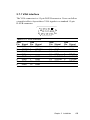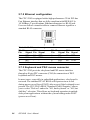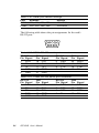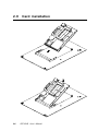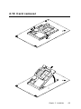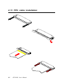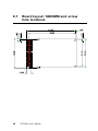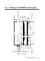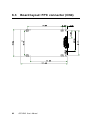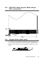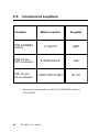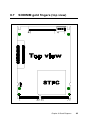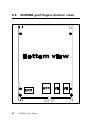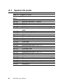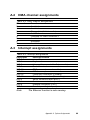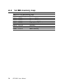
1
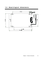
CPC-2245 Series
486 Mini Biscuit PC with VGA/LAN
User’s Manual
Copyright notice
This document is copyrighted, October 1999. All rights are reserved. The original manufacturer reserves the right to make
improvements to the products described in this manual at any time
without notice.
No part of this manual may be reproduced, copied, translated or
transmitted in any form or by any means without the prior written
permission of the original manufacturer. Information provided in
this manual is intended to be accurate and reliable. However, the
original manufacturer assumes no responsibility for its use, nor for
any infringements upon the rights of third parties which may result
from its use.
Acknowledgements
AMI is a trademark of American Megatrends, Inc.
Cyrix is a trademark of Cyrix Corporation.
IBM, PC/AT, PS/2 and VGA are trademarks of International
Business Machines Corporation.
Intel and Pentium are trademarks of Intel Corporation.
Microsoft Windows and MS-DOS are registered trademarks of
Microsoft Corp.
C&T is a trademark of Chips and Technologies, Inc.
All other product names or trademarks are properties of their
respective owners.
Part No. 2006224501
2nd Edition Printed in Taiwan March 2001
Product warranty
Advantech warrants to you, the original purchaser, that each of its
products will be free from defects in materials and workmanship for
one year from the date of purchase.
This warranty does not apply to any products that have been
repaired or altered by persons other than repair personnel authorized by Advantech, or which have been subject to misuse, abuse,
accident or improper installation. Advantech assumes no liability
under the terms of this warranty as a consequence of such events.
Because of Advantech high quality-control standards and rigorous
testing, most of our customers never need to use our repair service.
If an Advantech product is defective, it will be repaired or replaced
at no charge during the warranty period. For out-of-warranty
repairs, you will be billed according to the cost of replacement
materials, service time and freight. Please consult your dealer for
more details. If you think you have a defective product, follow
these steps:
1. Collect all the information about the problem encountered. (For
example, CPU speed, Advantech products used, other hardware
and software used, etc.) Note anything abnormal and list any
on- screen messages you get when the problem occurs.
2. Call your dealer and describe the problem. Please have your
manual, product, and any helpful information readily available.
3. If your product is diagnosed as defective, obtain an RMA
(return merchandize authorization) number from your dealer.
This allows us to process your return more quickly.
4. Carefully pack the defective product, a fully-completed Repair
and Replacement Order Card and a photocopy proof of purchase date (such as your sales receipt) in a shippable container.
A product returned without proof of the purchase date is not
eligible for warranty service.
5. Write the RMA number visibly on the outside of the package
and ship it prepaid to your dealer.
Packing list
Before installing your board, ensure that the following materials
have been received:
• 1 CPC-2245 all-in-one single board computer
• 3 floppy disks (or one CD-ROM) including Ethernet utility
programs, and SVGA utility programs and drivers for Windows
3.1/95/98/NT
• 1 warranty certificate
• This user's manual
If any of these items are missing or damaged, contact your distributor or sales representative immediately.
Technical support and sales assistance
If you have any technical questions about the CPC-2245 or any
other Advantech products, please visit our support website at:
http://support.advantech.com.tw
For more information about Advantech's products and sales
information, please visit:
http://www.advantech.com
Contents
Chapter 1 General Information ................................. 1
1.1
1.2
1.3
Introduction .................................................................. 2
Specifications ............................................................... 3
ISA/IDE/FDD/parallel port (144-pin SODIMM socket) 3
VGA/LAN/serial port/keyboard/mouse (40-pin FPC ......
connector) .................................................................. 4
Mechanical and environmental ....................................... 4
Board layout: dimensions .......................................... 5
Chapter 2 Installation ................................................ 7
2.1
2.2
2.3
2.4
Jumpers and connectors ............................................ 8
Board layout: jumper/connector locations .............. 9
Safety precautions ..................................................... 10
Setting jumpers.......................................................... 11
2.4.1 Clear CMOS (J2) ................................................. 12
2.5 CompactFlash interface (CN2) ................................ 12
2.6 ISA/IDE/floppy drive/parallel port (CN3) .............. 13
2.6.1 ISA bus .................................................................16
2.6.2 IDE interface ........................................................ 20
2.6.3 Floppy drive .......................................................... 22
2.6.4 Parallel port .......................................................... 23
2.7 VGA/LAN/serial ports/keyboard/mouse (CN4) ... 24
2.7.1 VGA interface ...................................................... 25
2.7.2 Ethernet configuration .......................................... 26
2.7.3 Keyboard and PS/2 mouse connector .................. 26
2.7.4 Serial ports ............................................................ 27
2.8 Power supply connector (CN5) ............................... 29
2.9 Card installation ........................................................ 30
2.10 Card removal ............................................................. 31
2.11 FPC cable installation ............................................... 32
Chapter 3 Award BIOS Setup ................................. 33
3.1
3.2
3.3
3.4
3.5
3.6
3.7
3.8
General information .................................................. 34
Starting Award BIOS setup ..................................... 34
Award BIOS main menu ............................................... 34
Standard CMOS features ......................................... 35
Advanced BIOS features ......................................... 36
Virus Warning ................................................................ 36
Quick Power On Self Test ............................................ 37
Boot Sequence .............................................................. 37
Boot Up Floppy Seek .................................................... 37
Boot Up NumLock Status ............................................. 38
Gate A20 Option ........................................................... 38
Typematic Rate Setting ................................................. 38
Typematic Rate (Chars/Sec) ......................................... 38
Typematic Delay (msec) ............................................... 38
Security Option .............................................................. 38
OS Select for DRAM > 64 MB .................................... 39
Video BIOS Shadow ..................................................... 39
C8000-CBFFF Shadow / CC000-CFFFF Shadow ........ 39
Advanced chipset features ...................................... 40
Video Memory Size ....................................................... 40
Integrated peripherals.............................................. 41
Onboard FDC Controller ............................................... 41
Onboard Serial Port 1/2 ................................................. 41
Onboard Parallel Port .................................................... 42
Parallel Port Mode ........................................................ 42
Power management setup ........................................ 43
Power Management ...................................................... 43
Standby mode ................................................................ 44
PnP/PCI configuration setup ................................... 44
Resources Control ......................................................... 44
IRQ resources ............................................................... 45
DMA resources ............................................................ 45
Memory resources ........................................................ 45
3.9
3.10
3.11
3.12
3.13
Load fail-safe defaults ............................................... 45
Load optimized defaults ........................................... 46
Password setting ....................................................... 46
Save & exit setup ...................................................... 46
Exit without saving .................................................... 47
Chapter 4 Software Configuration ......................... 49
4.1
Ethernet software configuration ............................. 50
Chapter 5 PCI Bus Ethernet Interface .................... 51
5.1
5.2
5.3
Introduction ................................................................ 52
Installation of Ethernet driver ................................ 52
5.2.1 Installation for MS-DOS and Windows 3.1 .......... 52
5.2.2 Installation for Windows 95 .................................. 53
5.2.3 Installation for Windows NT ................................ 55
Further information ................................................... 57
Chapter 6 Board Diagrams ..................................... 59
6.1
6.2
6.3
6.4
6.5
6.6
6.7
6.8
Board layout: SODIMM and screw hole
locations ...................................................................... 60
PCB layout: SODIMM mounting side ................... 61
Board layout: FPC connector (CN4) ...................... 62
FPC/FFC cable layout:
(CN4; 40-pin FPC connector) ................................. 63
Height limits (side view) .......................................... 63
Component suppliers ............................................... 64
SODIMM gold fingers (top view) .......................... 65
SODIMM gold fingers (bottom view) .................... 66
Appendix A System Assignments .......................... 67
A.1
A.2
A.3
A.4
System I/O ports ....................................................... 68
DMA channel assignments ...................................... 69
Interrupt assignments .............................................. 69
1st MB memory map ................................................ 70
Figures
Figure
Figure
Figure
Figure
Figure
Figure
Figure
Figure
Figure
2-1: Board layout: jumper/connector locations .............................. 9
2-2: Damping resistor .................................................................. 21
3-1: Main menu ............................................................................ 34
3-2: Standard CMOS setup screen .............................................. 35
3-3: BIOS features setup screen ................................................. 36
3-4: CHIPSET features setup screen .......................................... 40
3-5: Integrated peripherals .......................................................... 41
3-6: Power management setup screen ...................................... 43
3-7: PCI configuration screen ...................................................... 44
Tables
Table 2-1: Jumpers and connectors ......................................................... 8
Table 2-2: Clear CMOS (J2) .................................................................... 12
Table 2-3: ISA/IDE/floppy drive/parallel port connector (CN3) ................ 14
Table 2-4: ISA bus - CN3 cross reference table (ISA pin A) ................... 16
Table 2-5: ISA bus - CN3 cross reference table (ISA bus pin B) ............ 17
Table 2-6: ISA bus - CN3 cross reference table (ISA bus pin C) ............ 18
Table 2-7: ISA bus - CN3 cross reference table (IDE pin D) .................. 19
Table 2-8: IDE hard drive connector ........................................................ 20
Table 2-9: Floppy drive connector ........................................................... 22
Table 2-10: Parallel port connector ......................................................... 23
Table 2-11: FPC connector (CN4) ........................................................... 24
Table 2-12: VGA interface ........................................................................ 25
Table 2-13: Ethernet configuration .......................................................... 26
Table 2-14: PS/2 keyboard connector ..................................................... 27
Table 2-15: PS/2 mouse connector ........................................................ 27
Table 2-16: Serial port default settings ................................................... 28
Table 2-17: COM1 RS-232 serial port connector .................................... 28
Table 2-18: COM2 RS-232 serial port connector .................................... 28
Table 2-19: Power supply connector (CN5) ............................................ 29
Table A-1: System I/O ports ..................................................................... 68
Table A-2: DMA channel assignments .................................................... 69
Table A-3: Interrupt assignments ............................................................ 69
Table A-4: 1st MB memory map .............................................................. 70
CHAPTER
1
General Information
This chapter provides background
information for the CPC-2245.
Sections include:
• Card specifications
• Board layout
1.1
Introduction
Advantech’s new mini biscuit PC, the CPC-2245, is truly an all-in
one 486 processor-based single board computer. It comes equipped
with 32 MB DRAM on board, an SVGA interface which supports
CRT monitors with up to 4 MB display memory, a 10/100Base-T
Ethernet interface, and a CompactFlash solid state disk socket. In
addition, it is equipped with two RS-232 serial ports, one bidirectional printer port which supports SPP, ECP and EPP modes, an IDE
HDD interface, a floppy disk controller, as well as one ISA interface
for functional expansion. With its industrial grade reliability, the
CPC-2245 can operate continuously at temperatures up to 60º C
(140º F). This compact unit offers all these functions within the
space of a 2.5" hard disk drive (68 x 100 mm). All these numerous
features provide an ideal price/performance solution for commercial
and industrial applications where stability and reliability are
essential.
The CPC-2245 mini biscuit PC’s power can be supplied through a
SODIMM socket or an on-board power connector. Thus, the
CPC-2245 can be embedded into the user’s system board, or used
as a single board application. The ISA bus, HDD, FDD and parallel
interface are connected to the user’s system board via a SODIMM
socket. This form factor has the benefits of easy maintenance. A
damaged card can be replaced within 30 seconds. Furthermore, the
mini biscuit PC is easily upgraded from 486 to Pentium® without the
need to change the user’s system board.
The CPC-2245 provides many useful functions in a tiny card. It
reserves a small PCI connector for other extension modules, such
as the CPC-2520 VGA/LCD module. It provides more flexible
functions to satisfy all users' different application requirements.
The CPC-2245 is small-sized, highly integrated, easy to maintain,
easy to upgrade, and easy to install. These features make it ideal for
applications such as small industrial controllers, panel PCs,
security systems, Internet gateways, instruments, medical
equipment, building automation, and so on.
2
CPC-2245 User's Manual
1.2
Specifications
• CPU: STPC Client, 66 MHz
• On-card cache: 8 KB
• BIOS: 256 KB Flash BIOS
• Chipset: STPC Client
• Super I/O chipset: Winbond W83977F
• RAM memory: 32 MB EDO RAM on board
• Solid state disk: Supports one CompactFlash card as an
emulated HDD
• Watchdog timer: 1.6 sec. intervals
ISA/IDE/FDD/parallel port (144-pin SODIMM
socket)
• I/O expansion: 16-bit AT-bus
• Enhanced IDE hard disk drive interface: Supports up to two
hard disk drives. BIOS auto-detect
• Floppy disk drive interface/multi-mode parallel port: FDD
interface and parallel port share the same connector. The FDD
and/or parallel port can be switched in BIOS setup
- FDD interface supports up to two floppy disk drives, 5.25"
(360 KB and 1.2 MB) and/or 3.5" (720 KB, 1.44 MB and 2.88
MB)
- Parallel supports SPP, ECP and EPP
Chapter 1 General Information
3
VGA/LAN/serial port/keyboard/mouse (40-pin FPC
connector)
• VGA with 64-bit windows accelerator
- Display memory: 4 MB share memory architecture (UMA
structure)
- Display resolution: 1280 x 1024 @ 64 K colors, 1024 x 768 @
16 M colors
- Automatically disables internal VGA if an external add-in VGA
is plugged into the system
• 10/100Base-T Ethernet interface
- Chipset: RTL-8139A PCI local bus Ethernet controller
- Ethernet interface: IEEE 802.3U compatible 100/10Base-T
interface
• Serial ports: Two RS-232 serial ports
• Keyboard and PS/2 mouse: Supports standard PC/AT keyboard
and PS/2 mouse
• Power connector: 4-pin mini power connector
Mechanical and environmental
• Power supply voltage: +5 V (4.75 ~ 5.25 V)
• Max. power requirements: +5 V @ 1.6 A
• Operating temperature: 0 ~ 60° C (32 ~ 140° F)
• Board size: 68 x 100 mm
• Weight: 0.05 kg (0.11 lb)
4
CPC-2245 User's Manual
1.3
Board layout: dimensions
Chapter 1 General Information
5
6
CPC-2245 User's Manual
CHAPTER
2
Installation
This chapter explains the setup procedures of CPC-2245 hardware, including
instructions on setting jumpers and
connecting peripherals, switches and
indicators. Be sure to read all safety
precautions before you begin the installation procedure.
2.1
Jumpers and connectors
On-board connectors link to external devices such as hard disk
drives, keyboards, floppy drives, and so on. In addition, the board
has jumpers for configuring your board for specific applications.
The table below lists the function of each of the board’s jumpers
and connectors. Later sections in this chapter give detailed
information on each jumper setting, and instructions for connecting
external devices to your card.
Table 2-1: Jumpers and connectors
Name
CN1
CN2
CN3
CN4
CN5
J2
J3
8
Function
PCI connector
CompactFlash socket
SODIMM gold finger (ISA/HDD/FDD/parallel/power)
I/O connector (LAN/VGA/RS-232/KB/mouse)
Power connector
Clear CMOS
Fan connector (reserved)
CPC-2245 User's Manual
2.2
Board layout: jumper/connector
locations
Figure 2-1: Board layout: jumper/connector locations
Chapter 2 Installation
9
2.3
10
Safety precautions
Warning!
Always completely disconnect the power cord from
your chassis whenever you are working on it. Do
not --make connections while the power is on
because sensitive electronic components can be
damaged by the sudden rush of power. Only
experienced electronics personnel should open
the PC chassis.
Caution!
Always ground yourself to remove any static
charge before touching the CPU card. Modern
electronic devices are very sensitive to static
electric charges. Use a grounding wrist strap at all
times. Place all electronic components on a
static-dissipative surface or in a static-shielded
bag when they are not in the chassis.
CPC-2245 User's Manual
2.4
Setting jumpers
You may configure your card to match the needs of your application by setting jumpers. A jumper is the simplest kind of electrical
switch. It consists of two metal pins and a small metal clip (often
protected by a plastic cover) that slides over the pins to connect
them. To "close" a jumper, you connect the pins with the clip. To
"open” a jumper, you remove the clip. Sometimes a jumper will have
three pins, labeled 1, 2 and 3. In this case you would connect either
pins 1 and 2, or 2 and 3.
1
Open
Closed
2
3
Closed 2-3
The jumper settings are schematically depicted in this manual as
follows:
1 2 3
Open
Closed
Closed 2-3
A pair of needle-nose pliers may be helpful when working with
jumpers.
If you have any doubts about the best hardware configuration for
your application, contact your local distributor or sales representative before you make any changes.
Generally, you simply need a standard cable to make most connections.
Chapter 2 Installation
11
2.4.1 Clear CMOS (J2)
This jumper is used to erase CMOS data and reset system BIOS
information.
The procedure for clearing CMOS is:
1. Turn off the system.
2. Short pin 2 and pin 3.
3. Turn on the system. The CMOS is now cleared.
4. Turn off the system. Short pin 1 and pin 2.
5. Turn on the system. The BIOS is now reset to its default
setting.
Table 2-2: Clear CMOS (J2)
Function
Protect*
Clear CMOS
1-2
Closed
Open
2-3
Open
Closed
* default setting
2.5
CompactFlash interface (CN2)
This socket accepts an IDE-compatible CompactFlash memory
card.
The CompactFlash interface uses a primary IDE channel, which
should be set as the master channel.
12
CPC-2245 User's Manual
2.6
ISA/IDE/floppy drive/parallel port
(CN3)
The CPC-2245 provides a +5 V 16-bit ISA bus, one IDE channel
(support two IDE devices), one parallel interface and one floppy
interface (support two floppy drives). All these are provided via a
144-pin SODIMM gold finger (CN3), which can be plugged into a
DODIMM socket on the user's system board. Users can choose
suitable positions on their system board for their HDD, FDD or
parallel connectors.
The floppy interface and parallel interface share the same pin
assignment, so they cannot be used simultaneously. Users can
select either an FDD or parallel port, by referring to their BIOS
setup manual.
Chapter 2 Installation
13
Table 2-3: ISA/IDE/floppy drive/parallel port connector (CN3)
Pin
1
2
3
4
5
6
7
8
9
10
11
12
13
14
15
16
17
18
19
20
21
22
23
24
25
26
27
28
29
30
31
32
33
34
35
14
Signal
+5 V
ZW
SA18
SA19
+5 V
+5 V
+5 V
TC
GND
GND
GND
GND
GND
GND
GND
GND
IRQ6
IRQ5
IRQ4
SA10
SA9
SA14
SA17
SA12
IRQ12
SYSCLK
DRQ3
OSC (14 MHz)
DRQ1
DRQ0
HDACK
HDIOW
LA17
LA19
LA22
CPC-2245 User's Manual
Bus
POWER
ISA
ISA
ISA
POWER
POWER
POWER
ISA
POWER
POWER
POWER
POWER
POWER
POWER
POWER
POWER
ISA
ISA
ISA
ISA
ISA
ISA
ISA
ISA
ISA
ISA
ISA
ISA
ISA
ISA
IDE
IDE
ISA
ISA
ISA
Pin
73
74
75
76
77
78
79
80
81
82
83
84
85
86
87
88
89
90
91
92
93
94
95
96
97
98
99
100
101
102
103
104
105
106
107
Signal
+5 V
RESET
RSTDRV
IRQ3
GND
DACK7
DACK6
DACK5
DACK3
DACK2
DACK1
DACK0
HDCS0
HDCS1
GND
IRQ7
IRQ9
IRQ10
IRQ11
SA11
SA8
SA13
SA16
SA15
IRQ15
IRQ14
DRQ2
DRQ5
DRQ6
DRQ7
HDDRQ
HDIRQ
HDIOR
LA20
LA18
Bus
POWER
IDE
ISA
ISA
POWER
ISA
ISA
ISA
ISA
ISA
ISA
ISA
IDE
IDE
POWER
ISA
ISA
ISA
ISA
ISA
ISA
ISA
ISA
ISA
ISA
ISA
ISA
ISA
ISA
ISA
IDE
IDE
IDE
ISA
ISA
36
37
38
39
40
41
42
43
44
45
46
47
48
49
50
51
52
53
54
55
56
57
58
59
60
61
62
63
64
65
66
67
68
69
70
71
72
SA0
LA23
SA2
SA6
HDD0
HDD8
HDD2
HDD1
HDD6
HDD10
HDD7
HDD14
HDD13
SD8
SD10
SD11
SD9
SD14
SD13
SD12
BALE
SD15
SMEMR
SBHE
MEMR
IOCS16
IOCHCK
REFRESH
ACK
PE
PD6
PD4
PD2
PD0
STROBE
INIT
SLCTIN
ISA
ISA
ISA
ISA
IDE
IDE
IDE
IDE
IDE
IDE
IDE
IDE
IDE
ISA
ISA
ISA
ISA
ISA
ISA
ISA
ISA
ISA
ISA
ISA
ISA
ISA
ISA
ISA
PRT
PRT
PRT
PRT
PRT
PRT
PRT
PRT
PRT
108
109
110
111
112
113
114
115
116
117
118
119
120
121
122
123
124
125
126
127
128
129
130
131
132
133
134
135
136
137
138
139
140
141
142
143
144
LA21
SA1
SA4
SA3
SA7
SA5
HDD11
HDD3
HDD5
HDD4
HDD9
HDD15
HDD12
SD0
SD2
SD3
SD4
SD1
SD6
SD7
SD5
IOCHRDY
MEMW
IOR
MASTER
SMEMW
MEMCS16
IOW
AEN
BUSY
PD5
PD3
PD1
AUTOFD
ERR
PD7
SLCT
ISA
ISA
ISA
ISA
ISA
ISA
IDE
IDE
IDE
IDE
IDE
IDE
IDE
ISA
ISA
ISA
ISA
ISA
ISA
ISA
ISA
ISA
ISA
ISA
ISA
ISA
ISA
ISA
ISA
PRT
PRT
PRT
PRT
PRT
PRT
PRT
PRT
Chapter 2 Installation
15
2.6.1 ISA bus
Table 2-4: ISA bus - CN3 cross reference table (ISA pin A)
ISA bus
Pin
A1
A2
A3
A4
A5
A6
A7
A8
A9
A10
A11
A12
A13
A14
A15
A16
A17
A18
A19
A20
A21
A22
A23
A24
A25
A26
A27
A28
A29
A30
A31
16
Signal
I/O CHCK
SD7
SD6
SD5
SD4
SD3
SD2
SD1
SD0
I/OCHRDY
AEN
SA19
SA18
SA17
SA16
SA15
SA14
SA13
SA12
SA11
SA10
SA9
SA8
SA7
SA6
SA5
SA4
SA3
SA2
SA1
SA0
CPC-2245 User's Manual
CN3
Pin
62
127
126
128
124
123
122
125
121
129
136
4
3
23
95
96
22
94
24
92
20
21
93
112
39
113
110
111
38
109
36
Signal
IOCHCK
SD7
SD6
SD5
SD4
SD3
SD2
SD1
SD0
IOCHRDY
AEN
SA19
SA18
SA17
SA16
SA15
SA14
SA13
SA12
SA11
SA10
SA9
SA8
SA7
SA6
SA5
SA4
SA3
SA2
SA1
SA0
Table 2-5: ISA bus - CN3 cross reference table (ISA bus pin B)
ISA bus
Pin
B1
B2
B3
B4
B5
B6
B7
B8
B9
B10
B11
B12
B13
B14
B15
B16
B17
B18
B19
B20
B21
B22
B23
B24
B25
B26
B27
B28
B29
B30
B31
Signal
GND
RSTDRV
+5 V
IRQ9
-5 V
DRQ2
-12 V
0 WS
+12 V
GND
SMEMW
SMEMR
IOW
IOR
DACK3
DRQ3
DACK1
DRQ1
REFRESH
CLK
IRQ7
IRQ6
IRQ5
IRQ4
IRQ3
DACK2
T/C
BALE
+5 V
OSC
GND
CN3
Pin
9
75
1
89
99
2
10
133
58
135
131
81
27
83
29
63
26
88
17
18
19
76
82
8
56
73
28
11
Signal
GND
RSTDRV
+5 V
IRQ9
DRQ2
ZW
GND
SMEMW
SMEMR
IOW
IOR
DACK3
DRQ3
DACK1
DRQ1
REFRESH
SYSCLK
IRQ7
IRQ6
IRQ5
IRQ4
IRQ3
DACK2
TC
BALE
+5 V
OSC (14 MHz)
GND
Chapter 2 Installation
17
Table 2-6: ISA bus - CN3 cross reference table (ISA bus pin C)
ISA bus
Pin
C1
C2
C3
C4
C5
C6
C7
C8
C9
C10
C11
C12
C13
C14
C15
C16
C17
C18
18
Signal
SBHE
LA23
LA22
LA21
LA20
LA19
LA18
LA17
MEMR
MEMW
SD8
SD9
SD10
SD11
SD12
SD13
SD14
SD15
CPC-2245 User's Manual
CN3
Pin
59
37
35
108
106
34
107
33
60
130
49
52
50
51
55
54
53
57
Signal
SBHE
LA23
LA22
LA21
LA20
LA19
LA18
LA17
MEMR
MEMW
SD8
SD9
SD10
SD11
SD12
SD13
SD14
SD15
Table 2-7: ISA bus - CN3 cross reference table (IDE pin D)
ISA bus
Pin
D1
D2
D3
D4
D5
D6
D7
D8
D9
D10
D11
D12
D13
D14
D15
D16
D17
D18
Signal
MEMCS16
I/OCS16
IRQ10
IRQ11
IRQ12
IRQ15
IRQ14
DACK0
DRQ0
DACK5
DRQ5
DACK6
DRQ6
DACK7
DRQ7
+5 V
MASTER
GND
CN3
Pin
134
61
90
91
25
97
98
84
30
80
100
79
101
78
102
5
132
12
Signal
MEMCS16
IOCS16
IRQ10
IRQ11
IRQ12
IRQ15
IRQ14
DACK0
DRQ0
DACK5
DRQ5
DACK6
DRQ6
DACK7
DRQ7
+5 V
MASTER
GND
Chapter 2 Installation
19
2.6.2 IDE interface
Users can attach two IDE devices to the IDE channel, one drive
must be set as the master and another as the slave. You may do this
by setting the jumpers on the drives. Refer to the documentation
that came with your drive for more information.
A jumper diagram usually appears on the top side of a hard disk
drive.
IDE hard drive connector
Table 2-8: IDE hard drive connector
IDE connector
Pin Signal
CN3
Pin Signal
IDE connector
Pin Signal
CN3
Pin Signal
1
3
5
7
9
11
13
15
17
19
21
23
25
27
74
46
44
116
117
115
42
43
40
14
103
32
105
129
RESET
HDD7
HDD6
HDD5
HDD4
HDD3
HDD2
HDD1
HDD0
GND
HDDRQ
HDIOW
HDIOR
IOCHRDY
2
4
6
8
10
12
14
16
18
20
22
24
26
28
GND
DATA 8 (*2)
DATA 9 (*2)
DATA 10 (*2)
DATA 11 (*2)
DATA 12 (*2)
DATA 13 (*2)
DATA 14 (*2)
DATA 15 (*2)
N/C
GND
GND
GND
GND (*1)
13
41
118
45
114
120
48
47
119
14
14
15
15
GND
HDD8
HDD9
HDD10
HDD11
HDD12
HDD13
HDD14
HDD15
GND
GND
GND
GND
31
104
107
33
85
HDACK
HDIRQ
LA18
LA17
HDCS0
30
32
34
36
38
16
86
GND
HDCS1
6
+5 V
40
42
GND
N/C
N/C
ADDR 2
HARD DISK
SELECT 1 (*2)
GND
VCC
16
6
+5 V
16
GND
44
N/C
-
-
39
41
IDE RESET
DATA 7 (*2)
DATA 6 (*2)
DATA 5 (*2)
DATA 4 (*2)
DATA 3 (*2)
DATA 2 (*2)
DATA 1 (*2)
DATA 0 (*2)
SIGNAL GND
DMA REQUEST
IO WRITE (*2)
IO READ (*2)
IO CHANNEL
READY
HDACK
IRQ
ADDR 1
ADDR 0
HARD DISK
SELECT 0 (*2)
IDE ACTIVE
VCC
43
GND
29
31
33
35
37
20
CPC-2245 User's Manual
Note *1:
IDE pin 28 must pull 470 ohms resistor to GND.
Note *2:
33 ohms damping resistors is recommended to
connect near IDE connector. Please refer to Fig.
2-2 below.
Note *3:
We do not recommend connection to the following
IDE HDD models of Seagate: ST 31276A, ST
31720A, ST 32531A, ST 33240A or ST 34340A
Figure 2-2: Damping resistor
Chapter 2 Installation
21
2.6.3 Floppy drive
Users can attach up to two floppy disk drives to the CPC-2245 via a
SODIMM socket. The CPC-2245 supports any combination of 5.25"
(360 KB / 1.2 MB) and/or 3.5" (720 KB / 1.44/2.88 MB) drives.
The following table lists the pin assignments for the floppy disk
connector:
Table 2-9: Floppy drive connector
FDD connctr.
Pin Signal
1
GND
3
GND
5
GND
7
GND
9
GND
11 GND
13 GND
15 GND
17 GND
19 GND
21 GND
23 GND
25 GND
27 GND
29 GND
31 GND
33 GND
22
CN3
Pin Signal
9
GND
9
GND
10 GND
10 GND
11 GND
11 GND
12 GND
12 GND
13 GND
13 GND
14 GND
14 GND
15 GND
15 GND
16 GND
16 GND
9
GND
CPC-2245 User's Manual
FDD connector
Pin Signal
2
High density
4
N/C
6
N/C
8
Index
10 Motor enable A
12 Driver select B
14 Driver select A
16 Motor enable B
18 Direction
20 Step pulse
22 Write data
24 Write enable
26 Track 0
28 Write protect
30 Read data
32 Select head
34 Disk change
CN3
Pin Signal
141 AUTOFD
69
66
64
143
137
71
72
65
144
140
68
139
142
67
PD0
PD6
ACK
PD7
BUSY
INIT
SLCTIN
PE
SLCT
PD1
PD2
PD3
ERR
PD4
2.6.4 Parallel port
The parallel port is normally used to connect the CPU card to a
printer through a DB25 connector. The CPC-2245 includes an onboard parallel port, accessed through a SO. DIMM golden finger.
The parallel port is designated as LPT1 and can be disabled or
changed to LPT2 or LPT3 in the BIOS setup manual.
Table 2-10: Parallel port connector
Printer port
Pin Signal
1
/STROBE
2
DO
3
D1
4
D2
5
D3
6
D4
7
D5
8
D6
9
D7
10 \ACK
11 BUSY
12 PE
13 SLCT
CN3
Pin
70
69
140
68
139
67
138
66
143
64
137
65
144
Signal
STROBE
PD0
PD1
PD2
PD3
PD4
PD5
PD6
PD7
ACK
BUSY
PE
SLCT
Printer port
Pin Signal
14 \AUTOFD
15 ERR
16 \INIT
17 \SLCTINI
18 GND
19 GND
20 GND
21 GND
22 GND
23 GND
24 GND
25 GND
CN3
Pin
141
142
71
72
9
9
10
10
11
11
12
12
Signal
AUTOFD
ERR
INIT
SLCTIN
GND
GND
GND
GND
GND
GND
GND
GND
Chapter 2 Installation
23
2.7
VGA/LAN/serial ports/keyboard/
mouse (CN4)
The CPC-2245 provides a VGA interface, a 10/100 Base-T Ethernet,
two RS-232 serial ports, one keyboard and one PS2 mouse through
a 40-pins FPC connector (CN4). User can design their FPC cable for
connecting CPC-2245's FPC connector to user's system board. User
can choose suitable position to layout VGA, LAN, COM port,
Keyboard and mouse connector on user's system board.
Table 2-11: FPC connector (CN4)
Pin
1
2
3
4
5
6
7
8
9
10
11
12
13
14
15
16
17
18
19
20
24
Signal
GND
KBVCC
EXT RESET
DDC1
DDC0
V SYNC
H SYNC
BLUE
GREEN
RED
KBVCC
GND
RI1
CTS1
RTS1
DTR1
TX1
CD1
RX1
DSR1
CPC-2245 User's Manual
Pin
21
22
23
24
25
26
27
28
29
30
31
32
33
34
35
36
37
38
39
40
Signal
DSR2
RX2
CD2
TX2
RI2
CTS2
RTS2
DTR2
KBVCC
MSDT
KBDT
KBCK
MSCK
GND
TPTTPT+
GND
TPRTPR+
GND
2.7.1 VGA interface
The VGA connector is a 15-pin D-SUB connector. Users can follow
a transfer table to layout these VGA signals to a standard 15-pin
D-SUB connector.
5
1
10
6
15
11
Table 2-12: VGA interface
VGA
Pin
1
2
3
4
5
6
7
8
Signal
RED
GREEN
BLUE
N/C
GND
GND
GND
GND
CN4
Pin
10
9
8
1
1
12
12
Signal
RED
GREEN
BLUE
GND
GND
GND
GND
VGA
Pin
9
10
11
12
13
14
15
Signal
Vcc
GND
N/C
SDT
H-SYNC
V-SYNC
SCK
CN4
Pin
2
1
5
7
6
4
Signal
KBVCC
GND
DDC0
H SYNC
V SYNC
DDC1
Chapter 2 Installation
25
2.7.2 Ethernet configuration
The CPC-2245 is equipped with a high performance 32-bit PCI-bus
Fast Ethernet interface that are fully compliant with IEEE 802.3u
10/100Base-T specifications. Ethernet connector is a RJ-45 jack.
User can follow a transfer table to connect Ethernet signals to a
standard RJ-45 connector.
Table 2-13: Ethernet configuration
RJ-45
Pin
1
3
5
7
Signal
TD+
RD+
NC
NC
CN4
Pin
36
39
-
Signal
TPT+
TPR+
-
RJ-45
Pin
2
4
6
8
Signal
TD NC
RDNC
CN4
Pin
35
38
-
Signal
TPTTPR-
2.7.3 Keyboard and PS/2 mouse connector
The CPC-2245 provides a keyboard and PS2 mouse interface
through a 40-pin FPC connector (CN4) for connection of PS/2
keyboard and PS/2 mouse.
In most cases, especially in embedded applications, a keyboard is
not used. The standard PC/AT BIOS will report an error or fail
during power-on self-test (POST) after a reset if the keyboard is not
present. The CPC-2245's BIOS "Standard CMOS Features" allows
you to select "Halt on" under the "All, but keyboard" or "All, but
disk/key" selection. This allows no-keyboard operation in embedded system applications without the system halting under POST
(power on self test).
26
CPC-2245 User's Manual
Table 2-14: PS/2 keyboard connector
PS/2 Keyboard
Pin Signal
1
KB_Data
2
NC
3
GND
CN4
Pin Signal
31 KBDT
34 GND
PS/2 Keyboard
Pin Signal
4
Vcc
5
KBCLK
6
NC
CN4
Pin
29
32
-
Signal
KBVCC
KBCK
-
CN4
Pin
29
33
-
Signal
KBVCC
MSCK
-
Table 2-15: PS/2 mouse connector
PS/2 Mouse
Pin Signal
1
MDATA
2
NC
3
GND
CN4
Pin Signal
30 MSDT
34 GND
PS/2 Mouse
Pin Signal
4
Vcc
5
MCLK
6
NC
2.7.4 Serial ports
The CPC-2245 offers two serial ports: COM1 and COM2, both in
RS- 232. These ports let you connect to serial devices (a mouse,
printers, etc.) or a communication network.
You can select the address for each port (For example, 3F8H
[COM1], 2F8H [COM2]) or disable it, using the BIOS Advanced
Setup program. Different devices implement the RS-232 standard in
different ways. If you are having problems with a serial device, be
sure to check the pin assignments for the connector.
The IRQ and address range for both ports are fixed. However, if
you wish to disable the port or change these parameters later, you
can do this in the system BIOS setup. The table below shows the
settings for the CPC-2245 board's ports:
Chapter 2 Installation
27
Table 2-16: Serial port default settings
Port
COM1
COM2
Address
3F8, 2F8, 3E8, 2E8
3F8, 2F8, 3E8, 2E8
Default
3F8/IRQ4
2F8/IRQ3
The following table shows the pin assignments for the card's
RS-232 port:
5
1
6
9
Table 2-17: COM1 RS-232 serial port connector
RS-232
Pin Signal
1
DCD
2
RX
3
TX
4
DTR
5
GND
CN4
Pin
18
19
17
16
37
Signal
CD1
RX1
TX1
DTR1
GND
RS-232
Pin Signal
6
DSR
7
RTS
8
CTS
9
RI
CN4
Pin
20
15
14
13
Signal
DSR1
RTS1
CTS1
RI1
Table 2-18: COM2 RS-232 serial port connector
RS-232
Pin Signal
1
DCD
2
RX
3
TX
4
DTR
5
GND
28
CN4
Pin
23
22
24
28
40
Signal
CD2
RX2
TX2
DTR2
GND
CPC-2245 User's Manual
RS-232
Pin Signal
6
DSR
7
RTS
8
CTS
9
RI
CN4
Pin
21
27
26
25
Signal
DSR2
RTS2
CTS2
RI2
2.8
Power supply connector (CN5)
In single board computer without carrier applications, user may
connect a power directly to the CPC-2245 board through CN5. See
the following table for its pin assignments:
Table 2-19: Power supply connector (CN5)
Pin
1
2
3
4
Function
+5 V
GND
GND
+5 V
Chapter 2 Installation
29
2.9
30
Card installation
CPC-2245 User's Manual
2.10 Card removal
Chapter 2 Installation
31
2.11 FPC cable installation
32
CPC-2245 User's Manual
CHAPTER
3
Award BIOS Setup
This chapter describes how to set the
BIOS configuration data.
3.1
General information
Award BIOS ROM has a built-in setup program that allows users
to modify the basic system configuration. This type of information
is stored in battery-backed RAM so that it retains the setup
information when the power is turned off.
3.2
Starting Award BIOS setup
As POST executes, the following appears:
Hit <DEL> if you want to run SETUP
Press <DEL> to run AWARDBIOS setup.
Award BIOS main menu
The Award BIOS setup screen appears as follows:
Figure 3-1: Main menu
34
CPC-2245 User's Manual
3.3
Standard CMOS features
Choose the "Standard CMOS Features" option from the main
menu, and the screen below will be displayed. This standard setup
menu allows users to configure system components such as date,
time, hard disk drive, floppy drive, display, and memory.
Figure 3-2: Standard CMOS setup screen
Chapter 3 Award BIOS Setup
35
3.4
Advanced BIOS features
The screen below appears when choosing the "Advanced BIOS
Features " item from the main menu. It allows the user to configure the CPC-2245 according to his particular requirements. Below
are some major items that are provided in the Advanced BIOS
FEATURES setup screen.
A quick booting function is provided for your convenience.
Simply enable the Quick Power On Self Test item to save yourself
valuable time.
Figure 3-3: BIOS features setup screen
Virus Warning
While the system is booting up, and after boot-up, any attempt to
write to the boot sector or partition table of the hard disk drive will
halt the system. In this case, a warning message will be displayed.
You can run the anti-virus program to locate the problem.
If Virus Warning is disabled, no warning message will appear if
anything attempts to access the boot sector or hard disk partition.
36
CPC-2245 User's Manual
Quick Power On Self Test
This option speeds up the Power-On Self Test (POST) conducted
as soon as the computer is turned on. When enabled, BIOS
shortens or skips some of the items during the test. When disabled,
the computer conducts normal POST procedures.
Boot Sequence
This function determines the sequence in which the computer will
search the drives for the disk operating system (i.e. DOS). The
user can define boot sequences from following devices:
Floppy
HDD-0
SCSI
CDROM
HDD-1
HDD-2
HDD-3
Boot Up Floppy Seek
During POST, BIOS will determine if the floppy disk drive
installed is 40 or 80 tracks. A 360 KB type drive is 40 tracks;
while 720 KB, 1.2 MB, and 1.44 MB type drives are all 80 tracks.
Enabled BIOS searches the floppy drive to determine if it is 40 or
80 tracks. Note that BIOS cannot differentiate 720 KB, 1.2 MB,
and 1.44 MB type drives as they are all 80 tracks.
Disabled BIOS will not search for the floppy drive type by track
number. Note that there will not be any warning message if the
drive installed is 360 KB.
Chapter 3 Award BIOS Setup
37
Boot Up NumLock Status
The default is On.
On Keypad boots up to number keys.
Off Keypad boots up to arrow keys.
Gate A20 Option
Normal The A20 signal is controlled by the keyboard controller or
chipset hardware.
Fast (Default) The A20 signal is controlled by Port 92 or the
chipset specific method.
Typematic Rate Setting
The typematic rate determines the characters per second accepted
by the computer. The Typematic Rate setting enables or disables
the typematic rate.
Typematic Rate (Chars/Sec)
BIOS fix the following input values (characters/second) for
typematic rate: 6.
Typematic Delay (msec)
Typematic delay is the time interval between the appearance of the
first and second characters, when holding down a key. The input
value is: 250 (msec).
Security Option
This setting determines whether the system will boot up if the
password is denied. Access to Setup is, however, always limited.
System
The system will not boot, and access to Setup
will be denied if the correct password is not entered at the prompt.
Setup
The system will boot, but access to Setup will
be denied if the correct password is not entered at the prompt.
38
CPC-2245 User's Manual
OS Select for DRAM > 64 MB
This setting is under the OS/2 system.
Video BIOS Shadow
This determines whether video BIOS will be copied to RAM,
which is optional according to the chipset design. When enabled,
Video BIOS
Shadow increases the video speed.
C8000-CBFFF Shadow / CC000-CFFFF Shadow
These determine whether optional ROM will be copied to RAM in
blocks of 16 KB.
Enabled
Optional shadow is enabled.
Disabled
Optional shadow is disabled.
Chapter 3 Award BIOS Setup
39
3.5
Advanced chipset features
By choosing the "Advanced CHIPSET FEATURES" option from
the Main menu, the screen below will be displayed.
This sample screen contains the manufacturer default values for
the CPC-2245.
This section allows you to configure the system based on the
specific features of the installed chipset. This chipset manages bus
speeds and access to system memory resources, such as DRAM
and the external cache. It also coordinates communications
between the conventional ISA bus and the PCI bus. It must be
stated that these items should never need to be altered. The default
settings have been chosen, because they provide the best operating
conditions for your system.
Video Memory Size
The CPC-2245 adopts VGA share memory structure. Video
memory size can be selected from 512 KB to 4096 KB. Onboard
VGA video memory size should be zero, in order to release
memory when the onboard VGA function is not used. Video
memory size will be unchangeable and released automatically
when the CPC-2520 LCD module is plugged into the CPC-2245.
Figure 3-4: CHIPSET features setup screen
40
CPC-2245 User's Manual
3.6
Integrated peripherals
Figure 3-5: Integrated peripherals
Onboard FDC Controller
This option enables the floppy drive controller on the CPC-2245.
The settings are Enabled, or Disabled.
Onboard Serial Port 1/2
This option enables serial port 1/2 on the board and specifies the
base I/O port address for serial port 1~2.
The settings are Disabled, 3F8h/IRQ4, 3E8h/IRQ4, 2E8h/IRQ3,
and 2F8h/IRQ3.
Chapter 3 Award BIOS Setup
41
Onboard Parallel Port
This option enables the parallel port on the CPC-2245 and
specifies the parallel port's base I/O address. The settings are
Disabled, 378/IRQ7, 3BC/IRQ7 and FDD. The default setting is
378/IRQ7.
The CPC-2245's floppy interface and parallel port share the same
pin assignment. When "On board Parallel port" is setting to FDD,
floppy drive will be enabled and printer port will be disabled. If
"On board Parallel port" is setting to either Disabled, 378/IRQ7 or
3BC/IRQ7, printer port will be enable but floppy drive will be
disable.
Parallel Port Mode
This option specifies the parallel port mode. The settings are SPP,
EPP, ECP and EPP+ECP.
Setting
Description
SPP
The normal parallel port mode is used.
EPP
The parallel port can be used with devices that
adhere to the Enhanced Parallel Port (EPP) specification.
EPP
uses the existing parallel port signals to provide
asymmetric bidirectional data transfer driven by the host device.
ECP
The parallel port can be used with devices that
adhere to the Extended Capabilities Port (ECP) specification. ECP
uses the DMA protocol to achieve transfer rates of approximately
2.5 Mbs. ECP provides symmetric bidirectional communications.
42
CPC-2245 User's Manual
3.7
Power management setup
The power management setup controls the CPU card's "green"
features. The following screen shows the manufacturer defaults.
Figure 3-6: Power management setup screen
Power Management
Power management lets you set up your computer to save electricity when it is not actively in use by putting the system into
progressively greater power saving modes. There are two selections for Power Management (Mode):
Disabled Turns off PM
Enabled Maximized power saving by activating maximum
power saving settings after one minute of system inactivity.
When PM is set to Disabled, some items which are predefined will
become unmodifiable.
Chapter 3 Award BIOS Setup
43
Standby mode
This sets the period of system inactivity after which the system
goes into Standby mode, the intermediate power saving state.
The settings range from 2 minutes to 16 minutes and can be set
manually when power management is Enable. The default setting
is Disabled. When the system goes into power saving mode, power
management will skip to the next mode in the sequence if this is
disabled.
3.8
PnP/PCI configuration setup
Figure 3-7: PCI configuration screen
Resources Control
When Resources Controlled by Auto(ESCD), BIOS can automatically configure all the boot and plug and play compatible devices.
IRQ, DMA and Memory resources will become unmodifiable.
When Resources Controlled by Manual, IRQ, DMA and Memory
resource can be set up manually.
44
CPC-2245 User's Manual
IRQ resources
These fields indicate whether or not the displayed IRQ for each
field is being used by a legacy (non-PnP card). Two options are
available: PCI/ISA PnP or Legacy. The first option, the default
setting, indicates that the displayed IRQ is not used to determine if
an ISA card is using that IRQ. If you install a legacy ISA card that
requires a unique IRQ, you must set the field for that IRQ to
"Legacy". Say for example that you install a legacy ISA card that
requires IRQ10. You must then set "IRQ10" assigned to "Legacy".
DMA resources
These fields indicate whether or not the displayed DMA for each
field is being used by a legacy (non-PnP card). Two options are
available: PCI/ISA PnP or Legacy. The first option, the default
setting, indicates that the displayed IRQ is not used to determine if
an ISA card is using that IRQ. If you install a legacy ISA card that
requires a unique DMA, you must set the field for that IRQ to
"Legacy".
Memory resources
Memory length can be reserved as 8 KB, 16 KB, 32 KB or 64 KB
and its address can be selected from C8000 to DC000. Reserved
memory address will not be modified when "Reserved Memory
Base" is N/A.
3.9
Load fail-safe defaults
Load Fail-safe Defaults indicates the most appropriate values for
the system parameters for stability. These default values are loaded
automatically if the stored record created by the setup program
becomes corrupted (and therefore unusable).
Chapter 3 Award BIOS Setup
45
3.10 Load optimized defaults
"Load Optimized Defaults" loads the values required by the
system for maximum performance.
3.11 Password setting
To change the password:
1. Choose the "SET PASSWORD" option from the main menu
and press <Enter>.
The screen will display the following message:
Enter Password:
Press <Enter>.
2. If the CMOS is good or if this option has been used to change
the default password, the user is asked for the password stored
in the CMOS. The screen will display the following message:
Confirm Password:
Enter the current password and press <Enter>.
3. After pressing <Enter> (ROM password) or the current
password (user-defined), you can change the password stored
in the CMOS.
The password must be no longer than eight (8) characters.
Remember, to enable the password seeting feature, you must first
select either SETUP or SYSTEM in "Security Option" item of
"Advanced BIOS features".
3.12 Save & exit setup
If you select this and press <Enter>, the values entered in the setup
utilities will be recorded in the CMOS memory of the chipset. The
microprocessor will check this every time you turn your system on
and compare this to what it finds as it checks the system. This
record is required for the system to operate.
46
CPC-2245 User's Manual
3.13 Exit without saving
Selecting this option and pressing <Enter> lets you exit the setup
program without recording any new values or changing old ones.
Chapter 3 Award BIOS Setup
47
48
CPC-2245 User's Manual
CHAPTER
4
Software
Configuration
This chapter details the software configuration information. It shows you how to
configure the card to match your application requirements.
Sections include:
• Ethernet interface configuration
4.1
Ethernet software configuration
The CPC-2245 on-board Ethernet interface supports all major
network operating systems. To configure the medium type, to view
the current configuration, or to run diagnostics, do the following:
1. Power the CPC-2245 on. Ensure that the RSET8139.EXE file
is located in the working drive.
2. At the prompt type RSET8139.EXE and press <Enter>. The
Ethernet configuration program will then be displayed.
3. This simple screen shows all the available options for the
Ethernet interface. Just highlight the option you wish to change
by using the Up and Down keys. To change a selected item,
press <Enter>, and a screen will appear with the available
options. Highlight your option and press <Enter>. Each
highlighted option has a helpful message guide displayed at the
bottom of the screen for additional information.
4. After you have made your selections and are sure this is the
configuration you want, press ESC. A prompt will appear
asking if you want to save the configuration. Press Y if you
want to save.
The Ethernet Setup Menu also offers three very useful diagnostic
functions. These are:
1. Run EEPROM test
2. Run Diagnostics on Board
3. Run Diagnostics on Network
Each option has its own display screen that shows the format and
result of any diagnostic tests undertaken.
50
CPC-2245 User's Manual
CHAPTER
5
PCI Bus Ethernet
Interface
This chapter provides information on
Ethernet configuration.
• Introduction
• Installation of Ethernet driver for
- MS-DOS and Windows 3.1
- Windows 95
- Windows NT
5.1
Introduction
The CPC-2245 is equipped with a high performance 32-bit
Ethernet chipset which is fully compliant with IEEE 802.3 100
Mbps CSMA/CD standards. It is supported by major network
operating systems. It is also both 100Base-T and 10Base-T
compatible. The medium type can be configured via the
RSET8139.exe program included on the utility disk.
5.2
Installation of Ethernet driver
Before installing the Ethernet driver, note the procedures below.
You must know which operating system you are using in your
CPC-2245, and then refer to the corresponding installation flow
chart. Then just follow the steps described in the flow chart. You
will quickly and successfully complete the installation, even if you
are not familiar with instructions for MS-DOS or WINDOWS.
Note:
The windows illustrations in this chapter are
examples only. You must follow the flow chart
instructions and pay attention to the instructions
which then appear on your screen.
5.2.1 Installation for MS-DOS and Windows 3.1
If you want to set up your Ethernet connection under the MS-DOS
or Windows 3.1 environment, you should first check your server
system model. For example, MS-NT, IBM-LAN server, and so on.
Then choose the correct driver to install in your panel PC. The
installation procedures for various servers can be found on the disk
labeled: "RTL 8139A Driver #2".
52
CPC-2245 User's Manual
5.2.2 Installation for Windows 95
1.
a. Select "Start",
"Settings",
"Control Panel".
b. Double click
"Network".
2.
a. Click "Add" and
prepare to install
network functions.
3.
a. Select the
"Adapter" item to
add the Ethernet
card.
4.
a. Click "Have Disk"
to install the driver.
Chapter 5 PCI Bus Ethernet Interface
53
a. Insert the disc
labeled "RTL
8139A Driver #2"
into drive A:.
b. Fill in the correct
path.
c. Click "OK".
5.
6.
a. Choose the
"Realtek" item.
b. Click "OK".
7.
a. Make sure the
configurations of
relative items are
set correctly.
b. Click "OK" to
reboot.
END
54
CPC-2245 User's Manual
D:\Lan\
A:\Win95\
5.2.3 Installation for Windows NT
1.
a. Select "Start",
"Settings",
"Control Panel".
b. Double click
"Network".
2.
a. Choose the
"Adapters" label.
b. Click the "Add"
button.
3.
a. Press "Have
Disk".
4.
a. Type "D:".
b. Press "OK".
D:
Chapter 5 PCI Bus Ethernet Interface
55
a. Insert the disc
labeled "RTL
8139A Driver #2"
into drive A:.
b. Fill in the correct
path.
c. Click "OK".
5.
6.
a. Choose the
"Realtek" item.
b. Click "OK".
7.
a. Make sure the
configurations of
relative items are
set correctly.
b. Click "OK" to
reboot.
END
56
CPC-2245 User's Manual
D:\Lan\
A:\Winnt\
5.3
Further information
Realtek website: www.realtek.com
Advantech websites: www.advantech.com
www.advantech.com.tw
Chapter 5 PCI Bus Ethernet Interface
57
58
CPC-2245 User's Manual
CHAPTER
6
Board Diagrams
This chapter shows diagrams of the
CPC-2245's carrier board. It includes
specifications for the FPC cable,
SODIMM socket, and mechanical
diagrams.
6.1
60
Board layout: SODIMM and screw
hole locations
CPC-2245 User's Manual
6.2
PCB layout: SODIMM mounting side
Chapter 6 Board Diagrams
61
6.3
62
Board layout: FPC connector (CN4)
CPC-2245 User's Manual
6.4
FPC/FFC cable layout: (CN4; 40-pin
FPC connector)
6.5
Height limits (side view)
*1: At least 3.0 mm height is needed between the carrier board's
surface and the bottom of CPC-2245.Therefore, SODIMM socket
must meet this requirement. Some suggested suppliers are listed
below.
Chapter 6 Board Diagrams
63
6.6
Component suppliers
Location
Model number
Supplier
CN3 SODIMM
socket
C-390112
AMP
CN4 40-pin
FPC connector
IL-FPR-40S-HF
JAE
CN1 50-pin
PCI connector
245077050112861
ELCO
* Advantech's part number for the CN3 SODIMM socket is
1651500002.
64
CPC-2245 User's Manual
6.7
SODIMM gold fingers (top view)
Chapter 6 Board Diagrams
65
6.8
66
SODIMM gold fingers (bottom view)
CPC-2245 User's Manual
APPENDIX
A
System Assignments
This appendix contains information of a
detailed or specialized nature. It includes:
• System I/O ports
• DMA channel assignments
• Interrupt assignments
• 1st MB memory map
A.1
System I/O ports
Table A-1: System I/O ports
Addr. range
(Hex)
000-01F
020-021
022-023
040-05F
060-06F
070-07F
080-09F
0A0-0BF
0C0-0DF
0F0
0F1
0F8-0FF
1F0-1F8
200-207
278-27F
2F8-2FF
300-31F
360-36F
378-37F
380-38F
3A0-3AF
3B0-3BF
3C0-3CF
3D0-3DF
3F0-3F7
3F8-3FF
68
Device
DMA controller
Interrupt controller 1, master
Chipset address
8254 timer
8042 (keyboard controller)
Real-time clock, non-maskable interrupt (NMI)
mask
DMA page register,
Interrupt controller 2
DMA controller
Clear math co-processor
Reset math co-processor
Math co-processor
Fixed disk
Game I/O
Parallel printer port 2 (LPT 3)
Serial port 2
Prototype card
Reserved
Parallel printer port 1 (LPT 2)
SDLC, bisynchronous 2
Bisynchronous 1
Monochrome display and printer adapter (LPT1)
Reserved
Color/graphics monitor adapter
Diskette controller
Serial port 1
CPC-2245 User's Manual
A.2
DMA channel assignments
Table A-2: DMA channel assignments
Channel
0
1
2
3
4
5
6
7
A.3
Function
Available
Available
Floppy disk (8-bit transfer)
Available
Cascade for DMA controller 1
Available
Available
Available
Interrupt assignments
Table A-3: Interrupt assignments
Interrupt#
IRQ 0
IRQ 1
IRQ 2
IRQ 8
IRQ 12
IRQ 13
IRQ 14
IRQ 15
IRQ 3
IRQ 4
IRQ 6
IRQ 7
Note:
Interrupt source
nterval timer
Keyboard
Interrupt from controller 2 (cascade)
Real-time clock
PS/2 mouse (non-releasable)
INT from co-processor
Fixed disk controller (Primary)
Fixed disk controller (Secondary)
Serial communication port 2
Serial communication port 1
Diskette controller (FDC)
Parallel port 1 (print port)
The Ethernet function is auto-sensing.
Appendix A System Assignments
69
A.4
1st MB memory map
Table A-4: 1st MB memory map
Addr. range (Hex)
F000h - FFFFh
C800h - EFFFh
C000h - C7FFh
B800h - BFFFh
B000h - B7FFh
A000h - AFFFh
0000h - 9FFFh
70
CPC-2245 User's Manual
Device
System ROM
System ROM
Expansion ROM
CGA/EGA/VGA text
Unused
EGA/VGA graphics
Base memory