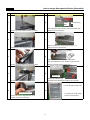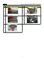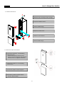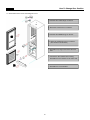
1
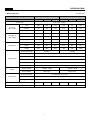
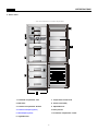
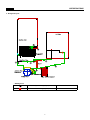
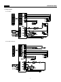
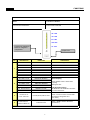
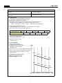
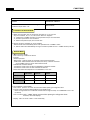
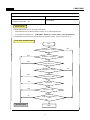
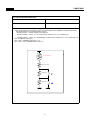
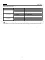
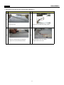
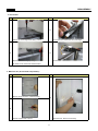
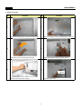
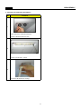
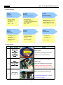
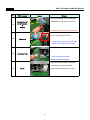
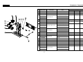
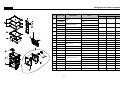
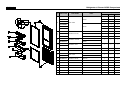
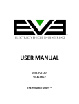
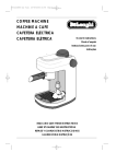
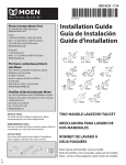
FT32600001
SPECIFICATIONS
* is option code
1. Model Information
Refrigerant Type
R-134a
R-600a
Model No.
RF-T405N** RF-T425N** RF-T455N** RN-T405N** RN-T425N** RN-T455N**
Control Type
FCP Touch control
Total
365
375
404
365
375
404
Freezer
120
120
120
120
120
120
Refrigerator
245
255
284
245
255
284
Total
315
332
358
315
332
358
Freezer
90
90
90
90
90
90
Refrigerator
225
242
268
225
242
268
Width
595
595
595
595
595
595
Depth
651
651
651
651
651
651
Height
1857
1897
2000
1857
1897
2000
Gross Vol.
(ISO 15502)
Storage Vol.
(ISO 15502)
Diemension
Cooling Cycle
Evaporator Type
Fin Type
Condenser Type
Fan Cooling System
Dryer
Molecular Sieve xH-9
Capillary Tube
ID0.7 x T0.55 x L2320
Defrost Type
Automatic Start & Stop
Heater
Electric Part
0.040kg
0.095kg
Refrigerant Charge
Defrost Heater
AC230V, 180W
AC230V, 160W
Defrost Shape
Glass Type
Sheath Type
Freezer Fan Motor
AC 230V/50Hz or DC 12V
Condenser Fan Motor
AC 230V/50Hz or DC 10V
Refrigerator Lamp
LED
Weight
67
69
Blowing Agent
73
70
C-Pentane
1
72
76
SPECIFICATIONS
2. Interior Parts
※ The real features are model dependent
1
10
2
3
4
5
11
6
7
8
9
1. Freshfood compartment LED
7. Temperautre control Knob
2. Multi-Duct
8. Freezer Case (3EA)
3. Freshfood compartment Shelves
9. Adjustable Foot
4. Fresh Care Crisper (option )
10. Dairy Pocket
5. Wine Keeper (option)
11. Freshfood compartment Pocket
6. Vegetable Case
2
SPECIFICATIONS
3. Refrigerant Cycle
- Welding Point
Copper Welding ( Ag 5%)
6 Point
Silver Welding ( Ag 30%)
3 Point
3
SPECIFICATIONS
4. Wiring Diagram
- For AC Motor
- For DC Motor (Europe)
4
FUNCTIONS
1. DISPLAY
INPUT
CONTROL OBJECT
PCB Control Panel Buttons
PCB Control Panel LED
5th LED
4th LED
3rd LED
2nd LED
1st LED
Temperature adjustment
button for refrigerator
compartment.
“Super Cool”
No
1
2
3
4
LED DISPLAY
FUNCTION
OPERATION
3rd LED
TEMP STEP “NOR”
Initially position
4th LED
TEMP STEP “MAX-NOR”
Push “TEMP” button 1 times.
5th LED
TEMP STEP “MAX”
Push “TEMP” button 2 times.
1st LED
TEMP STEP “MIN”
Push “TEMP” button 3 times.
2nd LED
TEMP STEP “MIN-NOR”
Push “TEMP” button 4 times.
LED “S-COOL” on
TEMP S-COOL
Push “S-COOL” button 1 time.
3rd LED is on/off
ERROR R SENSOR.
[Error display]
2nd LED is on/off
ERROR RT SENSOR
1st LED is on/off
ERROR D SENSOR
Push “TEMP” button 5 times while
opening
Refrigator door .
2nd & 3rd is on/off
ERROR DOOR S/W
1st & 3rd is on/off
ERROR “CYCLE"
1st & 2nd is on/off
ERROR “DEFROST"
3rd LED and "SCOOL" LED is on.
Forced (Quick) Defrost Test
1st LED and "SCOOL" LED is on
Pull Down Test
5
The Priorities of Error :
R SENSOR> RT SENSOR> DR S/W>
CYCLE> DEFROST
Push "S-COOL" button 5 times while
opening the refrigerator door.
(not Error )
Push "TEMP" button 30 times.
(not Error )
FUNCTIONS
2. Temperature Control of Refrigerator Compartment
INPUT
CONTROL OBJECT
PCB Control Panel “TEMP” Buttons
PCB Control Panel LED
COMPRESSOR, FAN
R-sensor
A. “TEMP” Button
1. Temperature control of Refrigerator compartment
2. 5 step mode of successive temperature mode
3. Initial mode by power input: step “NOR”
4. Temperature will be set if the button doesn’t get pressed again within 5 sec.
- Whenever pressing “TEMP” button, setting is repeated in the order of
“NOR” → “MAX-NOR” → “MAX” → “MIN” → “MIN-NOR” (LED LAMP ON)
B. Temperature of Refrigerator Control
1. COMP and FAN will be controlled by the on/off condition of each mode.1
2. Temperature Difference of Refrigerator each step :
Temperature Step
“MIN”
Temp. Diff. of Each Step
“MIN-NOR”
1.3C
“NOR”
1.5C
“MAX-NOR”
2.3C
“MAX”
2.2C
3. Temperature of Refrigerator
-1 2C
at step “NOR”
NOR OFF point: is -1.2C
4. Refrigerator ON/OFF Temp.
Difference: 3.4C
C. “S-COOL” MODE
1. Press S-COOL SWITCH
and make S-COOL led lamp on.
2. COMP & FAN are on until R-sensor
reaches to “Over Refrigeration
OFF Point”, -7C
Temp
3. After the reach of -7°C , STEP “MAX” mode continues.
4. When “S-COOL” MODE (Quick Refrigeration Mode)
lasts for about 40 minutes, it returns to general
operation mode.
6.0 C
4.5 C
D. Temperature of Freezer Control
-It will be only controlled by using
“KNOB F LOUVER” in Freezer.
3.0 C
0.8 C
-1.3C
ON
0.8 C
-0.5 C
-2.0C
-4.3 C
-6.5 C
OFF
Step 'MIN'
6
'MIN-NOR'
'NOR'
'MAX-NOR'
Dial
FUNCTIONS
3. Defrost Mode
INPUT
CONTROL OBJECT
Total COMP Work Time / COMP Working Rate
Total Door Open Time / RT
Defrost Mode
Conditions of Defrost Mode
A. When total operation time of compressor becomes: 6, 8, 10, 12 hours.
- any error mode-R1, D1, F3, C1, RT/S, Door SW error- happens.
- or, running rate of COMP (per 2hrs of total operation time) is more than 80%.
- or, total door open time is over 3 minutes.
- or, ambient temperature (RT) is more than 40C.
B. Even if the above condition “A” is not satisfied,
- Defrost mode starts immediately when total operation time of COMP is 14hrs.
- or, defrost mode starts immediately as long as total time (COMP on time + COMP off time) is 60 hrs.
Defrost Mode
A. G
General Defrost Mode
- How to start: By conditions of defrost
- Process :
General operation“PRE-COOL” - Defrost Heater on- Pause(10 min)-General operation
; PRE-COOL: When the defrost heater works, the temp. of freezer increases.
So the COMP works for 25 min before defrost mode.
- Limited Time of Defrost Heater
; 40 minutes: Heater turns off when “D SENSOR” is OPEN or SHORT.
; 60 minutes: Heater turns off after maximum 60 minutes.
- Heater Off: When the temperature at “D SENSOR” is over 10C
PRE-COOL
Defrost
Pause
Compressor
ON
OFF
OFF
Fan
ON
OFF
OFF
Defrost
OFF
ON
OFF
B. Forced(Quick) Defrost Mode
- How to start: push the "S-COOL" button 5 times while opening the refrigerator door.
- Process: same as General Defrost Mode except “PRE-COOL”
; Heater is supposed to be on Initial 30 seconds even though the temp. at “D SENSOR” is over 10C.
(for TEST)
- How to confirm: Push "TEMP" button 5 times while opening the refrigerator door..
And then, the mode displays.
- Display : 3rd & "S-COOL" LED is on/off continually
7
FUNCTIONS
3. Defrost Mode
INPUT
CONTROL OBJECT
Total COMP Work Time / COMP Working Rate
Total Door Open Time / RT
Defrost Mode
Initial Defrost
A. When initial power input or returning power failure.
if the temperature at the Defrost Sensor is below 3.5 C, Defrost Mode starts.
( It prceeds from 'PRE-COOL' ), [ PRE-COOL - Heater On - Pause (10min) - Normal Operation ]
B. Initial defrost mode starts after 'Prevention of Compressor Restart'. ( Refer to function No. 5 )
Flow Chart of Defrost Start
Start
Comp time >= 2 hours
No
Yes
Yes
Total time >= 60 hours
No
Yes
Comp time >= 14
No
Comp time >= 6 hours
Yes
Yes
Comp Rate >= 90%
No
Yes
Any Error?
No
Yes
RT Temp >= 38C
No
Ye
Total door open time >=
2min?
No
Defrosting Start
END
8
No
FUNCTIONS
4. Prevention of Compressor Restart
INPUT
CONTROL OBJECT
COMP
COMP. doesn’t work after COMP turns off even though R-sensor is on condition. (This is to protect comp.)
A. General operation (Temp. at the RT sensor is over 20C): The COMP can’t be on within 6 min.
B. Operation of LOW RT (Temp. at the RT sensor is below 19C):
The COMP can’t be on within 30 min.
(But the COMP can be on after 6min when the doors open more than 20 seconds.)
5. Buzzer Sound
INPUT
CONTROL OBJECT
Control Buttons / Door Switch
Initial Power Input
Buzzer
A. Whenever “PCB Control Panel” button’s pushed, the buzzer rings.
B. After 2 minutes power’s on, the buzzer rings 3 times.
C. Time of Buzzer: Forced Defrost Mode (3 times), Short Circuit Test (1 time)
D. When door opens, the buzzer rings every 1 minute for 5 minutes.
9
FUNCTIONS
6. Control of R-sensor OFF Point
INPUT
CONTROL OBJECT
”J1” , “J2” On Main PCB
Control Resistance of R sensor OFF Point
A. LOW COOLING OPTION ( Weak Cooling )
- When the refrigeration of refrigerator is poor or weak though Fan and COMP are working continuously,
the following actions are recommended for service.
- Resistance (R47) : Default resistance (31.4Kohms)
-
Resistance (R45) : Cut the “J1” off to reduce basic resistance by 1.5°C. (2Kohms up)
- Resistance (R42) : Cut the “J2” off additionally to reduce basic resistance by 1.5°C. (total 4Kohms up)
R47 = R-SENSOR OFF point
R47 + R45 = R-SENSOR OFF point - 1.5C
R47 + R45 + R42 = R-SENSOR OFF point - 3C
R-SENSOR
R47(31.4K)
R45(2K)
J1
R42(2K)
J2
10
FUNCTIONS
7. Error Display
INPUT
CONTROL OBJECT
PCB Control Panel Buttons / Door
LED Lamp
- ERROR DISPLAY
- To check the appliance has error or not, push TEMP button 5 times while opening the refrigerator. door.
- To stop the Error Display Set, push “TEMP” button 1 times, or wait 4 minutes.
A. R1 ERROR (It happens when R-Sensor is OPEN or SHORT)
- DISPLAY : 3rd LED is on & off continually.
- CONTROL :
; Controlled by the following condition of RT
; When “RT ERROR” happens at the same time, “COMP. ON/OFF Operating Time” is 16min/24min.
(Unit : min)
RT sensor TEMP
~13C
~19C
~29C
29C ~
COMP. Operating TIME
(ON/OFF)
6/34
10/30
16/24
20/20
- Termination : when R-Sensor is normal.
B. RT ERROR (It happens when RT-Sensor is OPEN or SHORT)
- DISPLAY : 2nd LED is on & off continually.
- CONTROL : Delete the conditions of “RT-sensor Control” and operate normally.
hen R
Sensor is normal.
normal
- Termination : when
R-Sensor
C. D1 ERROR (It happens when D-Sensor is OPEN or SHORT)
- DISPLAY : 1st LED is on & off continually.
- CONTROL : Defrosting is active maximum time (40 min)
- Termination: when D-Sensor is normal.
D. DR ERROR (It happens when the system senses door opens more than 1 hour.)
- DISPLAY : 2nd & 3rd LED are on & off continually.
- CONTROL : Deletion of function related door switch sensing
- If door switch (open & close) is sensed, the error is terminated automatically.
E. C1 ERROR (When D-Sensor is more than -5C, Comp operates continuosely over 3 hrs)
- DISPLAY : 1st & 3rd LED are on & off continually.
- CONTROL : Normal operation.
- Termination : When Comp is off, D-Sensor is less than -5C.
F. F3 ERROR (When defrosting is active for 60 minutes. )
6.1- DISPLAY : 1st & 2nd LED are on/off continually.
6.2- CONTROL : Skip the Pre-cool process.
6.3- Termination: When defrosing ends by the defrost sensor.
- If the appliance is normal (no error), just 4th and 5th LED is on/off in Error Mode.
11
FUNCTIONS
8. Function Key Summary Table
MODE
Forced(Quick) Defrost Mode
Pull Down Mode
Error Display
Action
Button / Remark
How to enter the Mode
S-COOL 5 times + Refrigerator door open
How to terminate
After mode end or unplug.
Display
3rd and S-COOL LED is on.
How to enter the Mode
TEMP button 30 times
How to terminate
After mode end or unplug.
Display
1st and S-COOL LED is on.
How to enter the Mode
TEMP 5 times + Refrigerator door open
How to terminate
After 4 minutes or unplug.
Display
4th and 5th LED is ON/Off (When no error )
In Error Mode, you can find the current mode ( What mode is operationg ) and what kinds of Error happen.
12
DISASSEMBLY
1. Front PCB ( some parts can vary from the actual appearance. )
Procedure
No
1
Procedure
No
3
Remove cap cover.
2
Pull the FCP FIXTURE UP by using (-)driver.
4
Separate the F-PCB housing from refrigerator.
After separating F-PCB from fixture ,
Be careful not to scratch the cabniet surface.
change the FCP to new ones
13
DISASSEMBLY
2. Door Switch
No
Procedure
No
1
Procedure
3
Remove top cover hinge screw with (+) driver.
Remove the Door Switch from the cover hinge.
2
4
Separate the Cover hinge by using driver.
Disconnect door switch connector.
Be careful not to scratch the cabniet surface.
3. Multi-Duct As ( In Freshfood Compartment )
No
Procedure
No
Procedure
1
Remove screw cap with (-) driver(2 points)
3
2
Unscre 2 points with
Unscrew
ith ((+)driver
)dri er
Disconnect the Sensor wire
ire housing.
ho sing
14
DISASSEMBLY
4. Freezer Louver As
No
Procedure
Procedure
No
1
4
Unscrew the fixing screw to remove the Louver F As
Remove 3 screws in order to disassemble Louver F As.
2
5
Remove the Louver F As pulling the top side.
When disassembling check the Knob position.
3
6
L M H
Disconnect Fan motor wire housing.
Default position is 'M'
15
DISASSEMBLY
5. LED Lamp ( In Freshfood Compartment )
No
Procedure
1
Using a thin driver, Pull both locker and
Separate a Window LED from Liner.
2
Unscrew 2 points with (+) driver
3
Disconnect LED PCB form housing.
16
How to change Door opening Dirction (Reversible)
No
Procedure
Procedure
No
Button
1
Hidden
Wire
6
Cover Bushing
After hiding door wire harness, remove the button Door
Remove top cover hinge screw with (+) driver.
2
Switch and Cover Bushing.
7
After unscrewing the Cover Hinge Harness *T *L,
Separate the Cover hinge by using driver.
disclose the door wire harness.
Stopper
3
8
Reassemble the cover and button door switch.
And also assemble the door stopper to opposite side.
Remove the Door Switch from the cover hinge.
4
(Which is located the Door under Cap. )
9
Freezer Door
Remove the Middle Hinge.
Disconnect all wire connector and hinge.
Assemble Cover Bushing & Stopper to the opposite.
a. Change the location
(screw & division hinge cap)
5
10
Refrigerator Door Cap
b. Change the unnder hinge
Unscrew the Cover Hinge Harness *T *R
location to the opposite.
and hide the door wire harness.
17
How to change Door opening Direction (Reversible)
No
Procedure
No
11
Procedure
14
Screw the middle hinge to fix the Freezer Door.
Connect the wire harness to door swtich.
( Washer should be up. )
( Be careful the dircetion. )
12
15
Also assemble wire cover on the top plate. ( On the right
13
Change the plate position and separate door switch.
18
Assemble Door and hing cover.
How To Change Door Position
1-1. Remove the Door As
a. Remove 'Top Cover Hinge' and 'Top Hinge'
b. Separate 'Refrierator Door'.
c. Remove 'Middle Hinge'
d. Separate 'Freezer Door'.
ⓑ
e. Remove 'Cover Bracket'.
ⓓ
f. Remove 'Under Hinge'.
1-2. Reverse the Door Accessories
ⓙ
ⓖ
g. Reverse the position of 'Cover Bushing
Refrigeraor Door'
- Unscrew and remove 'Harness Cover'.
- Take out 'Left Door Harness' and assemble
'Harness Cover' on 'Right Door Harness'.
h. Reverse the position of 'Cover Bushing
Freezer Door'.
ⓗ
i. Reverse the position of 'Door Stoppers'.
J. Reverse the position of 'Button Switch'.
- Unscrew 'Button Switch'
19
How To Change Door Position
1-3. Reassemble the Freezer and Refrigerator Door
j. Assemble the 'Under Hinge' on the left.
k. Attach the 'Freezer Door' to Cabniet.
l. Assemble the 'Middle Hinge' on the left.
ⓜ
m. Attach the 'Refrigerator Door' to Cabinet.
( Be careful not to fall down )
n. Assemble 'Top' hinge and connect the FCP
wire.
o. Connect the 'Door Switch' wire housing.
Assemble the 'Door Switch' on the other side.
ⓟ
p. Assemble the 'Cover Bracket'.
20
How To Charge R-600a Refrigerant
1. Safety Warning ( R-600a Refrigerant Models)
This appliance contains a certain amount of isobutane refrigerant (R600a) a natural gas with high
environmental compatibility that is, however, also combustible.
When transporting and installing the appliance, care should be taken to ensure that no parts of the
refrigerating circuit are damaged.
Refrigerant squirting out of the pipes could ignite or cause an eye injury. If a leak is detected, avoid
any naked flames or potential sources of ignition and air the room in which appliance is standing for
several minutes.
- In order to avoid the creation of a flammable gas-air mixture if a leak in the refrigerating circuit occurs, the size of the room
in which the appiance may be sited depends on the amount of refrigerant used. The room must be 1m3 in size for every 8g
of R600a refrigerant inside the appliance. The amount of refrigerant is shown on the identification plate inside the appliance.
- Never start up an appliance showing any sings of damage. If in doubt, consult your dealer.
2. Tools
21
How To Charge R-600a Refrigerant
3. Process Summary
1st Step.
R-600a ref.
discharging
2nd Step.
Removing
the remaning refrigerant
- Connect the discharging hose to
the outdoors.
- Time : 7 min.
4th Step.
Welding
coupling pipe
Coupling cap and
gas charging cap
should be
seperated before
welding.
3th Step.
Exchanging comp.
& dryer / pipe welding
- For removing of
remaning refrigerant.,
connect the discharging hose to
the vacuum pump
-Time : 10min
- Exchange Comp. and Dryer
- Welding the Pipe
- Copper-Copper : 5% rod
- Copper-Steel : 30% rod
6th Step.
Charge R-600a
5th Step.
Vacuum
- Check the vacuum
with (mani-polder)
gauge
- Charging the ref.
on POWER ON
- Time : 60~80min
- Time : 10min
4. In Detail Precess
NO.
SVC process
1
Connecting
the
pinch-plier
&
discharging
hose
Image
Details
1. Connect the discharging hose to
the pinch-plier
OUT DOOR
2. The outlet of discharging hose should
be placed to the outdoor(window)
1. Fix the pinch-plier to the compressor
2
charging pipe.
Fix ing
the pinch-plier
&
charging pipe
2. Pinch-plier should not be moving freely.
※ If that is moving freely, it would cause
fire/explosion as leakage gas in the room.
1. Discharge the R-600a ref. to outdoor.
[Befor connecting the vacuum pump]
3
Discharging
the R-600a ref.
※ It should have enough time more than
7 minutes to discharge.
22
How To Charge R-600a Refrigerant
NO.
SVC process
Image
Details
1. And then, connect the vacuum pump
to the outlet of discharging hose
4
Remov ing the
remaining ref.
※Vacum pump should be placed at
the outdoor where is able to clear air easily.
※ It should have enough time
more than 10 minutes to discharge.
1. Disassembe the each pipe (Del-pipe,
Suc-pipe, Capi-pipe, Dryer & Hot-pipe)
5
Remov ing the
pinch-plier & pipe
※ Caution ; A part is easily damaged
by flame so that disassemly should
be done carefully.
1. Change the comp. & dryer.
6
Ex changing comp
& dry er
p spec.
p
※ You should check the comp.
and assemble correctly.
1. Weld the each pipe.
7
8
※ O Copper-Copper welding - 5% rod
W elding
△ Copper-Steel welding - 35%
30%rod
rod
Disassembly
of charging v alv e
(Coupling pipe)
Valve Ass'y
1. Decap the couplig pipe cap and
Valve Ass'y
disassemble the vlave ass'y.
※ If you don't disassemble, the coupling
rubber would be melted.
23
How To Charge R-600a Refrigerant
NO.
SVC process
Image
Details
1. Weld after inserting the coupling pipe
to the compressor.
9
Coupling pipe
welding
※ Use the wet cloth for preventing the
other part of machinery-room from damage.
1. Reassemble the valve ass'y with
coupling pipe to clockwise.
2. Connect the blue hose of the guage
to the coupling pipe and the yellow hose
10
Valv e reass' y
&
guage connecting
to the vacuum pump.
3. Open the blue guage lever
and start the vacuum pump
1. Be vacuumed the cycle with pump.
11
※ Time : 60~80min
Vacuum
=> If the vacuum time is less than 60min,
ref. COP & air coolong would be weak.
1. Check the guage : -76㎝Hg
12
Check
※ If the cycle is not vacuumed,
it would be leak.
1. Check the amounts of R-600a can
with scale and discharge the surplus ref.
13
※ Discharging is surely done at the outdoor
where is able to clear air.
Adjusting
the amounts of
refrigerants
(R-600a can)
※ Tip of adjusting.
- Can total weight :160g(Can 75g+Ref. 85g)
- Adapter : 145g
=> Total : 305g
- The amounts of charging : 79g
=> Discharging : 6g => Total : 299g
24
How To Charge R-600a Refrigerant
NO.
SVC process
Image
Details
1. Conect can adapter to the coupling pipe.
14
2. Charge the ref. with open lever slowly.
Connecting of
coupling pipe
&
adapta
※ Refrigerant should never leak in the room.
1. On the power of refrigerator and then
start to charge the ref. (10min)
15
Charging
※ Charge the ref. until going out the water
vapour condensing on the can outlet.
1. Check the leakage.
16
Leakage Test
※ You must rework from Step.1
when the leakage is detected.
1. Clean and clear around the machinery
room when the service is finished.
17
Finish
2. Assemble the machinery room cover.
25
Cabinet
Cabinet Compartment
Q'ty
NO
PART-CODE
1
-
2
PART NAME
SPEC.
T405..
T425..
T455..
ASSY CAB URT
BLACK / WHITE
1
1
1
3012929000
HINGE *T AS
RFP-340
1
1
1
3
3001427700
COVER *T AS
PP (WHITE)
1
1
1
4
3018125601
SWITCH H/BAR DR AS
SP101B-2D1
1
1
1
1
1
1
V3 COMBI(AC FAN)
1
1
1
V3 COMBI(DC FAN)
1
1
1
1
1
1
PP(WHITE)
3001412200
5
COVER CAB HRNS
PP(T/SILVER)
3001412220
30143HN060
6
PCB MAIN AS
30143HN090
SPCC(WHITE)
3001416600
7
COVER M/PCB BOX AS
SPCC(BLACK)
3001416630
8
3012928600
HINGE *M
PO, T3.2
1
1
1
9
3012928800
HINGE *U
PO, T3.2
1
1
1
10
3012104600
FOOT ADJ AS
PP+INSERT
2
2
2
11
3001442200
COVER CAB BRKT AS
PP (WHITE)
1
1
1
48
30143HJ210
PCB FRE LED AS
6-LED FR-4 120X20-1.6T
1
1
1
49
3015517200
WINDOW F LED *T
ABS
1
1
1
Cabinet
Compressor Compartment
Q'ty
NO
PART-CODE
12
3010349300
13
OPTION
PART NAME
T405..
T425..
T455..
BASE COMP AS
RFP-340
1
1
1
CORD POWER AS
RFP-340
1
1
1
1
1
1
4
4
4
4
4
4
1
1
1
1
1
1
LZ88CY (A+,EUROPE)
3956188C50
14
3956158K50
COMPRESSOR
16
3016002500
SPECIAL WASHER
SK-5 T0.8
3010101480
ABSORBER COMP AS
SPRING (R-600a)
3010101600
ABSORBER COMP
NBR (R-134a)
B60-120(LZ88CY)
3018133020
17
3018131810
SWITCH P RELAY AS
LZ88CY (A+,EUROPE)
3811402600
381140050
COVER RELAY
20
21
3011122800
CASE VAPORI AS
PP + TAPE ALUMINUM
1
1
1
3013202700
HOSE DRN B
PE
1
1
1
1
1
1
3015918110
MOTOR C AS
3015906850
22
YX58LHP5
MD4A1Q-L1U
3811400503
19
YX58LHP5
MD4A1Q-L1U
3018132900
18
YX58LHP5 2
MD4A1Q-L1U
3956141250
15
SPEC.
AC 230V/50HZ
DC 10V
3010102100
ABSORBER C MOTOR
NR FRB -5350NT
1
1
1
23
3011802200
FAN
ABS OD3.17XD110
1
1
1
24
3014469600
PIPE WICON AS
1
1
1
25
3016808100
DRYER AS
SBS 12G
1
1
1
26
3001414000
COVER MACH RM AS
RFP-340
1
1
1
28
3016405800
1
1
1
400VAC /4uF(LZ88CY)
301640600
3016406100
27
CAPACITOR RUN
350VAC/4uF(YX58LHP5)
400VAC /5uF(MD4A1Q-L1U)
Cabinet
Refrigerator & Freezer Compartment
Q'ty
NO
27
PART-CODE
3017065200
PART NAME
EVA AS
3017068200
27-1
30127694100
HARNESS D SENS
3012769400
27-2
29
SPEC.
R-134a
R-600a
R-134a
R-600a
3012822000
HEATER D AS
R-134a (GLASS)
3012823000
HEATER SHEATH AS
R-600a
3018927900
LOUVER F AS
RFP-341, AC FAN
T405..
T425..
T455..
1
1
1
1
1
1
1
1
1
1
1
1
3018927950
LOUVER F AS
RFP-341, DC FAN
1
1
1
29-1
3018923700
LOUVER F A AS
LOUVER F A+SEAL
1
1
1
29 2
29-2
3018923800
LOUVER F B AS
1
1
1
29-2-1
3011836000
FAN AS
1
1
1
29-2-2
3015918210
MOTOR F AS
3015905350
FAN+CLAMP
AC 230V/50HZ
1
1
1
DC 12V
1
1
1
29-2-3
3010664700
BRACKET FAN MOTOR
PP, T2.0
1
1
1
30
3011198000
CASE F C AS
CASE+WINDOW
1
1
1
31
3011197900
CASE F B AS
CASE+WINDOW
2
2
2
34
3010564910
CASE ICING AS
CRYSTAL
1
1
1
ABS, RFP-326
1
X
X
COVER MULTI DUCT
ABS, RFP-346
X
1
X
3001439500
35
3001439600
ABS, RFP-356
X
X
1
35-1
3012764600
HARNESS R SENS
NBC-K43-D21
1
1
1
36
3011197500
CASE VEGETB
GPPS
1
1
1
37
3001438700
COVER V/CASE AS
COVER+KNOB
1
1
1
38
3017851900
SHELF R INSERT AS
PP
3
3
3
3001439700
28
Cabinet
Refrigerator & Freezer DOOR Compartment
NO
PART-CODE
PART NAME
T405..
T425..
T455..
1
x
x
x
1
x
x
x
1
1
x
x
x
1
x
x
x
1
RFP-326
1
x
x
RFP-346
x
1
x
RFP-356
x
x
1
1
1
1
1
1
1
30100A6210
BLACK
30100A6310
39
30100A6410
ASSY R DR
30100A6200
WHITE
30100A6300
30100A6400
3012327700
391
3012321200
GASKET R DR AS
3012327800
40
3012037300
FIXTURE F PCB AS
3012037310
40-1
3012035800
FIXTURE F PCB
3012035810
Q'ty
SPEC.
WHITE
BLACK
WHITE
BLACK
40-2
30143HN170
PCB INTR FRONT AS
RFT-346
1
1
1
40-3
3012779300
HAARNESS INTR FCP AS
RFT-326,346,356
1
1
1
1
1
1
41
30100A6300
ASSY F DR
30100A6310
WHITE
BLACK
41-1
3012321100
GASKET F DR AS
RFP-340
1
1
1
42
3019056100
POCKET DAIRY AS
RFP-341
1
1
1
43
3011190800
CASE EGG TRAY
GPPS
1
1
1
44
3019055900
POCKET BOTL
GPPS
1
1
1
45
3019059700
POCKET R *M
GPPS
1
1
1
46
3019055800
POCKET JUMBO
GPPS
1
1
1
47
3012532100
GUIDE BOTL POKT
HIPS
1
1
1