1
YORK.
SINGLE
INSTALLATION INSTRUCTION
Supersedes
SUNLINE SERIES
PACKAGE AIR CONDITIONERS
Tab DSV
530 25-N2Y (488)
530 25-N2Y (1 189)
035-08597
MODELS DISV/D2SV300,
360 & 480
.. .-
‘1 “
1
I
GENERAL
1.
-
J-
r
--7----
1,
]
-1 i~
---
1
~
530
25-N2
TABLE OF CONTENTS
MAINTENANCE
GI:NERAL
INSPECTION
REF1 REN(’I
FILTERS ., . . .
... , . . . .
. . . . ...
. 24
COILS . . . . . . . . . . . . . . . . . . . . .
.,
24
DRAIN PAN
.
24
LUBRICATION . . . . . . . . . . . . . . . . . . . . . . . . 24
BELTS
.
....
.
24
REFRIGERANT CtlARGE R-22
24
1
I
1
NOMIN(’LAT(IRL
INSTALLATION
2
ATIOXS
RI(;GINC;
kloliNTING
(’L1;ARAN(’t S
3
3
.3
.3
coNDLNsATI.DRAlk”
CONN1(TION
POWLR AND (’ONTKOLW[RING
4
L[ M IT
Powc[ Wll
(’ontfol
r)~l(”_f
Ing
I
>
<
4
.,,
Wiring
COP4SL(’
FIGURE
.,,
6
rloNS
11
11
f-lLT1 KS
::
:::
1(’ONO\llZf R RAIN’H6fi)~’bPTiOiV’
FIXEDOUTDOOR AIRRAINHOOD
12
12
:
]~
IXliAUST AIR RAIN HOODOPTION .,
STATIC PRESSUREREGULATOR AND CONT”ROL: 12
10
11
12
13
14
15
16
17
18
][]
OPERATION
DISV VARIABLE AIR VOLUME .,
GENERAL . . . .
COOLING
.,
.’:
Economizer System,
.,
.
Damper Linkage Adjustment,
., .,
:::
.
Hwrtmg Systcm
Au Volume Control System
Check]ng Llnk~geon Alr Volume D~m”pers
Checkout Procedure
Exhaust Alr System
SUPPLYAlR BLOWERADJUSTM1+T
:
MASTLRPRINTLD CIRCLIITBOARD AND
PLUC;-IN RELAY ASSEMBLY
SE.f<VICE.ANALYZt R
FIXED OUTDOOR AIR ADJUSTMENT :
t:XllAUST AIR PI RFORMAN(’L
12
12
: 13
14
14
14
14
15
15
15
: 16
LIST OF ILLUSTRATIONS
Un It Le;$ P;incls
r~ pIcdl Un] t Rlgg(ng
(’enter (JI Gr~v]ly
lk~omn]cndcd
Drain P]prrrg
Bottom Power Wrrlngl.ntran~e
START-UP
.-)’-!
.
7-J
-23
.23
1
7
3
4
5
6
7
8
9
10
11
~
3
3
4
5
5
6
6
Side Puwer Wlrlnglmtrancc
Control Wumg Entrance (DSV300,”360) ~:
Control Wlrmg Entrance (DSV480)
Control Wrrmgand Static Pressure Connect inns, D 1SV Un]t With A]r Volume
Dampers
Un]t l)lnlcrr~lons
.. ..
Duct Conncctlons
... .
Sound Ahsorptlon Chamber
.
7
10
11
Internsl V[ewof Damper Motor End Swltcb
Adjusting Damper Motor End Switch
Typical Motor Mountlrrg Assembly
IIole Locations For Supply Alr (’FM (’beck
Pressure Drop Acruss IIvapordtor (’oil
I;rxcd Outdoor Alr AdJir\tnlcnt
l;xhaus[ Arr Pert orlmince
11
: 1s
15
16
17
17
19
19
LIST OF TABLES
TABLE
18
18
19
19
PRE START-UPCHECKS
pre-stsrt Steps and procedures
INITIAL START-UPCHECKS
SAFETY AND SERVICE FEATUkES
4
5
6
7
8
9
-
Appllcti[lon lli[a
Cunlponcnl Wcight~
Llcctrlcdl Dtita
I-rltcr Kcqulrcrnentj
Ambient Thernmstat %ttlng
En[halpy (’ontroi ( %[ Ilrlnt
4
4
. 8
11
14
“B’
. .
Supply Arr System Adjustment
ScrvrceAnaly/cr Function Chart
Blower Motor And Drlvc Da[ir
Rc\rsttsr]cc\- Untt Options ~nd Atxc\sorm~
Supply Alr Blower Pcrlormancc
-
14
16
18
20
20
21
I
I
,=
ink-l
I
J
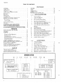
COOLING
CAPACITY
PRODUCT
IDENTIFIER
300 = 25 Tori
360 = 30 Ton
480 = 40 Ton
-
SV = VAV Sunllne
FACTORY
INSTALLED
E = Electric
G = Gas (Multl-Fuel)
A = Not Applicable
H EAT
‘aEa
NOMINAL
HEATING
Gas
400 = 400 Mbh
560 = 560 Mbh
800 = 800 Mbh
CAPACITY
Electric
040
060
080
100
120
= 40 KW
= 60 KW
= 80 KW
= 100 KW
= 120 KW
con troll E IIVIronmf,llt,i
2
-
I
Syslf,ms
SUPPLY AIR
B LOWER
EVAPORATOR
530
COIL
25-N2
\
-F
I LTERS
\
RETURN AIR
COMPARTMENT
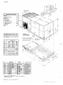
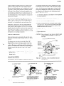
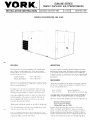
FIG. 1 – UNIT LESS PANELS (DSV 480 SHOWN)
INSTALLATION
LIMITATIONS
These units must be installed in accordance with all natiunll
and local safety codes. If no local codes apply, installatlon
must conform with the appropriate nationa] codes, See Table
I for application data. Units are designed to meet National
Safety Code Standards. If’components must be added to a
unit to meet local codes, they are to be installed at the dealer’s and/or the customer’s expense.
u
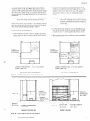
RIGGING
w]th lifting lugs on the unit base.
Units should be lifted by placing rigg]nghooks thru the ILIgs
provided. Spreader bars should be used, See Fig. 2.
Sunllne units are equipped
CLEARANCES
These units must be ins(alled with the mmimum clearances
hsted below,
36” for Service Access
to Controls
Front
(Control Box Side)
Left side
(Condenser coIl)
Rear
36” for Proper Condenser Air Flow
36” From Rain Hoods
36” Units w!th Electrlc Heat Opt Ion
36” CoollngOnly Units
Right side
o“
Below unit’
Above unit
‘Units wnh
tible floor.
an
120” for Condenser Air Discharge
electrlc heating option can be Installed on
a combus-
A 2“ clearance within 3 feet of the unit must be nlalntiuned
between any combustible mater]al and the supply air duct
work.
No objects should be left near the combustion air inlet to
obstruct the openings. If the unit ISslab mounted, shrubs
and other growth should be eliminated.
FIG. 2 – TYPICAL
UNIT RIGGING
CONDENSER
COIL
END
MOUNTING
The structure on which the unit or roof curb ISmounted
must be capable of supporting the total weight of the unit.
Refer to Table 2 for individual component weights. Refer
to Figure 3 for approximate centers of gravity.
L
A roof mounting curb accessory 1savailable to simplify the
installation of a Sunline unit. Refer to Form 530.25-N1.6
for installation instructions for assemblingand mounting
the curb and for installing the unit on the curb. Roof mounting curbs capable of supporting the unit’s weight may also be
field fabricated.
Central
Enwronmental
Systems
DSV300
141
47
DSV360
164
48
77
.-——
84
DSV480
184--
45
104
FIG. 3 – CENTER OF GRAVITY
3
53025
N2
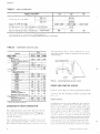
TABLE 1 –APPLICATION
DATA
MODEL DISVID2SV
b
Vol taqc Val Iatl on, MIn/Max 1
I
I
L—.
——–.-—-
480
180/220
2i7!253
414/506
——
—
230 Volts
-1
I
360
200volts
~...— 460 Volts
Supply Alr CFM, Mlnz /Max
300
I
.—.
520/635
575 volts
–
‘&600/14,400
.3,000/12000
. ..
Wet BLIIb Temp ( F) of Air on Evapolator CoIl, Mlrr/Max
57/72
‘-‘-- ‘“35~i
--DI v ‘Bulb TemD. ( ‘F; of Alr on Condensel Co,l. Mln/Max ---t .
15
[ 4,800/1 9<200
180
1Ur II /at 1[]11 R,II>[II>“A II ,ICCor d,I IICV LVI f h AR I Standard 110
2 Hot gas bypass
WI I I be req L.Ired If the C FM drops below
the mln Imum
values shown
TABLE 2 – COMPONENT WEIGHTS (L8S. )
MODEL
BASIC UNIT*
Options
Economizer
SUPPIY Air Motor & Drive
7-1/2 HP
10 HP
15 HP
20 HP
Heatincl
Nat;ral Gas Heat
G400
G560
G800
Electric Heat
E040
E060
E080
E1OO
El 20
Exhaust Fan
Discharge Dampers &
Actuator (DSV units only)
1Ilc
DSV
480
300 1 360
3135
3675
4480
220
220
247
130
145
—
—
—
—
.
145
185
—
( I .Ip lllu\l
lln(i~l
lx? J(
It<l.l 2“ (ice}) I!1 111.1111(1 In
J 1! I)1x’ 1J [ 111~L{ llldl [ II) II}
J I c \l .1I t Iny
L’\[K’L la] I\
,! N ,11L’1 W’<iI
\\ t1(>II [ I IC t) II I\\ c>I j
LIp
UNIT
CONDENSATE
DRAIN
CONNECT
~..
ION’\
–.
185
215
2“
—
140
240
—
140
240
—
240
340
50
55
60
65
—
160
50
55
60
65
70
160
50
55
60
65
70
250
125
125
150
*
/
l)RAl N ‘-b
P LLJ[-,
TRAP
FIG. 4 – RECOMMENDED DRAIN PIPING
POWER AND CONTROL WIRING
Accessories
Roof Mounting Curb
300 1 350
End Outlet Kit
105
“WI th fl xed outdoor
105
400
I
130
POWERWIRING
alr opt, on
CONDENSATE DRAIN CONNECTION
I
c’ II It II
1,11 Illfl
c I Ilc \ll )[IL’dJplIll: pill i{ IIILI1AL’(’Ih I Ilc IIIu III III)
r \l I II
{ I IL! p( l\\
11(
1[II I II[i ,1()1IL,(I\))l
A
c I l\l:
Ing
pill
[10
,Ind
(Iq!l
[ IIL’
t’c>
I
L II )L L \i I’1(’ ,111 d
4“
I)( )
II
f (l-
I c pb
L1.’
530.25-N2
b
A non-fused disconnect switch is availableas a factorymounted option on all units. When this option is not included, a field-supplied disconnect switch should be installed in the power supply wiiing at a location that will meet
the requirements of the National Electric Code and/or local
regulations.
~njts that are Illounted
on structural steel above the
finished roof unless the steel is blocking the 4-112inch
diameter sleeve]n t Imbase ot’tile unit. TbIs ~pplies t(]
urrltswitb or WIIh(lut a f~ctolJ’InstaIled disconnect
Swltcb
,}’OTI [-((,wddi~cIJrItIc’(r
sit$it[lw~urc not req((vwf becut(se
tll~ po~tw w’ir[t)gttrust bc jiised at the source.
CAL’TIOIV The 4-1/2 inch slme must be sealed a]ter
(h<’power }~’irmgIrasken rotited to ptwvnt
possible condensation problcrns in the utlit
<ywtr()1box.
Eltber Inverse [[me clrcult breaker or LIWII
element time dekry tuses may be used for overcurrerrt protect l[~non these
units They must be swed according to Table 3.
Sideentry is recommended f(l]:
Bottom entry ISrecommended tor:
1. Curb mounted units without a factory installed disconnect switch because the power wiring must be brought
outside the unit to a field supplied disconnect sw]tch.
1, Curb mounted units with a factory installed disconnect
sw]tcb unless the power wiring is already above the fin]shed root,
CONOU
2. Slab mounted units with or without a factory installed
..
disconnect sw]tch,
CONDUIT
IT
CONNECTOR
CONNECTOR
(3” Threaded)
(3” Threaded)
\
1
CONDUIT
PLATE
w
TERM I NATION
(35/8”
J
\
4.1 /2”
DIA
CONDUIT
SLEEVE
PLATE
K.O )
4.1 /2”
TERMfNATION
(3-5/8”
DIA
SLEEVE
K. O.)
UNITS WITH DISCONNECT
UNITS WITHOUT DISCONNECT
FIG. 5 – BOTTOM POWERWIRING ENTRANCE
,
I
I
CONDUIT
3-5/8”
CONDUIT
CONNECTOR
K O
-
\
- CONNECTOR
(3” Threaded)
(3” Threaded)
(BY YORK)
(BY YORK)
,
CONDUIT
TERMINATION
1
/
/
A. J
,
PLATE
] (3-5/8”
CONDUIT
(BY FIELD)
STRAIGHT
CONNECTOR
(BY F I ELD)
L
MODELS DSV300, 360
K.O )
—.
—4-- —\
\
/
OUTLET
3-518 ’’’O.O
.
BOX
\
- \:
-1
,.
7
<
FLExlBLE
CONDUIT
( Die Cast)
( Liquid Tight)
(BY FIELDI
(BY F I ELD)
MODEL DSV480
FIG. 6 – SIDE POWER WIRING ENTRANCE
Central Environmental
Sys[ems
5
530,25-N2
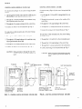
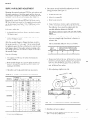
CONTROL WIRING (MODELS DSV300, 360)
CONTROL WI RING (MODEL DSV480)
For bottom entry (Figure 7), the control wlrurgshould be
routed:
For bottom entry (Figure 8), the control wiring should be
routed
1. Up through the flexible conduit and the middle deck to
the proximity of the hole into the control box.
1. Up through the 2-1/4 mch O,D. tubing behind the control box.
2. Through the 1-3/8 snap bushing m the condenser evaporator partition and control box.
2. Through the posltmncd ty-wrap on the outside of the
control box.
3. Through the 2 ty-wraps positioned in the control box.
3. Through the I -3/8 snap bushing in the control box.
4. Connect the wires to the terminal block per Fig. 9.
4. Through the 2 ty-wraps pos]t]oned m the control box
5, Connect the wlrirrgto the terminal block per Fig. 9.
For side entry on slab mounted units, the control wiring
should be routed:
For side entry on slab mounted units, the control wiring
should be routed.
1. Through the 1-1/8 mch K.O. in the corner post.
1. Through the 1-1/8 inch K.O. In the mtermedlate post.
2. Through the 1-3/8 snap bushing in the condenser evaporator partition and control box.
2. Through the 1-3/8 snap bushing in the control box.
3. Through the 2 (y-wraps positioned in the control box.
3. Through the 2 ty-wraps pmtioned in the control box.
4. Connect the wires to the terminal block per Fig. 9.
4. Connect the wiring to the termmal block per Fig. 9.
CAUTION: Wiringpenetration through the side entr.v)
must be sealed to prevent the entrance of
water,
CAUTION. Wiringpenetration through the side entry
must be sealed to prevent the entrance of
water.
1-1 /8” K O
R SIDE ENTRANCE
EXISTING
TY-WRAPS
1-3/8”
SNAP
EXISTING
BUSHING
TY-WRAPS
1-3/8”
SNAP
BUSHING
(BY YORK)
II!/
2-1 /4” O D
TUBING
‘TRY
I BY YORK)
\
t ‘BOTTOM
t
t
/
TERMINAL
B LOCK
FOR STATIC PR ESSURE CONTROL
CONNECTIONS
b-’
FLEXIBLE
CONDUCT
(BY YORK)
FIG. 7 – CONTROL WIRING ENTRANCE (DSV300, 360)
6
I
TERMINAL
BLOCK FOR
STATIC PRESSURE
CONTROL
CONNECTIONS
\
1.1 /8”
FOR
K O
SIDE
ENTRANCE
FIG. 8 – CONTROL WIRING ENTRANCE (DSV480)
Central Environmental
Systems
ENTRY
530 25-N2
a
<
3
@
a
o
0
a
in
m.
m
I
133A*
-t
FIG. 9 – cONTROL WI RING AND sTATlc pREssu RE connections
Central Envltonmental
Systems
(UNIT WITH AIR VOLUME DAMPERS)
7
530.25-N2
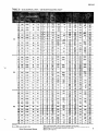
TABLE
3 – (A) ELECTRICAL DATA – UNITS WITHOUT EXHAUST AIR FANS’
~
)&w
—
w
..
—
17
208
25 (1) 101
470
0.84
28
230
25 (1)
470
0.76
92
300
/. 1/.?
200 10
71/2
230 10
460 7.1/2 11
10
14
46
460
25 (1)
46
235
0.76
58
575
25 (1)
37
200
0.76
17
208
30 (1)
126
565
0.90
28
230
30 (1)
122
565
0.81
46
460
30 (1)
61
283
58
575
30 (1)
49
230
17
208
20 (2)
83 ea. 428ea. 0.90ea.
208 F.
28
230
20 (2)
80 ea. 428ea. 0.81ea.
46
460
20 (2)
58
575
20 (2)
575 7-1/2
10
10
200 15
10
230 15
9
11
32
48
28
42
0.81
460 /:
;;
0,81
575 ~:
;;
360
15
Z.su
460 3/4 (3) 2.4ea.
80
90
4
360
4606 3/4 (3) 2.4ea.
65
80
210
2510
3010
200 1/2 (6) 3.4ea.
M
230
230 1/2 (6)13.4ea.I ~~~ I 30
40 ea. 214ea. 0.81ea.
15
460 20
21
27
460 1
33ea. 160ea. 0.81ea.
575 ;;
;;
4606 1
table for electrical data of unit w!th exhaust a! r fans
6
[
I
I
1
0000
I
365
225
705
-.
250
235
44++
1=
205
25I10
215
105
460 1‘/2 (6)“ 2.Oea.- ‘- - 125
110
460’ 1/2 (6) 2.Oea.
~~ 100
110
230 1/2 (6) 34 ea.
;:
1
0000
1 , ,“ 1
400
385
405
450
205
220
2
4
3
250
300
~~~
----
300
~9n
1
I
4 Based on three 75’C, Insulated copper conductors
~
Based on a 3?/. voltage drop
6 A 575 to 460 VOIt transformer
.“”
in steel condu!t
IS prcwded for these motors
-
3 – (B) ELECTRICAL DATA – UN ITS WITH EXHAUST Al R FANS]
$wq#ym
%&W AR t%
Wit
Amp8-
Metm{lwlas$l
f
17
28
46
58
17
28
360
46
58
17
28
480
46
58
Vf?tb
7-1/2
10
7-1/2
10
7-1/2
10
7-1/2
10
10
15
10
15
10
15
10
15
;;
15
20
15
20
15
20
H?{*)
1“FLA
Min.
W@
Size,3
c~ty,
Skt$?
Amps
175
180
160
165
Asnp$
200
225
200
00
I
JWWMcrd
00
000
Max.
Wim
Lewjth,’
I%@
185
215
230
220
3/4 (2)
4.2 ea.
230
3/4 (2)
4.2 ea.
460
3/4 (2)
2.4 ea.
85
100
4
335
460s
3/4 (2)
2.4 ea.
70
80
4
510
200
3/4 (2)
4.2 ea.
314(2)
4.2 ea.
0000
460
3/4 (2)
2.4ea.
250
300
250
300
125
150
0000
250
230
4605
3/4 (2)
2.4ea.
110
3
200
3/4 (3)
4.2 ea.
300
350
300
230
314(3)
4.2 ea.
300
250
300
460
3/4 (3)
2.4ea.
150
0
4605
3/4 (3)
2.4 ea.
220
235
210
225
110
115
90
100
270
280
255
270
135
140
115
120
125
2
1
215
220
245
225
385
365
475
425
220
210
220
230
450
435
460
525
Refer to table above for electrical data on compressors and fan motors
2 Dual element, time delay type
Max.
Fw
200
“ Cluantlty Ilsted In ( ).
8
Uu
230 3/4 (3) 4.2ea.
230 ;;
3 Dual element, time delay type
‘
20
17
20U
200 1‘/2 (6) 3.4ea.
2 Rated at a 45”ET and a 130”CT
TABLE
48
103
175
150
160
200 314(3) 4.2 ea.
59
480
“ Cluantlty Ilsted In ( )
1 Refer to the followlng
L>
32
22
28
2
~ Based on three 75 ‘C, lnsu Iated copper conductors
Based on a 3?4 voltage drop
n steel corId II I t
5 A 575 to 460 VOIt transformer IS provided for these motors
Central Environmental
Systems
530.26-N2
TABLE 3 –
(C) ELECTfI
ICAL
DATA
– UNITS
WITH
ELISCTR
IC HEAT1
17
208
E040
30
83
200
225
28
230
E040
40
96
200
46
460
E040
40
48
100
17
206
E(MO
45
125
200
225
28
230
E060
60
144
200
46
460
E060
60
72
17
208
E080
60
167
28
230
E080
80
192
46
460
E080
80
96
125
17
208
E 100
75
208
28
230
E100
100
240
250
yx&
300
46
460
E1OG
100
120
150
17
208
E040
30
83
28
230
E040
40
96
46
460
E040
40
48
17
280
E060
45
126
z
300
250
300
125
150
250
~
28
230
E060
60
144
46
460
E060
60
72
,7
208
E080
60
167
28
230
E080
80
192
46
460
E080
80
96
75
208
100
300
360
—
17 – 208
480
=00
250
—
$&
125
150
250
m
250
300
125
150
——
.
—
300
——
300
350
150
175
175
200
28
230
El 00
100
240
ii
460
E 100
100
120
46
460 -
E 120
120
144
17
208
300
28
230
300
46
460
17
208
300
28
230
300
76
460
150
E040
I
40
150
I 48
$
%
285
275
460
:340
0000
275
26(J
0000
250
280
325
,
250
300
30
35:
o
0000
.
2
350
.
0:
00
250
300
0
300
250
300
E080
60
167
300
28
230
E060
80
192
300
300
46
460
E060
60
96
17
208
E 100
75
208
28
230
E1OO
100
240
46
460
E 100
100
120
46
460
El 20
120
144
DSV un,tswtthelectr,c
heat
Central Environmentel
Systems
35
10
50
55
75
90
300
350
150
175
175
200
350
$
0%
370
355
450
540
48:
310
325
160
165
180
190
350
175
200
280
325
335
330 —
480
460
260
295
34:
375
360
460
540
510
490
315
300
305
350
530
480
315300
305
350
490480
315
z
300
208
160
440
380 —
360
Oooo
260
260
285
310
0000
285
380
2
360
0000
260
250
290
325
250
305
1 -440
400
——.
3003W 325
?7
300
350
I
—
$
0000
250
0
——
3003m
L
u
225
430
3
—&
0
300
350
350
400
00
*
000
365
340
480
480
295
325
355
385
530
510
580
550
~ Refer to the prewous page for electrical data on compressorsand fan motors
Dual element, lam: delav fuses are requ,red to handle the $nrushcurrent dur, ng compressor stari UP
~ Based on thvee 75 C, ,nsulaled copper conducmrs 10 sleel condu)t
Based on a 3% voltage drop
9
530.25-N2
8
-
CONDENSER
COIL
NT:
Ml NIMUM CLEARANCES
FRONT
Control Box Sfde
REAR
LEFT SIDE
Condenser COII
RIGHT SIDE
Coollng Only Umts
Electric Heat Units
Gas Heat Units
BOTTOM
.
TOP
: : :
36”
36”
p’
36”
/
60 1/8
:
36”
36”
90”
o“
120”
~
‘
LI
[
13.3/4
‘(
68
.
23112
r
All dimensions are In Inches. They
are subject to change without notice.
Cert!fied dimensions WIII be provided
300
I
I HOLE
AA
B8
cc
.-
The unit
base
IS
MODEL DSV
360
480
141
17
107
100
4-5/8
5
—
—
19
32-112
—
—
164
32
100
100
4-5]8
5
—
—
42
55-1/2
—
—
34-318
57-3{8
,
1 Heating
Option
G560
~ Heating
OptIon
G400
clearly
HEAT
(See
Detal I P
‘
-
–
5-51B
11 -1/4
–
–
65
73
77-112
\
USED ON
Dsv
& TYPE—
—.—
Dia.
Dia.
Dia.
Dia.
more
%
GAS
184
32
120
120
—
---&ErulNG
4-1 /2
2-1 /4
4-1 /2
-4 ‘”
, opemngs
Y
shown
by itself to illustrate the
bottom supply and return alr
A
B
c
D
E
F
G
H
J
K
L
M
N
I
FRONT
\
1 NOTE
DIM.
L
@
40 TON
UNIT SHOWN
USED FOR
300, 360,480
480
480
300,360
Sleeve
Sleeve
Sleeve
Sleeve
& G800.
See Form
530
1
‘\
‘.,
92
\
/
Gas Heat Piping
Control Wiring
Power Wtrlng
Control Wiring
25-N1
1
}
FIG. 10 – UNIT DIMENSIONS
10
Central
Environmental
Systems
530 25-N2
Refer to the following accessory instrtrctwns for add
it ionol
cent ml wininginformatlon.
Flrcstat
Form 690,50-N1
.. Form 530.11-NIO.I
Stat us Panel
form 530.25-N1.8
Purnpdown Krt
Night Setback Relay
Eorm 5.30.I 1-NIO.4
L
material. CeiFingreturn grillesshould be located a minimum
of 12 feet from the end of the sound chamber. In every lnstallation a return ~u duct must be installed to the unit.
FILTERS
DUCT CONNECTIONS
The supply and return aII duct can be ~f)nnetted to the sopporl angles wh]cb are part of the roof curb packdge.This
allows the installation of the duct work and roof curb before
installing the unit, All duct connectloos are corrtalned wlt}1in the roof curb, Refer to Fig, 11 for duct connection dimenslons for the bottom side-by-sidearrangement.
All filters being used in these units are 2“ th]ck. Throwaway
filters or 55(z efficient bag type filters are available as factory
options. Cleanable filters or 30PZeff]cient throwaway filters
are ~vaIlable as accesw~ries.The cleanable f]lters have an alummom mesh media that may be cleaned in hot water or steam,
reoiled and reused lndeflnltely. The 302 and 55<’[efficient
fiiters are available t(] meet specificatmns for Improved alr
fl]tr~tlon. Refer tc}Table 4 f{)rfllter si/es tind qudnlltles.
TABLE 4 –
Refer to Form 55.70-N1 for suggested metinsof instalhng
and lnsulating ducts.
1-1/2”
+ .,,
16-3/4”
16-3/4”
I--––DL.
~~ ‘f:*
r,
rA
~~
.*:.
*
I
I
OF
r~
~rs
( 6) 2 X20X 25
DSV480
( 91 2 x 20 x 20
( 6) 2 X 20X 25
(12) 2 x 20x 20
1
6.,—–
—
(5) 12 X
(5) 12 X
100”
(DSV300,
120”
(DSV480)
20
20 X 24
36o)
L====Y2
●
BASE
j{
II -p
❞
f
.
ROOF
i
❞✍✍✌
✍
☛
J !----- -------.———
C(JRR
ROOF
S1’PPORT
CURB
‘4)LS
(P&RT
1
OF
✍
‘1
DuCT WORK
(8> FIELD,
✍
/–-
LuRR
ACCESS OR?
~J,~T
24
24 X 24
20X 24
24 X 24
~
*I< UNIT
X
24 X 24
L
p,
II
12 X
12 X
12 X
12 X
3,4,,
/
1 7-1/4”
(4)
(4)
(4)
(4)
(10) 2 X 20X 25
DSV360
3-1/4”
‘
P
‘
J’
17-1/4,7
DSV300
,.
cun B
ACCESSORY)
I
t-
L,
55% Bag
2“ 30%
t 1,
r
u
RETIJRN
AIR DUCT
IBY FIELUI
SUPPLY AIR DUCT
(BY F IELD)
.4
2“ Cleanable
1.
~1
-1 “),
o
~------~:
SUPPORT
RAILS
(PART
1-1/2”
*
5-1/2
1—
II
?’
DUCT
~
REQUIREMENTS
2“ Throwaway
Unit
Model
WhenJ unit ISused with a ce]hng plenum return alr system,
sound nKIybe transmitted from the un]t thru the ce]lrngt{)
the conditioned space. For such appllc,iti~)ns,there must be
a sound absorptIon chamber instaIled on the unit reluIn ~1r
inlet as shown m Figure 12. In this WIY,sound genertited by
the unit is absorbed in the chamber and not transmitted (o
the conditioned space. The chamber may be cx~nstructed of
fiberglassduct or metal duct hned WI{IIsound absorption
+
FILTER
.1
.
.–
A
-
R H
END
VIEW
FIG. 11 – DUCT CONNECTIONS
--
3“
2-3/4”
--
●The gasket materla I that IS shl pped with each roof
curb accessory must be properly applled before
Unit IS Set on the curb to prevent mo, sture from
leaking lflto the cond!tloned
space.
/
REAR
100.1/2”
(DSV300,
120-1/2”
(DSV480)
360]
4
VIEW
AIR SOUNO
RE TURV
ABSORPTION
CHAMBER
t
CEIL1N6
PLENuM
SPACE
o
CEILING
i
~
RETURN
AIR GRILLE
~
RET(IRN
AIR
4 PJIN
“
-
—
12 b,llN —
\
R[T\JRN
AIF3
(JHIL
1F
FIG. 12 – SOUND ABSORPTION CHAMBER
Central
Enwronmental
Systems
11
530.25-N2
CAUTION. Never ouerate the unit without installingthe
ho(xl o; moisture will be drawn into tht; unit.
ECONOMIZER RAIN HOOD OPTION
The outdoor and return air dampers, the sprirtg-returndamper actuator, the linkage, the enthalpy changeover control.
the mixed air temperature control and the minlmurn posit]on
potentiometer with manual auto switch are factory mounted
as part of the economizer option. The rain hood is shipped
in a separate package and must be assembled to the unit per
the assembly instructions in Form 530.25-N1.4.
CAUTION: Never operate the unit without installingthe
hood or moisture will be drawn into rhe unit.
FIXED OUTDOOR AIR RAIN HOOD
The fixed outdoor a]r damper with a manual adjustment arm
is factory mounted on all units without the economizer option. The rain hood is shipped in a separate package and must
be assembled to the unit per the assembly instructions in
Form 530.25-N1.3.
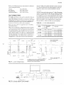
STATIC PRESSURE REGULATOR ACCESSORY
The Static Pressure Regulator must be field installed. Selection of best location and setpomt are the responsibility
y of
the system designer. Refer to Figure 560.20-N2.2 for installation Instructions.
OPERATION OF STATIC PRESSURE CONTROL
When static pressure exceeds the static pressure setting. the
control completes an electrical circuit to the damper motor.
The motor changes the dampers to a position that reduces
the static. Whenthe static reduces to the setpoint of the control, the electrical circuit is broken, stopping the motor In
this new position, A second contact drives the motor In the
oppos]te direction on a decrease in static.
CAUTION: Never operate the umt without installing the
hood or moisture will be drawn into the unit.
x
H
AIR F LOW
-
NO
EXHAUST AIR RAIN HOOD OPTION
?’
The barometr~cexhaust dam~rs, the powered propeller exhaust fan and the damper motor end switch are factory installed and wired as part of the exhaust air option. The rain
hood is shipped in a separate package and must be assembled
to the unit per the assembly instructions in Form 530.25-N1.2
-
m 4
~ -Q
DAMPER
NOTE: The exhaust hood for the DSV 480 is shipped in two
pzckages.
A
HEAD
1
TO
POWER
STATIC ~D.
DUCT ~
0a
o
MOTOR
6
STATIC
PRESSURE
REFERENCE
PRESSURE
CONTROL
OPERATION
D.SV VARIABLE AIR VOLUME
The operation of the D-SV unit can be divided into five
systems.
1, Economizer System (optional).
2. Heating System (optional – used for night setback and
morning warmup only).
3. Cooling System.
4. Exhaust Air (optional).
5. Variable Air Volume Dampers (optional).
GENERAL
Variable air volume (VAV) systems operate on the principle
that space temperature can be maintained by varying the
volume of constant temperature air delivered to the space.
As the space load decreases, air delivered to the space 1spinch12
ed off. The optional variable air volume dampers will then
close to hold a constant duct static pressure. With less air required, both the fan and compressor requ]re less horsepower,
and operating costs are reduced.
The D-SV is a cooling only unit. Electric heat can be added
for use during night setback or morning warmup only. During normal operatmrr the heat is locked out.
The D SV control ISa microprocessor based Honeywell
W7100 dischargeair controller with a discharge air sense].
The control tries to maintain a fixed discharge an temperature by modu]atmg the economizer and sequencing stages
of mechanical cooling. The d!schargeair setting ISflelcladjustable but is set at 55°F by the factory, The control JIS{J
has an adjustable cent ml band. The control band ~djustnwnt
sets a region of ternperat ure centered around the dlschargc
alr set point,
The control energizes or de-energizescoollng stage~Jnd (Jptional economizer to maintain the discharge air (D/A) temperature in the control band.
Central Enwronmental
Systems
—
5
It is recommended that the control band be set as shown:
L
8°F for D SV300
7°F for D .SV360
6°F for D. SV480
The controller has a built in feature which provides a 4 minute off cycle and a 4 minute on cycle to prevent compressor
rapid cycling.
When power fails, the W7100 shuts off all stages of mechanical cooling. When power ~esumes,the economizer will first
be modulated open, prowded enthalpy of the outside air is
suitable. Once the economizer is open, mechanical coofing
is sequenced back on with a minimum of 4 minutes between
succeeding stages, If outside air enthalpy is not suitable, economizer modulation is bypassed, allowing mechanical cooling
to begin sequencing after 4 minutes, with a minimum of 4
minutes between stages.
When the D. SV does not have economizer option, a 510
ohm, ]/4 watt, 570 resistor is placed between termina]s 9
and Y on the W7100 to eliminate the economizer delay and
energize mechanical cooling immediately.
COOLING
b
When the discharge temperature has deviated 1‘F above(or
below) the control band, additional stages of cooling will be
turned on (or off) at four minute intervals until either the
discharge temperature drops (or rises) to within one degree
of the control band, or the discharge temperature falls (or
rises) at a sufficient rate that will insure that discharge temperature will soon be within the control band (about 10 mmutes). The rate feature prevents needless cycling caused by
changesin load. The last stage to be turned on or off is referred to as cycfrngstage.
D- SV units have nominal cooling capacities of 25, 30 and
40 tons. The D SV300 has two stages of capacity achieved
by unloading a single compressor. The D. SV360 has three
sttigesof’capacity achieved by two unloading solenoids on
one compressor. The D SV480 has four stages of capacity
achieved by two compressors each with an unloader.
L
All systems are completely factory assembled, refrigerant
piped, refrigerant charged and leak tested. A strainer drier
and a tno]sture indicator are installed in each liquid line. A
h]gh pressure cutout is located in each system(’s) on the
compressor before the discharge valveand will de-energiie
the compressor control circuit should the system(’s) discharge pressure exceed 395 psig. The pressure cutout wil[
remain de-energizeduntil the system(‘s) pressure returns to
310 ps]g.The opening of the high pressure cutout wdl energize thekwkout circuit. The control circuit must be opened and closed to reset the lockout circuit, AntLcycletltning
is part of the compressor protection module. This prevents
the compressor from lapid short cycling. A low pressule
cutout 1slocated in each system(‘s) on the compressor before the suctmn valveand will de-energl/e the c(~n]plcssor
cent rol circu]t should the system(’s) pressure drop t~~7
psig. This control will automa[ ically rese[ when the suetl<)n
pressure rises to 22 psig. The operung of the low p[essute
cutout will energwe the Iociout CIIwit.
Central Environmental Systems
The control circuit must be opened and closed to reset the
lockout circuit.
Normal sequence of operation is as follows:
1. Power is supplied to the unit through the disconnect
switch. The switch can be field-installed or factoryinstalled as an option.
2. As soon as power is supplied to the unit, the compressor crankcase heaters ITH (and 2TH) will be energized,
CAUTIOIV:Do not attempt to start the compressors wirhout at least 8 hours of crankcaseheat or compressor damage will occur.
3. If the unit is not equipped with a morning warmup thermostat or a day-night switch the 7R relay coil will be
energized. The 7R contact closes energizing the 3M coil.
3M contacts close, starting the supply air fan motor. After an adequate air flow is established, 5 LP closes to energize 6R coil, 6R contact closesin the compressor control circuit. If the unit has a day-night switch the switch
must be in the day position. If the unit has a morning
warmup thermostat it must be sat]sfied or the above fan
and unit operation will not occur.
4. If the D. SV unit does not have an economizer cycle or
if the outdoor enthalpy is too high, on demand , the discharge air sensor will signal the logic panel to close the
“Cool 1“ contacts and energize IR coil.
5. 1R contact closes and energizes IM coil, which starts the
(No. 1) compressor ]n an unloaded condition. At the same
time. 4M is energized to start the condenser fans.
6. If the discharge air temperature is not within 1°F of the
control band the logic panel will energize the following
stages.
a. “Cool 2“ contacts will energize. On the D- SV300 this
energizes the 2R relay. The 2R contacts close de-energizing the compressor urdoadlng solenoid which loads
the compressor. On the D. SV360 t}us energizes the
~R re]uy, The 2R contacts close de-energii.ingthe compressor unloading solenoid which loads the compressor
to 2/3 or full capacity. On the D. SV480 this de-energi/es the compressor unloading solenoid which loads
t}leNo. 1 compressor.
b.
“COO13“ contacts will energize. On the D..SV36Othis
de-energizesthe compressor unloading solenoid which
Iodds the compressor to full cap~ctty. On the D .SV480
this enclgizes the 2R relay. The 2R conlacts close and
energize 2M COIIwhich starts the No. 2 c~~mpressorin
an unk}.ided condition.
c, “COO!4“ contacts will energize. On the D. SV480 this
de-energues the ct~mpressorunloadlng solenold winch
l(xidsthe No 2 compressor.
7, The u(~mpressorshort cycle time and low vt)ltage p]otectmn ISp~rt of [he solid stdte compressor prot ec~lon m[~dule. It plevents J compress(~[fr(~mstarting unless It has
13
m
e
m
c
p
a
m
s
o
1
1
C
d
2
D
and condenser fans No. 3 and 4 on the D. SV360 and D. SV480 WI]] be de-energ]zed by 2TH. ( Refer
to Table 5.)
ENT THERMOSTAT
t
e
m
LINKAGE
ADJUSTMENT
SETTING
~
~
*
f
w
F
r
f
ECONOMIZER
E
dt
l
c
Turn the rninlmum
outdoor alr pos]t
d
A
(
-
E
M
mr adjustor to the 100’/
t
I
E
(p
-
p
whenever the outdoor
i
d
outdoor
All
R
a
I
If’ not,
loosen the drive rod bolt
c
stage t~f’ c[mling
y
au is cool and dry
The
m
n
?
m
blades ~hould
be full}’ closed.
hnkdge connecting (1ICoutdoor-” air
Jnd the return ti]r dampers must rm)ve freely.
a
a
e
u
p
d
r
SYSTEM
1. Outdoor
Return the nun]mum outd(mr alr tid]u$tor to the 100’%
outdtwr ar[ p~)sltl~lrl irnd check for co mpletc f’reeck)rn 01”
hnkage movement JS the ret urn ~lr Lfarnpel J CI(JW.
d
o
a
The rnlnimum outdoor atr adIn the top of the damper motor
juster is factory mounted
e
(
t
h
limit t}le introduction
the corrt rol will not
during high humidity
During
t
higher ambient.
mg so as tt]
of outdoor air. As noted in
allow outduor ~]r to enter the unit
a
condit
dry condltlons, alr IS Int reduced ut o
R
H
%
CONTROL
4F
I
C
c
I
D ~
78
I
73
68
69
63
64
]
c
(
ure on the cool \Id12rf the cooling IS “free”
e
SYSTEM
A ,gJsor elect r]c Iled t lrlg wet ]{)n 1>{)j fc rc d ti~ J I .Ic[or~ n
option, Refc r to t}le }mtite r ]rl ~tr uctlon for :IddI [ror)J] In!~)rln.itlt)rl.
1
Form 530 25-N 19
]
The beat on a D. SV unit WI]] unlv operJte when the unit
rs lrl the nlgllt mode of i)perirtion or during the rm)rnlr]g
wwrnup nmie. During nigbt jet b~ck t }]e heat wi II cycle I)t f
c~f’J sepsnrt c he~t Ing t Ile rmflstat. During r]l[)rnmg warmup
the heat is energwedb} (he rm)rnrng wtir rnup thermostat,
During un) heatrng mode of” i)per.it]t)n tile tiIIflow (Ipera{es
J1 fll ii !lOW
58
Al R VOLUME
b
t
M,n
——
T
p
e
HEATING
(~utdo~~r air tidlustor f 01 the rnmlmum
r
(SET POINT “B”)
E
A
C
I
v
Optron
P
M
Set the nunlmum
(Jaj [ Icdt Option
TABLE 6 – ENTHALPY
If
ut
1
U
D
D
!
m
t
DAMPER
TABLE 5 –AMBl
a
a
2
d
}IIg}I
c
p
1
c
(p
c
f
f{]l
7 hc Ilr VI,llIme
CONTROL
—.
SYSTEM
S} stcIo ~t]nji>tj
ot
1 DJIIIpC Is.Alr Volume Co]]tr(]l. (ftiuloly
l
1 Col]troji
opt]on )
O
C
E
S
5
-
As the air quantity required by the VAV outlet boxes decreases, the static pressure in the duct system increases.
Optional modulating dampers can be ordered with the urut
to provide a constant static pressure in the duct system at
all flow conditions. The optional air volume dampers are
controlled by the accessory static pressure regulator that
is located in the conditioned space. As the duct static pressure increases above the set point, the static pressure control will modulate the air volume dampers to maintain the
static pressure setpoint.
cuit between terminals 60 and 64 of terminal block 2TB or
automat ically by an end switch on the economizer damper
motor. As the economizer damper opens, it closes the end
switch on the damper motor and turns on the exhaust air
fans. The degree of blade opening at which the exhaust fans
are energi~ed can be adjusted by the following procedure.
Refer to Figures 13 and 14.
The static pressure regulator has a range of 0.01 to 6.0
inches of water column with a differential adjustment of
0.05 to 0.75 inches. The static pressure regulator is field
connected to a terminal block in unit main control box.
2. Loosen the thumb nut and the cam locking screws.
1. Use the black scale plate as an indicator of motor position
for switch operation.
3. Set the operational and differential cams.
4. Check switch adjustment by movingthe adiustor 2RH to
move the motor. Switch should clic~ when-desired make
and break points are lined up with index mark and the
exhaust fan should start and stop.
J
CHECKING LINKAGE ON Al R VOLUME DAMPERS
After power has been supplied to the unit, the air volume
dampers should be checked to make sure they operate freely and open/close properly. It may be necessary for the installer to adjust the linkage between the damper motor and
the blades due to loosening in shipment.
CHECKOUT PROCEDURE
After electrical power is connected to the unit, the operation of the air volume dampers, damper motor, etc. can be
checked.
-
WARNING: 1.?0volt power is connected to the switch.
5. Tighten thumb nut.
CAUTION: Do not attempt to turn the motor shaft by hand
or with a wrench as damage to the gear train
wi[l resull.
The damper motor has electric wire leads. Wires“BI”,
“W1” & “R1” can be jumpered to cause the air volume
damper motor to drive to the open position or the close
position. The dampers and linkage should be checked for
position and linkage should be checked to insure linkage is
adjusted properly and tight with “open” and “closed”
dampers.
OPERA TCOMAL
c’”~
3
DIFFERENTIAL
CAM
1. Open Dampers - Jumper terminals “R1” and “WI” on
damper motor.
2. Closed Dampers – Jumper terminals “RI” and “BI” on
damper motor.
“
TWJMBNUT
SCALEPLATE
‘*
!“
3
,
.
SLOT
IN JI ‘—
d
SCALE
LOCK
EXHAUST AIR SYSTEM
The exhaust air fans are energized by manually closing a cir-
@
A
@,,,
STARTING POSITION
OPERATIONAL
FIG. 13 – INTERNAL VIEW OF DAMPER MOTOR
END SWITCH
@
CAM
CAM
ROLLER
SWITCH,
CAM
INDEX
INOEX
INDEX
SET DIFFERENTIAL
(d d,s,rod)
IAL
7MENT
ONAL
AM
REw
ALEPLATE
ALIGN ZERO POINT ON DESIRED SCALE
OPPOSITE INOEX MARK
LOCATE DESIRED SWITCH MAKE POINT ON
5CALEPLATE ANO ALIGN wITH INDEX
MARK TURN OPERATIONAL CAM UNTIL
ROLLER IS ON POINT OF uPPER CAM LOOE
TIGHTEN OPERATIONAL CAM SCREW
FIG. 14 – ADJUSTING DAMPER MOTOR END SWITCH
Central
Environmental
Systems
SCREW
15
5
SUPPLY A Rl BLOWER ADJUSTMENT
required maximum
the static resisttincesof
RPN1
fIL)m
the
4.
tenslm m ead belt shrll be adjusted PM the folprocedure. See
optllms, and
(
J,
hl(lwt’r
b
-
t
(
t
d
a
e
(r
t
o
af
$
A
M
t
1
}
It
ti
u
tu
a s r
a
After
as
n
If
BELT
SECTION
“B”
“c”
a
Note
1.
DEFLECTION
FORCE (LBS.)
——
MAXIMUM
MINIMuM
4
5
14
11
M
e
Table I
t
7
-.
4
Both movable fhnges on a
f
TABLE 7 – SUPPLY AIR SYSTEM ADJUSTMENT
MODEL
RPM
10 T-m
TURNS
7-1/r
I OPEN’ 1---
,
. —
=-~..:.
DSV360
3
2
20
“
L
-=2=
-,:.+
.%
—g..
—
&
—
1038 ~
876
908 ~1076 I
L
‘
–
–
‘
(
t
(c)“
(x)
FIG. 1 –5 TYPI CAL MOTOR MOUNTING ASSEMBLY
2
”
1
C
E
S
530.25-N2
After the pre-start check list has been completed:
CAUTION. If this method is used, the holes must be sealed
with dot plugs (P/N 029-13880) or equivalent
to prevent moisture from leaking into the unit.
1. Start the supply air blowers,
L
-)
.
Adjust the resistances in both the supply and the return
duct systems to balance the air distribution throughout
the conditioned space. The job specifications may require that this balancing be done by someone other than
the equipment installer.
To check the supply alr CFMafter the initial balancing has
been completed:
I
1
1. Drl[l two 5/16“ holes (A & B) as shown in Figure 16.
)
2. Install two 1/4” O.D. tubes, one between the filters and
the air entering side of the evaporator coil and one between the supply air blower(s) and the air leavingside
of the evaporator coil.
,
1
‘ DIA.
—
80
;0
5{16“
DIA.
MODE L
J
DSV300
B
o
DSV360
DSV480
\
=
UNIT
DRAIN
[
80
8000
9600
12800
43
1;0
160
PERCENT NOMINAL CFM
1;0
% OF NOMINAL CFM
100
90
I 110
C.F .M.
11000
10000
I 9000
13200
10800
12000
17600
16000
I 14400
1;0
120
12000
14400
19200
FIG. 17 – PRESSUREDROP ACROSSA DRY
EVAPORATOR COl L VS SUPPLY AIR CFM
—
—
RIGHT END
VIEW
—
30’’---
+––
-33”
—
FIG. 16 – HOLE LOCATIONSFOR SUPPLY AIR
CFM CHECK
NOTh”: To get a proper staric pressurereading, [he sensing
tubes should (A) be inserted through the rear or
condensate drain side of
the unit (B) be located
approximately 6 inches away from the coil surface
and as close to the center of the coil height as possible (C) extend into the unit approxiwutely 12
inches.
3, Make sure thfit the access panels [or both the suppl} mr
blower motor findt be filters ~le secured. These panels do
not hove to be secuJeclwherr the 1/4 ]nch tubes entel
the units because the blowel and falter compartments
operate at a negative pressure.
L
4, Make sure that the tube openings are perpend]cu]ar to the
Iir tltnv so that vekrcity pressure will not affect the statIc
pressure reurilngs.
Cerltral Environmental Systems
5. Usingan inclined manometer, determine the pressure drop
across a dry evaporator coil. Since the moisture on an evaporator coil may vary greatly, measuring the pressure drop
across a wet coil under field conditions would be inaccurate,
NOTE: Disconnect the compressors befhre taking an,v test
measurements to assure a drv evaporator coil.
6. Knowing the pressure drop across a dry coil, the actual
CFM through the unit can be determined from the curve
in Figure 17.
,~rOTk-. On D SVun[ts a[iau- LwhitHedampers ih unit and
termitlal bc)xesill du(t s)’stem nwst be c>penwhen
checkitlg air quattti[>’,
If the CFM ISabove or below the specified value, the supply
air motor pulley may have to be readjusted, Alter one hour
of operation, check all belts and pulleys for t]ghtness and
alignment.
WAR,VI,}’G.Failure to properly adjtist the total system CFM
can result in extensive blower damage.
17
5
3
0
.
2
5
-
N
2
Two jumper plugs, one red and one white, are located at the
top of the board. When they are removed and replaced with
the connectors of the serviceanalyzer, the analyzer will override the dischargeair control. AHsystem functions such as
heating, cooling, economizer, and night set-back can be slmulated. Malfunction indicator lights are provided to determme which system has malfunctioned,
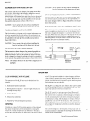
MASTER PRINTED CIRCUIT BOARD & PLUG-IN
RELAY ASSEMBLY
AUof the control reltiys that are required for unit operatmn
are mounted on the printed circuit board. Figure 9 shows
this assembly which is located In the main control panel. All
of the relays are of the plug-invariety, no wiring connections
have to be removed to replace a relay. Since the relays are
transparent, the mechanical contact switching can be observed for easier electrical troubleshooting.
CAUTION: Whenremoving the connectors of the service
analyzer, the two lumper plugs (one red and one
white) must be reinstalled into their proper sockets before the s,vstem canfunction.
The low voltage field wiring is to be connected along the top
of the printed circuit board at the eyelet connections. Each
terminal ISmarked both numerically and with letters correspmding to the set-back heating thermostat for easier mstallat ion.
The procedure for troubleshooting a unit with a serviceanalyzer connected to its printed circuit board is outlined below.
tors from the field service module connections located at
the top of the printed circuit board by squeezing the releases on the sides of the plug. Remove wire 119G from
the PCB,
SERVICE ANALYZER
The analyzer allows complete over-ride control of room
thermostat from the units Printed Circuit Board located
withrn the control box of the unit. From this posltlon, the
user can operate the system in coo[ing, heating, fan or economizer operation.
Make the following connections:
1. Prior to connecting the Service Analyzer, disconnect
power to the umt (high voltage),
2. Remove the red and white, 12-wire,jumper plug connec-
3. Install the female portion of the 12-wirered analyzer
plug into the red module connection and the white analyzer plug into the white module connection of the printed circuit board. See Table 8.
NOTE’ Make sure that all switches on the service analvzer
are in the “OFF”position prior to supplying power
to the unit.
TABLE 8 – SERVICE ANALYZER FUNCTIONCHART
I
SWITCH POSITION
St 1
Econ
Auto
NSE
Auto
St 2
Econ
On
ST 1
ST 2
HEAT
HEAT
off
off
G
On
St 1
LIGHTS
—
==-1=1=
COOL FAN
off
PROPER
ST 1
COOL
ST 2
COOL
ECON
off
off
ON
FAN
OPERATION
Fan on, O S A.
T
dampers
+
—.
.—
off
off
off
0;”
-
On
operate
tu setting of
ml xed alr control.
On
Fan on, Compr
#f
on, O S A. dampers
t
operate
to sett{ng
of
m{ xed a)r control
St 1
Cpr
Compr
~oT4-of,-
2nd Stage
Auto
off
off
Auto
On
off
Auto
On
I i---
——
Night Setbac~
(cool )
Nqht
St 1
St 2
-off
Heat
2nd Stage
cool
1
‘-1
Setback
-
Heat
St 1
St 2
(heat)
t
18
off
St 1
St 2
off
On
off
on
off
off --1
off
‘On
On
off
–
On
Co=
off
O;f
On
off
off
-1
,2,
O S A
dampers open to
mln pos(t[on
of{
off
On
Heat
seitlo-n
operates
r{,duced
off
– , - On
On
Auto
Fan,
run w)th
~
I
##l
O S A
dampers open to
mjn poslt(on
1
Auto
Fan & Compr
on, w[th
~
~
Heat
T off
On
-St 1
St 2
Cpr
Heat
sectuon o~er
ates full
on
on
capacl,y
c<ipac)ty
No ~ool lng, econ
on
or fan opera tnon
Cpr
off
Iiutll
-
011
Heat
On
& fan only
operdte
r---
from
N S B Thermostat
Central
Envlronmcntal
Syslems
-
530.25-N2
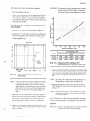
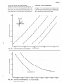
FIXED OUTDOOR Al R ADJUSTMENT
To adjust the amount of fixed outdoor au, see Figure 18. Locate the amouni of outdoor air required and the return duct
static on the chart to determine the position in which to set
the blades, The blades can be adjusted by varying the position
of the adjustment arm on the left side of the fixed outdoor
air damper.
EXHAUST AIR PERFORMANCE
See Figure 19 for the performance of the exhaust air fans.
Locate the amount of return duct static on the left hand
side of the chart. The amount of air which will be exhausted can be read from the bottom of the chart.
o
BLADE
POSITION
Q
w
m
~
v
0
0
0
I
0
I
.,
0
.
L
\
B
1
c
+
FIG, 18
–
lb
io
FIXED OUTDOOR AIR ADJUSTMENT
\
io
40
50
‘%OUTDOOR AIR
I
0.5
\:
..
0.4
\
0,3
,
0,2
‘\lh=
1
!
.
.
t
DSV480 UNIT
OSV300/360’ UN ITS
01
,
3000
4000
5000
,
6000
EXHAUST
7000
AIR CFM
8000
9000
10000
11000
FIG. 19 – EXHAUSTAIR PERFORMANCE– ALL FANS RUNNING
Central Enwronmental Systems
19
530.25-N2
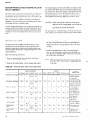
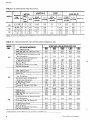
TABLE 9 –BLOWER
MOTOR AND DRIVE
DATA
h
MODEL
, DSV
300
360
480
NOTE
●2O
i3L0WER*
913-1098
1025.1210
780-940
7.5
10
10
1.15
1.15
1 15
924.1114
15
1.15
213T
215T
215T
254T
924-1114
1190
15
20
1.15
1.15
254T
256T
are 1750
has a f!xed
RPM,
motor
*
,~:[:$
49-5.9
1-3/8
1-3/8
1-3/8
1-5/8
5.5-65
4.9.5.9
5.8.7.0
5.8-7.0
7.2’
solid bases, and require
11
10.6
starters
UPTON OR ACCESSORY
G560 Gas Heat
G800 Gas Heat
E040, 060, 080, 100, 120 Electric Heat
Exhaust Air
Economizer Return Air Damper for End
Duct Connections
Economizer Return Air Damper for
Bottom Duct Connections
2“ 30’% Efficient Filtersl
Bag Type Filtersl
Discharge Air Dampers ( Ful Iy Open)
—
End Duct Connections
20
tnclude
Add these resistance
overloads,
which
1.7/1 6
1-7/16
1.1 5/1 6
1-1 5/16
588
58,8
63.8
63,8
1-1 5/16
1-1 5/16
63.8
62.9
are factory
B57
2
2
B57
B62
B62
B62
2
2
2
C60
2
supplled
a deduction
for 2“ throwaway
values to the available
static
0.02
0.02
0.01
0,01
0.02
0.12
0.15
0.03
0.02
0.03
0.19
0.23
0.28
0.10
0.02
0.13
0.12
0.02
0.16
0.07
0.08
0.01
0.01
0.01
0.07
0.09
0.11
0.17
021
9600
0.13
10800
0.16
12000
0.02
0.01
0.02
0.03
0.02
0.03
0.03
0.02
0.03
0.04
0.02
0.04
0.05
0.03
0.05
0.18
0.23
0.28
0.34
0.40
0,08
0.01
0.06
0.10
0,12
0.01
0.07
0.14
002
0.11
0.35
—---—.
0.27
17600
0.07
0.10
0.05
0.17
0.02
0.13
0.40
0.32
19200
0.09
0.12
0.06
--
0.25
030
0.19 –
13200
0.23
14400
0.14
12800
0.04
0.05
0.03
0.24
0.18
14400
0.05
0,06
0.03
0.01
0.09
0.30
0.22
16000
0.06
0.08
0.04
0.03
0.04
0.05
0.06
0.07
0,13
0.16
0,19
0.23
0.10
0.12
0.02
0.14
0.410.49
0.14
0.02
0.16
O 48
0.62
0.10
0.06
0.01
0.08
0.24
0.25
shown
0.02
0.03
0.02
0.03
0.06
0.19
or cleanable
precsure
0.01
0.01
0.01
0.13
0.10
I
(IWG)
I?E8WT’ANCE{\WG)@C)ESHN4ATED
,&FM
Ilo@o
10000
12000
I-
E040, 060, 080, 100, 120 Electric Heat
Exhaust Air
Economizer Return Air Damper for End
Duct Connections
Economizer Return Air Damper for
Bottom Duct Connections
2“ 30% Efficient Filtersl
Bag Type Filters’
Discharge Air Dampers ( Fully Open)
End Duct Connections
1 These resistances
D
with
FOR UNIT OPTIONS AND ACCESSORIES
G400, G560 Gas Heat
480
11
1-5/8
End Duct Connection
360
9.4
9.4
11
1-5/8
G400, G560 Gas Heat
E@IO, 060, 080, 100, 120 Electric Heat
Exhaust Air
Economizer Return Air Damper for End
Duct Connections
Economizer Return Air Damper for
Bottom Duct Connections
2“ 30% Efficient Filtersl
Bag Type Filtersl
Discharge Alr Dampers ( Fully Open)
300
1 BLOWER PULLEY
I
PITCH
OORE
DfAMETER,
INCHES
INCHES
pulley
TABLE 10 –RESISTANCES
Mom%. ,
have
FIXED
ADJl$TABLE
1, M0T(3F?PULLEY
PITCH
HP VICE FRAME
~,*E DIAMETER,
FACfNcHEs
T(3R
J&
All motors
HP drive
f@TOfW
~R .
I
0.08
0.01
0.10
0.01
0.12
035
0.39
0.30
0.31
–
fl Iters
(n blower
perforrm~nce
data table
Central
Enwronment,+l
Systen)s
-
530.25-N2
TABLE 11– SUPPLY AIR BLOWER PERFORMANCE *
MODEL DSV300
915’
950
1000
10252
1050
11003
1150
1200
12104
1250
0.84
1.08
1.30
141
1 52
1,75
1.98
221
2.25
2.44
4.17
4.47
4.92
5.15
5.40
5.91
6.43
6.97
7,08
7,53
3.86
4.11
4.47
4.65
4.85
5.25
5.67
6.12
6.20
6.59
0.67
0.82
1.05
1.17
1.29
1.53
1,77
2.01
2.06
2.28
4.82
5.17
5.66
5.92
6.18
6.72
7.28
7.85
7.96
8.43
‘ Mlnlmum speed for the 7 1/2 HP motor option
2 Mlnlmum speed for the 10 HP motor ormon
4.41
4.67
5.06
5.26
5.48
5.92
6.38
6.88
6.97
7.36
0,35
0.50
0.74
0.86
0.99
1.25
1.51
1.78
*.83
2.05
5.54
5.91
6.45
6.73
7,02
7.61
8.23
8.8s
9.01
9.55
—
4.95
5.26
5.70
5.93
6.17
6.67
7.20
7.76
7.87
8.35
0.15
0.40
0.53
0.66
0.83
1.20
1.47
1.53
1.7!3
—
—
6.64
7.26
7.57
7.90
8.66
9.24
9.94
10.08
10.66
5.86
6.37
6.63
6.91
7.48
8.07
8.66
8.79
9.30
3 Maximum speed for the 7 112 HP motor option
a Max)mum speed for the 10 HP motor opt!on
—
—
—
.
—
—
0.;3
0.27
0.56
0.83
1.11
8.63
8.85
9.52
10.25
11.02
!1.19
—
$.17
-
—
U71L?HPmomr
~V3HPmotor
7.4!5
7.74
8.33
8.95
9.69
9.75
—
MODEL DSV360
780
800
850
800
9252
9403
950
1000
1050
1100
11154
1150
1200
095
1.17
1.41
154
1.62
1.67
1.84
222
2.50
258
278
306
4.48
4.70
528
5.89
6.20
6.40
6.53
7.20
7.90
8.63
8,86
9.40
10.21
4.01
4.28
4.74
5.23
5.49
5.62
5.76
6.33
6.92
7.54
7.74
8.20
8.90
0.76
1.00
1.25
1.38
1.47
1.52
1.80
2.08
2.36
2.44
2.64
2.92
544
6.07
6.73
7.07
7.28
7.42
8.14
8.89
9.67
9.91
fo 49
11.35
4.88
5.39
5.94
6.31
6.38
6.51
7.11
7.76
8.43
8.63
9.15
9.90
0.37
0.47
0.73
1.00
1,14
1.23
1 28
1.57
1.86
2.16
2.25
2.46
2.76
5.89
6.15
6.85
7.58
7.95
8.18
8,34
9.13
9.95
10.80
11.06
11.69
12.62
5.45
6.02
6.63
6,95
7.15
728
7.96
8.67
9.42
9.64
lo.m
11.02
0.07
0.17
043
0.71
0.85
094
1 00
1.30
1.61
1.92
2.02
2.24
2.57
5.83
6.06
6.70
7.39
7.75
7.96
8.12
8.88
9.68
10.53
10.80
11.42
12.36
—
—
—
—
—
—
0.08
0.36
0.51
0.60
0.66
0s6
1.28
1.60
1.70
1.94
2.29
8.44
9.31
9.76
10.03
10.22
11.17
12.16
13.19
13,51
14.27
76.40
7.38
8.13
8.52
8.74
8.91
9.74
10.63
11.55
11.83
12.50
13.48
—
3 Maximum speed for the 10 HP motor opt(on
4 Maximum speed for the 15 HP motor option
I M(mmurn speed for the 10 HP motor option
2 M!nlmum speed for the 15 HP motor opt)on
6.61
6.90
7.66
8.46
8.87
9.13
9.30
10.18
11.10
12.06
12.35
13.06
14.10
m
IO HPmomr
U
15 HP ”otor
MODEL DSV460
925’
950
1000
1050
1100
11 15=
1150
11903
1200
1 29
144
1 74
204
235
244
267
2.92
299
9.22
9.66
10.56
11 50
12.49
12.80
13.53
14.40
14,63
8.07
8.45
9.24
10.06
1093
11.20
11.84
12.60
1280
0.91
1.06
1.36
1.69
2.02
2.12
2,36
2.63
2.70
1056
11.01
11.94
12.91
13.93
14.24
15.00
15.89
16.13
9,24
9.63
1045
11.30
12.19
12.46
13.13
13.90
14.11
0.43
059
0.90
1.24
1,58
1.68
1.93
2.21
2.28
12.35
12.82
13,78
14.78
15.83
16.15
16.93
17.85
18.09
10.81
11.22
12.06
12.93
13.85
14.13
14.81
15.62
15.83
—
—
—
0.07
0.39
0.74
1.09
1.20
1.45
1.74
1.81
14.47
15.45
16.47
17.64
17.88
18.88
19.59
19.84
1266
13.52
14.41
15.35
1S.63
16.33
17,14
17.36
—
—
—
—
—
—
—
0.27
0.53
0.64
0.90
1.19
1,27
18.45
19.51
19.84
20.64
21.68
21.84
16.14
17.07
17.36
18.06
18.88
19.11
‘ Mlnlmum speed for the 15 HP motor opllon
2 Max(mum speed for the 15 HP motor option
3 Speed for the !nonadjustable drive of the 20 HP motor opt!on
Central Environmental Systems
a15HPmotor
n
‘20 HPmotcIr
21
530.25-N2
START-UP
PRE START-UP CHECKS
WARiVING
Jttmper )tire ‘“J21“,(rejer to Elementar]
WlrltlgDlagrat?l),was intentionaiiv dk’Otlnected atd taped at the factory. This is
done to pre~tentblower motor operati(m
and cotnpressoroperation before proper
pre start-up steps hz~e been performed
Do not connect “J21“or complete installation ofdav-night switch “12-SW”to
terminal 119 until pr? start-up steps
have been perj)rtned.
PRE-START STEPSAND PROCEDURES:
Before starting the unit the following check hst should be
completed:
Addltwnal Information regardinginstallat [on and adjustment of the statICpressure regulator accessory is provided
m the ~ccessory instruction Form 530.25-N2. 1.
CAUTIOA’, Do not start the utl[t blower utl[il the VA V
ducts-r’stctnsupp~IIav boxes hale been
opened. A d]ust the dl~ctair boxes [o the
]~l!~’OPCtIp~)$ition,usi!lgthe box thermostats,
5. Make sure the proper clearfinceswere considered.
6. Make sure all foreign matter has been removed from the Interior of the unit (took, construction or shlpplng materta1s),
7. Rotate all fans and blower wheels manu:illyt<]check f(]r free
rotation.
8. Check belt tensions and alignment.
1. Make sure the available power supply and unit nameplate data agree.
9.
Make sure all w]ringconnect lorrsare t Ight,
2. Make sure all air filters are properly installed in filter
racks.
3. rum on power to unit:
If a disconnect switch N installed outside the unit, turn
it to ‘<ON”.The non-fused disconnect (optional) located
in the unit’s mam supply panel must also be turned “ON”.
10.
Makesure the fuse sl~esand the power wire tire properly
sl~ed,
CAUTION: Do not attetnpt to start the compressors )\tlt}lout at least 8 hours of crankcase heat or compressor damage will occur,
4. Check operutlon of the varmus d~]mpers}’stems:
a. Air volume dampers - refer to paragraph on “Au
Volume Dampers” – (“Air Volume Control System”).
11 Make sure all controls are set at theu proper set points.
12 Make sure condensate dra]n line IStr~pped per irlstructlons
as mdlcated with Fitzure4.
13. For shipping, the compressor hold-down nuts are
tightened, drawing the mounting feet down to the
shipping stops. After the unit is in its final position,
the four hold-down nuts must be removed to insert
the rubber grommets found in the small parts bag.
Replace the hold-down nuts and tighten until they
start to compress the isolator springs and then give
them an additional half turn.
NOTE: Stop air twlume dampers in “open”position.
b. Economizer dampers - refer to paragraph on “Economizer System” – (“Damper Linkage Adjustment”).
c, Exhaust air system - refer to paragraph on “Exhaust
Air System”.
WARNING: it is important that all panels at? ji~lo”secured with htches and screws beji)re tinit is
started.
Be sure that the ~taticpressure control accessory is installed at~dread>’to reguhte
the static pressure in the duct s?’stern,before starting the tinit blower.
22
Central Environmental Systems
530.25-N2
INITIAL START-UP CHECKS
WAR,%rING:
Besureair volume dampersareo~en and unit mm.
els are secured. Check [o be sure that builditrg
VA F’supply air boxes are open and that crankcaseheaters have been on for at [east8 hours.
1 To st~rt blower and compressor connect the loose end of
jumper “J21” to transformer “2T” in the main control
box. Jumper “J21” 1smarked with a red tag, If the daynjght accessory swltch “12-SW”is used; closing the “day”
cvrcuitbetween terminals 119 and 133 will start the unit.
NOTE: Whena &y-night sw”tch“12-SW”is used, remove and discardjumper “J21”,
Check 3 phase blower motor rotation. If rotation is incorrect, reverse any two leads on the motor.
2. Check the dial settings on W7100 discharge air control
m main control box. The ln]tial factory settings are:
a. Set point – 55°F
b, Control band – 8°F
c. Reset ~ Not apphcable to York unit.
NOTE: Cbtr~ii[ts~s[em desigrwrfor more detailed information regardingthe above setpoints.
3. The proper supply air CFM should be established at this
time with an Inclined manometer as outhned m this lnstructmn. This 1san important part of the start-up procedure since it directly affects nuisance trip-outs on unit
safety controls, condensate water blow-off from the evaporator COII, bearing and shaft damage, noise and vlbration.
4. With an ammeter, check the compressor and the supply
alr blower amps to make sure they agree with the umt
dota plate.
5. After approxrmate]y 15 rn]nutesof operation, check the
hquid hne sight gl~ssesfor t propel IIqurd tefrIgerant seal
lo e~ch of the refrigerant circuit.
6. Refer to the heatrng Instruction for the correct heatmg
sequence of operat mn.
-1
,, in corrjunction wrtb the HVACsystem des~gner,pneun]atlc control contractor and qual[fwd VAV balancing technlclan, the varrablcalr volume system must be balanced
t<)meet the budders speclficatlons,
Only qualrfmdand trained personnel that are knowledgeable on VAV system balancing should balance or supervrsebalaricingof the VAV system.
The urrlt stat[c pre~surecontrt~lmust be ~djustcd to meet
[he VAV ~ystemrequirements. Adjustment (>fthe blower
motor valIable pitch pulle},may also be requrred t~~meet
VAV system requuements.
Central Enwronmental Systems
All other requirements specified by the variable air volume
system designer must be satisfied during unit start-up and
VAV system balancing phases.
Proper testing and balancing not only insure that HVAC
systems meet design and comfort requirements but also
saveenergy, cut operating costs and reduce maintenance
requirements.
SAFETY AND SERVICE FEATURES
The control circuit includes the following safety features:
1. The supply air blower motor is protected with manual
reset starter overload protectors.
2. The condenser fan motors have inherent protection with
automat]c reset.
3, The primary winding of transformer IT is protected by
fuse 12FU. The secondary wmdmg and the 115 volt control cucuit are protected by fuse 13FU.
4, All safety controls in the 115 volt circuit have the “return” or “common” side of the 1T transformer grounded.
Fuse 13FU will “BLOW” whenever a dangerous condit]on
occurs. The unit casing Malso grounded.
5, The wuing to each compressor motor, each condenser fan
motor and the supply atr blower motor are individually
fused according to the National Electrical Standards.
6. The compressor(s) are protected by a 100 watt immersion type crankcase heater(s). Heater(s) are energized
whenever power is supplied to the unit. When the compressor(s) are energized, the heater(s) are turned off,
CAUTION: Do not attempt to start the compressors without at least 8 hours of crankcaseheat or compressor damage will occur,
7. Each refrigeration system has a low pressure cutout ( 1LP
for system No. 1 and 2LP for system No. 2) to shut down
the compressor due to loss of reirlgerant charge or a build
up of frozen condensate on the compressor before the suction valveand are set to open when the suction pressure
drops to 7 pslg. These controls wdl automatlcal]y reset
when the suction pressures rise to 22 pslg. The opening of
the low pressure cutouts WIII:ictivate the lockout circuit.
8 H]ghpressure cutouts ( 1HP for system No, 1 and 2HP for
system No. 2) are located tn each system on the compressor
before the drschargevalve. Should a system discharge pressure exceed 398 psrg,the cent rol wdl open and de-energize
the compressor. The pressure cutout wrll close when the
dlwharge pressure drops to 310 psig, The opening of the
high pressure cutou[ WIII activate the lockout clrcult. The
high pressure cutouts may open due (o a dirty or restricted
condenser COII, 10SSof a[r flow or too h@r an amb]ent alr
temperature.
23
9
The Icrckou[ctrcults mcntloned fiboveWIIInot be er]erg]led
during normal opera( ion bccausc they have a h@r rcs[sttincc
The flow of clectrlclt y wrll norrnalty follow the pa[tl of
least rcststancc
through [hc compressor
contactor~
I M and
2M. 11, however. ~ low or high pressure cu [out upcns, [hc
lockout
reltiy 10R ur I I R WIII bc cnetgvcd.
S]nce tile voltage across 10R or I 1R will exceed
I WV, the vOI t+y ucrt)js
I M or 2M WIII be too low to pull rn the contractors The normally closed con tticts of’ 10R or 1JR wrll open the clrcult In
serie$ wlt h Ihc low or high pressure cutout. When Ihcsc ~on-
tacts sutomat IcullyCIOSC.
the lockout
mtcrru p[lng t hc p(lwcr
TWLI adv~ntages
a.
prevents
crrcu] t c~n be rcwt
rirpld cycling
by thl~ circuit:
of the compressors
which
LJn be
LftimJglng
b. Ttw alternate usc of manual reset cutoffs
bicm above bu[ may rcqu[rc an cxpcnslvc
reset these corrt rolj.
avotds the prt)serv]ce call (o
10.
Free/c~tot
Il.
The supply tilr flow must be prcrvcn by vacuum switch 5LP
In the event the belts on the supply air motor break C)I the
WIpply alr motor shoulcf bc rlc-encrgl/ed by lt~ overload pr<)tector~, 5 LP wrll open and interrupt the cooling. heatlllg
and eccrnomrzer control c ]rcults. This assures that the \ ar IOUS
.3T11senses the su~tlon temperature 01 [he No I
~ystcrn IIId WIli shu I down Lmprcssor(s)
when IIIIS [cmpcrature drop~ to 32 ‘F. It will reset autcrrnat[caily at 37’F.
modes of operat Ion do not cent mue without proper air tlow
la
The
compressor
1 !vlP, 2MP
rncrtor protcctcrr(s).
WIIIin(crrupt
the conl~;ressorcontrol “circuitwhen sensingan ovcrlotid co’nditton.
Also an anti-recycle
tlrncr
comprc~w~r f mm rapid uycl Ing. T hc cwmprcssor
will
for five m]nutes. I t alw monltcrrs the vol tagc of the
I zo volt control crrcuit and WIII shut down the compressor
lt
the
voltage
drops
below 85 + 4.5 volts.
13 011 preswrrc control swl[chcs arc mstallcd In the cwnlptc~wr
circuits. These assure that adequate otl pressure IS prcwnt t o
I ~ pre$$urc! IS
! ubriCa[e thC I]]ov[ng parts L)lthe compressor.
no[ adeq ua tc, Ihc sw Itch opens
It lt manually reset.
hut
t Ing down
-
the COIIIprewr.
by
to the unit.
are gained
vent the
stay off
IS part of this Lfcvlce 10 pre-
l-l When the putnpdown acccsx)r~. Model 2PD04700 101. I\
installed, the co rnpre$w)r will IJ)nt Inuc to opcrat c through
~t)llta ct 12TR-2 after the r[x)rn thcrm[) SIat or cent rol]el IS
wt Isfle d. Solenoid 3S0 L In the IlquIrl Ilne I; now cI()~ecl
and the ~{1nlpre~~or pumps most of the rcfrigcra nt OUt of”
the ev:iportitor” to the h~gh side <)ftbc ~ys~cn), TIIe ~>stcm
su~(]on pre~sure dt op~ untl] the low pre~sure cutoff ( 1LP)
IIpens, This wit I Sh U[ d{)wn the co mprcs~t)r and r.fc-cner,gI/c> the 12TR ICIJ} wbIch opcn~ 12TR-2 to put the opetatlon of the ~omprcw)r under the contr 01 of tl~c 1R rcla}
41s{) present ISJ 12TR- 1 cent.ict which IS clowd when the
\ySte Jn 1$ off J lld prOV]de S 2 b} pdss cu cU1[to aI]()~’(,011
[8~’tor~ 1kl ~nd 2M to bc uctr; Jtcd In the event the kIw pIcJ>UIc CU10 ut hti~ not rc$ct. }f’rthout t hls pu mpdowrn clrcult,
It IS powble to h~~e t hc 011presu rc swlt cl] ( OP/PS) open
~)n Ilgh[ lo~d tind short c} CICof the corn prc~~or. Rcfr]gcr ant tloods” b~ck (<)(he co rnpr cs~{~r 011 C,Icl) Start -UII, fo,~n~s
the UII m the compressor
crtinkcasc
find purnpj
t bc 011 to
The run t]rncs are too short to br Ing
the 011b~uk to the comprei~[)r w) that m ent UUI1}the 011
pressure switch open>. This rcqult e~ re-settmg m~nually
at the unit,
the wndensatc
COII.
-
MAINTENANCE
FILTERS
LUBRICATION
The falters must bc replaced JS often JS necess;)r} to ti~sute
good ~lr flow ~nd frltcrlng ~ctwn.
The bc,]rlngs for r.hc blower dltift and the blower motor” arc
not permanently
lubricated.
They do require periodic lub -
ricatmn.
Refer to FIguI e 1 fur filter access loc~tron”
BELTS
COILS
et,apor~tor and W)IIdenser cod or other parts of the e;apordtor :ind condenser
urcult. Clean JS often tis necessary to JSSUIe good system
performance. Use a brush, vacuum cleaner att~c}~ment 01
other suit able Means
Do not Jllow
dirt to accurnuldte
on the
Maintain belt tcn~l<)n to cxtcncf belt Ilfc. Replace when ~igns
of fal IU]e beg]n to o ppca r.
REFRIGERANT
DRAIN PAN
The dr:iln pJn dmuld be mspe~ted rcgultirl} to Jssure propet
drtimage.
Subpct to change wtthoutnot$ce Pnnied m U 5A
Central
Environmental
Systems
Peat Otfice
~X 1592
CPC 1 M 990
1.20
York
Pennsylvania
17405-1592
D. SV300
36 lbs,. O ()/.
Code: SBY
CHARGE R-22
D. SV360
40 Ibs., 8 ()/.
D.SV480
~~)]b},, 8 ()/.
CdCh
SJ’\t CH]
530,25-N2Y
VORK.
Heating and Air Conditioning
-