1
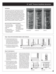
SPEAKER SYSTEMS
S112IV/S115IV
SM10IV/SM12IV/SM15IV
S112IV-OAK
S115IVA-OAK
SM10IV-OAK/SM15IV-OAK
SUBWOOFER
SW118IV
CROSSOVER NETWORK
PN90
Owner’s Manual
Mode d’emploi
Bedienungsanleitung
Manual de instrucciónes
Thank you for purchasing a YAMAHA product. To obtain
maximum performance from your YAMAHA speaker system
and ensure many years of trouble-free operation, we recommend
that you read this Owner’s Manual thoroughly before use.
Contents
Precautions ...................................................................... 2
Connecting the Speakers ................................................ 4
Specifications ................................................................... 6
P.O. Box 1, Hamamatsu, Japan
Technical Data ............................................................... 25
Precautions
AVOID EXCESSIVE HEAT, HUMIDITY, DUST AND VIBRATION
MAKE SURE THE POWER IS OFF BEFORE MAKING
OR REMOVING CONNECTIONS
When choosing a location for your speakers, avoid the following:
Always turn the power switches of system components
OFF prior to connecting or disconnecting cables. Failure to
do so may result in damage to speakers as well as to con-
• Direct sunlight, high temperatures (such as near heaters), or excessively low temperatures.
nected equipment.
• High humidity.
DISCONNECT CABLES BEFORE MOVING THE SYS-
• Areas subject to excessive dust accumulation and vibration.
TEM
To prevent short circuits or breakage of cables, always dis-
• Non-level or unstable surfaces.
connect cables prior to moving system equipment.
HOW TO POWER UP YOUR SOUND SYSTEM
MATCH CONNECTOR POLARITY
To avoid damage to your speakers and other parts of your
system, when you turn on your system, ALWAYS turn the
When using two or more speaker systems, be sure match
the polarity (+/–) of the speaker system connectors to those
power amp on last! This will avoid loud, damaging pops
that will annoy your audience, and blow your speakers.
When you power down, the amplifier should ALWAYS be
at the amplifier. If the polarities do not match, the sounds
produced by the speakers will interfere with each other,
making it impossible to achieve a well-balanced sound
turned off first to avoid the same problems.
field.
KEEP THIS OWNER’S MANUAL IN A SAFE PLACE
FOR FUTURE REFERENCE
To protect your speakers
When choosing a power amplifier to use with your
Poly Switch
speakers, make sure that its power output matches the
speakers’ power capacity (refer to the Specifications on
page 6). Even if the amplifier’s power output is lower
All full-range loudspeakers are fitted with a self-resetting poly switch that protects the high-frequency driver
from damage caused by excessive power.
than the speakers’ PGM (program) power capacity, the
speakers may be damaged when clipping of a high input
signal occurs.
If a loudspeaker cabinet loses high-frequency output,
immediately remove power from the unit and wait for
two to three minutes. The should allow the poly switch
to reset. Re-apply power and check the performance of
The following may cause damage to speakers:
• Feedback caused when using a microphone.
the high-frequency driver before continuing with the
power reduced to a level that does not cause the poly
switch to interrupt the signal.
• Continuous high sound pressure level produced by
electronic instruments.
• Continuous high-power output distorted signals.
On the SW118IV sub woofer, the Poly Switch protects
the woofer and a similar routine should be followed if
• Popping noises caused by turning on equipment, or
by connecting or disconnecting system components
while the amplifier is turned on.
its output is lost.
−2−
ATM Fly-Ware
This product, when used in combination
with amplification and/or additional
loudspeakers, may be capable of produc-
Model S115IVA-OAK only
These speakers are supplied with ATM Fly-Ware rigging
ing sound levels that could cause permanent hearing loss.
hardware installed. The following notes explain how to
prepare these speakers for suspension.
DO NOT operate at high volume levels
or at a level that is uncomfortable. If you
experience any discomfort or ringing in
IMPORTANT! This material does not explain how to
the ears, or suspect an hearing loss, you
should consult an audiologist.
To properly suspend any speaker, a knowledge of struc-
suspend speakers.
tural engineering and structural rigging is REQUIRED.
Suspending loudspeakers requires special tools and techniques. Do not attempt to suspend any speaker system un-
CAUTION!
less you have received specific training to do so.
The following five models can be mounted on speaker
stands: S112IV, S115IV, SM10IV, SM12IV SM15IV. The
The improper installation of flying speakers can result in
bodily injury or death.
use of Ultimate Support Systems, Inc. Model TS-30 or TS33 speaker stands is recommended.
Always consult a licensed engineer to verify the design of
any suspended system. In addition, please follow these
safety steps:
• Use only ONE speaker per stand.
• The loudspeakers and stands must always rest upon a
• Use only hardware specifically designed for rigging applications.
solid, level surface.
• Improper installation or usage could result in the loud-
• Always use an independent safety suspension system as
a backup.
speaker falling and causing injury.
• The top tube of the TS-30 and TS-33 speaker stands has
• Get professional help.
a diameter of 1-1/2", but is tapered to 1-3/8" at the top to
fit in the mounting holes on the five models named. If
you should remove the top tube from a stand, be sure to
To prepare these speakers for suspension:
insert it with the narrow end up when reassembling.
1. Remove the flathead screws from the top of the speaker.
Note: The 3/8" flathead screws use a 7/32" hex wrench.
Take care not to remove both screws from each corner,
The SW118IV subwoofer has a metal socket to allow
mounting of a satellite speaker. Do not use a pole longer
than 56".
as the internal bracket will fall inside the loudspeaker.
2. Apply a drop of thread locking adhesive to the end of
the threads of the eyebolts.
SPEAKER HANDLES
Note: Please use the supplied eyebolts found in the carrying handle of the speaker. If you use any part other
than that supplied, be sure it is Load Rated and know
The handles on your speakers are for transportation. They
are not designed for suspension or hanging. Only the “A”
versions of these speakers are designed for suspension.
that it will be de-rated if not suspended so that the pull
direction is in-line.
Please consult a qualified engineer for proper hanging
techniques.
3. Install the eyebolts into the holes on top of the speaker
and finger-tighten.
4. Securely tighten the eyebolts. Hand tighten +1/2 turn.
5. Inspect the other six (6) flathead screws, making sure
they are tightened down.
−3−
Connecting the Speakers
CONNECTION EXAMPLE 1
The illustration below shows audio connections for a standard setup using two speaker systems.
DAISY-CHAINED
MIXING
CONSOLE
L
GRAPHIC
EQUALIZER
L
POWER
AMPLIFIER
L
SPEAKER
SYSTEMS
R
R
SPEAKER
SYSTEMS
R
DAISY-CHAINING SPEAKERS
Since the speaker systems in this series are equipped with two input terminals that are internally connected in parallel, it is
possible “daisy-chain” speakers by connecting the output from the power amplifier to one phone jack, and a second speaker
system to the other.
All speaker models in this series have a nominal impedance of 8Ω. Since most power amplifiers are designed to provide stable
performance at a load impedance of 4 or 8Ω, Yamaha recommends that no more than two 8Ω speaker systems be daisy-chained
together. This will allow the amplifier to operate properly and avoid overheating.
PHONE PLUG WIRING
The standard input terminals for this unit are 1/4" phone jacks. Connect the speaker leads as shown in this diagram.
Caution: Use only unshielded speaker cable with stranded conductors to connect speakers to the speaker terminals on a power
amplifier. The use of audio cable not rated as sufficient for the amplifier’s maximum output level can create a potential fire
hazard.
−4−
CONNECTION EXAMPLE 2
This example shows audio connections for a system using SW118IV Subwoofers and a PN90 Crossover Network.
TWO-CHANNEL
POWER AMPLIFIER
SPEAKER
SYSTEM
PN90
L
L
LEFT
MIXING
CONSOLE
L
TWO-CHANNEL
GRAPHIC
EQUALIZER
HIGH
INPUT
SW118IV
RIGHT
L
OUTPUT
R
R
L
L
LEFT
INPUTS
TO POWER
AMP INPUTS
RIGHT
R
R
LEFT
LOW
INPUT
RIGHT
OUTPUT
R
SPEAKER
SYSTEM
R
TWO-CHANNEL
POWER AMPLIFIER
SW118IV
• Do not connect the PN90 between the power amplifiers and the SW118IV subwoofers, as doing so will damage the equipment.
• Although the PN90 has a standard load impedance of 15 kΩ, it can be used with loads between 7.5 and 30 kΩ, allowing use
with most power amplifiers.
• Since the LOW signal polarity is inverted at the crossover point between the LOW and HIGH signals, be sure to reverse the
polarity when connecting the SW118IV input jacks to the power amplifier output jacks.
This polarity correction must not be made by reversing the polarity of the connections between the PN90 and the power
amplifiers, as doing so will damage the equipment. Please reverse the polarity between the power amplifiers and the
SW118IVs only.
• The PN90 uses unbalanced connectors. Use shielded audio cable with high-quality phone plugs to connect the PN90.
The balance between the LOW and HIGH signal levels may be adjusted using the power amplifier volume controls. A good
starting point is generally achieved for typical sound sources by raising the LOW signal level about 8 dB higher than that of the
HIGH signal.
−5−
Specifications
Model
SM10IV /SM10IV-OAK
S112IV/SM12IV/S112IV-OAK
Enclosure
S115IV/SM15IV/S115IVA-OAK/SM15IV-OAK
Bass reflex type
Speaker Unit
LF
10" cone
HF
1" driver
Frequency Response
Power Capacity
12" cone
70 Hz to 20 kHz
60 Hz to 16 kHz
NOISE*
100 W
150 W
250 W
PGM
200 W
300 W
500 W
MAX
400 W
600 W
Nominal Impedance
55 Hz to 16 kHz
1000 W
8Ω
Sensitivity
95 dB SPL (1W, 1m)
Nominal Dispersion
15" cone
2" driver
Horizontal
97 dB SPL (1W, 1m)
99 dB SPL (1W, 1m)
60˚
90˚
Vertical
40˚
Crossover Frequency
1.8 kHz
2 kHz
Input Connectors
1.7 kHz
1/4" phone jack x 2 (parallel input)
Dimensions (W x H x D)
SM10IV: 560 x 339 x 277 mm
S112IV: 400 x 638 x 318 mm
S115IV: 475 x 712 x 362 mm
SM10IV-OAK:
SM12IV: 643 x 402 x 344 mm
SM15IV: 720 x 485 x 345 mm
S112IV-OAK: 400 x 620 x 318 mm
S115IV-OAK: 479 x 695 x 360 mm
SM10IV: 12.2 kg
S112IV: 19.3 kg, SM12IV: 19.5 kg
S115IV: 27.5 kg, SM15IV: 26 kg
SM10IV-OAK: 10.5 kg
S112IV-OAK: 18 kg
S115IV-OAK: 27.5 kg, SM15IV-OAK: 26 kg
526 x 316 x 261 mm
SM15IV-OAK: 695 x 479 x 340 mm
Weight
105˚
75˚
SM10IV, SM10IV-OAK,
S112IV, S112IV-OAK,
SM12IV,
S115IV, S115IVA-OAK
120˚
H
30˚
SM15IV, SM15IV-OAK
H
D
W
D
W
Model
SW118IV
Enclosure
Model
Bass reflex type
Speaker Unit
Crossover Frequency
18" cone
Frequency Response
Power Capacity
30 Hz to 2 kHz
PN90
90 Hz, 12 dB/octave (at 15 kΩ load)
Recommended Load Impedance
15Ω
Insertion loss
3 dB
NOISE*
250 W
Input Connectors
1/4" phone jack x 2
PGM
500 W
Output Connectors
1/4" phone jack x 4
MAX
1000 W
Dimensions (W x H x D)
227 x 38 x 76 mm
Nominal Impedance
8Ω
Sensitivity
Weight
0.6 kg
96 dB SPL (1W, 1m)
Recommended Crossover Frequency
90 Hz, 12 dB/octave
Input Connectors
φ6.2
1/4" phone jack x 2 (parallel input)
Dimensions (W x H x D)
542 x 654 x 791 mm
Weight
PN90
32.4 kg
63.5
H
216
W
SW118IV
H
Unit: mm
*: EIA RS-426
D
Specifications subject to change without notice
W
−6−
D
Technical Data / Données techniques
Technische Daten / Datos técnicos
Frequency Response / Impedance
Réponse en fréquence/impédance
Frequenzgang/Impedanz
Respuesta en frecuencia/Impedancia
• SM10IV/SM10IV-OAK
• S115IV/SM15IV/S115IVA-OAK/SM15IV-OAK
100
100
90
80
16
70
4
20
100
1k
90
80
16
70
60
10k
8
4
20
100
FREQUENCY(Hz)
• SW118IV
100
100
90
80
16
70
RESPONSE(dB)
110
RESPONSE(dB)
110
8
4
20
100
10k
FREQUENCY(Hz)
• S112IV/SM12IV/S112IV-OAK
60
1k
1k
10k
90
80
16
70
60
8
4
20
100
1k
FREQUENCY(Hz)
FREQUENCY(Hz)
−25−
10k
Additions
60
8
RESPONSE(dB)
110
RESPONSE(dB)
110
Horizontal Directivity / Directivité horizontale
Abstrahlung horizontal / Directividad horizontal
• SM10IV/SM10IV-OAK
0°
0°
30
40
0°
0°
40
24
30
10
0
10
0
10
0
0
10
0
10
0
10
21
0°
20
30
40
30
40
30
40
180°
180°
21
0°
20
0°
0°
15
24
50
270°
0°
15
20
12
10
12
0°
0
50
90°
0
50
90°
°
60
10
°
20
0°
60
30
°
40
30
30
0°
0°
33
30
50
270°
• 4kHz
• 8kHz
• 16kHz
30
°
0°
33
• 500Hz
• 1kHz
• 2kHz
• S112IV/SM12IV/S112IV-OAK
0°
0°
20
30
0°
40
50
270°
40
30
20
0°
12
0°
180°
21
0°
0°
15
24
180°
21
0°
20
0°
15
10
0°
0
12
0
50
90°
10
0°
50
90°
°
20
60
24
30
°
60
40
°
50
270°
30
30
0°
0°
33
°
30
• 4kHz
• 8kHz
• 16kHz
30
0°
33
• 500Hz
• 1kHz
• 2kHz
• S115IV/SM15IV/S115IVA-OAK/SM15IV-OAK
0°
0°
20
0°
30
40
0°
30
20
180°
−26−
20
0°
21
0°
180°
21
0°
40
24
0°
15
24
50
270°
0°
15
10
12
0
12
0°
0
50
90°
10
50
90°
°
60
20
°
30
0°
60
40
°
50
270°
30
30
0°
0°
33
30
• 4kHz
• 8kHz
• 16kHz
30
°
0°
33
• 500Hz
• 1kHz
• 2kHz
Vertical Directivity / Directivité verticale
Vertikale Richtcharkteristik / Directividad vertical
• SM10IV/SM10IV-OAK
0°
0°
20
30
40
0°
50
270°
40
12
0°
10
0
10
0
10
0
0
10
0
10
0
10
21
0°
20
30
40
30
40
30
40
180°
180°
21
0°
20
0°
0°
15
24
30
0°
15
10
12
0°
0
50
90°
0
50
90°
°
10
60
20
°
24
30
0°
60
40
°
50
270°
30
30
0°
0°
33
30
• 4kHz
• 8kHz
• 16kHz
30
°
0°
33
• 500Hz
• 1kHz
• 2kHz
• S112IV/SM12IV/S112IV-OAK
0°
0°
40
0°
0°
40
24
30
0°
21
20
180°
180°
21
0°
20
0°
0°
15
24
50
270°
Additions
30
0°
15
20
12
10
12
0°
0
50
90°
0
50
90°
°
60
10
0°
°
20
30
60
30
30
°
40
0°
0°
33
°
30
50
270°
• 4kHz
• 8kHz
• 16kHz
30
0°
33
• 500Hz
• 1kHz
• 2kHz
• S115IV/SM15IV/S115IVA-OAK/SM15IV-OAK
0°
0°
40
12
0°
40
30
20
20
0°
21
0°
0°
15
24
180°
180°
21
0°
50
270°
0°
15
0°
30
0°
20
−27−
12
10
50
90°
0
0°
50
90°
°
0
60
10
°
60
20
°
24
30
30
30
40
0°
33
0°
50
270°
• 4kHz
• 8kHz
• 16kHz
°
30
30
0°
33
• 500Hz
• 1kHz
• 2kHz