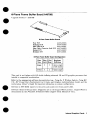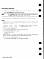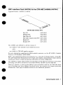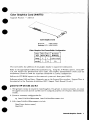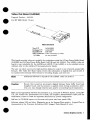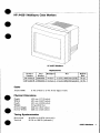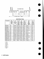
1
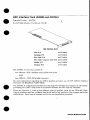
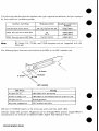
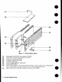
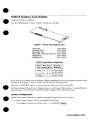
HCRX-8 Graphics Card (A4070A)
●
Upgrade
Product—A4070A
For HP 9000 Models
715/64,
715/80, 715/100, and 725/100
HCRX-8 - 8-Plane Color Graphica Card
New
PJN
Exchange P/N
Flex CableP/N
Flex Cable ConnectorLockP/N
Bucket P/N
Retainer P/N
A4070-66504
A4070-69504
A4071-62001
A4071-40003
A4071-00002
A4071-40001
HCRX-8 Frame-BufferConfiguration
Plane
overlay
Phme Color
8
2
Hardware
8-plane single
This card is an 8-plane with 8/8 double buffering enhanced 2D and 3D graphics processor
installs in HP Model 715/64, 715/80, 715/100, and 725/100 computers.
●
Self-test
in STI ROM reports
that
to the screen and system unit front panel LEDs.
Software release 9.05 and later: Diagnostics are on the SupportWave product. SupportWave
documented
in the Precision ArchitectureRISC: Support Took Manual (9 vols.)
System Configuration
●
Modify the system
1. In root,
create
/etc/mlcnod
software
to support the graphics upgrade connector
output:
a device file for the upgrade by entering:
/devl(new.deuice.
name) c 12 OXOOOOOO
-
Internal Graphics Carda
is
Note
The default address for the built-in graphics (/dev/crt)
715/50, 715/75, and 725/75 is OXOOOOOO.
on HP Models 715/33,
The default address for the built-in graphics (/dev/crt)
on HP Models 715/64,
715/80, 715/100, and 725/100 is OX1OOOOO. Please be aware of this change,
especially with regard to system upgrades.
2. Set read/write
permission
(chmod 666 /dev/(nero_deoice_ nu?ne) -).
3. Include the graphics
following:
upgrade
/dev/(neru-device_
name)
in the screenfile-edit
/usr/lib/Xl
l/XOscreens
to include the
Boot Software Modification
1.After instaHation,
ensure boot software points to the graphics
boot console. In BOOT_ADMIN,type:
preferred
path
console
graphics.
connector
as the
(new-device-slot-nwnber)
For HP Models 715/64, 715/80, and 715/100, this
Note
upgrade
For HP Model 725/100,
new-detizce-slot-nwnber is 1.
this neru.device-.dot-nurnberis 4.
.
2. As root,
reboot
system
using /etc/reboot
-h (do not use HP VUE logout procedure).
grtest
1.The grteet
routine is located in /usr/diag/bin.
For grtest
to execute properly, you must
be logged in as root and set-up files must be configured properly. Device files for grtest
should be set up as follows:
crtr-ru-ru-
cru-ru-rv-
1 root
2 root
(new-device-name )
root
12 OXOOOOOO
Sep 30 09:36
other
12 OX1OOOOO Sep 30 09:37 crt
2. Preserve customer configurationfile:
cp /usr/lib/Xl l/XOscreens
3. Edit /usr/lib/Xll/XOscreens
/usr/liblXl ilXOscreens old
to include:
/dev/(new-device-name)
/dev/crt
Define the screens in this order. This allows grtest routines to test the graphics
properly. This also forces a single X server for both of the graphics devices.
4. Restore
customer’s
mv /usr/lib/Xl
configuration
l/XOscreens.
Internal Graphics Carde
file-execute:
old
/usr/lib/Xl
l/XOscreens
devices
HCRX-24 Graphics
m
Upgrade
I
Card (A4071A)
Product—A4071A
For HP 9000 Models 715/64,
715/80, 715/100 and 725/100
HCRX.24-24-Plane Color Graphica Card
New P/lY
Exrlmnge PIN
A4071-66507
A4071-69507
A4071-62001
Flex CableP/N
Flex Cable CorurectorLockP/N A4071-40003
A4071-00002
Bucket P/N
A4071-40001
Retainer P/N
HCRX-24 Frame-BufferConfiguration
PIsne Plsne Color
Type Depth Maps
24
image
overlay
2
I
1
1
Hmdwsre
BrdTering
8
2
24-plsne single
m
. . 12/12
. . .._ double
8-plane single
This card is a 24-plane enhanced 2D and 3D graphics processor that installs in HP Model 715/64,
715/80, 715/100, and 725/100 computers.
o
m
Self-test
in STI ROM reports
I
I
to the screen and system unit front panel LEDs.
Software release 9.05 and later: Diagnostics areonthe
SupportWave product. SupportWaveis
documented inthe I+ecision -4rrhitecture RISC: Support ?bok Manual (9vols.)
System Configuration
Modify the system
1. Inroot,
software
create adevice
/etc/nrknod
I
to support the graphics upgrade connector
file fortheupgrade
/dev/(new.deuice-nrwne\
output:
by entering:
I
c 12 OXOOOOOO
m
internal Graphics Carda
The default address for the built-in graphics (/dev/crt)
715/50, 715/75, and 725/75 is OXOOOOOO.
Note
on HP Models 715/33,
The default address for the built-in graphics (/dev/crt)
on HP Models 715/64,
715/80, 715/100, and”725/100 is OX1OOOOO.Please be aware of this change,
especially with regard to system upgrades.
2. Set read/write
percnission(chmod
666 /dev/(raew.device-narne)
3. Include thegraphics upgrade inthescreenfiIe-edit
following:
-).
/usr/lib/Xli/xOscreens
toinclude the
/dev/(new_device-name)
Boot Software
Modification
1. After installation,
ensure boot software points to the graphics
boot console. In BOOT-ADMIN,type:
preferred
path
console
graphics-(
For HP Model 725/100,
2. As root,
reboot
system
connector
as the
nero-device_s[ot-nurnber)
For HP Models 715/64, 715/80, and 715/100, this
Note
upgrade
new_devzce-s@nwnber is 1.
neru.deuice_s[ot-number
is 4.
this
using Ietc/reboot
-h (do not use HP VUE logout procedure).
grtest
1.The grtest
routine is located in /usr/diag/bin.
For grtest to execute properly, you must
be logged in as root and set-up files must be configured properly. Device files for grt est
should be set up as follows:
crv-rw-rw-
1 root
root
cru-ru-ru-
2 root
other
2. Preserve
customer
CP /usr/lib/Xl
configuration
llXOscreens
3. Edit \usrllib/Xll/XOscreens
12 OXOOOOOO
Sep 30 09:36
12 OX1OOOOO
Sep 30 09:37
(new-derice-nance )
crt
file:
/usrlliblXi
lfXOscreens.
old
to include:
Idevl(new-deuice-name)
/devlcrt
Define the screens in this order. This allows grtest routines to test the graphics
properly. This also forces a single X server for both of the graphics devices.
4. Restore
customer’s
mv lusrlliblXl
configuration
l/XOscreens.
Internal Graphite Cards
file-execute
old
/usrflib/Xl
llXOscreens
devices
●
8-Plane
●
Upgrade
Frame Buffer Board (A4070B)
Product—A4070B
●
8-PlaneFrameBuffer Board
New P/N
Exc.hsnge P/N
Flex Cable P/N
Flex Cable Connector Lock P/N
Bucket P/N
Retsiner P/N
A4070-66505
A4070-69505
A4071-62001
A4071-40003
A4071-00002
A4071-40001
8-Plane FrameBufferBoard Configuration
Pkme
Type
~ge
Plane Color Hsrdware
DepthMaps Btiering
82
overla~ ii= 8
8-planesingle
or 8/8 double
2
8-plane single
This card is an 8-plane with 8/8 double buffering enhanced
installs in supported workstations.
2D and 3D graphics
processor
that
Refer to the appropriate
software documentation (e.g., Using the X WzndoruSysterrr, Using HPUX, HP Visual User Environment User’s Guide, and Graphics Admmistmtion
Guide) and the
workstation
Owner’s Guide for important information on system configuration.
●
Self-test
in STI ROM reports
to the screen and system unit front panel LEDs.
Software release 9.05 and later: Diagnostics are on the Support Wave product. Support Wave is
documented
in the Precision ,4rchitectemRISC;Support Tads Manual (9 vols.).
Internal Graphica Carda
1
24-Plane
Upgrade
Frame Buffer Board (A4071B)
Prodrrct-A4071B
24-Plane Frame BufferBoard
New F’/iN
Exchange P/N
Flex Cable P/If
Flex Cable Connector Lock P/N
Bucket PfN
Retainer P/N
A4071-66508
A4071-69508
A4071-62001
A4071-40003
A4071-00002
A4071-40001
24-Plane Frame Buffer BoardConfiguration
Plsne Plane color
Type Depth Maps
This card is a 24-plane
workstations.
Hwdware
Btiering
image
24
2
24-planesingle
or 12/12 double
overlay
8
2
E-plane single
enhanced
2D and 3D graphics processor
that
installs
in supported
Refer totheappropriate
software documentation
(e.g., Using the X Window System, Using HPtJX, HP Visual fJser Erwironment
User’s Guide, and Gmphics Administrcation Guide) and the
workstation
Owner’s Guide for important
information on system configuration.
Self-test
in STI ROM reports
to the screen and system unit front panel LEDs.
Software release 9.05 and later: Diagnostics areonthe
SupportWave product.
documented in the Precisiora Architecture
RLSC:Srqport Took Marsual(9vols.).
2
internal Graphica Carcfs
SupportWaveis
HCRX Z-Buffer/Accelerator
Upgrade
m
(HCRX-8Z & HCRX-24Z)
.
O
(A4072A)
Product—A4072A
For HP 9000 Models 715/64,
715/80, 715/100, and 725/100
/’””
,..,”
,..
%-+.
%
. .....
.-.
.,
\
‘ . . . .. .
-.-...+
●
. . . .. .
%..%..%
=-%.7
,,,.’
J’$2
,.,.’
L,’”HCRXZ-Buffer/Accelerator
New
F’/N
A4072-66512
Exchauge P/N A4072-69512
Standofk P/N 0380-4081
This card provides acceleration and Z-buffering for HCRX-8 and HCRX-24 graphics processors.
It mounts on the HCRX-8 or HCRX-24, which install in HP Model 715/64, 715/80, 715/100,
and 725/100 computers.
I
,-,
”
Self-test
in STI ROM reports
to the screen and system unit front panel LEDs.
Software release 9.05 and later: Diagnostics areonthe
SupportWave product. SupportWaveis
documented
inthe Pwcision Architecture RISC:Suppoti
Tools Manual (9vols.)
System Configuration
Modify thesystem
1. In root,
create
/etc/rrJrnod
e
m
adevice
tosupport
thegraphics
file fortheupgrade
/dev/(new.deuice_
upgrade connector
output:
by entering:
rzarne) c 12 OXOOOOOO
-
The default address for the built-in graphics (/dev/crt)
715/50, 715/75, and 725/75 is OXOOOOOO.
Note
—
●
software
on HP Models 715/33,
The default address for the built-in graphics (/dev/crt)
on HP Models 715/64,
715/80, 715/100, and 725/100is OXIOOOOO. Please be aware of this change,
especially with regard to system upgrades.
2. Set read/write
pe~mission(chmod
3. Include thegraphics
following:
ldev/(new.-deuice_
upgrade
666 /dev/(new-derxce-rmrae)m).
inthescreenfde—edit
/usr/lib/Xll/XOscreens
to include the
name)
Internal Graphics Carda
Boot Software Modification
1. After installation,
ensure boot software points to the graphics
preferred boot console. In BOOT. ADMIN,type:
path
console
graphics.
upgrade
connector
as the
e
(new_ detiice_slot_nwnber)
For HP Models 715/64, 715/80, and 715/100, this new_device-slot-rsurnber
Note
For HP Model 725/100,
2. As root,
reboot
system
this rrew_device-sloLmmzber
using /etc/reboot
is 1.
is 4.
-h (do not use HP VUE Iogout procedure).
grtest
1. The grtest
routine
is located in /usrldiag/bin.
For grtest to execute properly,you must
and set-up files must be configured properly. Device files for grtest
should be set up as follows:
be logged in as root
crw-rw-rwcrcr-rv-rw2. Preserve
1 root
2 root
customer
cp /usr/lib/Xl
other
configuration
l/XOscreens
3. Edit /usr/lib/Xll/XOscreens
/dev/(new-device_
/dev/crt
12 OXOOOOOO
Sep 30 09:36
12 OX1OOOOO
Sep 30 09:37
root
(new_ device_ raame )
crt
file:
/usrllib/XlllXOscreens.
old
to include:
name)
Define the screens in this order. This allows grtest routines to test the graphics
properly. This also forces a single X server for both of the graphics devices.
4. Restore
customer’s
UN /usrlliblX
configuration
lllXOscreene.
Internal Graphics Cards
file-execute:
old
/usr/libjXl
llXOscreens
devices
●
It may be to necessary to disable the stereo signal by removing the two-pin berg connector
jumper (see illustration
below) if a non-HP supported
monitor is used. Remove the jumper by
pulling it straight up off the two pins. The jumper
can be placed on one pin for storage (see
illustration
below ).
Removing the Jumper
grtest
for HP-UX 9.05 and 9,X
1. The grtest
routine is located in /usr/diag/bin.
For grtest
to execute properly, you must
be logged in as root and set-up files must be configured properly (see Graphics Administration
Guide).
2. Preserve
customer
cp lusr/lib/X
configuration
ll/XOscreens
3. Edit /usrllib/Xll/XOscreens
/dev/(new-device.
/dev/crt
file:
/usr/lib/X
ll/XOscreens
,old
to include:
name)
Define the screens in this order. This allows grtest
routines to test the graphics
properly. This also forces a single X server for both of the graphics devices.
4. Restore
customer’s
csv /usr/lib/Xl
configuration
l/XOscreens
devices
file-execute:
old
/usr/lib/Xl
l/XOscreens
grtest for HP-UX 10.X
1.The grtest
routine
be logged in as root
Guide).
2. Preserve
customer
cp /usr/lib/Xl
is located in /usr/shin/diag.
For grtest
to execute properly, you must
and set-up files must be configured properly (see Graphics Administration
configuration
l/XOscreens
3. Edit /usr/lib/Xll/XOscreens
/dev/(new.deuice_
/dev/crt
file:
/usr/lib/Xl
l/XOscreens.
old
to include:
name)
Define the screens in this order. This allows grtest
routines to test the graphics
properly. This also forces a single X server for both of the graphics devices.
devices
Internal Graphica Carda
3
4. Restore
customer’s
nw /usr/lib/Xl
4
configuration
l/XOscreens.
Internal Graphics Cards
file-execute:
old
/usr/lib/Xl
~/XOscreens
GSC Interface
●
Upgrade
Card (A4069A and A407~A)
Prod.ct—A4073A
For HP 9000 Models
715/100
and 725/100
GSCInterface Card
New PJN
A4073-66001
Exelcange P/N
A4073-69001
Flex Cable P/N
A4071-62001
FlexCable Connector Lork P/N A4071-40003
The A4069A
is a kit that
one A4073A—GS
Bucket P/N
A4071-00002
Retainer P/l!
A4071-40001
consists of:
C interface
card in EISA form factor
AND
one A2091A—CRX-48Z
graphks
processor
For more information
regarding the A2091A graphics processor,
Processor CE Handbook (A2091-90039).
●
see the HP A2091A
Graphics
The A4073A is a stand-alone interface card that plugs into the GSC bus connector in the system
processing unit (SPU) and serves as the interface between the SPU and the CRX-48Z.
There are, however, a total of three different types of interface cards for the CRX-48Z. Each
type of interface card has a dMerent form factor and/or bus connector that support particular
workstations.
Each type of interface card has its own installation procedure.
.
Internal Graptrica Carda
The following table describes the interface
for their respective installation
guides:
card types, supported workstations,
Interface Card Type
Workstation Model.
I
Full Size SGC Form Factor
and part numbers
Installation Guide Part
Number
730, 735, 735/125, 750,755
A2091-90601
EISA Form Factor for SGC Bus
715
725/75
A2675-90602
A2685-9061O
EISA Form Factor for GSC Bus
715/100, 725/100
A4069-9OO1O
HP Model
CRX-48Z.
and 715/80 computers
Note
712, 715/64,
The following figure illustrates
the location
are not supported
of the LEDs on the GSC interface
with
the
card.
O Green
\
LED Location
Meaning
LED Status
No lights are on.
CRX-48Z is off or disconnected.
Number 2 (Red) is on.
CRX-48Z is on and connected, but no cycles to it yet.
All lights are on.
I Anv
Self-test
other combination.
in STI ROM reports
Normal operation.
I GSC interface card failure.
I
to the screen and system unit front panel LEDs.
Software release 9.o5 and later: Diagnostics are on the SupportWave product. SupportWave
documented in the Precision Architecture RISC: .%pport Tools Manual (9 vols.).
is
●
Internal Graphics Cards
System Configuration
Modify the system
1. In root,
software
to support the graphics upgrade connector
output:
create a device file for the npgrade by entering:
/etc/ncknod
/dev/(raew-deuice_
name) c 12 OXOOOOOO
-
The default address for the built-in graphics (/dev/crt)
715/50, 715/75, and 725/75 is OXOOOOOO.
Note
on HP Models 715/33,
The default address for the built-in graphics (/dev/crt)
on HP Models 715/100
and 725/100 is OX1OOOOO,
Please be aware of this change, especially with regard
to system upgrades.
2. Set readlwrite
3. Include
permission
the graphics
(chrnod 666 /dev/(new-deuice-name)
upgrade in the screenfile-edit
-).
/usr/lib/Xll/XOscreens
to include:
/dev/(new-deuice-name)
Boot Software Modification
1.After installation,
preferred
path
ensure boot software points to the graphics
boot console. In BOOT_AIIMIN,type:
console
Note
2. As root,
graphics-(
upgrade
connector
new_cleuice-$lot_ number)
For the HP Model 715/100 computer,
this raew-deoice_slot_ number is I.
For the HP Model 725/100 computer,
this new-device_ s/et-number
reboot
system
as the
is 4.
-h (do not use HP VUE logout procedure).
using /etc/reboot
grtest
1. The grtest
routine is located in /usr/diag/bin.
For grtest
to execute properly, you must
be logged in as root and set-up files must be configured properly. Device tiles for grtest
should be set up as follows:
crw-rw-rwcrw-rw-rw2. Preserve
1 root
2 root
customer
CP /uSr/lib/Xl
3. Edit /usr/lib/Xl
/dev/(new-device_
/dev/crt
configuration
l/XOscreens
l/XOscreene
root
other
12 OXOOOOOO
Sep 30 09:36
12 Ox10000O Sep 30 09:37
(new. device-name)
crt
tile:
/usr/lib/Xl
l/XOscreens.
old
to inclnde:
name)
Define the screens in this order. This allows grt est routines to test the graphics
properly. This also forces a single X server for both of the graphics devices.
devices
Internal Grephics Carde
4. Restore
customer’s
mv /usr/lib/Xl
configuration
l/XOscreens.
Internal Graphics Carda
file-execute:
old
/usr/lib/Xl
l/XOscreens
●
GSC Interface
Upgrade
Card (A4073A) for the CRX48Z
Product—.44O73.A
(A4069A/A4074A)
or A4074A
CRX-40ZGSC Interface Card
New P/N
A4073-66001
Exchange P/N
A4073-69001
Flex Cable P/N
A4071-62001
Flex Cable Corrector Lock P/N
A4071-40003
Bucket ‘PIN
A4071-00002
Retairrsr PIN
A4071-40001
The A4069A and A4074A is a kit that consists of
one A4073A-GSC
interface
card in EISA form factor
AND
one A2091A-CRX-48Z
graphics processor
Formore information regarding the.42091A
Processor CE Handbook (A2091-90039).
graphics processor,
see the HP A2091A
Graphics
Refer totheappropriate
software dommentation (e.g., ?Jsingthe X Window System, fJsing HPUX, HP Visual User EnrJironment User’s Guide, and Graphics Admiraistmtion Guide) and the
workstation
Owner’s Guide for important information on system configuration.
●
—
The A4073A is a stand-alone interface card that plugs into the GSC bus connector in the system
processing unit (SPU) and serves as the interface between the SPU and the CRX-48Z.
There are, however, a total of three different types of interface cards for the CRX-48Z. Each
type of interface card has a different form factor and/or bus connector that support particular
workstations.
Each type of interface card has its own installation procedure.
Internal Graphics Cards
1
The following table describes the interface
for their respective installation
guides:
card types, supported workstations,
Workstation Model
Installation Guide Psrt
Number
730,735, 735/125, 730.755
A2091-90601
Interface Card Type
Full Size SGC Form Factor
IEISA Form Factor for SGC BUS
715
725/75
I
The HP Model 712 computer
The following figure illustrates
I
715/80, 715/100,
725/100, J Series
EISA Form Factor for GSC Bus
Note
and part numbers
the location
A2675-90602
A2685-90610
o
●
I
●
A4070-90011
is not supported with the CRX-48Z.
of the LEDs on the GSC interface
card.
LED Location
Meaning
LED Status
Self-test
No lights are on.
CRX-48Zis offor disconnected.
Number 2 (Red) is on.
CRX-48Zis on and connected,but no cyclesto it yet.
All lights are on.
Normal operation.
Anv other combination.
GSC interface card failure.
in STI ROM reports
to the screen and system unit front panel LEDs.
Software release 9.05 and later: Diagnostics are on the Support Wave product. SupportWave
documented in the Precision Architecture
RISC: Support Tools Manual (9 VOIS.).
2
Internal Graphics Cards
is
●
grtest for HP-UX 9.05 and 9,X
routine is located in /usr/diag/bin.
For grtest
to execute properly, you must
1. The grtest
be logged in as root and set-up files must be configured properly (see Graphics Administration
Guide).
2. Preserve
customer
cp /usr/lib/X
configuration
ll/XOscreens
3. Edit /usr/lib/Xll/XOscreens
file:
/usr/lib/Xl
l/XOscreens
old
to include:
/dev/(new-device-name)
/devf crt
Define the screens in this order. Thk allows grtest
routines to test the graphics
properly. This also forces a single X server for both of the graphics devices.
4. Restore
customer’s
rnv /usr/lib/Xl
configuration
l/XOscreens.
devices
file-execute:
old
/usr/lib/Xl
l/XOscreens
grtest for HP-UX 10.X
1. The grtest
routine
be logged in as root
Guide).
2. Preserve
customer
CP /usrlliblXl
is located in /usr/shin/diag.
For grtest
to execute properly, you must
and set-up files must be configured properly (see Graphics Administration
configuration
llXOscreens
3. Edit /usr/llb/Xll/XOscxeens
tile:
/usr/lib/Xli/XOscreens.
old
to include:
/dev/(neur.device-rmme)
/dev/crt
Define the screens in this order. This allows grt est routines to test the graphics
properly. This also forces a single X server for both of the graphics devices.
4. Restore
customer’s
rsv /usr/lib/Xl
configuration
l/XOscreens.
devices
tile-execute:
old
/usrllib/Xl
l/XOscreens
Internal Graphics Cards
3
Graphics
color
●
Upgrade
Product
Card (A4077A)
.
— A4077A
For HP 9000 Model 725/100
ColorGraphics Card
New P/N
A4081-66009
Exchange P/N A4081-69009
Color GraphicsCard Frame.Buffer Configuration
image
8
overlay
o
1
8-plane single
iN’A
NA
This card allows the addition of a second graphics monitor to the HP Model 725/100 workstation.
Self-test
in STI ROM reports
to the screen and Series 700 front panel LEDs.
Software release 9.05 and later: Diagnostics are on the Support Wave product. Support Wave is
documented
in the Precision Architecture RISC: SrIpport Tools Manual (9 vols.).
System Configuration
.Modify thesystem
1. In root,
create
/etc/mknod
●
●
Note
2. Set read/write
software
adevice
tosupport
the Color Graphics
file fortheupgrade
/dav/(new.deuice_
Card connector
output:
by entering:
name) c 12 OXOOOOOO
Q
Thedefault
address forthebuilt-in
graphics (/dev/crt)on
HP Mode1725/75
is OXOOOOOO.The default address for the built-in graphics (/dev/crt)
on HP
Model 725/100is
OX1OOOOO.Please he aware of this change, especially with
regard to system, upgrades.
permission
(clmod 666 /dev/(rzew-deoice-nacne)
=).
Internal Graphics Cards
Color Graphics Card (A4077A)
Upgrade
Product
— A4077A
,,/\
ColorGraphicsCard
New PIN
A4081-66009
Exchsnge P/N A4081-69009
Color GraphicsCard Frame.Buffer Configuration
overlay
This card allows theaddition
KA
o
ofonegraphics
NA
display to supported
workstations.
Refer totheappropriate
software documentation (e.g., Using the X Window System, Using HPUX, HP Visual User Environment
User’s Guide, and Graphics Adrninistmtion
Guide) and the
workstation
Owner’s Guide for important information on system configuration.
Self-test
in STI ROM reports
tothescreen
andsystem
unit front panel LEDs.
Software release 9.05 and later: Diagnostics areonthe
documented inthe Precision Arehitectw-eRISC;Support
SupportWave product.
Z’ooLvManttal(9vols.).
SupportWaveis
grtest for HP-UX 9.05 and 9.X
1. The grtest
routine is located in /usr/diag/bin.
For grtest
to execute properly, you must
be logged in as root and set-up tiles must be configured properly (see Graphics Administration
Guide).
2. Preserve
Cp
customer
/usr/llb/Xl
3. Edit /usr/lib/Xl
/dev/(new-device.
fdevfcxt
configuration
l/XOscreens
l/XOscreens
file:
/usr/lib/Xl
l/XOscreans. old
to include:
name)
Internal Graphics Cards
1
●
Define the screens in this order. This allows grtest routines to test the graphics
properly. This also forces a single X server for both of the graphics devices.
4 Restore
customer’s
mv /usr/lib/Xl
configuration
l/XOscreens
devices
file-execute:
old
/usr/lib/Xl
●
l/XOscreens
for HP-UX IO,X
grtest
1. The grtest
routine is located in /usr/shin/diag.
For grtest
to execute properly, you must
be logged in as root and set-up files must be configured properly (see Graphics .4dnrinistration
Guide).
2. Preserve
customer
cp /usr/lib/Xl
configuration
l/XOscreens
3. Edit /usr/lib/Xll/XOscreens
/dev/(new-decice_
/dev/crt
/usr/lib/Xll/XOscreens
old
to include:
name)
Define the screens in this order. This allows grtest routines to test the graphics
properly. This also forces a single X server for both of the graphics devices.
4. Restore
m
customer’s
/usr/lib/Xl
●
file:
configuration
l/XOscreens.
devices
tile-execute:
old
/usr/lib/Xli/XOs
creens
●
●
2
Internal Graphics Cards
●
●
Dual Color Graphics
●
Upgrade
Product
Card (A4078A)
— A4078A
●
Figure 9.1. Dual Color Graphics Card
New P/N
A4081-66005
Exchange P/N A4081-69005
The Dual Color Graphics
the following frame-buffer
Card contains two graphics processors.
configuration:
Each graphics
processor
has
Dual Color Graphics Card Frsme-BufferConfiguration(Per Processor)
This card allows the addition
Note
o
Self-test
of two graphics monitors to supported
Refer to the appropriate
System,
Using HP-UX,
Graphics
Administration
import ant information on
in STI ROM reports
workstations
software documentation
(e.g., Using the X Window
HP Visual Use~ Environment
User’s Guide, and
Guide) and the workstation
Owner’s Guide for
system configuration.
to the screen and the system unit front panel LEDs.
Software release 9.05 and later: Diagnostics are on the SupportWave product. SupportWave
documented in the Precision Architecture RISC: Support Tools Manual (9 vols.).
Irrternsl Graphica Csrds
is
1
grtest
for HP-UX 9.05 and 9.X
routine is located
1. The grtest
be logged in as root.
2. Preserve
customer
in /usr/diag/bin.
configuration
cp /etc/Xll/XOscreens
3. Edit /etc/Xil/XOscreens
For grtest
to execute properly, you must
●
file:
/etc/Xll/XOscreens
.old
to include:
/dev/(device-namel)
/dev/(derrice-narnc2)
Define the screens in this order. This allows grtest routines to test the graphics
properly. This also forces a single X server for both of the graphics devices.
4. Restore
customer’s
configuration
nw /etc/Xll/XOscreens
grtest
for HP-UX
customer
file-execute:
old
/etc/Xll/XOscreens
10.X
1. The grtest
routine is located
be logged in as root.
2. Preserve
devices
in /usr/shin/diag.
configuration
cp /etc/Xll/XOscreens
3. Edit /etc/Xll/XOscreens
For grtest
to execute properly, you must
file:
/etc/Xll/XOscreens
.old
.
to include:
/dev/(deuice-namel)
/dev/(deuice_name2)
Define the screens in this order. This allows grtest routines to test the graphics
properly. This also forces a single X server for both of the graphics devices.
4. Restore
customer’s
configuration
cur /etc/Xll/XOscreens
2
Internal Graphics Cards
old
file-execute:
/etc/Xll/XOscreens
devices
●
Z-Buffer
(A4242A) for 8-Plane and 24-Plane Frame
and Accelerator
Buffer Boards
Upgrade
Product—A4242A
,
‘.
,
/ /
/
/“
.
...
“q-;...
o
.
* a-”?
a
-----
-.
‘..
--- ,*><‘“>-J
-.*.
-.
.:,,
+?
/
~ ;+
Z-Buffer and Accelerator for E.Plane and 24-Plane Frame Buffer Boarda
New PJN
A4242-66001
ExchsngeP/N A4242-69001
StsndolTsP/N 0380-4081
This card provides acceleration and Z-buffering for the 8-Plane Frame Buffer Board (A4070A/B)
and 24-Plane Frame Buffer Board (A4071A/B). It mounts on the 8-Plane Frame Buffer Board
or 24-Plane Frame Buffer Board, which is then installed into supported workstations.
Ensure that connectors are properly aligned between the frame buffer board and
accelerator,
and that pressure is applied evenly during installation;
otherwise,
you may damage connector pins and/or surrounding board components.
Caution
Refer to the appropriate
software documentation (e.g., Using the X Window System, Using HPfJX, HP Visual User .Erzuirorsment User’s Guide, and Graphics Adrrsinistrafion Guide) and the
workstation
Owner-’s Guide for important information on system configuration,
Self-test
in STI ROM reports
to the screen and system unit front panel LEDs.
Software release 9.05 and later: Diagnostics are on the SupportWave product. SupportWave
documented in the Precision Archttectrme RISC: Support TOOk Manual (9 vols.).
m
●
is
grtest for HP-UX 9.05 and 9.X
1.The grtest
routine is located in /usr/diag/bin.
For grtest
to execute properly, you must
be logged in as root and set-up files must be configured properly (see Graphtcs Administration
Guide).
2. Preserve
customer
configuration
cp /usr/lib/Xl
3. Edit /usr/lib/Xl
llXOscreens
l/XOscreens
/dev/(new_deuice_
Icievfcrt
file:
/usr/lib/Xl
l/XOscreens
old
to include:
name)
Internal Graphics Carda
1
Define the screens in this order. This allows grtest routines to test the graphics
properly. This also forces a single X server for both of the graphics devices.
4. Restore
customer’s
mv /rrsr/lib/X
configuration
file-execute:
ll/XOscreens
old
lusrlliblXl
devices
llXOscreens
grtest for HP-UX 10.X
1 The grtest
routine is located in /usr/shin/diag.
For grtest
to execute properly, you must
be logged in as root and set-up tiles must be configured properly (see Graphics Administration
Guide).
2 Preserve
customer
Cp /usr/lib/Xl
configuration
l/XOscreens
3 Edit /usr/lib/Xll/XOscreens
/dev/(new-deuice_
/dev/crt
file:
/usrllib/Xl
l/XOscreens
old
to include:
name)
Define the screens in this order. This allows grtest routines to test the graphics
properly. This also forces a single X server for both of the graphics devices.
4 Restore
customer’s
rsv /usr/lib/Xl
2
configuration
l/XOscreens.
Internal Graphics Cards
file-execute:
old
/usrllib/Xll/XOscreens
devices
a
A4244L! Graphics
Option
A4244A Graphica Option
‘Retaining Clip for Front Plane 3-Wide N/A
Retaining Clip for Front Plane 2-Wide N/A
~
●
m
A4244-00011
End Retaining Clip, 2 per board
N/A
A4244-62001
Spacer and Screw Assembly (2-Wide)
NJA
A4244-62002
Spacer and Screw Assembly (3-Wide)
N/A
0380-4378
Standoffs
N/A
The A4244A Graphics Option is a 3D graphics subsystem consisting of a geometry accelerator
and frame buffer board.
There are also two optional products associated with the A4244A
Graphics Option: a video out board and a texture mapping board.
Note
The A4248A video out product requires additional
software.
Refer to the appropriate
software documentation (e.g., Using the X Window System, Using HPUX, HP Visual User Environ~ent
User’s Guide, and Graphics Administration
Guide) and the
workstation
Owner’s Guide for important information on system configuration.
Self-test
in STI ROM reports
to the screen and system unit front panel LEDs.
Software release 9.0.5 and later: Diagnostics are on the Support Wave product. Support Wave is
documented in the Precision Architecture RISC: Support Took Manual (9 vols.).
m
Internal Graptrica Cards
1
@
Figure 1-1. A4244A GraphicsOption
Retaining Clip (2-Wide (not shown) or 3-Wide)
Front Plane (2-Wide (not shown) or 3-Wide)
Geometry Accelerator Board
Video Out Board (Optional)
Standoffs (Optional)
Texture Mapping Board (Optional)
Frame Buffer Board
Board Placeholder
(used with Front Plane 3-Wide to take the place of a missing board
(e.g., when you have a video out board, but no texture mapping board))
Spacer and Screw Assembly (2-Wide (not shown) and 3-Wide)
2
Internal Graphics Carda
Upgrade Instructions
1. Remove the A4244A Graphics Option board set from the workstation’s
card cage.
2. Flip the board set over so it is laying on the Front Plane (@) and the Spacer Assembly
is on top.
(@)
3. Loosen the screw in the Spacer Assembly and lift the Spacer Assembly off of the board set.
4. Flip the board set over agairrso the Front Plane (@) ison top (hang metal tongues of the
board set over the edge of a table to get the board set to lay more horizontally).
5. Remove the Retaining Clip (Q) by using your thumb to pry each side of the clip off of the
Front Plane, Remove the End Retainers (not shown in Flgurel-l)
from the Front Plane in
the same manner, if applicable,
6. Carefull
yflipth
eboardse
toveragainsothat
the board setisresting
on the Front Plane.
7. P u1l the desired board(s) off the Front Plane by holding down the Front Plane while carefully
working the board(s) out of the Front Plane connectors.
Note
If you are upgrading from a two board set, you will need to remove both boards
andswitch toa3-Wide Front Plane. The Front Plane canonly be positioned one
way. Improper positioning of the Front Plane can result in damage to connector
pins. Ensure that the Front Plane is in the correct position by aligning the
locators on the Front Plane and the boards (ensure that the Xs on the Front
Plane match the Xs on the graphics boards, likewise with the 0s).
aVideo Out Board ((7J), mount the Video Out Board onto the Frame
8. If you preinstalling
Buffer Board (@)using
the Standoffs(@). Then place thecombined
boards into the Front
Plane, using Figure l-las preference. Ifyouare notinstaRing
aTexture Mapping Board at
this time, you must insert the Board Placeholder (@) in the 3-Wide Spacer Assembly ((3J)
as shown in Figure 1-1 totakethe
place of the Texture Mapping Board.
9. If you are instalhng aTexture Mapping Board, instaU the board into the Front Plane by
sliding the Texture Mapping Board (@) down in between the Geometry Accelerator and
Frame Buffer Boards until the board’s connectors are firmly seated in the Front Plane
connectors.
10. After upgrade boards preinstalled
into the Front Plane connectors, carefully flip the board
set over so that the Front Plane ison top and replace the Retaining Clip.
11. Flip the board set over again so that it is resting on the Front Plane and replace the Spacer
Assembly.
screw.
After replacing
the Spacer Assembly, ensure thatyou
tighten the Spacer Assembly
12. Flip the board set over once again and install the set into the workstation
(lurrer’s Guide for supported slots).
Note
(see the workstation
If a customer
has purchased the A4248A video out product or A4245A
texture mapping product for the A4244A frame buffer set, a designated HP
representative
rrrrtst install this upgrade.
Internal Graphics Cards
3
grtest for HP-UX 9.05 and 9.X
routine is located in /usr/diag/bier.
For grtest
to execute properly, you must
1. The grtest
be logged in as root and set-up files must be configured properly (see Graphics Administration
Guide).
2. Preserve
customer
cp /usr/lib/Xl
configuration
l/XOscreens
3. Edit /usr/lib/Xll/XOscreens
/dev/(new_device_
file:
/usr/lib/Xl
l/XOscreens.
old
to include:
rmrre)
/dev/crt
Define the screens in this order. This allows grtest routines to test the graphics
properly. This also forces a single X server for both of the graphics devices.
4. Restore
customer’s
mv lusr/liblXl
configuration
l/XOscreens.
devices
file-execute:
old
lusr/liblXl
llXOscreens
grtest for HP-UX 10.X
1. The grtest
routine
be logged in as root
Guide).
2. Preserve
customer
cp /usr/lib/Xl
is located in /usr/shin/diag.
For grtest to execute properly, you must
and set-up files must be configured properly (see Grophics Administration
configuration
l/XOscreens
3. Edit /usr/lib/Xll/XOscreens
/dev/(new_device_
/dev/crt
file:
/usr/lib/Xl
l/XOscreens.
old
to include:
name)
Define the screens in this order. This allows grtest routines to test the graphics
properly. This also forces a single X server for both of the graphics devices.
4. Restore
customer’s
cm /usr/lib/Xl
4
configuration
l/XOscreens.
Internal Graphics Cards
file-execute:
old
/usr/lib/Xl
l/XOscreens
devices
m
Video Out Board (A4248A)
Upgrade
Product—A4248A
For HP 9000 Model J Series
Video Out Board
New F’/N
Exchange P/N
Stsndofis P/N
Video Connectors
& Cables
A4248-66001
A4248-69001
0380-4378
Video connectors & cables
are not provided,
This board provides video out capability for workstations using the 8-Plane Frame Buffer Board
(A4070B) and 24-Plane Frame Buffer Board (A4071B) and the A4244A. The A4248A video out
board is user-installable
for the A4070B and A4071B. If the A4248A is to be installed into an
A4244A, refer to the A4244A CE documentation for details.
The user can select an area of a high resolution display for output to one of several analog video
formats. The Video Out Board option receives ttds information in digital form and encodes it
to standard international
video formats for recording, display, and other use.
Note
Additional
software is required for the A4248A video out product.
Caution
Ensure that connectors are properly aligned between frame buffer board and
daughter board, and that pressure is applied evenly during installation; otherwise, you may damage connector pins and/or surrounding board components.
m
●
a
Refer to the appropriate software documentation (e.g., Using the X Window System, Using HPUX, HP Visual User Environment User% Guide, and G~aphics Administmtion
Guide) and the
workstation
Owner’s Guide for important information on system configuration.
Self-test
in STI ROM reports
to the screen and systdm unit front panel LEDs.
Software release 9.05 and later: Diagnostics are on the Support Wave product. Support Wave is
documented in the Precision Architecture RISC: Support Toots MrsnurIl (9 vols.).
Internal Graphite Cards
1
e
grtest for HP-UX 9.05 and 9.X
1.The grtest
routine is located in /usr/diag/bin.
For grtest
to execute properly, you must
be logged in as root and set-up files must be configured properly (see Graphics Administration
Guide).
2. Preserve
customer
cp /usr/lib/Xl
configuration
l/XOscreens
3. Edit /usr/lib/Xll/XOscreens
/dev/(new-deuice_
/dev/crt
file:
/usr/lib/Xl
l/XOscreens.
old
to include:
●
name)
Define the screens in this order. This allows grtest routines to test the graphics
properly. This also forces a single X server for both of the graphics devices.
4. Restore
customer’s
mv /usr/lib/Xl
configuration
lfXOscreens.
devices
file-execute:
old
/usr/liblXl
llXOscreens
grtest for HP-UX 10.X
1. The grtest
routine is located in /usr/shin/diag.
For grtest to execute properly, you must
be logged in as root and set-up files must be configured properly (see Graphics Administration
Guide).
2. Preserve
customer
configuration
cp /usr/lib/Xll/XOscreens
3. Edit /usr/lib/Xll/XOscreens
file:
/usr/lib/Xll/XOscreens
old
to include:
/dev/(new-dev~ce_ name)
Idevlcrt
Define the screens in this order. This allows grtest routines to test the graphics
properly. This also forces a single X server for both of the graphics devices.
4. Restore
customer’s
mv /usr/lib/Xl
2
configuration
l/XOscreens.
Internal Graphica Carda
fil~execute:
old
/rcsr/lib/Xl
●
l/XOscreens
devices
HP A4251 Multisync Color Monitors
/
/
HPA4251 ‘Monitors
Replacements
Product
Part
Number
Number
HP A4251A
2090-0337
HP A4251B
2090-0334
Size
Refresh
Rate
Northern
17 inch (128OX1O24pixels)
60 HZ
Southern
17 inch (1280xI024 pixels)
60
Hemisphere
HZ
Cable
A4251-62001
9-Pin D-Sub to 15-Pin D-Sub Signal Cable
Physical Dimensions
Height
Width
Depth
Weight
Screen Height
Screen Width
435 mm (17.12 inches)
421 mm (16.57 inches)
431 mm (16.96 inches)
21 kg (46.3 lb,.)
240 mm (9.45 inches)
320 mm (12.6 inches)
Timing Synchronization
Horizontal
Vertical
30 KHz to 64 KHz (automatic)
50 Hz to 100 Hz (automatic)
A4251
Monltora 1
Controls and Locations
u___
?
15
v
Front ControlPanel
Basic Controls and LED indicator Functions
I Power Switch
2 Power Indicator (Dual Color)— No adjustments made: I,ED glows greeu.
Adjustment
function selected: LED glows orange.
3 Power Saver Indicator
4 Contrast
s Brightness
(Single Color) —Glows green in suspend or off modes.
Control
Control
6 Variable Adjustment
Control—Use the Variable Adjustment Control to adjust the displayed
image when a control function is implemented (indicator I,ED is orange). ‘IJmn the Variable
Adjustment, Control counterclockwise
to decrease the value of the adjustment function. Turn
the cent rol clockwise to increase the value of the adjustment function.
Approximately
3 to 4 seconds after completing an adjustment, the indicator LED toggles
between orange and green, then remains orange for 6 to 7 seconds, indicating that the
adjustment
is saved. The On-Screen Display (OSD) remsjns on for about 10 seconds. When
it disappears, the indicator LED turns back to green.
2
A4251 Monitors
Multifunction Buttons
This monitor incorporates both single and multifunction buttons. The multifunction buttons can
access a second function in addition to the first one. ‘1’oaccess the second adjustment function,
push the function button twice. The table below shows yuua list of multifunction buttons.
Button
Push
Pmih
Number
Once
Twice
7
8
9
10
11
12
Note
If you push
H-Position
V-Position
H-Size
V-Size
Side Pincushion
‘ftapezoid
Help
Iielp
Help
Help
Help
Help
a button three times, the selected
fnrrction
returns
to normaI
condition.
7 Horizontal Position/Help—Push
this button once to adjust the horizontal
pobition
(centering) of the display, Use the Variable Adjustment Control to adjust. Push this button
twice for help.
8 Vertical Position/Help
-Push this button once to adjnst the vertical position (centering)
of the display. Use the Variable Adjustment Controi to adjust. Push this button twice for
help.
9 Horizontal
Size/Help—Push
this button once to adjust the horizontal size (width) of the
display. Use the Variable Adjustment Control to adjust. Push this button twice for help,
10 Vertical Size/Help—Push
this button once to adjust the vertical size (height) of the
display. Use the Variable Adjustment Control to adjust. Push this button twice for help.
Note
Do not push this button longer than 7 seconds continuously.
operation resets all of the data in the user memory area.
If you do, thk
11 Side Pincushion/Help—Push
this button once to adjust the vertical sides of the dkplay
from bowing in (pincushion) or bowing out (barrel distortion), ‘lhrn the Variable Adjustment
Control until the vertical sides are straight. Push this button twice for help.
12 ‘lYapezoid/Help-Push
this button once to access the Trapezoid adjustment
control to
correct any Trapezoid (keystone-like) distortion of the display. Push this button twice for
help.
13 Recall—Use
this button to recall factory preset settings,
When the Recall button is
pushed, the indicator LED will change color from green to orange and the OSD will appear.
Keep pressing tl~e recall button for 2 to 3 seconds nntiI the indicktor LED’s color changes to
green, which indicates that the factory settings for that timing ‘have been recalled.
Note
This operation
signal timing.
resets all of the data in the user memory
area for the current
A4251 Monitors
3
14 Degauss -Magnetic fields can hnihl up on the CRT and cause color impurity.
tJse the
degauss switch to demagnetize
the CRT, Push the switch once to activate the degaussing
circuit. ‘1’}~edcgaussing circuit automatically turns itself off after a few seconds.
15 Parallelogram—1’ush
the Horizontal Position button and the Vertical P&ition button
simultaneously
for 4 to 5 seconds to activate the parallelogram function.
Use the Variable
Adjustment
Control to adjust.
On-Screen Display
This monitor features an On-Screen Display (OSD) that shows information about the display
settiugs to the user, The OSD appears on the screen when a function button is selected. ‘I’he
OSD shows the name, range, and current setting of the control function.
In addition, the 0S1) shows the current input sigrwd frequency and the list of factory and user
preset timings. The OSD remains activated approximately 10 seconds after any adjustment is
completed.
Help Function
When you activatethe
Help fllnction, the OSDsl~ows thecontents of the factory preset timing
modes and user modes. User modes are followed by horizontal and vertical sync polarity
(P: Positive, N: Negative). Usethe Variable Adjustlnent Control to(`page'' through the list.
Custom Display Settings
This monitor has factory-preset
display settings for each of the, timings listed in the ,“Timing
Specifications”
section of this handbook.
As a result, the monitor automatically
adjusts to an
optimum size and position when it senses one of the standard signal timings.
In addition to preset
The microprocessor
specific signal timing
making adjustments
720 X 40070 HZ.
Note
timings, the monitor has memory for up to 11 user-defined timings jsettings.
automatically
memorizes the display settings that the user prefers for a
and automatically
adjusts when the monitor senses that signal (this inclndes
10 factory-preset
timings). An example of a user-defined setting would be
CRX and HCRX graphics run at a horizontal scan rate of 76.65 KHz, which is
outside the range of this monitor. Therefore, CRX and HCRX graphics are not
compatible with this monitor.
Power Management
PowerSaver
System
runs in four operational
states:
On
Stand-by
Suspend
off
Normal operation.
No video signal.
Minimal power for quick recovery.
Non -operation.
Note
The Power Management System function may not be supported
operating system or X-Window system.
4
A4251
Monitors
with the current
Timing Specifications
One Horfz. Line
l-r
1
w5
4
-- 3-J*
1+ –----1~
A4251 HorizontalTiming
Resolution
Retieeh
Hate
(Hz)
Dot
clock
Iheq.
(MHz)
Horis.
(1)
Sweep
Rate
(KHz)
Horir..
Period
(,1S)
(2)
Hock
Active
Time
(p,)
(3)
Horiz.
Blank
Time
(p.)
(4)
Horiz.
Pront
Porch
(p.)
(5)
44=
Horiz.
Sync
Width
(p.)
(6)
Horiz.
Bark
Porck
(/Is)
11.4688 31.7776 25.4220 6.3555 e
1.8133 (–)
1.9067
11.4750 31,7712 25.4170 6,3542 0.6354
1.8125 (-)
1.9063
17.5000 26.6667 20.3175
640X4802
75
31.5000
).0317 (–)
3.8095
800X6003
60
40.0000 17.8788 26.4000 20.0000 6.4000 1,0000 1.2000 (+)
2.2000
800X6002
72
50.0000 18.076920.800016.00004.8000 1.1200 !.4000 (+)
1.2800
800X6002
75
49.5000 16.875021.333316.16165.1717 0.3232 .6162 (+)
3.2323
65.0000 18.363t 20.6769 15.7538 4.9231 0.3692
2.4615
1024X7683 60
6.34W
0.5079
!.0923 (–)
1024X7682 70
75.0000 16.4759 17,7067 13,6533 4.05J3 0.3200 ..8133 (-)
1.9200
1024X7682 75
78.7500 ;0.0229 16.6603 13.0032 3.6571 0,2032 ..2190 (+)
2.2349
1024X7684 75
84.5870 i2,9368 15.8890 12.1059 3.7831 0.7566 .5132 (–)
1.5132
1152X900
92.94
66
128OX1O24 60
i1.7952 16.1825 12,3951 3.7874 0.3013
!.3772 (–)
2.1089
108.181 i3.3378 15,7884 11.8320 3.9563 0,4067
.7009 (–)
1.8488
1 PC mod.
2 VESA
standard
3 VESA
guidefine
4 HP mode
A4251 Monitors
5
9---4-10
----4-–
–
b
—.
8
—
-7 (to end ot prev. V. blank) ——–—–—- 4
4 —
A4251 VerticalTiming
Resolution
Ro-
640X4001
640X4801
640X4802
(7-8)
Vert.
(8)
Vert.
(lo)
Vert.
Sync
Width
(m)
(Hz)
Period
(MS)
Active
~
Blank
~~
69.9306
14.2999
12.7110 1.5889
0.3813
0.0636 (+)
1.1440
59.9524
16.6799
15.2502 1.4297 0.3177
0,0635 (-)
1.0485
10.0267 10.0800 (-)
10.4267
4=!=
444=
75.000
113.3333112.800010.5333
800X6003
60.3165
800X6002
72.1876 [ 13.8528112.480011.3728
16.5792
15.8400 0.73(12 0.0264
0.1056 (+)
10.6072
10.7696 10.1248 (+)
10.4784
800X6002
75.0000
13.3333
12.8000 0.5333
0.0213
0.0640 (+)
j 0.4480
1024X7683
60.0038
16.6656
15.8799 0.7857
0.0620
0.1241 (-)
0.5996
1024X7682
70.0694
14.2716
13.5987 0.6729
0.0531
0.1062 (-)
0.5135
1024X7652
75.0286
13.3283
12.7951 0.5331
0.0167
0,0500 (+)
0,4665
1024X7684
74.9247113.3467
1152X900
65.9501
I28OX1O24
59.9790116.6725116.1673
1 PC mode
2 VESA
st.ndiwcl
3 WISA
guideline
4 HP rnodc
6
(9)
vat .
Ikont
Porch
(ma)
(11)
Vert.
Back
Porch
(m)
(7)
Vert.
fresh
Rate
A4251 Monitors
15,1630
I 12.202711.1440 10.06355 \ 0.06355 (-)
14.5642 0.5988
00324
10.0647 (-)
10.5052 10.0473610.04736 (–)
11.0169
10.5017
10.41049
Troubleshooting
Chart
Problem
There is no
~ocntim
Itcmto Cbcck
screen image.
Check to see that power cord is plugged
rolls or tears.
in.
Rear
Ensure that signal cable is connected.
Rear
Ensure that signal source is turned
Computer
on.
Ensure that signal cable pin assignment
correct,
I)isplay
Front
Check power switch. LED should be on.
is
Rear/Computer
Rear
Check to see that signal cable pin
assignment is correct.
Scan the frequency of video board.
Display
is too dark or too
Use the contrast and brightness
Computer
to
Front panel
bright.
correct
LED color is orange.
Check signal cables connection.
Rear/Computer
LED is blinking
orange-green.
Check signal presence.
Computer
Power Management
Computer
LED is blinking
orange,
on-off
Colors are not uniform
(there are dark or shadow
areas).
Display
small.
is
too
large
or too
the problem.
conttols
~
System
Push the degauss bulton
the degaussing circuit.
once to activate
Push the horizontal sitic or vertical size
Front panel
Front
button once to adjust the width or the
height of the display. Use the Variable
Adjustment Control to adjust,
A4251 Monitors
7
●
HP A4330 Multimode Color Monitor
1HP A4330 Monitor
k
Replacement
Re&sh
Rate
Part
Hemisphere
Size
Product
Number
Nmnber
HP A4330A 2090-0525 Northern 17 inch (12SOX1O24pixels)
Multimode
HP A4330B
Multimode
2090-0526
Southern
17 inch ( I28OX1O24pixels)
Cable
m
a
D2800-80006
D2817-80006
or
15-Pin D-Sub to 15-Pin D-Sub Signal Cable
Physical Dimensions
Height
Width
Depth
Weight
Screen Height
Screen Width
426 mm (16.8 inches)
434 mm (17.1 inches)
444 mm (17.5 inches)
19 kg (41.8 lbs.)
240 mm (9.45 inches)
320 mm (12.6 inches)
Timing Synchronization
o
Horizontal
Vertical
30 KHz to 85 KHz (automatic)
50 Hz to 150 Hz (automatic)
A4330 Monitor
1
Controls and Locations
1
Q#mxm@@@@@w”
la%d
FEi
Qw.
e
4}VA
1
‘ .L ‘
@
2
@
@
@
@
@
5
@
@)
Front ControlPanel
Basic Controls and LED Indicator Functions
1 Power
Button
2 Power Indicator (Dual Color)—No
Adjustment
function
selected:
adjustments made: LED glows green.
LED glows orange.
3 Contrast Control
4 Brightness
Control
5 Adjustment
Controls—Use
these buttons to adjust the displayed image when a control
function is implemented
(indicator LED is orange). Push the A or } button to increase
the value of the adjustment
function.
Push the ~ or 4 button to decrease the value of the
adjustment function.
After completing an adjustment,
the indicator LED toggles between orange and green, then
remains oramge for about 10 seconds, indicating that the adjustment is saved. The On-Screen
Display (OSD) remains on during this time. When it disappears, the indicator LED turns
back to green.
2
A4330 Monitor
Multifunction
Buttons
Thk monitor incorporates both single and multifunction buttons. The multifunction buttons can
access a second function in addition to the first one. To access the second adjustment function,
push the function button twice. The table below shows you a list of multifimction buttons.
Button
Push
Number
Once
Push Twice
6
Position (H/V)
User, Preset Mode
7
8
9
Size (H/V)
Pincushion/Trapezoid
Color Temp.
Recall
Information
Pamllel/Tilt
Color Control
BNC/D-Sub
10
6 Position (H/V)
vertical position
Push thk button
of the user modes
through the list.
Push Three
Trees
Sync Select
/User or Preset Mod*Push
tMsbutton
once toadjust
(centering) of the display. Use the adjustment control
twice to access the user and preset modes. The OSD
and factory timing modes. Use the adjustment control
thehorizontd
and
buttons to adjust.
shows the contents
buttons to “pagen
7 Sise (H/V) /Information—Push
this button once to adjust the horizontal and vertica.l size
of the display. Use the adjustment control buttons to adjust. Push this button twice to access
the Information function.
The OSD shows the contents of this monitor’s specification.
Use
the adjustment
control buttons to”page’’ through the list.
8 G/D (Geometric
Distortion) /Parallel & Tilt-Push
this button once to adjust the
pincushion andtrapezoid
of the display. Use the adjustment control buttons to adjust. Push
this button twice to adjust the parallel and tilt of the display. Use the adjustment control
buttons to adjust.
9 Color Temperatue/Color
Control/Sync Select-Push
tMsbutton
once tochoose the color
temperature
of the dkplay.
Use the A and Y adjustment control buttons to select one of
either 9300°K color, 6500DK color, or user color. 9300”K and 6500”K are the factory color
modes. User color is adjustable.
The initial value of channel 3is equaf to 9300°K. To change
this color value, select user color, then select thecolor control button for hue and saturation.
Adjust with theadjustment
control buttons. Thenewcolor
value automatically
saves in20r
3 seconds.
Push this button twice to adjust thecolor hue and saturation.
Use the <and } adjustment
buttons to
control buttons to access the color saturation and use the A and ? adjustment
access the hue function.
Push this button three times to select the video signal type. Use the A and v adjustment
control buttons to select your choice. Always use the default setting (Separate) unless your
entire screen appears too green. Ifthk occurs, select Sync-on-Green.
10 Recal-Use
this button to recall factory preset settings.
When the Recall button is
pushed, theindlcator
LED will change color-from green to orange and the OSD will appear.
Keep pressing the recall button for several seconds until the indicator LED’s color changes to
green, which indicates that the factory settings for that timing have been recalled.
Note
This operation
signaJ timing.
resets allofthe
data in the user memory
area for the current
A4330 Monitor 3
Push this button twice quickly to toggle between BNC and D-Sub connectors. This is available
when both computers are connected and running. Otherwise, upon powering on, the monitor
automatically
uses the active input.
11 Degauss—Magnetic
fields can build up on the CRT and cause color impurity. Use the
degauss button to demagnetize
the CRT. Push the switch once to activate the degaussing
circuit. The degaussing circuit automatically
turns itself off after a few seconds.
Note
Do not push the degauss button longer than five seconds.
If you do, this
operation resets all of the data in the user memory area. If this occurs, you
must reset your user adjustments.
On-Screen Display
Th]s monitor features an On-Screen Display (OSD) that shows information about the display
settings to the user. The OSD appears on the screen when a function button is selected. The
OSD shows the name, range, and current setting of the control function.
In addition, the OSD shows the current input signsJ frequency and the list of factory and user
preset timings. The OSD remains activated approximately 10 seconds after any adjustment is
completed.
Information Function
When you activate the Information function, the OSD shows the contents of the factory preset
timing modes and user modes. User modes are followed by horizontal and vertical sync polarity
(P: Positive, N: Negative). Use the adjustment control buttons to ,“page” through the list.
Custom Display Settings
This monitor has factory-preset
display settings for each of the timings listed in the “Timing
Specifications”
section of this handbook.
As a result, the monitor automatically
adjusts to an
optimum size and position when it senses one of the standard signal timings,
In addition to preset
The microprocessor
specific signal timing
making adjustments
720 X 40070 Hz.
timings, the monitor has memory for up to 11 user-defined timingslsettings.
automatically
memorizes the display settings that the user prefers for a
and automatically
adjusts when the monitor senses that signal (this includes
to factory-preset
timings). An example of a user-defined setting would be
Power Management
PowerSaver
On
Stand-by
Suspend
off
Note
4
System
runs in four operational
states:
Normal operation.
No video signal.
Minimal power for quick recovery.
Non-operation.
The Power Management System function may not be supported
operating system or X-Window system.
A4330 Monitor
with the current
m
Timing Specifications
One
HoW
Line
K
F-I
11fi
A4330 HorizontalTiiing
Resolution
Rehesh
Rate
Dot
clock
Freq,
Horis.
Sweep
Rate
(1)
Eorir.
Period
(2)
Eorir.
(3)
Ecu%.
(4)
Eoriz.
(5)
Ho&.
Active
Blink
Rent
sync
(6)
Ho&.
Back
Porch
(jls)
1152X9005 76
105.561 71.713 13.945 10.913 3.0314 !).152 0.909
128OX1O24 60
108.000 63.981 15.630 11.852 3.778 D.444 1.037(+)
128OX1O2472
135.000 78.125 12.800 9.482
3.3185 9.474 1.422
4
128OX1O24 75
135.000 79.976 12.504 9,482
3.0222 !).119 1.067(+)
1.837 ]
1024X7686 75
78.750 60.023 16.660 13.003 3.6571 D.203 1.219(+)
2.235
1024X7687 75
84.587 62.937 15.889 12.106 3,7831 D.757 1.513
1.513
--i
1260X10247 75
135.000 79.976 12.504 9.482
!E?.J
(Hz) (MHZ) (KHz)
(p,)
640X4801
60
Width
Time Porch
(p,)
(w)
(#s)
25.180 31.475 31.771 25,417 6,3542 0.635 3.&13(-)
640X4802
75
31.500 37.500 26.667 20.318 6,3492 9.506 2.032(-)
800X6003
60
40.000 37.879 26.400 20.000 6,4000 1.000 3.200(+)
800X6004
75
49.500 46.875 21.333 16.162 5.1717 !.323 1.616(+)
Time
(#s)
3.0222 D.119 1.067(+)
1.906
3.810
2.200
3.232
1.970
2.296
1.422
--i
1 VGA
2 EVGA
3 SVGA
4 ESVGA
5 SUN
6 EUVGA
7 WKS
A4330 Monitor
5
k’=+
~
7 (to end of WV. V. blank)
A4330 VerticalTiming
I
Re-
Resolution
fresh
Rate
(H,)
(7)
(7-8)
(8)
Vert.
Vert<
Vert.
Period ~Active Blank
(MS) ‘rime Time
(rns) (m)
(9)
(10)
(11)
Vert.
Vert.
Front
Porrh
(W)
sync
Width
(m)
Vert.
Bad
Porrh
(m)
=+2=
60
16.680
15.250 1.4297 0.318
40X4802
75
13.333
12.800 ]0.5333 10.027
] 0.080 (-)
] 0.427
00X6003
60
16.579
15.840 0.7392 0.026
0.106 (+)
0.607
OOX6004
75
13.333
12.800 0.5333
0.064 (+)
40X4801
280X10247
1 VGA
2 EVGA
3 SVGA
4 ESVGA
5 SUN
6 EUVGA
7 WKS
6
A4330 Mortttof
75
6.927
0.021
0.064(-)
1.049
0.448
12.550 0.5996 0.028 ]0.112
10.460
16.005 0.656 10.016 I0.047 (+)
I0.594
13.107
0.7808
0.038
0.038
0.704
12.804
0.5252
0.013
0.038 (+)
0.475
12.795
0.5331
0.017
0.050 (+)
0.467
12.203
1.1440
0.064
0.064
1.017
6.402
0.5252
0.013
0.038 (+)
0.475
●
Troubleshooting
Chart
Problem
rhere is no screenimage.
Display rolls or tears.
ItemtOCherlr
Check power button. LED should be on.
Location
Front
Check to sse that power cord is plugged in.
Rear
Ensure that signal cable is connected.
Rear
Ensure that signal source is turned on.
Computer
Ensure correct signal source (BNC/D-Sub).
Front panel
Ensure that signal cable pin assignment is
correct.
Rear/Computer
ChecJ to see that signal cable pin
assignment is correct.
Rear
Scan the frequency of video board.
Computer
Display is too dark or too
bright.
Usethecontrs-st and brightness controls to
correct the problem.
I+ont panel
LED color is orange.
Check signal cables connection.
Rear/Computer
LED is blinking
mange-green.
Check signal presence.
Computer
LED is blink]ng on-off
mange.
Power Management System
Computer
Colors are not uniform
(there are dark or shadow
areaa).
Push the degauss button once to activate
the degauesing circuit.
Front
Change the Sync Select option to Separate.
Front panel
Display is too large or too
small.
Push the Size (H/V) button once to adjust
the width or the height of the display. Use
the adjustment control buttons to adjust.
Front
Display appears greenish.
Change the SyncSelectoption to
Sync-on-Green.
Fcontpanel
“Check signal cable”
message.
Check the signal cable connection.
Rear/Computer
panel
A4330 Monitor
7
3. Include Color Graphics
of the following:
Card in the screentile-edit
/usr/lib/Xl
l/XOscreens
to include one
(instead of /&ev/crt).
a. Color Graphics Card only: /dev/(,new;dewce-narrze)
b. Both outputs: Include both /dev statements in the following order:
/dev/(new-deuice.
/dev/crt
name)
The device file listed first becomes the default display device (it also becomes the device
that has the HP VUE front panel), and the device file listed second becomes the secondary
display device.
Also, edit /usr/vue/app-def
aults/Vueurn
Vuewrn*nrult iScreen:
Vuewnr*screenList
:
True
One
to include:
TWO
This gives HP VUE access to both screens,
After your installation
entering:
lusr/bin/Xll/hpt
is complete,
erra -display
you can open a window on the second dkplay
by
(system_ name): 0.1 &
Boot Software Modification
1. After installation,
if you want to’have the Loot software point to the Color Graphics
the preferred boot console, ii BOOT-ADMIN,type:
path
2. As root,
console
reboot
Card as
graphics.4
system
-h (do not use VUE logout procedure).
using /etc/reboot
grtest
1. The grtest
routine is located in /usr/diag/bin.
For grtest to execute properly, you must
be logged in as root and set-up files must be configured properly. Device files for grtest
should be set up as follows:
crw-rw-rwcrw-rw-rw2. Preserve
1
2
customer
Cp /usr/lib/Xl
root
root
12 OXOOOOOO Sep 30 09:36 (new-detiice-name
root
other
12 OX1OOOOO
Sep 30 09:37
configuration
l/XOscreens
3. Edit /usr/lib/Xll/XOscreens
/dev/(new_device/dev/crt
crt
file:
/usr/lib/Xl
l/XOscreens
old
to include:
name)
Define the screens in this order. ‘This allows grtest routines t,o test thq graphics
properly. This also forces a single X server for both of the graphics devices.
4. Restore
customer’s
nrv /usr/lib/X
configuration
file-execute:
ll/XOscreens
old
Internal Graphics Cards
/usr/lib/Xl
l/XOscreens
devices
)