1
MultiConnect Adapter
Serial-to-Serial Adapter with IP
User Guide
MultiConnect Adapter User Guide
Serial-to-Serial Adapter (MTS2SA-T & MTS2SA-T-R)
PN S000354A, Version A
Copyright
This publication may not be reproduced, in whole or in part, without prior expressed written permission
from Multi-Tech Systems, Inc. All rights reserved.
Copyright © 2004, by Multi-Tech Systems, Inc.
Multi-Tech Systems, Inc. makes no representations or warranties with respect to the contents hereof and
specifically disclaims any implied warranties of merchantability or fitness for any particular purpose.
Furthermore, Multi-Tech Systems, Inc. reserves the right to revise this publication and to make changes
from time to time in the content hereof without obligation of Multi-Tech Systems, Inc. to notify any person
or organization of such revisions or changes.
Revisions
Revision Level
A
Date
07/12/04
Description
Initial release for Serial-to-Serial adapter.
Trademarks
MultiConnect, Multi-Tech, Multi-Tech Systems, Inc., and the Multi-Tech logo.
All other products or technologies are the trademarks or registered trademarks of their respective holders.
Patents
This device is covered by one or more of the following patents: 6,031,867; 6,012,113; 5,628,030;
5,450,425. Other patents pending.
Multi-Tech Systems, Inc. MultiConnect Adapters User Guide (S000344B)
2
Table of Contents
Table of Contents
Chapter 1 – Product Description & Specifications.................................................................................. 6
Product Description ................................................................................................................................... 6
Applications ............................................................................................................................................... 6
Types of Adapters Available...................................................................................................................... 7
Package Contents ..................................................................................................................................... 7
Handling Precautions ................................................................................................................................ 7
Specifications ............................................................................................................................................ 8
LED Indicators ......................................................................................................................................... 10
RS-232 9-Pin Connector Pinout .............................................................................................................. 10
Chapter 2 – Installation............................................................................................................................. 11
Attaching the MultiConnect to a Fixed Location...................................................................................... 11
Serial-to-Serial Adapter Installation......................................................................................................... 12
Connecting the Cables ............................................................................................................................ 12
Connecting the Power ............................................................................................................................. 13
Chapter 3 – Managing and Configuring the MultiConnect Adapter..................................................... 14
Two Ways to Login .................................................................................................................................. 14
Login Using TTY .................................................................................................................................. 14
Login Using Telnet through the PPP Interface .................................................................................... 14
About Command Mode and Data Mode.................................................................................................. 14
Chapter 4 – Command Line Interface (CLI) ............................................................................................ 15
General Notes ......................................................................................................................................... 15
General Setup Commands ...................................................................................................................... 16
IP Setup Commands ............................................................................................................................... 23
Serial Setup Commands.......................................................................................................................... 27
PPP Setup Commands............................................................................................................................ 42
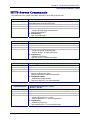
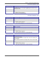
HTTP Server Commands ........................................................................................................................ 47
SMTP Client Commands ......................................................................................................................... 49
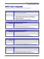
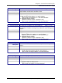
POP3 Client Commands ......................................................................................................................... 52
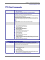
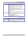
FTP Client Commands ............................................................................................................................ 55
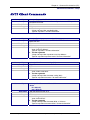
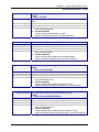
SNTP Client Commands ......................................................................................................................... 57
Chapter 5 – Setting Country or Region Codes Using the CLI .............................................................. 61
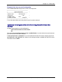
Chapter 6 – Prerequisite Configurations ................................................................................................ 62
Chapter 7 – Telnet Dialout........................................................................................................................ 65
Introduction.............................................................................................................................................. 65
Prerequisites............................................................................................................................................ 65
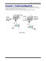
Scenario 1 – Manual Dialout ................................................................................................................... 67
Scenario 2 – Auto Dialout........................................................................................................................ 69
Scenario 3 – Auto Dialout in RAW Mode ................................................................................................ 71
Chapter 8 – Auto Dial-in Feature ............................................................................................................. 73
Introduction.............................................................................................................................................. 73
Prerequisites............................................................................................................................................ 73
Scenario 1 – Manual Serial Dial-in .......................................................................................................... 74
Scenario 2 – Serial Auto Dial-in in Telnet Mode ..................................................................................... 76
Scenario 3 – Auto Dial-in Session in RAW Mode ................................................................................... 78
Scenario 4 – Serial Tunneling Mode ....................................................................................................... 79
Chapter 9 – Modem (Transparent) Mode ................................................................................................ 81
Introduction.............................................................................................................................................. 81
Scenario 1 – MultiConnect IP as a Modem ............................................................................................. 82
Scenario 2 – Serial Tunneling in Transparent Mode............................................................................... 83
Multi-Tech Systems, Inc. MultiConnect Serial-to-Serial Adapter User Guide (S000354A)
3
Table of Contents
Chapter 10 – Modem Mode AT Commands, S-Registers, Result Codes............................................. 85
Escape Code Sequence +++ .................................................................................................................. 85
Command Organization........................................................................................................................... 85
Command Types ..................................................................................................................................... 86
Command Detail...................................................................................................................................... 88
FastConnect Commands....................................................................................................................... 114
V.92 Commands (+P and –Q Commands) ........................................................................................... 115
S-Registers............................................................................................................................................ 118
Result Codes ......................................................................................................................................... 127
Chapter 11 – Point-to-Point Protocol .................................................................................................... 132
Introduction............................................................................................................................................ 132
Components of PPP .............................................................................................................................. 132
Prerequisites for Establishing a PPP Session....................................................................................... 132
Adding Users and Passwords............................................................................................................ 132
Setting Passwords ............................................................................................................................. 133
Deleting Users ................................................................................................................................... 133
Notes.................................................................................................................................................. 133
PPP Configuration ................................................................................................................................. 133
PPP Interface Related Parameters ....................................................................................................... 134
Enabling/Disabling Authentication ..................................................................................................... 134
Authentication Type - Protocol........................................................................................................... 134
User Name & Password for Remote Peer Authentication ................................................................. 134
IPCP Mode......................................................................................................................................... 134
Show Commands............................................................................................................................... 134
Serial Interface Related Parameters ..................................................................................................... 135
Connect Type..................................................................................................................................... 135
Modem Settings - For Modem Connection Only ............................................................................... 135
Chapter 12 – HTTP Server ...................................................................................................................... 136
Introduction............................................................................................................................................ 136
Setup and Configuration........................................................................................................................ 137
Prerequisite for Enabling the HTTP Server ....................................................................................... 137
Mandatory Setup for HTTP Server .................................................................................................... 137
Configuration Modes ............................................................................................................................. 138
Host Configuration Mode....................................................................................................................... 138
The Parameter List ............................................................................................................................ 138
The Embedded HTML Page .............................................................................................................. 140
CGI Scripts......................................................................................................................................... 140
File Naming and File Size Conventions............................................................................................. 140
Uploading the Web Page and Parameter List ................................................................................... 141
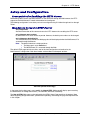
Monitoring and Configuring the Host through a Browser ...................................................................... 142
Technical Information ............................................................................................................................ 142
Parameter Value Display on the Fly .................................................................................................. 142
Parameter Value Manipulation from the Browser.............................................................................. 142
Serial Device Parameter Updating Process ...................................................................................... 142
Chapter 13 – SMTP Client....................................................................................................................... 143
Introduction............................................................................................................................................ 143
Setup and Configuration Prerequisites.................................................................................................. 144
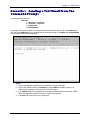
Scenario 1 – Sending a Text Email from the Command Prompt .......................................................... 145
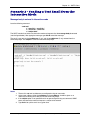
Scenario 2 – Sending a Text Email from the Interactive Mode ............................................................. 146
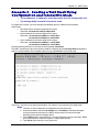
Scenario 3 – Sending a Text Email Using Configuration and Interactive Mode ................................... 147
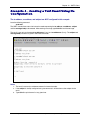
Scenario 4 – Sending a Text Email Using No Configuration................................................................. 148
Scenario 5 – Sending a Mime Encoded Binary Attachment Using Command Prompt......................... 149
Scenario 6 – Sending a Mime Encoded Binary Attachment Using the Command Prompt................... 150
Scenario 7 – Sending a Mime Encoded Binary Attachment Using Configuration and Interactive Mode151
Scenario 8 – Sending a Mime Encoded Binary Email with Attachment Using Interactive Mode.......... 152
Multi-Tech Systems, Inc. MultiConnect Serial-to-Serial Adapter User Guide (S000354A)
4
Table of Contents
Chapter 14 – POP3 Client ....................................................................................................................... 153
Introduction............................................................................................................................................ 153
Setup and Configuration Prerequisites.................................................................................................. 153
Optional Configuration for Deleting Emails from the Server.............................................................. 154
Scenario 1 – Retrieving Emails ............................................................................................................. 155
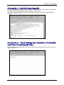
Scenario 2 – Retrieving the Number of Emails and the Total Email Size ............................................. 155
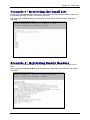
Scenario 3 – Retrieving the Email List .................................................................................................. 156
Scenario 4 – Retrieving Emails Headers............................................................................................... 156
Scenario 5 – Retrieving First t Lines ..................................................................................................... 157
Scenario 6 – Deleting an Email on the Server ...................................................................................... 157
Scenario 7 – Retrieving the Unique Email ID ........................................................................................ 157
Error Messages.................................................................................................................................. 158
Scenario 8 – Sending a Mime Encoded Binary Email Using Interactive Mode..................................... 159
Chapter 15 – FTP Client.......................................................................................................................... 160
Introduction............................................................................................................................................ 160
FTP Client Features........................................................................................................................... 160
Command to List Directory Contents or to Send/Receive Files ........................................................ 160
Prerequisites ...................................................................................................................................... 161
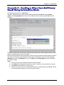
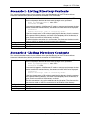
Scenario 1 - Listing Directory Contents................................................................................................. 162
Scenario 2 - Listing Directory Contents................................................................................................. 162
Scenario 3 - Listing Directory Contents................................................................................................. 163
Scenario 4 - Listing Directory Contents................................................................................................. 163
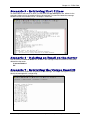
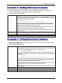
Scenario 5 - Sending a File to the FTP Server ..................................................................................... 164
Scenario 6 - Sending a File to the FTP Server ..................................................................................... 164
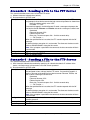
Scenario 7 - Sending a File to the FTP Server ..................................................................................... 165
Scenario 8 - Receiving a File from the FTP Server............................................................................... 165
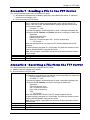
Scenario 9 - Receiving a File from the FTP Server............................................................................... 166
Scenario 10 - Receiving a File from the FTP Server............................................................................. 167
Chapter 16 – SNTP Client ....................................................................................................................... 168
Introduction............................................................................................................................................ 168
Features............................................................................................................................................. 168
Prerequisites.......................................................................................................................................... 168
Scenario 1 - Updating Time from the NTP Server ................................................................................ 170
Scenario 2 - Updating Time from the NTP Server ................................................................................ 170
Appendix A – Flash Upgrade ................................................................................................................. 171
Introduction............................................................................................................................................ 171
Prerequisites.......................................................................................................................................... 171
Prerequisite 1 – Required Tool (TFTP Client) ................................................................................... 171
Prerequisite 2 – Serial Port Configuration ......................................................................................... 172
Prerequisite 3 – Enabling TFTP Server ............................................................................................. 172
Serial Flash Upgrade Scenario ............................................................................................................. 172
Appendix B – Regulatory Information .................................................................................................. 173
Appendix C – Warranty and Service ..................................................................................................... 174
Multi-Tech Warranty Statement ......................................................................................................... 174
Repair Procedures for U.S. and Canadian Customers...................................................................... 174
Repair Procedures for International Customers (Outside U.S.A. and Canada) ................................ 174
Repair Procedures for International Distributors ............................................................................... 175
Replacement Parts ............................................................................................................................ 175
Index ......................................................................................................................................................... 176
Multi-Tech Systems, Inc. MultiConnect Serial-to-Serial Adapter User Guide (S000354A)
5
Chapter 1 – Product Description and Specifications
Chapter 1 – Product Description &
Specifications
Product Description
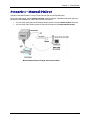
The MultiConnect serial-to-serial adapter enables installed serial devices to connect to the Internet for
remote monitoring, control and configuration.
Internet-Enable Any Device. The MultiConnect adapter provides the powerful ability to IP-enable serial
devices allowing more options for data acquisition, device management, and industrial control than would
otherwise be available.
Simply install the MultiConnect between a serial device and an analog, ISDN, or wireless modem to send
and receive data over the Internet. It can also serve as a single Web page in response to a Web browser
request.
Reduces Development Time. MultiConnect can make your existing and next generation serial device
IP-ready without requiring hardware changes to its design. MultiConnect actually provides faster time-tomarket because it relieves the burden and expense of writing and maintaining Internet applications. The
complete, ready-to-integrate MultiConnect adapter allows you to enhance your product while you focus on
developing its core features.
Management and Configuration. MultiConnect has several means of management and configuration
built into the design. It supports remote configuration, which means you can have central site setup and
control of the remote adapters via the command line interface or telnet.
Applications
The MultiConnect adapters will IP-enable any device to provide remote monitoring, control and
configuration of any system. The solution is ideal for the following applications:
•
Appliances
•
ATM terminals
•
Credit card and check verification systems
•
Data collection
•
Gas pumps
•
Industrial and medical remote monitoring systems
•
Point-of-sale terminals
•
Remote diagnostics
•
Remote metering
•
Security systems
•
Ticketing machines
•
Vending/gaming machines
•
And more…..
Multi-Tech Systems, Inc. MultiConnect Serial-to-Serial Adapter User Guide (S000354A)
6
Chapter 1 – Product Description and Specifications
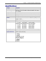
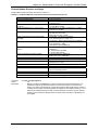
Types of Adapters Available
Product
Adapter Description
Region
MTS2SA-T
Serial-to-Serial + IP (External Power)
Global
MTS2SA-T-R
Serial-to-Serial + IP (RS-232 Power)
Global
Note: The RS-232–powered adapters are powered through the DSR pin of the
RS-232 cable.
Package Contents
•
One MultiConnect Adapter
•
One universal power supply with power cord included with the externally powered adapters
•
One RS-232 cable included with the RS-232 Serial-to-Serial Adapter
•
Two mounting brackets
•
Four adhesive-backed rubber feet (table-top mounting)
•
One Quick Start Guide
•
One MultiConnect CD
Handling Precautions
All devices must be handled with certain precautions to avoid damage due to the accumulation of static
charge. Although input protection circuitry has been incorporated into the devices to minimize the effect of
this static buildup, proper precautions should be taken to avoid exposure to electrostatic discharge during
handling and mounting.
Multi-Tech Systems, Inc. MultiConnect Serial-to-Serial Adapter User Guide (S000354A)
7
Chapter 1 – Product Description and Specifications
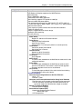
Specifications
Category
Memory
Flash Memory
Protocols Supported
Description
8 MEG
2 MEG
ARP, DHCP, FTP, HTTP, ICMP, IP, POP3, PPP, SMTP, TCP, Telnet,
TFTP, and UDP
Standard DCE serial
Serial Interface
Serial, binary, asynchronous
Data Formats
300; 1200; 2400; 4800; 9600; 19200; 38400; 57600; 115200; 230400 bps
Data Rates
RTS/CTS (hardware)
Flow Control
Serial; Telnet
Management
Username and password authentication using local database
Security
Flash ROM standard: downloadable from a TCP/IP host (TFTP) or
System Software
Xmodem via Serial
ACT (Activity) and STS (Status)
LEDs
IEEE 802.3
Ethernet
Power Requirements
With External Power (MTS2SA-T) Power Consumption
@ 9V DC:
Typical 240mA
Maximum 250mA
With RS-232 Power (MTS2SA-T-R) Power Consumption
@ 5V DC:
Typical 95mA
Maximum 105mA
@ 10V DC:
Typical 50mA
Maximum 60mA
@ 15V DC:
Typical 35mA
Maximum 45mA
@ 20V DC:
Typical 28mA
Maximum 38mA
@ 25V DC:
Typical 24mA
Maximum 34mA
Operating Temperature 32° to +120°F (0° to 50°C); humidity range 25-85% (non-condensing)
Storage Temperature
-40°C to +85°C
3.5" w x 2.1" h x 0.98" d; 3.4 oz.
Physical Dimensions
8.8 cm x 5.3 cm x 6 cm; 96 g
Certifications
Safety Certifications:
UL60950
cUL60950
EN60950
ACA TS001 / AS 3260
EMC Safety Approvals:
FCC Part 15 Class A
EN55022
EN55024
CE Marked
Multi-Tech Systems, Inc. MultiConnect Serial-to-Serial Adapter User Guide (S000354A)
8
Chapter 1 – Product Description and Specifications
Category
Intelligent Features
Software Features
Description
High performance 10/100BaseT Ethernet bridge
Half duplex or full duplex support on the WAN interface
256 frame buffer
Stores 10,000 MAC addresses
Automatically learns MAC addresses
Serial interface supports DTE speeds to 230K bps
External and RS-232 power options
High performance processor runs ARP, DHCP, FTP, HTTP, ICMP, IP,
POP3, PPP, SMTP, SNMP, SNMP, TCP, Telnet, TFTP, UDP protocols
Command line interface
Flash memory to update firmware with the latest enhancements
Flexible IP protocol stack
Compact, rugged industrial chassis design
Desktop or panel mounting
Two-year warranty
Internet Applications
DHCP Client:
Request IP address for Ethernet Interfaces
Telnet Server:
Command Line Configuration
Auto Dial-out Feature
Command line via custom port (other than standard port 23)
Telnet Client:
Connect to remote Telnet Server
Serial Auto Dial-in Feature
Terminal Server:
Network to Serial Connectivity
Serial to Network Connectivity
TFTP Server:
Flash Upgrade
SMTP Client:
The email client embedded in the MultiConnect sends email to the
configured recipients.
POP3 Client:
The email client embedded in the MultiConnect receives email
from the POP3 Server. This feature is useful for field upgrades.
Firmware upgrades can be sent as attachments.
HTTP Server:
To host Web pages on behalf of the serial device for monitoring
and configuration of the serial device.
Functional Features
Command Line Configuration over Serial or Ethernet
Serial - TTY
Ethernet - Telnet
Username and Password Authentication Using Local Database
The Username and Password can be created using commands.
The User database authenticates the Users before access to
command mode of the MultiConnect adapter is enabled.
Remote Transparent Bridging
Ethernet to Serial Bridging
Point-to-Point Protocol (PPP)
Negotiations Bridging Control Protocol
- 802.3 MAC Type
CCP Compression
Multi-Tech Systems, Inc. MultiConnect Serial-to-Serial Adapter User Guide (S000354A)
9
Chapter 1 – Product Description and Specifications
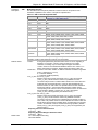
LED Indicators
Name
ACT
STS
Description
Activity – Lit when data is being transmitted or received.
Status – Blinks to indicate that the unit is functioning.
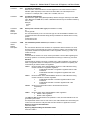
RS-232 9-Pin Connector Pinout
Pin 1
Pin 6
Pin 5
Pin 9
Pins for the Serial-to-Serial Adapter when Power Is Supplied Externally
Pin
1
2
3
4
5
6
7
8
9
Description
DCD
RX Data
TX Data
DTR
Ground
DSR
RTS
CTS
RI
Pins for the Serial-to-Serial Adapter when Power Is Supplied Through the RS-232 Pin
Pin
1
2
3
4
5
6
7
8
9
Description
DCD
RX Data
TX Data
DTR
Ground
Power
RTS
CTS
RI
Multi-Tech Systems, Inc. MultiConnect Serial-to-Serial Adapter User Guide (S000354A)
10
Chapter 2 – Installation
Chapter 2 – Installation
Attaching the MultiConnect to a Fixed
Location
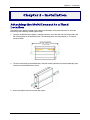
The MultiConnect adapter is design to be used on the desktop or to be panel-mounted. To attach the
bracket for panel-mounting, following these steps:
1. Typically, the MultiConnect adapter is mounted against a flat surface with two mounting screws. Drill
the mounting holes at the desired location. The mounting holes must separated by 4 -7/16 inches
center-to-center.
2. To attach the brackets to the MultiConnect, slide the mounting brackets into the corresponding slots
on the back of the MultiConnect chassis.
3. Attach the adapter to the surface with two screws.
Multi-Tech Systems, Inc. MultiConnect Serial-to-Serial Adapter User Guide (S000354A)
11
Chapter 2 – Installation
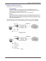
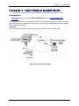
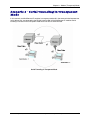
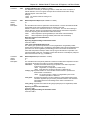
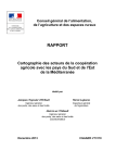
Serial-to-Serial Adapter Installation
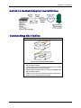
Connecting the Cables
Serial-to-Serial Adapter
Front
Back shown with External Power Option
1. Plug one end of the RS-232 cable into the front of the
Serial-to-Serial adapter.
Plug the other end into the RS-232 connector on the modem
that is setup with an Internet connection.
2. Plug one end of the other RS-232 cable into the back of the
Serial-to-Serial adapter.
Plug the other end into the RS-232 connector on the serial
device you want connected to the Internet.
Multi-Tech Systems, Inc. MultiConnect Serial-to-Serial Adapter User Guide (S000354A)
12
Chapter 2 – Installation
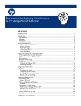
Connecting the Power
The adapters are powered in one of two ways:
•
Through the DSR Pin of the RS-232 Cable
Adapters powered this way are shipped with an RS-232 cable that has a power pin instead of a
DSR pin.
•
Through an External Power Supply
Adapters powered this way are shipped with a universal power supply and its accompanying power
cord and an RS-232 cable that has a DSR pin instead of a power pin.
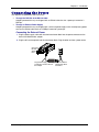
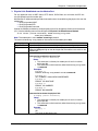
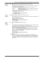
Connecting the External Power
1. Plug the power supply cable with attached transformer block into the power connector on the
back of the MultiConnect adapter.
2. Plug the AC cord receptacle into the transformer block. Plug the other end into a power outlet.
One end of
RS-232
Shown
Here
Plug Power Supply Cable with Plug AC Cord into
Transformer Block
Transformer into the Back of
and Outlet
the Adapter
Multi-Tech Systems, Inc. MultiConnect Serial-to-Serial Adapter User Guide (S000354A)
13
Chapter 3 – Managing and Configuring the MultiConnect Adapter
Chapter 3 – Managing and
Configuring the MultiConnect
Adapter
Two Ways to Login
Login Using TTY
•
Use TTY to configure your MultiConnect IP for the first time. Configure the host serial port
using the defaults listed below:
Baud: 115.2K
Data: 8
Parity: N
Stop: 1
Flow-Control: None
•
Press the Enter key three times to get to the Login prompt or send three carriage returns.
•
At the Login prompt, type admin.
At the Password prompt, type admin.
Important: The user name and password are case sensitive. They must be typed in lowercase
letters.
Login Using Telnet through the PPP Interface
•
Open the PPP interface on the modem port.
•
Upon successful establishment of a Telnet session, the MultiConnect IP displays the Login
prompt.
At the Login prompt, type admin.
At the Password prompt, type admin.
•
After a successful login, the MultiConnect IP enters Command Mode. In Command Mode,
the MultiConnect IP can be configured and managed using the Command Line Interface
(CLI) command set.
About Command Mode and Data Mode
• In Command Mode, a # sign designates the prompt. If you type the word Help at the command
prompt, a complete list of commands displays.
• If you type the word Usage at the command prompt, a list of the command semantics displays.
• In Data Mode, the # sign is not displayed.
• To leave Command Mode, exit your terminal or Telnet session or type the word Exit at the
command prompt.
Note: See the Restore command and IP Escape String command.
Multi-Tech Systems, Inc. MultiConnect Serial-to-Serial Adapter User Guide (S000354A)
14
Chapter 4 – Command Line Interface (CLI)
Chapter 4 – Command Line Interface
(CLI)
The MultiConnect commands are grouped based on the functionality.
•
General Setup Commands
•
IP Setup Commands
•
Serial Setup Commands
•
PPP Setup Commands
•
HTTP Setup Commands
•
SMTP Setup Commands
•
POP3 Setup Commands
•
FTP Client Setup Commands
•
SNTP Client Setup Commands
General Notes
•
Required command parameters are indicated between < >.
•
Optional command parameters are indicated between [ ].
•
Parameter choices are delineated by /.
•
Upon successful execution of a command, the “OK” string is echoed to the client.
•
When an unsuccessful command is executed, an appropriate error message is displayed
followed by an "ERROR" string.
•
All the commands are case sensitive (they must be typed in lower case).
•
PPP is enabled on the modem interface S1.
•
All serial-related applications such as dial-in and dial-out are with respect to the serial
interface S0.
•
The PPP interface is the modem interface S1.
Multi-Tech Systems, Inc. MultiConnect Serial-to-Serial Adapter User Guide (S000354A)
15
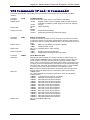
Chapter 4 – Command Line Interface (CLI)
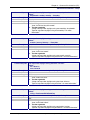
General Commands – Setup
General Setup Commands
General setup of a MultiConnect IP is port-independent (physical S0, S1 etc.). The following command
set is used to set the global configuration of MultiConnect IP.
Command Syntax
Description
Default Value
Success
Error
Command Syntax
Description
Default Value
Success
Command Syntax
Description
Default Value
Success
Command Syntax
Description
Default Value
Success
Error
Command Syntax
Description
Default Value
Success
Error
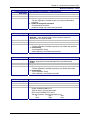
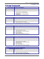
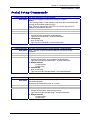
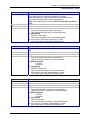
dialout serial s0
Manual Telnet dialout (Internet-to-serial connectivity).
Invoked from the command shell.
NA
OK
1. Too few arguments
“Usage: dialout serial <serial port>
Type ‘dialout ?’ for more information”
2. Invalid argument
Possible argument(s) are: Serial
1. When invoked from Serial Shell
This command is not supported through serial dial-in
Exit
Exits the command parser, unlocks the configurations, terminates session.
NA
OK
Help
Provides the first level of commands in MultiConnect IP.
NA
OK
restore default-config
Restores the factory defaults.
Note: All previous configurations will be lost upon invoking this command.
The changes are made permanent only if save config is invoked.
NA
OK
1. Too few arguments
”Possible arguments are default-config and session
2. Invalid argument
Invalid argument “invalid string”
Valid arguments are default-config and session
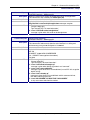
restore session
On Telnet dialout, the control is transferred to the command parser passing
the escape sequence “+++ inet”. Invoking “restore session” would resume
the Telnet dialout exiting the command parser.
NA
OK
1. Too few arguments
Possible arguments are default-config and session
2. ERROR: Session not opened
Multi-Tech Systems, Inc. MultiConnect Serial-to-Serial Adapter User Guide (S000354A)
16
Chapter 4 – Command Line Interface (CLI)
General Commands – Setup
Command Syntax
Description
Default Value
Success
Error
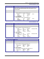
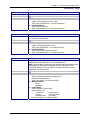
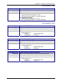
reset modem
At will, reset the built-in modem.
NA
OK
1. Too few arguments
Possible argument(s) are modem
Command Syntax
Description
Default Value
Success
save
Command to Save the configuration to the flash and reboot.
NA
OK
Command Syntax
Description
telnet <dial-ip-addr> [<port>]
Manual serial dial-in (device port to modem port connectivity).
Invoked from the command shell.
NA
OK
1. Too few arguments
2. Invalid IP address/Port
“(Error: hostp = “configured host“. Error: hostp=“configured IP address“
3. When invoked from Command shell connected through Telnet
This command is not supported through Telnet
Default Value
Success
Error
Command Syntax
Description
Default Value
Success
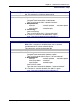
Usage
Provides the command semantics for all the commands.
NA
OK
Command Syntax
Description
user add <user-name> [<passwd>]
Add the user name and the password to the group.
Notes: Default Groups: admin, users
Default Users: admin, ipmodule
Only Admin can configure the MultiConnect IP
NA
OK
1. Too few arguments
“Too few arguments. Possible value(s) are username followed by
password“
2. Unable to add the user name: “user ‘username‘ exists“
Default Value
Success
Error
Command Syntax
Description
Default Value
Success
Error
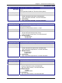
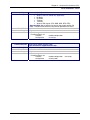
user delete <user-name>
Delete the user name from the group.
NA
OK
1. Too few arguments
“Too few arguments. Possible value(s) are username followed by
password“
2. Unable to delete the user name: “user ‘username‘ does not exist“
Multi-Tech Systems, Inc. MultiConnect Serial-to-Serial Adapter User Guide (S000354A)
17
Chapter 4 – Command Line Interface (CLI)
General Commands – Setup
Command Syntax
Description
Default Value
Success
Error
Command Syntax
Description
Default Value
Success
Error
Command Syntax
Description
Default Value
Success
Error
Command Syntax
Description
Default Value
Success
Error
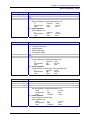
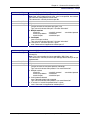
user password <username> <new password>
Change the password for a user.
NA
OK
1. Too few arguments
“Too few arguments. Possible value(s) are username followed by
password”
2. Unable to change the password
“Password does not match
Unable to change user <username> password”
set operation-mode <modem/ipmodule>
modem - In the modem mode, the target functions like a modem
ipmodule - In the ipmodule mode, all the functional features of
MultiConnect IP can be achieved.
Ipmodule
OK
1. Too few arguments
"Too few arguments. Possible argument(s) are modem and ipmodule
2. Invalid string
"Invalid argument "string"
Valid argument(s) are modem and ipmodule
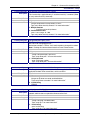
set boot-messages <enable/disable>
enable - Prints the boot-messages during module boot-up.
disable - Suppresses the boot-messages during module boot-up.
Enable
OK
1. Too few arguments
"Too few arguments. Possible argument(s) are disable and enable
2. Invalid string
"Invalid argument "string"
Valid argument(s) are disable and enable
set date <DD/MM/YYYY>
Sets the system date.
Jan 1 1970
OK
1. Too few arguments
Usage: set date DD/MM/YYYY
Type 'set date ?' for more information
Error: Date in DD/MM/YYYY format
Too few arguments. Possible argument(s) are
ip
ppp
date
serial
login
time
Multi-Tech Systems, Inc. MultiConnect Serial-to-Serial Adapter User Guide (S000354A)
18
Chapter 4 – Command Line Interface (CLI)
General Commands – Setup
Command Syntax
Description
Default Value
Success
Error
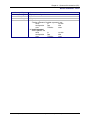
set login
Prompts the Login for the command shell when enabled, and doesn't when
disabled.
Enable
OK
1. Too few arguments
"Usage: set login <enable/disable>
Type 'set login ?' for more information"
2. Invalid string
"error: set login <enable/disable>"
Command Syntax
Description
Default Value
Success
Error
set login auto-dialout-login <enable/disable>
Enables/Disables authentication for Telnet auto-dialout.
Disable
OK
1. Too few arguments
"Usage: set login auto-dialout-login <enable/disable>
Type 'set login auto-dialout-login ?' for more information"
2. Invalid string
"error: set login auto-dialout-login <enable/disable>"
Command Syntax
Description
Default Value
Success
Error
set time <HH:MM:SS>
Sets the system time.
00:00:00
OK
1. Too few arguments
Usage: set date HH:MM:SS
Type 'set date ?' for more information
Error: Time in HH:MM:SS format
Too few arguments. Possible argument(s) are
ip
login
serial
date
ppp
time
Command Syntax
Description
Default Value
Success
Error
set watchdog <enable/disable>
Enables/Disables the watchdog timer.
The timer value is set to 6.5 seconds. This is the upper threshold value.
Note: Watchdog timer comes into effect only after reboot. Hence,
invoking this command calls for a reboot on save.
Enable
OK
1. Too few arguments
"Usage: set watchdog <enable/disable>
Type 'set watchdog <enable/disable> ?' for more information"
2. Invalid string
"error: set watchdog <enable/disable>"
Multi-Tech Systems, Inc. MultiConnect Serial-to-Serial Adapter User Guide (S000354A)
19
Chapter 4 – Command Line Interface (CLI)
General Commands – Setup
Command Syntax
Description
Default Value
Success
Error
show buildrun
Command Line Configuration - History.
Upon invoking any command, either through Telnet or Serial TTY, the
command is added to the buildrun file. This is very useful in case of
version updates.
NA
OK
1. Too few arguments
"Too few arguments. Possible argument(s) are
serial
date
statistics
users
buildrun
ip
sys-info
configuration
ppp
time
2. Invalid argument
Invalid argument "string". Valid arguments are
serial
date
statistics
users
buildrun
ip
sys-info
configuration
ppp
time
General Commands – Show
Command Syntax
Description
Default Value
Success
Error
Command Syntax
Description
Default Value
Success
Error
show configuration
Displays the MultiConnect IP configuration.
NA
OK
1. Too few arguments
“Too few arguments. Possible argument(s) are:
serial
ppp
sys-info
configuration
recv-mail
time
date
http
users
buildrun
statistics
send-mail
2. Invalid argument
Valid arguments are:
serial
ppp
sys-info
configuration
recv-mail
time
date
http
users
buildrun
statistics
send-mail
device-parameter
device-parameter
show date
Shows the system date.
NA
OK
1. Too few arguments
Too few arguments. Possible argument(s) are:
ip
statistics
users
configuration
ppp
sys-info
date
serial
time
2. Invalid argument
Invalid argument "Invalid string". Valid arguments are
ip
statistics
users
configuration
ppp
sys-info
date
serial
time
Multi-Tech Systems, Inc. MultiConnect Serial-to-Serial Adapter User Guide (S000354A)
20
Chapter 4 – Command Line Interface (CLI)
General Commands – Show
Command Syntax
Description
Default Value
Success
Error
show statistics
Displays MultiConnect IP statistics.
NA
OK
1. Too few arguments
“Too few arguments. Possible argument(s) are:
ip
statistics
users
configuration
ppp
sys-info
date
serial
time
2. Invalid argument
Valid arguments are:
ip
statistics
users
configuration
ppp
sys-info
date
serial
time
Command Syntax
Description
show sys-info
Displays the system related information.
• Hardware information
• System Uptime
• Memory Utilization
• Flash Memory Map
NA
OK
1. Too few arguments
Too few arguments. Possible argument(s) are:
ip
statistics
users
configuration
ppp
sys-info
date
serial
time
2. Invalid argument
Invalid argument "Invalid string". Valid arguments are:
ip
statistics
users
configuration
ppp
sys-info
date
serial
time
Default Value
Success
Error
Command Syntax
Description
Default Value
Success
Error
show time
Displays the system time.
NA
OK
1. Too few arguments
Too few arguments. Possible argument(s) are
serial
ip
sys-info
configuration
ppp
time
date
statistics
users
2. Invalid argument
Invalid argument "Invalid string"
Valid arguments are:
serial
ip
sys-info
configuration
ppp
time
date
statistics
users
Multi-Tech Systems, Inc. MultiConnect Serial-to-Serial Adapter User Guide (S000354A)
21
Chapter 4 – Command Line Interface (CLI)
General Commands – Show
Command Syntax
Description
Default Value
Success
Error
show users
Displays the configured users.
NA
OK
1. Too few arguments
“Too few arguments. Possible argument(s) are:
serial
ip
sys-info
configuration
ppp
time
date
statistics
users
2. Invalid argument
Valid arguments are:
serial
ip
sys-info
configuration
ppp
time
date
statistics
users
Multi-Tech Systems, Inc. MultiConnect Serial-to-Serial Adapter User Guide (S000354A)
22
Chapter 4 – Command Line Interface (CLI)
IP Commands – Setup
IP Setup Commands
Command Syntax
Description
Default Value
Success
Error
set ip dns <enable/disable>
Enables/disables the DNS client.
Enabled
OK
1. Too few arguments
“Usage: set ip dns <enable/disable>
Type ‘set ip dns ?’ for more information”
2. Invalid string
Type ‘set ip dns ?’ for more information”
Command Syntax
Description
Default Value
Success
Error
set ip hostname <hostname>
Sets the host name of the MultiConnect IP.
“MultiConnectIP”
OK
1. Too few arguments
“Usage: set ip hostname <hostname>
Type ‘set ip hostname ?’ for more information”
Command Syntax
Description
Default Value
Success
Error
set ip pri-dns <ip addr>
Sets the primary DNS IP address to 0.0.0.0.
0.0.0.0
OK
1. Too few arguments
“Usage: set ip pri-dns <ip addr>
Type ‘set ip pri-dns ?’ for more information”
2. Invalid IP Address
“error: Invalid IP address
Type ‘set ip pri-dns ?’ for more information”
Command Syntax
Description
Default Value
Success
Error
set ip sec-dns <ip addr>
Sets the secondary DNS IP address to 0.0.0.0.
0.0.0.0
OK
1. Too few arguments
“Usage: set ip sec-dns <ip addr>
Type ‘set ip sec-dns ?’ for more information”
2. Invalid IP Address
“error: Invalid IP address
Type ‘set ip sec-dns ?’ for more information”
Command Syntax
Description
Default Value
Success
Error
set ip syslogd <enable/disable>
Enables/Disables syslogd.
Disable
OK
1. Too few arguments
“Usage: set ip syslogd <enable/disable>
Type ‘set ip syslogd ?’ for more information”
Multi-Tech Systems, Inc. MultiConnect Serial-to-Serial Adapter User Guide (S000354A)
23
Chapter 4 – Command Line Interface (CLI)
IP Commands – Setup
Command Syntax
Description
Default Value
Success
Error
set ip syslogd-server <ip addr>
Sets the remote syslog server's IP address.
0.0.0.0
OK
1. Too few arguments
“Usage: set ip syslogd-server <ip_addr>
Type ‘set ip syslogd-server ?’ for more information”
2. Invalid IP address
“error: Invalid IP address
Type ‘set ip syslogd-server ?’ for more information”
Command Syntax
Description
set ip tcp-keepalive <t mins>
Sets the TCP keep-alive timeout for the MultiConnect IP.
't' : range from 3-120 minutes
3 minutes
OK
1. Too few arguments
“Usage: set ip tcp-keepalive <t mins>
Type ‘set ip tcp-keepalive ?’ for more information”
2. Invalid IP address
“error: Invalid value, rante [3-120] mins
Type ‘set ip tcp-keepalive ?’ for more information”
Default Value
Success
Error
Command Syntax
Description
Default Value
Success
Error
set ip telnet <enable/disable>
Enables/disables the Telnet Server. This is a global setting, which will
enable/disable the Telnet Server in the MultiConnect IP.
Note: Upon disabling Telnet server, the administrator cannot configure the
MultiConnect IP over the built-in Modem interface (wherein PPP has
acquired IP Address). The only option is to connect through a terminal
application over the Serial port.
Enabled
OK
1. Too few arguments
Too few arguments. Possible argument(s) are
set ip telnet<enable/disable>
Type : set ip telnet ? for more information)
2. Multiple matches
telnet
telnet-port
3. Invalid String
Invalid argument "invalid string"
Valid arguments are
auto-dialout
escape-string
inactivity
inactivity-timeout
escape-monitor
raw-mode
Possible value(s) are enable or disable
Multi-Tech Systems, Inc. MultiConnect Serial-to-Serial Adapter User Guide (S000354A)
24
Chapter 4 – Command Line Interface (CLI)
IP Commands – Setup
Command Syntax
Description
Default Value
Success
Error
Command Syntax
Description
Default Value
Success
Error
set ip telnet auto-dialout <enable/disable>
Enables Telnet connectivity between the MultiConnect IP and the remote
device.
This flag enables/disables the Telnet Auto dialout globally.
Enabled
OK
1. Too few arguments
“Usage: set ip telnet auto-dialout <enable/disable>
Type ‘set ip telnet auto-dialout ?’ for more information”
2. Invalid String
Type ‘set ip telnet auto-dialout ?’ for more information”
set ip telnet escape-string <string>
The Telnet Server scans for this escape sequence and transfers the control
to the command parser.
By default, the Telnet Server scans for “+++inet”.
+++ inet
OK
1. Too few arguments
“Usage: set ip telnet escape-string <string>
Type ‘set ip telnet escape-string ?’ for more information”
2. Multiple matches
escape-monitor
escape-string
Command Syntax
Description
Default Value
Success
Error
set ip telnet escape-monitor <enable/disable>
Enables/disables the ‘‘monitor’’ flag that scans for the escape sequence.
Enabled
OK
1. Too few arguments
“Usage: set ip telnet escape-monitor <enable/disable>
Type ‘set ip telnet escape-monitor ?’ for more information”
2. Multiple matches
escape-monitor
escape-string
3. Invalid String
Type ‘set ip telnet escape-monitor ?’ for more information”
Command Syntax
Description
Default Value
Success
Error
set ip telnet inactivity <enable/disable>
Enables/disables the inactivity functionality.
Disable
OK
1. Too few arguments
“Usage: set ip telnet inactivity <enable/disable>
Type ‘set ip telnet inactivity ?’ for more information”
2. Multiple matches
inactivity
inactivity-timeout
3. Invalid String
Type ‘set ip telnet inactivity ?’ for more information”
Multi-Tech Systems, Inc. MultiConnect Serial-to-Serial Adapter User Guide (S000354A)
25
Chapter 4 – Command Line Interface (CLI)
IP Commands – Setup
Command Syntax
Description
Default Value
Success
Error
Command Syntax
Description
Default Value
Success
Error
Command Syntax
Description
Default Value
Success
Error
Command Syntax
Description
Default Value
Success
Error
set ip telnet inactivity-timeout <t secs>
If the Telnet session is inactive for ‘t’ secs, the connection is terminated.
This functionality is applicable only if “set telnet inactivity” is enabled. (Refer
to ’set ip telnet inactivity’ command).
5 min
OK
1. Too few arguments
“Usage: set ip telnet inactivity-timeout <t secs>
Type ‘set ip telnet inactivity-timeout ?’ for more information”
2. Multiple matches
inactivity and inactivity-timeout
3. Invalid timeout value
“error: ‘t secs range : 0 – 300
Type ‘set ip telnet inactivity-timeout ?’ for more information”
set ip telnet-port <port_num >
This Telnet-port corresponds to the port number that the MultiConnect IP
will wait on for configuring the box.
Default port number is TCP 23. You have the option to change this number.
Note: Invoking this command terminates the current Telnet session.
23
OK
1. Too few arguments
“Usage: set ip telnet-port <port-num>
Type ‘set ip telnet-port ?’ for more information”
2. Invalid port-num
“error: Invalid port number
Type ‘set ip telnet-port ?’ for more information”
set ip telnet raw-mode <enable/disable>
This is a global setting of raw-mode for the Telnet application. This setting is
applicable for both Telnet auto-dialout, serial auto-dial-in.
Disabled
OK
1. Too few arguments
“Usage: set ip telnet raw-mode <enable/disable>
Type ‘set ip telnet raw-mode ?’ for more information”
2. Invalid String
ERROR
set ip tftp <enable/disable >
Enables/disables the TFTP Server. When the TFTP Server is enabled, the
network administrator can upload the firmware to the flash.
Enabled
OK
1. Too few arguments
“Usage: set ip tftp <enable/disable>
Type ‘set ip tftp ?’ for more information”
2. Invalid string
error: Invalid string
Type ‘set ip tftp ?’ for more information”
Multi-Tech Systems, Inc. MultiConnect Serial-to-Serial Adapter User Guide (S000354A)
26
Chapter 4 – Command Line Interface (CLI)
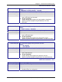
Serial Commands – Setup
Serial Setup Commands
Command Syntax
Description
Default Value
Success
Error
Command Syntax
Description
Default Value
Success
Error
Command Syntax
Description
Default Value
Success
Error
set serial auto-telnet <enable/disable>
This command globally enables serial auto dial-in support.
Notes:
This feature provides a Telnet session to the serial device connected to S0
through the IP-enabled modem port (S1)
Also, Telnet can be used only after PPP is up and has acquired an IP
address on the modem's (S1) port.
Disabled
OK
1. Too few arguments
“Usage: set serial auto-telnet <enable/disable>
Type ‘set serial auto-telnet ?’ for more information”
2. Invalid string
error: Invalid string
Type ‘set serial auto-telnet ?’ for more information
set serial <serial-interface> escape-monitor <enable/disable>
Sets a ‘‘monitor’’ flag that enables/disables the scanning of escape
sequence.
Enable
OK
1. Too few arguments
“Usage: set serial s0/s1 escape-monitor <enable/disable>
Type ‘set serial s0/s1escape-monitor ?’ for more information”
2. Multiple matches
escape-monitor
escape-string
3. Invalid string
error: Invalid string
Type ‘set serial s0/s1 escape-monitor ?’ for more information”
set serial <serial-interface> escape-string <string>
The Telnet client scans for this escape sequence and transfers the control to
the command parser.
By default, the Telnet client scans for “+++inet”.
+++ inet<serial-interface>
OK
1. Too few arguments
“Usage: set serial s0/s1 escape-string <string>
Type ‘set serial s0/s1 escape-string ?’ for more information”
2. Multiple matches
escape-monitor
escape-string
Multi-Tech Systems, Inc. MultiConnect Serial-to-Serial Adapter User Guide (S000354A)
27
Chapter 4 – Command Line Interface (CLI)
Serial Commands – Setup
Command Syntax
Description
Default Value
Success
Error
Command Syntax
Description
Default Value
Success
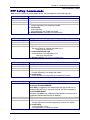
hangup [serial interface]
Valid serial interface – Modem port S1
When this command is issued, the established live link is brought down.
This command is only valid only for modem port (S1)
If physical link is brought down, OK and
Physical link is successfully brought down messages are given
1. Too few arguments
"Usage: hangup [S1]
Type 'hangup [S1] ?' for more information"
2. “error: Link could not be brought down”
message is given when link could not be brought down
linkup [serial interface]
Valid serial interface – Modem port S1
Establishes a physical link and PPP on the modem port.
This command is relevant only when the serial interface is a dialing end
with dialing-trig-mode configured as "command"
If physical link is established
OK and
CONNECT 14400 LAPM COMPRESSED
Error
(i.e., CONNECT message from the modem)
are given
1. Too few arguments
"Usage: linkup [S1]
Type 'linkup [S1]' for more information"
2. “error: Link cannot be brought up”
message is given when dialing-trig-mode is not "command”
3. “error: Link is not established”
message is given when link is not established (in case PPP fails to get the
logical link up)
4. “error: Link is already up”
message is given when link is established and this command will not
tear down and bring up the link
5. “error: NO CARRIER / NO DIALTONE / NO ANSWER”
or any error return code from the modem
Multi-Tech Systems, Inc. MultiConnect Serial-to-Serial Adapter User Guide (S000354A)
28
Chapter 4 – Command Line Interface (CLI)
Serial Commands – Setup
Command Syntax
Description
Default Value
Success
Error
Command Syntax
Description
Default Value
Success
Error
set serial [s0] auto-dialin <enable/disable>
Enables/disables the device port to Internet connectivity for the serial port
S0. This command is valid only for device port S0
Disabled
OK
1. Too few arguments
“Usage: set serial s0 auto-dialin <enable/disable>
Type ‘set serial s0 auto-dialin ? for more information”
2. Multiple matches
auto-dialin
auto-dialin-protocol
auto-dialout-protocol
auto-dialin-ipaddress
auto-dialout
auto-dialin-port
auto-dialout-port
3. Invalid string
“error: Invalid string
Type ‘set serial s0 auto-dial-in ? for more information”
4. If “set serial s1 auto-dialin <enable/disable>” is given
“error: Command not supported on the modem port s1”
set serial [s0] auto-dialin-ipaddress <ipaddr>
Specifies the auto dial-in IP address.
Note: When a connection is established from serial, a session is
established to the IP address mentioned above.
This command is valid only for device port S0.
NULL
OK
1. Too few arguments
“Usage: set serial s0 auto-dialin-ipaddress <ipaddr>
Type ‘set serial s0 auto-dialin-ipaddress ? for more information”
2. Multiple matches
auto-dialin
auto-dialin-protocol
auto-dialout-protocol
auto-dialin-ipaddress
auto-dialout
auto-dialin-port
auto-dialout-port
3. Invalid IP Address
“error: Invalid IP address
Type ‘show serial s0 auto-dialin-ipaddress ? for more information”
4. If “set serial s1 auto-dialin-ipaddress 192.168.2.2” is given
“error: Command not supported on the modem port s1”
Multi-Tech Systems, Inc. MultiConnect Serial-to-Serial Adapter User Guide (S000354A)
29
Chapter 4 – Command Line Interface (CLI)
Serial Commands – Setup
Command Syntax
Description
Default Value
Success
Error
Command Syntax
Description
Default Value
Success
Error
set serial [s0] auto-dialin-port [port_num]
Command to specify the auto dial-in port number.
Note: [port_num] is optional here. If port_num is not specified, the standard
port 23 of the Telnet protocol shall be used.
This command is valid only for device port S0
23
OK
1. Too few arguments
“Usage: set serial s0 auto-dialin-port [port_num]
Type ‘set serial s0 auto-dialin-port ? for more information”
2. Multiple matches
auto-dialin
auto-dialin-protocol
auto-dialout-protocol
auto-dialin-ipaddress
auto-dialout
auto-dialin-port
auto-dialout-port
3. Invalid port
“error: Invalid port number
Type ‘set serial s0 auto-dialin-port ? for more information”
4. If “set serial s1 auto-dialin-port 23” is given
“error: Command not supported on modem port s1”
set serial [s0] auto-dialin-protocol <telnet>
By default, Telnet is the protocol used to establish the serial-to-Internet
connectivity.
Note: This syntax provides for future extensibility (SSH Client, etc.)
This command is valid only for device port S0<ftp protocol setting is not yet
implemented>
Telnet
OK
1. Too few arguments
“Usage: set serial s0 auto-dialin-protocol <telnet/ftp>
Type ‘set serial s0 auto-dialin-protocol ? for more information”
2. Multiple matches
auto-dialin
auto-dialin-protocol
auto-dialout-protocol
auto-dialin-ipaddress
auto-dialout
auto-dialin-port
auto-dialout-port
3. Invalid protocol selected
“error: Selected protocol not supported
Type ‘set serial s0 auto-dialin-protocol ? for more information”
4. If “set serial s1 auto-dialin-protocol telnet” is given
“error: Command not supported on modem port s1”
Multi-Tech Systems, Inc. MultiConnect Serial-to-Serial Adapter User Guide (S000354A)
30
Chapter 4 – Command Line Interface (CLI)
Serial Commands – Setup
Command Syntax
Description
Default Value
Success
Error
Command Syntax
Description
Default Value
Success
Error
set serial [s0] auto-dialin trig-mode <char/ dtr/ dtr-char/ none>
This mode is applicable only when auto dial-in is enabled on the serial port
S0. This command is valid only for device port S0.
Parameter Description
char
Initiate a session (Telnet) to the auto-dialin-ipaddress, only on a reception
of a character on the serial port S0.
dtr
Initiate a session (Telnet) to the auto-dialin-ipaddress, only on seeing a
DTR signal on the serial port S0
dtr-char
Initiate a session (Telnet) to the auto-dialin-ipaddress, either on reception
of a character (OR) seeing the DTR signal on the serial port S0.
none
Initiate a Telnet session to the auto-dialin-ipaddress on module boot-up.
dtr-char
OK
1. Too few arguments
Too few arguments. Possible argument(s) are
char
dtr-char
dtr
none
2. Invalid string
“Invalid string "string"
Valid arguments are
char
dtr-char
dtr
none
3. If “set serial s1 auto-dialin trig-mode <char/dtr/dtr-char/none>” is given
“error: Command not supported on modem port s1”
set serial [s0] auto-dialout <enable/disable>
Enables/disables connectivity to the serial device from the IP-enabled builtin modem serial interface. This command is valid only for device port S0.
Enabled
OK
1. Too few arguments
“Usage: set serial s0 auto-dialout <enable/disable>
Type ‘set serial s0 auto-dialout ?’ for more information”
2. Multiple matches
auto-dialin
auto-dialin-protocol
auto-dialout-protocol
auto-dialin-ipaddress
auto-dialout
auto-dialin-port
auto-dialout-port
3. Invalid string
error: Invalid string
Type ‘set serial s0 auto-dialout ?’ for more information”
4. If “set serial s1 auto-dialout <enable/disable>” is given
“error: Command not supported on modem port s1”
Multi-Tech Systems, Inc. MultiConnect Serial-to-Serial Adapter User Guide (S000354A)
31
Chapter 4 – Command Line Interface (CLI)
Serial Commands – Setup
Command Syntax
Description
Default Value
Success
Error
Command Syntax
Description
Default Value
Success
Error
Command Syntax
Description
Default Value
Success
Error
set serial [s0] auto-dialout-port <port_num>
If auto-dialout is enabled, specifies the auto dialout-port on which the client
can connect.
Default is 5000.
Note: The port number should be other than standard TCP ports.
This command is valid only for device port S0.
5000
OK
1. Too few arguments
“Usage: set serial s0 auto-dialout-port <port_num>
Type ‘set serial s0 auto-dialout-port ? for more information”
2. Multiple matches
auto-dialin
auto-dialin-protocol
auto-dialout-protocol
auto-dialin-ipaddress
auto-dialout
auto-dialin-port
auto-dialout-port
3. Invalid Port Number
“error: Invalid port number
Type ‘set serial s0 auto-dialout-port ? for more information”
4. If “set serial s1 auto-dialout-port 5000” is given
“error: Command not supported on modem port s1”
set serial [s0] auto-dialout-protocol <telnet/>
Note:
This syntax gives a provision for future extensibility. <SSH Server, etc>.
This command is valid only for device port S0.
Telnet
OK
1. Too few arguments
“Usage: set serial s0 auto-dialout-protocol <telnet/>
Type ‘set serial s0 auto-dialout-protocol ?’ for more information”
2. Multiple matches
auto-dialin
auto-dialin-protocol
auto-dialout-protocol
auto-dialin-ipaddress
auto-dialout
auto-dialin-port
auto-dialout-port
3. Invalid string
error: Invalid parameter
Type ‘set serial s0 auto-dialout-protocol ?’ for more information”
4. If “set serial s1 auto-dialout-protocol telnet” is given
“error: Command not supported on modem port s1”
set serial [s0/s1] baud-rate <baud>
Sets the serial baud rate.
115200
OK
1. Too few arguments
“Usage: set serial s0/s1 baud-rate <baud>
Type ‘set serial s0/s1 baud-rate ?’ for more information”
2. Invalid baud-rate
“error: baud-rate range : [300,……]
Type ‘set serial s0/s1 baud-rate ?’ for more information”
Multi-Tech Systems, Inc. MultiConnect Serial-to-Serial Adapter User Guide (S000354A)
32
Chapter 4 – Command Line Interface (CLI)
Serial Commands – Setup
Command Syntax
Description
Default Value
Success
Error
Command Syntax
Description
set serial [s0/s1] buffer-datasize <0/d bytes>
This command primarily buffers the data.
0 – No buffering.
OK
1. Too few arguments
“Usage: set serial s0/s1 buffer-datasize <0/d bytes>
Type ‘set serial s0/s1 buffer-datasize ?’ for more information”
2. Multiple matches
buffer-datasize
buffer-time
3. Datasize range
“error: Buffer data-size range : [1 - 1500] bytes
Type ‘set serial s0/s1 buffer-datasize ?’ for more information”
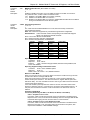
set serial [s0/s1] buffer-time <0/t secs>
This command is related to the ‘set serial s0/s1 buffer-datasize’ command.
The buffering of data shall either wait for datasize configured (in the previous
command) or time t secs.
Example:
Sl
Buffer-datasize
Buffer-time (secs)
Descriptions
1
0 - Default
0 - Default
No buffering. Passes the data to the serial application on the reception of a
character on the serial application.
2
10
0
Buffer till it reaches buffer-datasize (10); then passes it to the serial application.
3
0
10
No buffering. Pass the data to the serial application on the reception of a
character on the serial.
4
10
10
Buffer the characters till it reaches the buffer-datasize (10)
(OR)
wait for the buffer-time (10Secs).
The data is passed on to the serial application depending on which condition is
satisfied first.
Default Value
Success
Error
0 – No buffering
OK
1. Too few arguments
“Usage: set serial s0/s1 buffer-time <0/t secs>
Type ‘set serial s0/s1 buffer-time ?’ for more information”
2. Multiple matches
buffer-datasize
buffer-time
3. Time limit
“error: Time limit supported : <1 – 60 secs>
Type ‘set serial s0/s1 buffer-time ?’ for more information”
Multi-Tech Systems, Inc. MultiConnect Serial-to-Serial Adapter User Guide (S000354A)
33
Chapter 4 – Command Line Interface (CLI)
Serial Commands – Setup
Command Syntax
Description
Default Value
Success
Error
Command Syntax
Description
Default Value
Success
Error
set serial [s0/s1] chat-script <line-num> <expect-string> <send-string>
Sets expect and send strings for the chat script to act on the modem.
Triggers for a reboot upon save.
Important Note: Use double quotes if more than one word is used in the
<expect-string>/<send-string>.
NA
OK
1. Too few arguments
"Usage: set serial s0/s1 chat-script <line-num> <expect-string> <send-string>
Type 'set serial s0/s1 chat-script ?' for more information"
Set serial [s0/s1] connect-type <direct/modem>
Sets the connect type of the serial port to direct/modem connect.
Note: Modem port (S1) will always have connect-type as modem since it is a
built-in modem
Direct
OK
1. Too few arguments
“Usage: set serial s0/s1 connect-type <direct/modem>
Type ‘set serial s0/s1 connect-type ?’ for more information”
2. Invalid string
“error: Invalid string
Type ‘set serial s0/s1 connect-type ?’ for more information”
3. If “set serial s1 connect-type direct” is given
error: modem port s1 is a built-in modem interface; it cannot be set to direct
Command Syntax
Description
Default Value
Success
Error
set serial [s0/s1] connect-state <answering/dialing/both>
Sets the connect state of the serial port to answering/dialing/both state.
Both
OK
1. Too few arguments
“Usage: set serial s0/s1 connect-state <answering/dialing/both>
Type ‘set serial s0/s1 connect-state ?’ for more information”
2. Invalid string
“error: Invalid string
Type ‘set serial s0/s1 connect-state ?’ for more information”
Command Syntax
Description
Default Value
Success
Error
set serial [s0/s1] data-bits <7/8>
Set the data-bits.
8
OK
1. Too few arguments
“Usage: set serial s0/s1 data-bits <7/8>
Type ‘set serial s0/s1 data-bits ?’ for more information”
2. Invalid data-bit setting
“error: Data-bits range supported: [7/8]
Type ‘set serial s0/s1 data-bits ?’ for more information”
Multi-Tech Systems, Inc. MultiConnect Serial-to-Serial Adapter User Guide (S000354A)
34
Chapter 4 – Command Line Interface (CLI)
Serial Commands – Setup
Command Syntax
Description
Default Value
Success
Error
Command Syntax
Description
Default Value
Success
Error
Command Syntax
Description
Default Value
Success
Error
Command Syntax
Description
Default Value
Success
Error
Set serial [s0/s1] flow-control <none/rts-cts>
Set the flow-control of the serial port. By default flow-control is disabled on
the serial port.
rts-cts
OK
1. Too few arguments
“Usage: set serial s0/s1 flow-control <none/rts-cts>
Type ‘set serial s0/s1 flow-control ?’ for more information”
2. Invalid flow-control setting
“error: flow-control supported: [none/rts-cts]
Type ‘set serial s0/s1 flow-control ?’ for more information”
set serial [s0] host-interaction-mode <enable/disable>
This parameter is set by the host to enable the host-interactive-mode.
When this mode is set, the host/serial device can use SMTP client, POP3
client, and HTTP server.
Host interaction mode is valid only for device port S0.
Note: Telnet Auto-Dialout and PPP cannot be enabled when this mode is
enabled.
Disable
OK
1. Too few arguments
"Usage: set serial s0 host-interaction-mode <enable/disable>
Type set serial s0 host-interaction-mode ?”
2. Invalid string
Type set serial s0 host-interaction-mode ?”
3. Port used by Auto-dialout
“ERROR: Port used by Auto-dialout”
4. “set serial s1 host-interaction-mode s1” is given
“error: Command not supported on modem port s1”
set serial [s0/s1] modem connect-string <connect-str>
Sets the Modem Connect string.
Triggers for a reboot upon save.
Note: The configured modem strings takes precedence over the
MODEM.CNF
CONNECT
OK
1. Too few arguments
"Usage: set serial s0/s1 modem connect-string <connect-str>
Type 'set serial s0/s1 modem connect-string ?' for more information"
set serial [s0/s1] modem dial-number <phone-num>
Sets the dial-number to be dialed.
NA
OK
1. Too few arguments
"Usage: set serial s0/s1 modem dial-number <phone-num>
Type 'set serial s0/s1 modem dial-number ?' for more information"
Multi-Tech Systems, Inc. MultiConnect Serial-to-Serial Adapter User Guide (S000354A)
35
Chapter 4 – Command Line Interface (CLI)
Serial Commands – Setup
Command Syntax
Description
Default Value
Success
Error
Command Syntax
Description
Default Value
Success
Error
Command Syntax
Description
Default Value
Success
Error
set serial [s0/s1] modem dial-prefix <dialprefix>
Sets the Modem Dial-Prefix.
Triggers for a reboot upon save.
Note: The configured modem strings takes precedence over the
MODEM.CNF
ATDT
OK
1. Too few arguments
"Usage: set serial s0/s1 modem dial-prefix <dialprefix>
Type 'set serial s0/s1 modem dial-prefix ?' for more information"
Set serial [s0/s1] modem dial-suffix <dialsuffix>
Sets the Modem Dial-suffix. Triggers for a reboot upon save.
Note: The configured modem strings takes precedence over the
MODEM.CNF
^M
OK
1. Too few arguments
"Usage: set serial s0/s1 modem dial-suffix <dialsuffix>
Type 'set serial s0/s1 modem dial-suffix ?' for more information"
Set serial [s0/s1] modem dialing-method <configuration/chat-script>
Sets the modem dialing method.
1. Configuration method: The user shall provide only the dial-number to
reach.
2. Choosing the 'chat' as the dialing-method, the user can write his/her own
script by providing an Expect and a Send sequence.
Refer to: 'set serial s0/s1 chat-script ?' for providing an "Expect" and a
"Send" sequence.
Triggers for a reboot upon save.
Configuration
OK
1. Too few arguments
"Usage: set serial s0/s1 modem dialing-method <configuration/chatscript>
Type 'set serial s0/s1 modem dialing-method ?' for more information"
Multi-Tech Systems, Inc. MultiConnect Serial-to-Serial Adapter User Guide (S000354A)
36
Chapter 4 – Command Line Interface (CLI)
Serial Commands – Setup
Command Syntax
Description
Default Value
Success
Error
Command Syntax
Description
Default Value
Success
Error
Command Syntax
Description
Default Value
Success
Error
set serial [s1] modem dialing-trig-mode <none/dtr/command>
Sets the dialing trigger mode for the modem port S1.
If dialing trig mode is none:
The serial interface will initialize the modem and dial as per the configured
parameters.
If dialing trig mode is dtr:
As soon as a serial device is connected to S0 (DTR goes high), the S1
serial interface will initialize the modem and dial as per the configured
parameters.
If dialing trig mode is command:
The serial interface will dial only on demand. The possible commands that
can trigger the link are:
• "linkup s1" command is issued
• Application trigger (SMTP, POP3 Client, etc)
Note: This command triggers a reboot upon save.
Command
OK
1. Too few arguments
"Usage: set serial s1 modem dialing-trig-mode <none/dtr/command>
Type 'set serial s1 modem dialing-trig-mode ?' for more information"
2. Invalid string
"error: Invalid string
Type 'set serial s1 modem dialing-trig-mode ?' for more information"
set serial s1 modem country-code <value>
Sets the modem country code value to <value>.
This command is valid only for port S1.
OK
1. Too few arguments
“Usage: set serial s1 modem country-code value <value>
Type ‘set serial s1 modem country-code value ?’ for more information”
set serial [s0/s1] modem hangup-string <hangup-str>
Sets the Modem hang-up string.
Triggers for a reboot upon save.
+++ATH0
OK
1. Too few arguments
"Usage: set serial s0/s1 modem hangup-string <hang-str>
Type 'set serial s0/s1 modem hangup-string ?' for more information"
Multi-Tech Systems, Inc. MultiConnect Serial-to-Serial Adapter User Guide (S000354A)
37
Chapter 4 – Command Line Interface (CLI)
Serial Commands – Setup
Command Syntax
Description
Default Value
Success
Error
Command Syntax
Description
Default Value
Success
Error
Command Syntax
Description
Default Value
Success
Error
Command Syntax
Description
Default Value
Success
Error
set serial [s0/s1] modem init-string <init-num> <init-str>
Configures the modem initial strings.
Init-num can range from 1-5.
Triggers for a reboot upon save.
Example: Set serial s0 modem init-string 1 ATZ
Set serial s0 modem init-string 1 "ATZ AT&F"
Important Note:
Use double quotes if more than one word is used in the <init-str>. Refer to
example 2 above. This holds true for all the following commands that need
a string as a parameter.
Init-string 1 is set to 'ATZ'
Init-string 2 is set to ' '
Init-string 3 is set to ' '
Init-string 4 is set to ' '
Init-string 5 is set to ' '
OK
1. Too few arguments
"Usage: set serial s0/s1 modem init-string <init-num> <init-str>
Type 'set serial s0/s1 modem init-string ?' for more information"
Invalid init-num
"ERROR: init-num range supported : [1-5]"
set serial [s0/s1] modem ok-string <ok-str>
Sets the modem OK string.
Triggers for a reboot upon save.
OK
OK
1. Too few arguments
"Usage: set serial s0/s1 modem ok-string <ok-str>
Type 'set serial s0/s1 modem ok-string ?' for more information"
set serial [s0/s1] modem ring-string <ring-str>
Sets the modem ring string. Triggers for a reboot upon save.
RING
OK
1. Too few arguments
"Usage: set serial s0/s1 modem ring-string <ring-str>
Type 'set serial s0/s1 modem ring-string ?' for more information"
set serial [s0/s1] parity <even/odd/none>
Sets parity to even/odd/none.
None
OK
1. Too few arguments
“Usage: set serial s0/s1 parity <even/odd/none>
Type ‘set serial s0/s1 parity ?’ for more information”
2. Invalid parity setting
“error: parity supported: [even/odd/none]
Type ‘set serial s0/s1 parity ?’ for more information”
Multi-Tech Systems, Inc. MultiConnect Serial-to-Serial Adapter User Guide (S000354A)
38
Chapter 4 – Command Line Interface (CLI)
Serial Commands – Setup
Command Syntax
Description
Default Value
Success
Error
Command Syntax
Description
Default Value
Success
Error
Command Syntax
Description
Default Value
Success
Error
set serial [s0] login-string <login-string>
Sets a login-string to the serial port. This command is valid only for port S0.
The Login string can be of length maximum 8 characters.
Upon module boot-up, Login is displayed on the console only if the
characters entered match the login-string configured.
Note: This is applicable only if the "set serial s0 auto-dialin trig-mode" is
char
""
OK
1. Too few arguments
“Usage: set serial s0 login-string <login-string>
Type ‘set serial s0 login-string ? for more information”
2. Invalid string
“ERROR: Invalid string
Type ‘set serial s0 login-string ? for more information”
3. If ‘set serial s1 login-string <login-string>’ is given
“error: Command not supported on modem port s1”
set serial [s0] raw-dialin <enable/disable>
Enables/disables raw mode support for serial auto dial-in on the device port
S0.
Disabled
OK
1. Too few arguments
“Usage: set serial s0 raw-dialin <enable/disable>
Type ‘set serial s0 raw-dialin ? for more information”
2. Multiple matches
raw-dialin
raw-dialout
3. Invalid string
“ERROR: Invalid string
Type ‘set serial s0 raw-dialin ? for more information”
If ‘set serial s1 raw-dialin <enable/disable>’ is given
“error: Command not supported on modem port s1”
set serial [s0] raw-dialout <enable/disable>
Enables/disables raw mode support for auto dialout on the device port S0.
Disabled
OK
1. Too few arguments
“Usage: set serial s0/s1 raw-dialout <enable/disable>
Type ‘set serial s0/s1 raw-dialout ? for more information”
2. Multiple matches
raw-dialin
raw-dialout
3. Invalid string
“error: Invalid string
Type ‘set serial s0/s1 raw-dialout ? for more information”
4. If ‘set serial s1 raw-dialout <enable/disable>’ is given
“error: Command not supported on modem port s1”
Multi-Tech Systems, Inc. MultiConnect Serial-to-Serial Adapter User Guide (S000354A)
39
Chapter 4 – Command Line Interface (CLI)
Serial Commands – Setup
Command Syntax
Description
Default Value
Success
Error
set serial [s0/s1] stop-bits <1/1.5/2>
Sets the stop bits.
1
OK
1. Too few arguments
“Usage: set serial s0/s1 stop-bits <1/1.5/2>
Type ‘set serial s0/s1 stop-bits ?’ for more information”
2. Invalid stop-bit setting
“ERROR: Stop-bit supported : [1, 1.5, 2]
Type ‘set serial s0/s1 stop-bits ?’ for more information”
Serial Commands – Show
Command Syntax
Description
Default Value
Success
Error
Command Syntax
Description
Default Value
Success
Error
Command Syntax
Description
Default Value
Success
Error
show serial [s0/s1] chat-script
Displays the Expect and Send sequence for the serial port S0 or S1.
NA
OK
1. Too few arguments
Possible value(s) are
statistics
modem-configuration
configuration
chat-script
show serial [s0/s1] configuration
Displays serial S0/S1 configuration.
OK
1. Too few arguments
Possible value(s) are
statistics
modem-configuration
configuration
chat-script
show serial [s0/s1] modem-configuration
Displays the modem-related configuration for serial port S0 or S1.
NA
OK
1. Too few arguments
Possible value(s) are
statistics
modem-configuration
configuration
chat-script
Multi-Tech Systems, Inc. MultiConnect Serial-to-Serial Adapter User Guide (S000354A)
40
Chapter 4 – Command Line Interface (CLI)
Serial Commands – Show
Command Syntax
Description
Default Value
Success
Error
Command Syntax
Description
Default Value
Success
Error
show serial [s0/s1] statistics
Displays Serial Statistics.
• Status (If serial is used by any application)
• Rx Bytes
• Rx Errors
• Tx Bytes
• Tx Errors
• Status of EIA signals (CTS, DSR, DCD, RTS, DTR).
Important Note: Serial statistics are only for the current session. Rx
Bytes, Tx Bytes will be reset for every session opened on the serial.
OK
1. Too few arguments
Possible value(s) are
statistics
modem-configuration
configuration
chat-script
show serial modem country code
This command is supported on S1 only.
Displays the supported country codes for this product.
OK
1. Too few arguments
Possible value(s) are
statistics
modem-configuration chat-script
configuration
country-code
Multi-Tech Systems, Inc. MultiConnect Serial-to-Serial Adapter User Guide (S000354A)
41
Chapter 4 – Command Line Interface (CLI)
PPP Commands – Setup
PPP Setup Commands
Note: All PPP Commands use the ppp0 interface, which corresponds to the modem port S1.
Command Syntax
Description
Default Value
Success
Error
set ppp <interface> authentication <enable/disable>
Enables/disables PPP Authentication.
Disabled
OK
1. Too few arguments
Possible argument(s) are disable and enable
2. Invalid string
Invalid argument.
Valid argument(s) are disable and enable
3. Multiple matches: auth-type and authentication
Command Syntax
Description
Default Value
Success
Error
set ppp <interface> auth-type <pap/chap/pap-chap>
Sets the protocol to authenticate the remote peer: PAP/CHAP/PAP-CHAP
PAP
OK
1. Too few arguments
Too few argument(s). Possible argument(s) are:
chap, pap, and pap-chap
2. Invalid authentication type
Invalid argument. Valid argument(s) are
chap, pap, and pap-chap
3. Multiple matches: auth-type and authentication
Command Syntax
Description
Default Value
Success
Error
set ppp <interface> compression <enable/disable>
Enables/disables CCP compression.
Disabled
OK
1. Too few arguments
Possible argument(s) are disable and enable
2. Invalid string
Invalid argument. Valid argument(s) are disable and enable
Command Syntax
Description
set ppp <interface> comp-type <both/bsd/deflate>
Sets the compression type to BSD, DEFLATE or BOTH.
In the case of NON-RAWMODE:
When both is configured as the compression type, the module tries to
negotiate DEFLATE first. In the event of failure, the BSD is negotiated.
In case of RAW-MODE:
Compress-type both is not supported in RAW-MODE, since there are no
negotiations between MultiConnect IP Modules.
Deflate
OK
1. Too few arguments
Too few argument(s). Possible argument(s) are both, bsd, deflate
2. Invalid string
Invalid argument "string"
Valid argument(s) are both, bsd, deflate
Default Value
Success
Error
Multi-Tech Systems, Inc. MultiConnect Serial-to-Serial Adapter User Guide (S000354A)
42
Chapter 4 – Command Line Interface (CLI)
PPP Commands – Setup
Command Syntax
Description
Default Value
Success
Error
Command Syntax
Description
Default Value
Success
Error
Command Syntax
Description
Default Value
Success
Error
Command Syntax
Description
Default Value
Success
Error
set ppp <interface> dialing-max-retries <0-100>
Configures the maximum number of dialing retries.
Maximum dialing retry is 100
5
OK
1. Too few arguments
“Usage: set ppp ppp0 dialing-max-retires [0-100](times)
Type ‘set ppp ppp0 dialing-max-retries ?’ for more information”
2. Multiple matches
dialing-max-retries and dialing-retry-interval
3. Retry range
“error: dialing-max-retries range : [0 - 100]
Type ‘set ppp ppp0 dialing-retry-interval ?’ for more information”
set ppp <interface> dialing-retry-interval <0-300>
Configures the interval for the port to retry dialing.
Maximum dialing retry is 300.
15
OK
1. Too few arguments
“Usage: set ppp ppp0 dialing-retry-interval [0-300](secs)
Type ‘set ppp ppp0 dialing-retry-interval ?’ for more information”
2. Multiple matches
dialing-max-retries and dialing-retry-interval
3. Retry range
“error: dialing-retry-interval range : [0 - 300]
Type ‘set ppp ppp0 dialing-retry-interval ?’ for more information”
set ppp <interface> idle-timeout <0-900>
Configures the dial-on-demand idle timeout value .Maximum dialing retry is
900 secs
600 secs
OK
1. Too few arguments
“Usage: set ppp ppp0 idle-timeout <0-900>
Type set ppp ppp0 idle-timeout ?’ for more information”
2 Idle timeout range
“error: dod-idle-timeout range : [0 - 900]
Type ‘set ppp ppp0 idle-timeout ?’ for more information”
set ppp <interface> ipcp-mode <client-only/client-or-lan>
Sets the IPCP mode-to-client-only or client or LAN.
client-only
OK
1. Too few arguments
Possible argument(s) are client-only and client-or-lan
2. Invalid string
Invalid argument.
Valid argument(s) are client-only and client-or-lan
Multi-Tech Systems, Inc. MultiConnect Serial-to-Serial Adapter User Guide (S000354A)
43
Chapter 4 – Command Line Interface (CLI)
PPP Commands – Setup
Command Syntax
Description
Default Value
Success
Error
set ppp <interface> local-ip-addr <ipaddr> mask <ipmask>
During IPCP negotiations, the configured IP address is sent for the local
interface. In the case where the peer is requested to provide the IP
address, it can be configured as 0.0.0.0
0.0.0.0
255.255.255.0
OK
1. Too few arguments
Possible arguments are IP Address and Mask
2. Invalid IP address/Mask
Invalid argument
Command Syntax
Description
Default Value
Success
Error
set ppp <interface> password <password >
Sets the password that remote peers will use for authentication.
Ipmodule
OK
1. Password Length
Password should have minimum of 8 characters
Command Syntax
Description
set ppp <interface> remote-ip-addr <ipaddr> mask <ipmask>
During IPCP negotiations, this configured IP address is sent for the remote
interface. In the case of the peer being requested to provide the IP address,
it can be configured as 0.0.0.0
0.0.0.0
255.255.255.0
OK
1. Too few arguments
Possible arguments are IP Address and Mask
2. Invalid IP address/Mask
Invalid argument
Default Value
Success
Error
Command Syntax
Description
Default Value
Success
Error
set ppp <interface> username <username>
Sets the user name that the remote peer will use for authentication.
Ipmodule
OK
1. Too few arguments
Possible value(s) are valid user name
Multi-Tech Systems, Inc. MultiConnect Serial-to-Serial Adapter User Guide (S000354A)
44
Chapter 4 – Command Line Interface (CLI)
PPP Commands – Show
Command Syntax
Description
Default Value
Success
Error
Command Syntax
Description
Default Value
Success
Error
Command Syntax
Description
Default Value
Success
Error
show ppp ppp0 configuration
Displays:
PPP Status (enabled/disabled)
Authentication status
Authentication type
Username and password for authentication
Compression status
Compression type
IPCP Mode
Local IP Address
Remote IP Address
NA
OK
1. Too few arguments
Possible argument(s) are
configuration
ip-addr
statistics
link-status
2. Invalid argument
Invalid argument
Valid argument(s) are
configuration
ip-addr
statistics
link-status
show ppp <interface> ip-addr
Displays:
Local IP Address
Remote IP Address
NA
OK
1. Too few arguments
Possible argument(s) are
configuration
ip-addr
statistics
link-status
2. Invalid argument
Invalid argument
Valid argument(s) are
configuration
ip-addr
statistics
link-status
show ppp <interface> link-status
Displays the link status on ppp interface.
OK
Up / Down
1. Too few arguments
Possible argument(s) are
configuration
ip-addr
statistics
link-status
2. Invalid argument
Invalid argument
Valid argument(s) are
configuration
ip-addr
statistics
link-status
Multi-Tech Systems, Inc. MultiConnect Serial-to-Serial Adapter User Guide (S000354A)
45
Chapter 4 – Command Line Interface (CLI)
PPP Commands – Show
Command Syntax
Description
Default Value
Success
Error
show ppp <interface> statistics
Displays PPP Statistics.
OK
1. Too few arguments
Possible argument(s) are
configuration
ip-addr
statistics
link-status
2. Invalid argument
Invalid argument
Valid argument(s) are:
configuration
ip-addr
statistics
link-status
Multi-Tech Systems, Inc. MultiConnect Serial-to-Serial Adapter User Guide (S000354A)
46
Chapter 4 – Command Line Interface (CLI)
HTTP Server Commands – Setup
HTTP Server Commands
The commands in this section are listed in the order in which they might be used.
Command Syntax
Description
Default Value
Success
Error
set ip http-page <default/serial>
This parameter is used by the http server to host the default HTML index or
host-defined http-serial-S0 HTML page.
Default
OK
1. Too few arguments
“Usage: set ip http-page <default/serial>
Type set ip http-page ?”
2. Invalid string
Type "set ip http-page ?”
Command Syntax
Description
Default Value
Success
Error
set ip http <enable/disable>
This enables the http server on the MultiConnect IP to listen on Port 80.
Disable
OK
1. Too few arguments
“Usage: set "ip http <enable/disable>
Type 'set ip http ?' for more information"
2. Invalid string
"ERROR: Invalid string
Type 'set ip http ?' for more information"
Command Syntax
Description
Default Value
Success
Error
set ip http-port <port>
Sets the HTTP server to listen on the specified port.
80
OK
1. Too few arguments
“Usage: set ip http-port <port>
Type set 'ip http-port ?' for more information”
2. Invalid port number
"ERROR: Invalid port number
Type set 'ip http-port ?' for more information”
Command Syntax
set device-parameter P<n> <value>
where n = 0 to 99.
Sets the value of the parameter from the host/serial device.
Value in the default parameter list file uploaded through TFTP.
OK
1. Too few arguments
“Usage: set device P<n> <value>
Type 'set device P<n> ?' for more information”
2. Invalid string
"ERROR: Invalid string
Type 'set device P<n> ?' for more information”
Description
Default Value
Success
Error
Multi-Tech Systems, Inc. MultiConnect Serial-to-Serial Adapter User Guide (S000354A)
47
Chapter 4 – Command Line Interface (CLI)
HTTP Server Commands – Setup
Command Syntax
Description
Default Value
Success
Error
save param
Invoking this command will save the host parameters into the flash. The
“/var/apps” directory is gun zipped to apps.tar.gz and written into flash.
(APPS _SECTOR)
OK
1. Too few arguments
“ERROR: Too few arguments
Type 'save ?' for more information”
HTTP Server Commands – Show
Command Syntax
Description
Default Value
Success
Error
show http configuration
Displays the HTTP related configurations.
OK
1. Too few arguments
“ERROR: Too few arguments
Type 'show http configuration ?' for more information”
Command Syntax
show device-parameter P<n>
where n = 0 to 99.
Displays the value of the requested parameter from MultiConnect IP.
OK
1. Too few arguments
“ERROR: Too few arguments
Type 'show device-parameter ?' for more information”
Description
Default Value
Success
Error
Command Syntax
Description
Default Value
Success
Error
show device-parameter modified
Displays the status of the host parameters; for example, whether they are
changed by the browser.
Returns “Device parameters changed” when values are changed by the
remote browser.
Returns “Device parameters not changed” when values are not changed.
OK
1. Too few arguments
“ERROR: Too few arguments
Type 'show device-parameter ?' for more information”
Multi-Tech Systems, Inc. MultiConnect Serial-to-Serial Adapter User Guide (S000354A)
48
Chapter 4 – Command Line Interface (CLI)
SMTP Client Commands – Setup
SMTP Client Commands
The commands in this section are listed in the order in which they might be used.
Command Syntax
Description
Default Value
Success
Error
set send-mail smtp-server-name <name/ip-address>
Sets the SMTP server name or IP address. Server names must be such
that they can be resolved by the DNS.
NULL
OK
1. Too few arguments
“Usage: set send-mail smtp-server-name <name/ip-address>
Type 'set send-mail smtp-server-name ?' for more information”
2. Invalid name/IP address
“ERROR: Invalid SMTP Server Name/IP Address”
Command Syntax
Description
Default Value
Success
Error
set send-mail smtp-server-port <port>
Sets the SMTP Server port.
25
OK
1. Too few arguments
“Usage: set send-mail smtp-server-port <port>
Type 'set send-mail smtp-server-port ?' for more information”
Command Syntax
Description
Default Value
Success
Error
set send-mail host-name <host name>
Sets the SMTP Client host name.
NULL
OK
1. Too few arguments
“Usage: set send-mail host-name <host name>
Type 'set send-mail host-name ?' for more information”
Command Syntax
Description
Default Value
Success
Error
set send-mail from-address-identity <name>
Sets the ‘From:’ description in the email header as <name>.
NULL
OK
1. Too few arguments
“Usage: set send-mail from-address-identity <name>
Type 'set send-mail from-address-identity ?' for more information”
Command Syntax
Description
Default Value
Success
Error
set send-mail from-address <email-address>
Sets the email-address as the Default From address information.
NULL
OK
1. Too few arguments
“Usage: set send-mail from-address <email-address>
Type 'set send-mail from-address ?' for more information”
Multi-Tech Systems, Inc. MultiConnect Serial-to-Serial Adapter User Guide (S000354A)
49
Chapter 4 – Command Line Interface (CLI)
SMTP Client Commands – Setup
Command Syntax
Description
Default Value
Success
Error
Command Syntax
Description
Default Value
Success
Error
Command Syntax
Description
Default Value
Success
Error
Command Syntax
Description
Default Value
Success
Error
set send-mail to-address <n> <email-address>
where n = 1 to 5.
Sets the email-address as one of the primary addressee. This is the default
email address to which email messages are sent.
NULL
OK
1. Too few arguments
“Usage: set send-mail to-address <n> <email-address>
Type 'set send-mail to-address <n> ?' for more information”
2. Invalid to-address number
“ERROR: to-address numbers supported: [1 to 5]
Type 'set send-mail to-address <n> ?' for more information”
set send-mail cc-address <n> <email-address>
where n = 1 to 5.
Sets the email-address as the alternate addressee (carbon copy). This is
the default email address that the primary addressee's email messages are
copied.
NULL
OK
1. Too few arguments
“Usage: set send-mail cc-address <n> <email-address>
Type 'set send-mail cc-address <n> ?' for more information”
2. Invalid to-address number
“ERROR: cc-address numbers supported: [1 to 5]
Type 'set send-mail cc-address <n> ?' for more information”
set send-mail reply-to-address <email-address>
Sets the email address to be used when the recipient uses the reply-to
button.
NULL
OK
1. Too few arguments
“Usage: set send-mail reply-to-address <email-address>
Type 'set send-mail reply-to-address ?' for more information”
set send-mail subject <data>
Sets the email header subject field to the given data.
NULL
OK
1. Too few arguments
“Usage: set send-mail subject <data>
Type 'set send-mail subject ?' for more information”
Multi-Tech Systems, Inc. MultiConnect Serial-to-Serial Adapter User Guide (S000354A)
50
Chapter 4 – Command Line Interface (CLI)
SMTP Client Commands – Setup
Command Syntax
Description
Default Value
Success
Error
Command Syntax
Description
Default Value
Success
Error
send-mail [-b]
[-t <email-address1, email-address2, ...>]
[-c <email-address1, email-address2, ...>]
[-s <data>]
[-d <msg body>]
Triggers the SMTP Client application. The application enters the interactive
mode or sends the mail according to the command arguments.
Notes:
All the arguments are optional. This implies that an email can be sent by
specifying the parameter(s) in the command line (or) entering them in the
order prompted by MultiConnect IP.
Usage:
-b : binary mode {default is text mode}
-t : To addresses
-c : CC addresses
-s : Subject Data
-d : Message Body
Email Sent Successfully
OK
1. Too few arguments
Usage: send-mail [<-b>] [ -t <email-address, ...>] [-c <email-address,
>] [-s <data>] [-d <msg body>] …
Type 'send-mail ?' for more information”
show send-mail configuration
Displays the SMTP configuration.
OK
1. Too few arguments
“Usage: show send-mail configuration
Type 'show send-mail ?' for more information”
Multi-Tech Systems, Inc. MultiConnect Serial-to-Serial Adapter User Guide (S000354A)
51
Chapter 4 – Command Line Interface (CLI)
POP3 Client Commands – Setup
POP3 Client Commands
Command Syntax
Description
Default Value
Success
Error
Command Syntax
Description
Default Value
Success
Error
set recv-mail server-name <server-name>
This parameter is set by the host to establish the POP3 connection for
receiving the email from the remote server. This also needs DNS to be
enabled on the MultiConnect IP.
None
OK
1. Too few arguments
Usage: set recv-mail server-name <server-name>
Type 'set recv-mail server-name ?' for more information
2. Invalid string
Type 'set recv-mail server-name ?' for more information
set recv-mail server-port <server-port>
This parameter is set by the host to establish the POP3 connection for
receiving email from the remote server.
110
OK
1. Too few arguments
Usage: set recv-mail server-port <server-port>
Type 'set recv-mail server-port ?' for more information
2. Invalid string
Type 'set recv-mail server-port ?' for more information
Command Syntax
Description
Default Value
Success
Error
set recv-mail mailbox-name <mailbox-name>
Sets the mail box user name for POP3 server authentication.
None
OK
1. Too few arguments
Usage: set recv-mail mailbox-name <mailbox-name>
Type 'set recv-mail mailbox-name ?' for more information
2. Invalid string
Type 'set recv-mail mailbox-name ?' for more information
Command Syntax
Description
Default Value
Success
Error
set recv-mail mailbox-password <mailbox-password>
Sets the mail box password for POP3 server authentication.
None
OK
1. Too few arguments
Usage: set recv-mail mailbox-password <mailbox-password>
Type 'set recv-mail mailbox-password ?' for more information
2. Invalid string
Type 'set recv-mail mailbox-password ?' for more information
Multi-Tech Systems, Inc. MultiConnect Serial-to-Serial Adapter User Guide (S000354A)
52
Chapter 4 – Command Line Interface (CLI)
POP3 Client Commands – Setup
Command Syntax
Description
Default Value
Success
Error
Command Syntax
Description
Default Value
Success
Error
Command Syntax
Description
Default Value
Success
Error
Command Syntax
Description
Default Value
Success
Error
Command Syntax
Description
Default Value
Success
Error
set recv-mail leave-on-server <enable/disable>
Set the variable “leave a copy of message on server” flag, which tells the
POP3 server not to delete the emails from it once the emails are received.
Disable
OK
1. Too few arguments
recv-mail list [index]
This command retrieves list of emails from the mailbox.
Displays the list of emails in the order below:
<index of the mail> <size in bytes>
or
Mailbox is empty
OK
1. Too few arguments
Usage: recv-mail list [index]
Type 'recv-mail ?' for more information
recv-mail header [index]
This command receives the header information of all the emails present in
the mailbox if index is not issued. If index is issued, the mail header
corresponding to the index is retrieved.
OK
1. Too few arguments
Usage: recv-mail header [index]
Type 'recv-mail ?' for more information
recv-mail mail [index]
This command retrieves all the pending emails present in the mailbox if
index is not given. If index is issued, the email corresponding to the index is
retrieved.
OK
1. Too few arguments
Usage: recv-mail mail [index]
Type 'recv-mail ?' for more information
recv-mail delete <index>
Deletes the email corresponding to the index. The emails will not be deleted
until the “recv-mail quit” command is executed.
OK
1. Too few arguments
Usage: recv-mail delete <index>
Type 'recv-mail ?' for more information
Multi-Tech Systems, Inc. MultiConnect Serial-to-Serial Adapter User Guide (S000354A)
53
Chapter 4 – Command Line Interface (CLI)
POP3 Client Commands – Setup
Command Syntax
Description
Default Value
Success
Error
recv-mail top <index> <n>
Displays the first <n> lines of the mail corresponding to index.
If n is greater the email size then the whole message is displayed.
OK
1. Too few arguments
Usage: recv-mail top [index]
Type 'recv-mail top' for more information
POP3 Client Commands – Show
Command Syntax
Description
Default Value
Success
Error
recv-mail unique-id-listing [index]
Displays the unique ID listing from the server in the order below: <index of
the mail> <unique id>.
If index is specified, only the corresponding unique ID is displayed.
If index is not specified, all unique IDs in the mail box are displayed.
OK
1. Too few arguments
Usage: recv-mail unique-id-listing [index]
Type 'recv-mail ?' for more information
Command Syntax
Description
Default Value
Success
Error
recv-mail stat [index]
Displays the statistics of an email or emails for a given index.
OK
1. Too few arguments
Usage: recv-mail stat [index]
Type 'recv-mail ?' for more information
Command Syntax
Description
Default Value
Success
Error
show recv-mail configuration
Displays the recv-mail related configuration.
OK
1. Too few arguments
Possible value(s) are configuration
Multi-Tech Systems, Inc. MultiConnect Serial-to-Serial Adapter User Guide (S000354A)
54
Chapter 4 – Command Line Interface (CLI)
FTP Client Commands – Setup
FTP Client Commands
Command Syntax
Description
Default Value
Success
Error
Command Syntax
Description
Default Value
Success
Error
set ftp device <default/ip-address/host-name>
login <username>
[password <password> [account <account password >]
Sets/clears the device login name, password and account password details
that will be used by FTP for automatic authentication.
The Password is an optional parameter and can be configured along with
the machine and login names only
The Account Password is an optional parameter and can be configured
along with device login name and password only.
The IP module prompts for login name and password if these details are
NULL.
Note:
"set ftp machine" resets all these parameters to NULL
NULL
OK
1. Invalid arguments
"error: Login name cannot be null
Type set ftp ? for more information”
2. Invalid arguments
error: Password cannot be null
Type set ftp ? for more information”
3. Invalid arguments
error: Account Password cannot be null
Type set ftp ? for more information”
4. Invalid arguments
error: Invalid usage
Type set ftp ? for more information”
5. Too few arguments
“Usage: set ftp machine <default/ip-address/hostname (1-40)> login
<username (1-20)> [password <password (1-20)>] [account <account
password (1-20)>]
Type set ftp ? for more information”
ftp <Ftp Server-ip-addr>
The FTP client on board connects to the remote FTP server. Upon
successful connection, the Send and Receive commands of the FTP can
be used to perform the required operation.
NA
OK
1. Too few arguments
Possible argument(s) are:
IP-address
2. Invalid IP address
error: invalid ipaddress.
3. When invoked from Command shell connected through TELNET
This command is not supported through Telnet
Multi-Tech Systems, Inc. MultiConnect Serial-to-Serial Adapter User Guide (S000354A)
55
Chapter 4 – Command Line Interface (CLI)
FTP Client Commands – Setup
Command Syntax
Description
Default Value
Success
Error
ftp < [-l] [-t] [-r] > [-p] <ip-address/host-name>
Triggers the FTP client to establish the FTP session with the remote server
and to perform the required action according to the specified option.
-p : Opens the Data connection in Passive mode. (If this option is not given,
the data connection will be opened in Active mode by default).
-l : Requests for the directory and lists the contents of the specified
directory in the server.
-t : Requests for the filename and filesize to the transmitted and reads the
data from the host device and transmits to the server.
-r : Requests for the remote filename to be received. It informs the host
device about the size of the file and retrieves the data from the server when
serial device is ready.
Note:
1. FTP session can be aborted by issuing Ctrl+C at any given time.
NULL
OK
1. Invalid arguments
ftp < [-l] [-t] [-r] > [-p] <ip-address/hostname>
Type set ftp ? for more information”
2. Too few arguments
“Usage: ftp < [-l] [-t] [-r] > [-p] <ip-address/hostname>
Type set ftp ? for more information”
FTP Client Commands – Show
Command Syntax
Description
Default Value
Success
Error
show ftp configuration
Displays the FTP profile configured in the MultiConnect IP.
NULL
OK
1. Too few arguments
Possible value(s) are configured.
Multi-Tech Systems, Inc. MultiConnect Serial-to-Serial Adapter User Guide (S000354A)
56
Chapter 4 – Command Line Interface (CLI)
SNTP Client Commands – Setup
SNTP Client Commands
Command Syntax
Description
Default Value
Success
Error
Command Syntax
Description
Default Value
Success
Error
set sntp client <enable/disable>
Starts the SNTP Client to contact the configured server on UDP port 123
and set the local time.
Disable
OK
1. Too few arguments
“Usage: set sntp-client <enable/disable>
Type set sntp-client ? for more information”
set sntp-client ntp-server-name <ip-address>
Sets the NTP server IP address to which the SNTP Client has to contact to
update the time.
0.0.0.0
OK
1. Invalid arguments
"error: Invalid IP address"
Type set sntp-client ? for more information”
2. Too few arguments
“Usage: set sntp-client ntp-server-name <ip-address>
Type set sntp-client ntp-server-name ? for more information”
Command Syntax
Description
Default Value
Success
Error
set sntp-client time-zone <string (0-3)>
Sets the time zone.
UTC
OK
1. Invalid arguments
"error: Invalid Time Zone"
2. Too few arguments
“Usage: set sntp-client time-zone <string (0-3)>
Type set sntp-client time-zone ? for more information”
Command Syntax
set sntp-client time-zone-offset <+/-hh:mm>
where
hh = 00 to 23
mm = 00 to 59
Sets the offset time from UTC.
+00:00
OK
1. Invalid arguments
"error: Invalid Offset"
2. Too few arguments
“Usage: set sntp-client time-zone-offset <+/-hh:mm>
Type set sntp-client time-zone-offset ? for more information”
Description
Default Value
Success
Error
Multi-Tech Systems, Inc. MultiConnect Serial-to-Serial Adapter User Guide (S000354A)
57
Chapter 4 – Command Line Interface (CLI)
SNTP Client Commands – Setup
Command Syntax
Description
Default Value
Success
Error
set sntp-client polling-time <value>
where
value = 2 to 1440
Sets the polling time at which SNTP client requests the server to update the
time.
300
OK
1. Invalid arguments
"error: Invalid Polling time"
2. Too few arguments
“Usage: set sntp-client polling-time <value>
Type set sntp-client polling-time ? for more information”
Command Syntax
Description
Default Value
Success
Error
set sntp-client daylight-saving <enable/disable>
Enables/Disables the Day Light Saving Mode.
Enable
OK
1. Invalid arguments
"error: Invalid parameter"
2. Too few arguments
“Usage: set sntp-client daylight-saving <enable/disable>
Type set sntp-client daylight-saving ? for more information”
Command Syntax
set sntp-client daylight-saving offset <+/-value>
where
value = 0 to 120 minutes
Sets the offset to use during the Day Light Saving Mode.
60
OK
1. Invalid arguments
"error: Invalid offset value"
2. Too few arguments
“Usage: set sntp-client daylight-saving offset <value>
Type set sntp-client daylight-saving offset ? for more information”
Description
Default Value
Success
Error
Command Syntax
Description
Default Value
Success
Error
set sntp-client daylight-saving start-ordinal <string>
where
string = first/second/third/forth/last
Sets the start ordinal to use during the Day Light Saving Mode.
First
OK
1. Invalid arguments
"error: Invalid start ordinal"
2. Too few arguments
“Usage: set sntp-client daylight-saving start-ordinal <string>
Type set sntp-client daylight-saving start-ordinal ? for more information”
Multi-Tech Systems, Inc. MultiConnect Serial-to-Serial Adapter User Guide (S000354A)
58
Chapter 4 – Command Line Interface (CLI)
SNTP Client Commands – Setup
Command Syntax
Description
Default Value
Success
Error
Command Syntax
Description
Default Value
Success
Error
Command Syntax
Description
Default Value
Success
Error
Command Syntax
Description
Default Value
Success
Error
set sntp-client daylight-saving start-weekday <dayofweek>
where
dayofweek = sunday, monday ... Saturday
Sets the start weekday to use during the Day Light Saving Mode.
Sunday
OK
1. Invalid arguments
"error: Invalid start day of the week"
2. Too few arguments
“Usage: set sntp-client daylight-saving start-weekday <dayofweek>
Type set sntp-client daylight-saving start-weekday ? for more
information”
set sntp-client daylight-saving start-month <month>
where
month = january, february .... December
Sets the start month to use during the Day Light Saving Mode.
April
OK
1. Invalid arguments
"error: Invalid start month"
2. Too few arguments
“Usage: set sntp-client daylight-saving start-month <month>
Type set sntp-client daylight-saving start-month ? for more information”
set sntp-client daylight-saving start-time <hh:mm>
where
hh = 00 to 23
mm = 00 to 59
Sets the start time to use during the Day Light Saving Mode.
02:00
OK
1. Invalid arguments
"error: Invalid start time"
2. Too few arguments
“Usage: set sntp-client daylight-saving start-time <hh:mm>
Type set sntp-client daylight-saving start-time ? for more information”
set sntp-client daylight-saving end-ordinal <string>
where
string = first/second/third/forth/last
Sets the end ordinal to use during the Day Light Saving Mode.
Last
OK
1. Invalid arguments
"error: Invalid end ordinal"
2. Too few arguments
“Usage: set sntp-client daylight-saving end-ordinal <string>
Type set sntp-client daylight-saving end-ordinal ? for more information”
Multi-Tech Systems, Inc. MultiConnect Serial-to-Serial Adapter User Guide (S000354A)
59
Chapter 4 – Command Line Interface (CLI)
SNTP Client Commands – Setup
Command Syntax
Description
Default Value
Success
Error
Command Syntax
Description
Default Value
Success
Error
Command Syntax
Description
Default Value
Success
Error
set sntp-client daylight-saving end-weekday <dayofweek>
where
dayofweek = Sunday, Monday … Saturday
Sets the end weekday to use during the Day Light Saving Mode.
Sunday
OK
2. Invalid arguments
„error: Invalid end day of the week“
2. Too few arguments
“Usage: set sntp-client daylight-saving end-weekday <dayofweek>
Type set sntp-client daylight-saving end-weekday ? for more
information”
set sntp-client daylight-saving end-month <month>
where
month = january, …december
Sets the end month to use during the Day Light Saving Mode.
October
OK
2. Invalid arguments
„error: Invalid end month“
2. Too few arguments
“Usage: set sntp-client daylight-saving end-month <month>
Type set sntp-client daylight-saving end-month ? for more information”
set sntp-client daylight-saving end-time <hh:mm>
where
hh = 00 to 23
mm = 00 to 59
Sets the end time to use during the Day Light Saving Mode.
02:00
OK
2. Invalid arguments
„error: Invalid end time“
2. Too few arguments
“Usage: set sntp-client daylight-saving end-time <hh:mm>
Type set sntp-client daylight-saving end-time ? for more information”
SNTP Client Commands – Show
Command Syntax
Description
Default Value
Success
Error
show sntp configuration
Displays the SNTP configuration
NA
OK
1. Too few arguments
Possible value(s) are configuration
Multi-Tech Systems, Inc. MultiConnect Serial-to-Serial Adapter User Guide (S000354A)
60
Chapter 5 – Setting Country or Region Codes Using the CLI
Chapter 5 – Setting Country or
Region Codes Using the CLI
The Default Country or Region Code is B5.
If You Want to Change the Country or Region Code, Use the Command Line Interface:
Command Syntax
Description
Default Value
Success
Error
set serial s1 modem country-code value <value>
Sets the modem country code value to <value>.
This command is valid only for port S1. Applicable only if the country-code
type is set to code.
OK
1. Too few arguments
“Usage: set serial s1 modem country-code value <value>
Type ‘set serial s1 modem country-code value ?’ for more information”
Notes: There is no validation on the country code value.
To View Country or Region Code:
Command Syntax
Description
Default Value
Success
Error
show serial modem country code
This command is supported on S1 only.
Displays the supported country codes for this product.
OK
1. Too few arguments
Possible value(s) are
statistics
country-code
configuration
chat-script
modem-configuration
Country or Region Codes – The list below is an example of the country or region code settings for the
countries or regions that Multi-Tech currently supports. For your country or region code, please check with MultiTech Technical Support
Country/Region
Argentina
Australia
Austria
Belgium
Brazil
Canada
China
Cyprus
Czech Republic
Denmark
Finland
France
Germany
Greece
Hong Kong
Hungary
Iceland
Indonesia
Ireland
Value (Country Code)
07
09
FD
FD
16
B5
B5
FD
FD
FD
FD
FD
FD
FD
99
FD
FD
99
FD
Country/Region
Italy
Value (Country Code)
FD
Japan
00
Korea
Liechtenstein
B5
FD
Luxembourg
FD
Mexico
Netherlands
New Zealand
B5
FD
7E
Norway
FD
Philippines
Portugal
Slovak Republic
Spain
Sweden
Switzerland
Taiwan
United Kingdom
United States
B5
FD
FD
FD
FD
FD
FE
FD
B5
Multi-Tech Systems, Inc. MultiConnect Serial-to-Serial Adapter User Guide (S000354A)
61
Chapter 6 – Prerequisite Configurations
Chapter 6 – Prerequisite
Configurations
This chapter covers prerequisite tasks, those tasks or configurations that must be completed before you
can set up certain operating scenarios.
Other prerequisite tasks related to specific operating scenarios are described throughout the rest of this
document.
1. MultiConnect IP Communication Interfaces and Conventions
The Serial Interface ports, S0 and S1, correspond to Device Port and Modem Port respectively. This
convention is used throughout this document.
Serial Ports
1. S0 - Device Port - RS-232 port connects to the Host/Serial device.
2. S1 - Modem Port - RJ-11 phone jack port dials the Service Provider, obtains an IP
Address, and provides the IP ability to reach the Host/Serial
devices connected over the device port.
Multi-Tech Systems, Inc. MultiConnect Serial-to-Serial Adapter User Guide (S000354A)
62
Chapter 6 – Prerequisite Configurations
2. MultiConnect IP Modes of Operation
The MultiConnect IP can function in two modes:
•
Transparent Mode
When the MultiConnect IP is configured to function in the modem operation mode, it
functions as a modem. The Host/Serial device connected on the device port can use the
MultiConnect IP as a modem in transparent mode.
Refer to Chapter 9 for application examples that use Transparent Mode.
•
IP Mode
When the MultiConnect IP is configured to function in the IP operation mode, it provides an IP
ability to reach the Hosts/Serial devices connected over the device port. Application such as
SMTP Client, POP3 Client, Telnet Client, Telnet Server, FTP Client, etc. provide this IP ability
to reach the Host/Serial devices.
The figure below depicts the two modes of operation. The modes can be configured through the
Command Line Interface (CLI). By default the MultiConnect IP is set to operate in the IP Mode.
IP Mode
Multi-Tech Systems, Inc. MultiConnect Serial-to-Serial Adapter User Guide (S000354A)
63
Chapter 6 – Prerequisite Configurations
3. Physical Link Established over the Modem Port
For any application such as SMTP Client, HTTP Server, POP3 Client, etc. to function, the PPP link
must be opened up on the modem port.
MultiConnect IP implementation provides three mechanisms for establishing the physical link over the
modem port:
• Dialing-trig-mode NONE
• Dialing-trig-mode DTR
• Dialing-trig-mode Command
Choose the method you desire by configuring the physical link through the Command Line Interface
(CLI). Use the following command to configure the Physical Link Establishment Method:
# set serial [serial-interface] modem dialing-trig-mode
<none/dtr/command>
Note: The modem port is set to modem-answering by default.
The command dialing-trig-mode can be used to set the modem port to dial.
Dialing-trig-mode Functionality
Upon boot-up, the modem starts dialing using the set of configured parameters.
None
Upon boot-up, the modem is set to the answering state by default.
DTR
When the DTR goes high on the device port S0, the modem starts to dial on the
modem port.
Link establishment and link termination is at your discretion.
Command
Command to establish the physical link:
# linkup [serial-interface]
Notes:
• This command is valid only for modem port S1 and is invalid for
device port S0.
• This command can be issued only when the dialing-trig-mode
is command.
Examples:
# linkup s1
ERROR: ‘dialing-trig-mode is not set to command.
# linkup s1
OK: ‘CONNECT 14400 LAPM COMPRESSED’
# linkup s1
ERROR: ‘NO DIALTONE’
# linkup s1
ERROR: ‘NO CARRIER’
# linkup s1
ERROR: ‘NO ANSWER’
Command to terminate the physical link:
# hangup [serial-interface]
Notes:
• This command is valid only for modem port S1 and is invalid for
device port S0
• This command can be issued only when the dialing-trig-mode
is command.
Example:
# hangup s1
OK
This hangs up the physical link
Multi-Tech Systems, Inc. MultiConnect Serial-to-Serial Adapter User Guide (S000354A)
64
Chapter 7 – Telnet Dialout
Chapter 7 – Telnet Dialout
Introduction
Telnet Dialout Feature
The Telnet feature allows you to access the serial port and establish two-way traffic between the
Telnet/RAW-TCP client and the serial device.
This chapter provides examples of a Telnet client on an IP network (over the modem port) connecting
to a remote serial device. The MultiConnect IP acts as a Terminal Server using the Telnet dialout
feature.
Features
The MultiConnect IP, acting as a Terminal Server, accommodates the following features:
• Authenticates the serial port.
• Monitors and waits for activity on the standard Telnet port (23) or user-defined RAW-Socket.
• Opens the serial port from the command prompt (manual dialout) .
• Opens the serial port directly (auto dialout) using a TCP Client according to the configured
port-number.
• Switches between the command prompt and a dial-out session when the session is in Telnet
mode.
Prerequisites
Mandatory Configuration Settings
The following items must be configured in order to use the dial-out feature:
•
Disable the Host Interaction Mode to restrict Telnet-Dial-Out and PPP.
# set serial s0 host-interaction-mode disable
•
Enable Auto dial-out globally on all the serial ports.
# set ip telnet auto-dialout enable
•
Enable Auto dial-out on the serial port S0.
# set serial s0 auto-dialout enable
•
Set the Auto dialout port for the serial port S0.
# set serial s0 auto-dialout-port <port_number>
• Set the Auto dialout protocol for the serial port S0.
# set serial s0 auto-dialout-protocol telnet
An ERROR message displays if any of the above details are not configured or are not valid.
Multi-Tech Systems, Inc. MultiConnect Serial-to-Serial Adapter User Guide (S000354A)
65
Chapter 7 – Telnet Dialout
Optional Configuration Commands
(Return to Scenario 1 - Setup Manual Dialout Notes:)
(Return to Scenario 2 - Auto Dialout Prerequisites)
(Return to Scenario 3 - Auto Dial-out in RAW-Mode Notes:)
The following commands can be used for optional configurations:
•
Enable/Disable the Authentication for Dial-out session
# set login auto-dialout-login <enable/disable>
•
Enable/Disable the Switching-between-Dialout & Command Prompt feature
# set ip telnet escape-monitor <enable/disable>
•
Set the Escape-Monitor-String to switch between Dialout and Command Prompt sessions.
# set ip telnet escape-string "+++inet"
•
Enable/Disable the RAW mode globally for all Dial-out sessions.
# set ip telnet raw-mode <enable/disable>
•
Enable/Disable the RAW mode for the serial port S0.
# set serial s0 raw-dialout <enable/disable>
•
Set the Baud rate for the serial port S0 to be taken for a Dialout session.
# set serial s0 baud-rate <Baud-rate>
•
Set the Flow control for the serial port S0 to be taken for a Dialout session.
# set serial s0 flow-control <rts-cts/none>
•
Set the Parity for the serial port S0 to be taken for a Dialout session.
# set serial s0 parity <even/odd/none>
•
Set the Data bits for the serial port S0 to be taken for a Dialout session.
# set serial s0 data-bits <7/8>
•
Set the Stop bits for the serial port S0 to be taken for a Dialout session.
# set serial s0 stop-bits <1/1.5/2>
•
Set the Flow control for the serial port S1 to be taken for a PPP session
# set serial s1 flow-control <rts-cts/none>
•
Set the Parity for the serial port S1 to be taken for a PPP session
# set serial s1 parity <even/odd/none>
•
Set the Data bits for the serial port S1 to be taken for a PPP session
# set serial s1 data-bits <7/8>
•
Set the Stop bits for the serial port S1 to be taken for a PPP session
# set serial s1 stop-bits <1/1.5/2>
Multi-Tech Systems, Inc. MultiConnect Serial-to-Serial Adapter User Guide (S000354A)
66
Chapter 7 – Telnet Dialout
Scenario 1 – Manual Dialout
Connect to the MultiConnect IP using a Telnet Client on port 23 (configuration port).
At the command prompt, invoke # dialout serial s0. Once the session is opened successfully, there can
be two-way traffic between the Telnet client and the serial device.
•
You can switch from Command Prompt to Dialout session using the restore session command.
•
You can switch from Dialout session to Command Prompt using <escape-monitor-string>.
Manual Dialout Feature Through the Command Shell
Multi-Tech Systems, Inc. MultiConnect Serial-to-Serial Adapter User Guide (S000354A)
67
Chapter 7 – Telnet Dialout
MultiConnect IP Manual Dialout Setup Commands
#
#
#
#
#
set
set
set
set
set
serial
serial
serial
serial
serial
s0
s0
s0
s0
s0
stop-bits 1
baud-rate 115200
data-bits 8
parity none
flow-control rts-cts
#
#
#
#
#
#
#
set
set
set
set
set
set
set
serial
serial
serial
serial
serial
serial
serial
s1
s1
s1
s1
s1
s1
s1
stop-bits 1
baud-rate 115200
data-bits 8
parity none
flow-control rts-cts
connect-type modem
modem dial-number 123
# set serial s1 modem dialing-trig-mode none
(Refer to Chapter 6 - Prerequisite Configurations - Physical Link Established over the Modem
Port for more details)
#
#
#
#
set ppp ppp0 ipcp-mode client-only
set ppp ppp0 username "MultiConnect"
set ppp ppp0 password "MultiConnect"
save
Enable Authentication for PPP Commands
# set ppp ppp0 authentication enable
# set ppp ppp0 authentication-type <pap/chap/pap-chap>
Enable PPP Compression (on both the PPP peers) Commands
# set ppp ppp0 compression enable
# set ppp ppp0 comp-type <both/bsd/deflate>
The Authentication and Compression variations can be used while bringing up the PPP logical
link in all the scenarios (except for Transparent Mode)
Once the physical link is up and PPP interface has acquired an IP address, the MultiConnect IP is
ready to accept a Dial-Out connection.
Use a remote Telnet client and connect to 202.54.39.95 on port 23 (refer to the figure above). On
successful login, at the MultiConnect IP command prompt, invoke
# dial-out serial s0
(The serial port now opens for use.)
Notes:
1. Only one dialout session can be open at a time.
2. The Dialout session is closed when the Telnet session is closed, thereby releasing the serial port.
3. When the Dialout session authentication is enabled as specified in the Optional Configuration
Commands list, the session prompts for the user name and password before opening the session
successfully. (Enabled by default).
4. The serial port is opened with the current serial configuration.
5. When escape-monitor is enabled, care should be taken during file transfer that the escapemonitor-string is not part of the data.
Multi-Tech Systems, Inc. MultiConnect Serial-to-Serial Adapter User Guide (S000354A)
68
Chapter 7 – Telnet Dialout
Scenario 2 – Auto Dialout
In this scenario, the Auto Dialout session in Telnet mode is opened using a Telnet client.
Prerequisites
RAW mode (global and each port) MUST BE DISABLED using the Optional Configuration
Commands.
A Telnet client can open an auto Dialout session by specifying the configured auto-dialout port.
•
Once the session is opened successfully, there can be two-way traffic between the Telnet
session and the remote serial device.
Auto Dialout Feature in Telnet Mode
Multi-Tech Systems, Inc. MultiConnect Serial-to-Serial Adapter User Guide (S000354A)
69
Chapter 7 – Telnet Dialout
MultiConnect IP Auto Dialout in Telnet Mode Setup Commands
# set ip telnet auto-dialout enable
# set serial s0 auto-dialout enable
# set serial s0 auto-dialout-port 5000
# set serial s0 auto-dialout-protocol telnet
#
#
#
#
#
set
set
set
set
set
serial
serial
serial
serial
serial
s0
s0
s0
s0
s0
baud-rate 115200
data-bits 8
parity none
stop-bits 1
flow-control rts-cts
#
#
#
#
#
#
#
set
set
set
set
set
set
set
serial
serial
serial
serial
serial
serial
serial
s1
s1
s1
s1
s1
s1
s1
baud-rate 115200
data-bits 8
parity none
stop-bits 1
flow-control rts-cts
connect-type modem
modem dial-number 123
# set serial s1 modem dialing-trig-mode none
(Refer to Chapter 6 – Prerequisite Configurations - Physical Link Established over the
Modem Port for more details)
#
#
#
#
#
#
#
#
set ppp
set ppp
set ppp
set ppp
set ppp
set ppp
set ppp
save
ppp0
ppp0
ppp0
ppp0
ppp0
ppp0
ppp0
ipcp-mode client-or-lan
authentication enable
auth-type pap
username "MultiConnect"
password "MultiConnect"
local-ip-addr 202.54.39.95 mask 255.255.255.255
remote-ip-addr 202.54.39.96 mask 255.255.255.255
Once the physical link is up and PPP interface has acquired an IP address the
MultiConnect IP is ready to accept an auto-dialout connection.
Use a Telnet client and connect to 202.54.39.95 on port 5000. This eventually establishes a
Telnet auto-dialout session between the MultiConnect IP and the serial device.
Closing the Telnet client closes the serial port in use.
Notes:
1. Only one dialout session to the same port can be opened at one time.
2. When a dialout session authentication is enabled as specified in the optional commands, the session
prompts for a user name and password before opening the session successfully. (Enabled by
default).
3. The serial port is opened with the current serial configuration.
Multi-Tech Systems, Inc. MultiConnect Serial-to-Serial Adapter User Guide (S000354A)
70
Chapter 7 – Telnet Dialout
Scenario 3 – Auto Dialout in RAW Mode
In this scenario, the Auto-Dialout session in RAW mode is opened using a RAW-TCP client.
Prerequisites
RAW mode (Global and each port) MUST BE ENABLED using the Optional Configuration
Commands.
The Auto Dialout session can be opened by a RAW-TCP client by specifying the auto-dialout configured
port. Once the session is opened successfully, there can be two-way traffic between the Telnet session
and the remote serial device.
Important
You cannot switch between the Command Prompt and the Dialout session in RAW-mode.
Auto Dialout Feature in RAW Mode
Multi-Tech Systems, Inc. MultiConnect Serial-to-Serial Adapter User Guide (S000354A)
71
Chapter 7 – Telnet Dialout
Commands to Setup Auto Dial-out in RAW-Mode for MultiConnect IP
# set ip telnet auto-dialout enable
# set ip telnet raw-mode enable
#
#
#
#
#
set
set
set
set
set
serial
serial
serial
serial
serial
s0
s0
s0
s0
s0
stop-bits 1
baud-rate 115200
data-bits 8
parity none
flow-control rts-cts
#
#
#
#
set
set
set
set
serial
serial
serial
serial
s0
s0
s0
s0
auto-dialout enable
raw-dialout enable
auto-dialout-port 5000
auto-dialout-protocol telnet
#
#
#
#
#
#
#
set
set
set
set
set
set
set
serial
serial
serial
serial
serial
serial
serial
s1
s1
s1
s1
s1
s1
s1
stop-bits 1
baud-rate 115200
data-bits 8
parity none
flow-control rts-cts
connect-type modem
modem dial-number 123
# set serial s1 modem dialing-trig-mode none
(Refer to Chapter 6 – Prerequisite Configurations - Physical Link Established over the Modem
Port for more details)
#
#
#
#
set ppp ppp0 ipcp-mode client-only
set ppp ppp0 username "MultiConnect"
set ppp ppp0 password "MultiConnect"
save
Once the physical link is up and PPP interface has acquired an IP address the
MultiConnect IP is ready to accept Auto dialout connection.
Use a Telnet client and connect to 202.54.39.95 on port 5000 (RAW TCP socket). This eventually
establishes a Telnet auto-dial-out session (In RAWMODE) with the MultiConnect IP, thereby
opening the serial port for use.
Closing the Telnet client closes the serial port in use.
Notes:
1. You cannot open more than one dialout session to the same port.
2. When the Dialout session authentication is enabled as specified in the Optional Configuration
Commands, the session prompts for a user name and password before opening the session
successfully.
3. The serial port is opened with the current serial configuration.
Multi-Tech Systems, Inc. MultiConnect Serial-to-Serial Adapter User Guide (S000354A)
72
Chapter 8 – Auto Dial-in Feature
Chapter 8 – Auto Dial-in Feature
Introduction
The auto dial-in feature enables the MultiConnect IP to act as a Telnet client thus facilitating the serial
device to access any Telnet/terminal servers on the IP network (over the built-in modem interface). Once
the session (Serial Client to Server) is opened successfully, it allows two-way traffic between the serial
device and the remote server.
The MultiConnect IP, acting as a Telnet/RAW-TCP client, accommodates the following features when
configured:
• Support to open the session using Telnet client (residing in the MultiConnect IP) in Telnet Mode or
RAW Mode.
• Support to open the session to the specified port from a Serial Command prompt (Manual Dial-in).
• Switching between a Command prompt and a Dial-in session when the session is in Telnet mode.
• Support to open the session to the configured port directly (Serial Auto Dial-in) whenever the serial
port is free.
Prerequisites
Mandatory Configuration Settings
The following items must be configured in order to use the dial-in feature:
• Enable Auto dial-in globally on all the serial ports.
# set serial auto-telnet enable
• Enable Auto dial-in on the serial port S0.
# set serial s0 auto-dial-in enable
• Set the Auto dial-in protocol.
# set serial s0 auto-dialin-protocol telnet
• Set the Auto dial-in Server IP Address.
# set serial s0 auto-dialin-ipaddress <ipaddress>
• Set the port to the one, which the Telnet client will be connected.
# set serial s0 auto-dialin-port <port_number>
An ERROR message will display if any of the above details are not configured or not valid.
Optional Configuration Settings
The following commands can be used for optional configurations:
•
•
•
•
•
Enable/Disable Switching-between-Dial-in and the Command Prompt feature.
# set serial escape-monitor <enable/disable>
Set the Escape-Monitor-String to switch between Dial-in and Command Prompt sessions.
# set serial escape-string "+++inet"
Set the Serial Dial-in Trigger mode. It dictates the criterion for establishing a connection.
The options provided are on reception of <char/ dtr/ dtr-char/ none>.
Refer to the command line configuration section for details about this command.
# set serial s0 auto-dialin trig-mode <char/dtr/dtr-char/none>
Enable/Disable the RAW mode globally for all Auto-Dial-in sessions.
# set ip telnet raw-mode <enable/disable>
Enable/Disable the RAW mode for Auto-Dial-in session on serial port S0.
# set serial s0 raw-dial-in <enable/disable>
Multi-Tech Systems, Inc. MultiConnect Serial-to-Serial Adapter User Guide (S000354A)
73
Chapter 8 – Auto Dial-in Feature
Scenario 1 – Manual Serial Dial-in
Login to the Command prchat-scriptompt from the serial side.
Invoke # telnet <ip-address> <port> at the command prompt. Once the session is opened
successfully, there can be two-way traffic between the serial device and the remote server.
•
You can switch from Command Prompt to Dial-in session using the restore session command.
•
You can switch from Dial-in session to Command Prompt using <escape-monitor-string>.
Manual Dial-in Feature through the Command Shell
Multi-Tech Systems, Inc. MultiConnect Serial-to-Serial Adapter User Guide (S000354A)
74
Chapter 8 – Auto Dial-in Feature
MultiConnect IP Manual Dial-In Setup Commands
#
#
#
#
#
set
set
set
set
set
serial
serial
serial
serial
serial
s0
s0
s0
s0
s0
baud-rate 115200
data-bits 8
parity none
stop-bits 1
flow-control rts-cts
#
#
#
#
#
#
#
set
set
set
set
set
set
set
serial
serial
serial
serial
serial
serial
serial
s1
s1
s1
s1
s1
s1
s1
baud-rate 115200
data-bits 8
parity none
stop-bits 1
flow-control rts-cts
connect-type modem
modem dial-number 123
# set serial s1 modem dialing-trig-mode none
(Refer to the Chapter 6 Prerequisite Configurations - Physical Link Established over the
Modem Port for more details)
#
#
#
#
#
#
#
#
set ppp
set ppp
set ppp
set ppp
set ppp
set ppp
set ppp
save
ppp0
ppp0
ppp0
ppp0
ppp0
ppp0
ppp0
ipcp-mode client-or-lan
authentication enable
auth-type pap
username "MultiConnect"
password "MultiConnect"
local-ip-addr 202.54.39.95 mask 255.255.255.255
remote-ip-addr 202.54.39.96 mask 255.255.255.255
Once the physical link is up and the PPP interface has acquired an IP address, the
MultiConnect IP is ready to use.
Login to the module through the serial port. At the command shell invoke:
# telnet 202.54.39.96 23
The Telnet client on board in the MultiConnect IP establishes a virtual serial tunnel between
the serial device and the Telnet Server.
Notes:
•
You cannot open more than one dial-in session.
•
The dial-in session is closed when the Telnet session is closed.
•
When escape-monitor is enabled, care should be taken during file transfer that the escapemonitor-string is not part of the data.
Multi-Tech Systems, Inc. MultiConnect Serial-to-Serial Adapter User Guide (S000354A)
75
Chapter 8 – Auto Dial-in Feature
Scenario 2 – Serial Auto Dial-in in Telnet Mode
This example shows how to setup a serial auto dial-in session in Telnet mode. The auto dial-in session is
opened by Telnet client embedded in the MultiConnect IP to the configured server on a configured port.
Once the session is opened successfully, there can be two-way traffic between the serial device and the
remote server.
•
You can switch from Command Prompt to Dial-in session using the restore session command.
•
You can switch from Dial-in session to Command Prompt using <escape-monitor-string>.
Prerequisites
•
RAW mode (Global and each port) MUST BE DISABLED using the following command:
Enable/Disable the RAW mode globally for all Auto-Dial-in sessions:
# set ip telnet raw-mode <enable/disable>
Auto Dial-in Feature in Telnet Mode
Multi-Tech Systems, Inc. MultiConnect Serial-to-Serial Adapter User Guide (S000354A)
76
Chapter 8 – Auto Dial-in Feature
MultiConnect IP Auto Dial-In Setup in Telnet Mode Commands
#
#
#
#
#
#
set
set
set
set
set
set
serial
serial
serial
serial
serial
serial
auto-telnet enable
s0 auto-dialin enable
s0 auto-dialin trig-mode dtr-char
s0 auto-dialin-ipaddress 202.54.39.96
s0 auto-dialin-port 5000
s0 auto-dialin-protocol telnet
#
#
#
#
#
set
set
set
set
set
serial
serial
serial
serial
serial
s0
s0
s0
s0
s0
stop-bits 1
baud-rate 115200
data-bits 8
parity none
flow-control rts-cts
#
#
#
#
#
#
#
set
set
set
set
set
set
set
serial
serial
serial
serial
serial
serial
serial
s1
s1
s1
s1
s1
s1
s1
stop-bits 1
baud-rate 115200
data-bits 8
parity none
flow-control rts-cts
connect-type modem
modem dial-number 123
# set serial s1 modem dialing-trig-mode none
(Refer to the Chapter 6 Prerequisite Configurations - Physical Link Established over the Modem
Port for more details)
#
#
#
#
set ppp ppp0 ipcp-mode client-only
set ppp ppp0 username "MultiConnect"
set ppp ppp0 password "MultiConnect"
save
Once the PPP link is up with an IP address, the auto dial-in session can be probed. When
detecting either a DTR signal or when any character is received from the serial device connected
to the RS-232 serial port of MultiConnect IP, the Telnet client on board in the MultiConnect IP
establishes a Telnet session to 202.54.39.96 on port 23.
The serial tunnel between the serial device and the Telnet Server terminates in one of the
following conditions.
•
The connection is broken between the serial device and the serial port of the
MultiConnect IP.
•
The Telnet Client on board is terminated.
•
The Telnet Server terminates the session.
Notes:
1. You cannot open more than one Dial-in session.
2. The Dial-in session is closed when the configuration session is closed (if opened).
3. When escape-monitor is enabled, care should be taken during file transfer that the escapemonitor-string is not part of the data.
Multi-Tech Systems, Inc. MultiConnect Serial-to-Serial Adapter User Guide (S000354A)
77
Chapter 8 – Auto Dial-in Feature
Scenario 3 – Auto Dial-in Session in RAW Mode
This scenario shows how to configure an auto dial-in session in RAW mode. The auto dial-in session is
opened by Telnet client (embedded in the MultiConnect IP) in RAW-mode to the configured server on a
configured port number. Once the PPP link is up with an IP address, the auto dial-in session can be
probed as in the Auto Dial-In scenario below.
Prerequisites
RAW mode (Global and each port) MUST BE ENABLED using the following command:
Enable/Disable the RAW mode globally for all Auto-Dial-in sessions:
# set ip telnet raw-mode <enable/disable>
Important – You cannot switch between the Command Prompt and a Dial-in session in RAWmode. Also, you cannot open more than one Dial-in session.
Auto Dial-in Feature in RAW Mode
MultiConnect IP Auto Dial-In in RAW Mode Setup Commands
# set ip telnet raw-mode enable
#
#
#
#
#
#
#
set
set
set
set
set
set
set
serial
serial
serial
serial
serial
serial
serial
auto-telnet enable
s0 auto-dialin enable
s0 raw-dialin enable
s0 auto-dialin trig-mode dtr-char
s0 auto-dialin-ipaddress 202.54.39.96
s0 auto-dialin-port 5000
s0 auto-dialin-protocol telnet
#
#
#
#
#
set
set
set
set
set
serial
serial
serial
serial
serial
s0
s0
s0
s0
s0
stop-bits 1
baud-rate 115200
data-bits 8
parity none
flow-control rts-cts
#
#
#
#
#
#
#
set
set
set
set
set
set
set
serial
serial
serial
serial
serial
serial
serial
s1
s1
s1
s1
s1
s1
s1
stop-bits 1
baud-rate 115200
data-bits 8
parity none
flow-control rts-cts
connect-type modem
modem dial-number 123
# set serial s1 modem dialing-trig-mode none
(Refer to Chapter 6 - Prerequisite Configurations - Physical Link Established over the Modem Port)
#
#
#
#
set ppp ppp0 ipcp-mode client-only
set ppp ppp0 username "MultiConnect"
set ppp ppp0 password "MultiConnect"
save
Multi-Tech Systems, Inc. MultiConnect Serial-to-Serial Adapter User Guide (S000354A)
78
Chapter 8 – Auto Dial-in Feature
Scenario 4 – Serial Tunneling Mode
The scenario shows a serial tunnel established between two serial devices (Serial Device-1, Serial
Device-2) using two MultiConnect IP modules, which are located apart geographically. Once the PPP link
is up with an IP address on S1, the dial-in session can occur.
The Serial Devices then communicate to each other across the MultiConnect IP modules.
Serial Tunneling
Multi-Tech Systems, Inc. MultiConnect Serial-to-Serial Adapter User Guide (S000354A)
79
Chapter 8 – Auto Dial-in Feature
Commands for Serial Tunneling Setup Using Two MultiConnect IP Modules
Commands for MultiConnect IP Module 1 (Configure for Serial Auto Dial-in)
# set ip telnet raw-mode enable
# set serial auto-telnet enable
# set serial s0 auto-dialin enable
# set serial s0 raw-dialin enable
# set serial s0 auto-dialin trig-mode dtr-char
# set serial s0 auto-dialin-ipaddress 202.54.39.96
# set serial s0 auto-dialin-port 5000
# set serial s0 auto-dialin-protocol telnet
# set serial s0 stop-bits 1
# set serial s0 baud-rate 115200
# set serial s0 data-bits 8
# set serial s0 parity none
# set serial s0 flow-control rts-cts
# set serial s1 stop-bits 1
# set serial s1 baud-rate 115200
# set serial s1 data-bits 8
# set serial s1 parity none
# set serial s1 flow-control rts-cts
# set serial s1 connect-type modem
# set serial s1 modem dial-number 123
# set serial s1 modem dialing-trig-mode none
(Refer to Chapter 6 – Prerequisite Configurations - Physical Link Established over the Modem Port)
# set ppp ppp0 enable
# set ppp ppp0 ipcp-mode client-or-lan
# set ppp ppp0 authentication enable
# set ppp ppp0 auth-type pap
# set ppp ppp0 username "MultiConnect"
# set ppp ppp0 password "MultiConnect"
# set ppp ppp0 local-ip-addr 202.54.39.95 mask 255.255.255.255
# set ppp ppp0 remote-ip-addr 202.54.39.96 mask 255.255.255.255
# save
Commands for MultiConnect IP Module 2 (Configure for Telnet Auto Dial-out)
# set ip telnet auto-dialout enable
# set ip telnet raw-mode enable
# set serial s0 auto-dialout enable
# set serial s0 auto-dialout-port 5000
# set serial s0 auto-dialout-protocol telnet
# set serial s0 raw-dialout enable
# set serial s0 baud-rate 115200
# set serial s0 data-bits 8
# set serial s0 parity none
# set serial s0 stop-bits 1
# set serial s0 flow-control rts-cts
# set serial s1 baud-rate 115200
# set serial s1 data-bits 8
# set serial s1 parity none
# set serial s1 stop-bits 1
# set serial s1 flow-control rts-cts
# set serial s1 connect-type modem
# set serial s1 modem dialing-trig-mode command
(The default mode is answering. This command changes the mode to answering.)
#
#
#
#
#
#
#
#
#
set ppp
set ppp
set ppp
set ppp
set ppp
set ppp
set ppp
set ppp
save
ppp0
ppp0
ppp0
ppp0
ppp0
ppp0
ppp0
ppp0
enable
ipcp-mode client-or-lan
authentication enable
auth-type pap
username "MultiConnect"
password "MultiConnect"
local-ip-addr 202.54.39.96 mask 255.255.255.255
remote-ip-addr 202.54.39.95 mask 255.255.255.255
Multi-Tech Systems, Inc. MultiConnect Serial-to-Serial Adapter User Guide (S000354A)
80
Chapter 9 – Modem (Transparent) Mode
Chapter 9 – Modem (Transparent)
Mode
Introduction
In the modem mode (also called transparent mode), raw data is communicated between serial ports 1
and 2. This means that:
• Data received on serial port S0 is transmitted on serial port S1
• Data received on serial port S1 is transmitted on serial port S0
Transparent mode can be used in the following applications:
• The MultiConnect IP is used as a Modem
• Serial Tunneling
Prerequisites
•
Transparent Mode must be enabled
# set operation-mode modem
•
Host Interaction mode must be disabled
# set serial s0 host-interaction-mode disable
•
Enable Switching-between Data mode and Command mode
# set serial s0 escape-monitor enable
•
Set the Escape-Monitor-String to switch between Data mode and Command mode
# set serial s0 escape-string "+++inets0"
Multi-Tech Systems, Inc. MultiConnect Serial-to-Serial Adapter User Guide (S000354A)
81
Chapter 9 – Modem (Transparent) Mode
Scenario 1 – MultiConnect IP as a Modem
In this scenario, once the physical link is up on the built-in modem interface; i.e., by dialing or answering,
the serial device connected to the RS-232 interface (S0 of the target) can communicate to the device on
the built-in modem interface (S1 of the target) and vice-versa.
MultiConnect IP as a Modem
Commands for MultiConnect IP as a Modem
# set operation-mode modem
# set serial s0 escape-monitor enable
# set serial s0 escape-string "+++inets0"
#
#
#
#
#
set
set
set
set
set
serial
serial
serial
serial
serial
s0
s0
s0
s0
s0
stop-bits 1
baud-rate 115200
data-bits 8
parity none
flow-control rts-cts
#
#
#
#
#
#
set serial
set serial
set serial
set serial
set serial
save
s1
s1
s1
s1
s1
stop-bits 1
baud-rate 115200
data-bits 8
parity none
flow-control rts-cts
Notes:
•
•
•
You can switch from Data mode to Command mode using the escape-monitor-string
configuration. The control is transferred to the command prompt. Either “Login” or the
command shell is prompted depending on the configuration.
You can switch from Command mode to Data mode using the restore session command.
The data session is dropped if the physical link goes down.
Multi-Tech Systems, Inc. MultiConnect Serial-to-Serial Adapter User Guide (S000354A)
82
Chapter 9 – Modem (Transparent) Mode
Scenario 2 – Serial Tunneling in Transparent
Mode
In this scenario, two MultiConnect IP modules in transparent mode aid in the communication between two
serial devices that are connected to the RS-232 interface (S0) of the MultiConnect IP modules. Serial
tunneling is achieved in the transparent mode where raw data is communicated.
Serial Tunneling in Transparent Mode
Multi-Tech Systems, Inc. MultiConnect Serial-to-Serial Adapter User Guide (S000354A)
83
Chapter 9 – Modem (Transparent) Mode
Commands for MultiConnect IP - 1 (Dialing End)
# set operation-mode modem
# set serial s0 escape-monitor enable
# set serial s0 escape-string "+++inets0"
#
#
#
#
#
set
set
set
set
set
serial
serial
serial
serial
serial
s0
s0
s0
s0
s0
stop-bits 1
baud-rate 115200
data-bits 8
parity none
flow-control rts-cts
#
#
#
#
#
#
set serial
set serial
set serial
set serial
set serial
save
s1
s1
s1
s1
s1
stop-bits 1
baud-rate 115200
data-bits 8
parity none
flow-control rts-cts
Commands for MultiConnect IP - 2 (Answering End)
# set operation-mode modem
# set serial s0 escape-monitor enable
# set serial s0 escape-string "+++inets0"
#
#
#
#
#
set
set
set
set
set
serial
serial
serial
serial
serial
s0
s0
s0
s0
s0
baud-rate 115200
data-bits 8
parity none
stop-bits 1
flow-control rts-cts
#
#
#
#
#
#
set serial
set serial
set serial
set serial
set serial
save
s1
s1
s1
s1
s1
baud-rate 115200
data-bits 8
parity none
stop-bits 1
flow-control rts-cts
Steps for Establishing a Physical Link in Transparent Mode
1. Complete the configuration listed above.
2. At the dialing end, invoke the following commands:
atz
at&f
atdt <dial no>
3. Once the physical connection is up, the data channel between the two MultiConnect IP
modules is established.
Note: Only raw data is forwarded between the MultiConnect IP modules, and no data
integrity check is provided.
4. Type +++ followed by ATH0 to hangup the modem.
Notes
• You can switch from Data mode to Command mode using the escape-monitor-string
command. The Command mode transfers control to the Command Shell of MultiConnect IP.
• You can switch from Command mode to Data mode using the restore session command.
• The data session is dropped if the physical link goes down.
Multi-Tech Systems, Inc. MultiConnect Serial-to-Serial Adapter User Guide (S000354A)
84
Chapter 10 − Modem Mode AT Commands, S-Registers, and Result Codes
Chapter 10 – Modem Mode AT
Commands, S-Registers, Result Codes
This chapter covers the V.22bis, V.32, V.34, and V.92 commands, S-Registers, and Result Codes. The
AT commands are used to control the operation of your modem. They are called AT commands because
the characters AT must precede each command to get the ATtention of the modem.
AT commands can be issued only when the modem is in command mode or online command mode. The
modem is in command mode whenever it is not connected to another modem. The modem is in data
mode whenever it is connected to another modem and ready to exchange data. Online command mode is
a temporary state in which you can issue commands to the modem while connected to another modem.
To put the modem into online command mode from data mode, you must issue an escape sequence
(+++) followed immediately by the AT characters and the command, e.g., +++ to hang up the modem. To
return to data mode from online command mode, you must issue the command ATO.
To send AT commands to the modem you must use a communications program, such as the
HyperTerminal applet in Windows, or some other available terminal program. You can issue commands
to the modem either directly, by typing them in the terminal window of the communications program, or
indirectly, by configuring the operating system or communications program to send the commands
automatically. Fortunately, communications programs make daily operation of modems effortless by
hiding the commands from the user. Most users, therefore, need to use AT commands only when
reconfiguring the modem, e.g., to turn autoanswer on or off.
The format for entering an AT command is ATXn, where X is the command and n is the specific value for
the command, sometimes called the command parameter. The value is always a number. If the value is
zero, you can omit it from the command; thus, AT&B is equivalent to AT&B0. Most commands have a
default value, which is the value that is set at the factory.
You must press ENTER (depending on the terminal program it could be some other key) to send the
command to the modem. Any time the modem receives a command, it sends a response known as a
result code. The most common result codes are OK, ERROR, and the CONNECT messages that the
modem sends to the computer when it is connecting to another modem. For a table of valid result codes,
see “Result Codes” at the end of this chapter.
You can issue several commands in one line, in what is called a command string. The command string
begins with AT and ends when you press ENTER. Spaces to separate the commands are optional; the
command interpreter ignores them. The most familiar command string is the initialization string, which is
used to configure the modem when it is turned on or reset, or when your communications software calls
another modem.
Escape Code Sequence +++
When the modem has established a connection and has entered online data mode, it is possible to break
into the data transmission in order to issue further commands to the modem in an online command mode.
This is achieved by the DTE sending to the modem a sequence of three ASCII characters specified by SRegister S2. The default character is '+'. The maximum time allowed between receipt of the last character
of the three-escape character sequence (+++) from the DTE and sending of the OK result code to the
DTE is controlled by the S12 register.
Command Organization
The commands in this chapter are listed in the following order:
• First, the commands that begin with letters are listed in alphabetical order
• Then the commands that begin with symbols are listed in this order &, \, –, %, +, #, +++
• Fast Connect Commands
• V.92 Commands
Multi-Tech Systems, Inc. MultiConnect Serial-to-Serial Adapter User Guide (S000354A)
85
Chapter 10 − Modem Mode AT Commands, S-Registers, and Result Codes
Command Types
The following list should help if you are looking for a particular type of command. This list categorizes AT
Commands by function.
Generic Modem Control Commands
Z
+VCID
+VRID
\N
I
+GMI
+GMM
+GMR
+GCAP
+GCI
&F
&T
&Y
&W
&Zn=x
Soft Reset and Restore Profile
Caller ID
Report Retrieved Caller ID
Operating Mode – Error Control
Identification
Request Manufacturer Identification
Request Model Identification
Request Revision Identification
Request Complete Capabilities List
Country of Installation
Restore Factory Configuration (Profile)
Local Analog Loopback Test
Designate a Default Profile
Store Current Configuration
Store Telephone Number
DTE–Modem Interface Commands
E
Q
V
W
X
&C
&D
&K
&R
&S
+IPR
+IFC
+ILRR
Command Echo
Quiet Result Code Control
Result Code Form
Connect Message Control
Extended Result Codes
RLSD (DCD) Option
Data Terminal Ready (DTR) Option
Flow Control
RTS/CTS Option
DSR Override
Fixed DTE Rate
DTE-Modem Local Flow Control
DTE-Modem Local Rate Reporting
Call Control Commands
D
T
P
A
H
O
L
M
&G
&P
&V
&V1
\V
%L
%Q
-STE
Dial
Set Tone Dial Default
Set Pulse Dial Default
Answer
Disconnect (Hang-up)
Return to Online Data Mode
Speaker Volume
Speaker Control
Select Guard Tone
Select Pulse Dial Make/Break Ratio
Display Current Configuration and Stored Profiles
Display Last Connection Statistics
Single Line Connect Message Enable
Report Line Signal Level
Report Line Signal Quality
Set Telephony Extension
Multi-Tech Systems, Inc. MultiConnect Serial-to-Serial Adapter User Guide (S000354A)
86
Chapter 10 − Modem Mode AT Commands, S-Registers, and Result Codes
Call Control Commands
+MS
+MR
%E
%U
B
Modulation Selection
Modulation Reporting Control
Enable/Disable Line Quality Monitor and Auto-Retrain
Select µ-Law or A-Law Codec Type
Communication Standard – CCITT or Bell
Error Control Commands
+ES
+EB
+ESR
+EFCS
+ER
+ER <type>
+ETBM
\B
\K
-K
Error Control
Break Handling in Error Control Operation
Selective Repeat
32-bit Frame Check Sequence
Error Control Reporting
Report the Current Error Control
Call Termination Buffer Management
Transmit Break to Remote
Break Control
MNP Extended Services
Data Compression Commands
+DS
+DR
%C
Data Compression
Data Compression Reporting
Enable/Disable Data Compression
V.8/V.8bis Commands
+A8E
+A8I
V.8 and V.8bis Operation Controls
CI Signal Indication
Diagnostic Commands
#U
Last Call Status Report
FastConnect Commands
$F
FastConnect Control
V.92 +P and -Q Commands
+PCW
+PMH
+PMHR
+PMHT
+PIG
+PMHF
+PQC
+PSS
-QCPC
-QCPS
Call Waiting Enable
Modem-on-Hold Enable
Initiate Modem-on-Hold
Modem-on-Hold Timer
PCM Upstream Ignore
V.92 Modem-on-Hold Hook Flash
V.92 Phase 1 and Phase 2 Control
Use Short Sequence
Force Full Startup Procedure on Next Connection
Enable Quick Connect Profile Save
Multi-Tech Systems, Inc. MultiConnect Serial-to-Serial Adapter User Guide (S000354A)
87
Chapter 10 − Modem Mode AT Commands, S-Registers, and Result Codes
Command Detail
Command:
Values:
Description:
AT
Command:
Values:
Description:
Command:
Values:
Attention Code
n/a
The attention code precedes all command lines except for escape sequences.
ENTER Key
n/a
Press the ENTER (RETURN) key to execute most commands.
A
Description:
Answer
n/a
Answer call before final ring. The modem will go off-hook and attempt to answer an
incoming call if correct conditions are met. Upon successful completion of answer
handshake, the modem will go on-line in answer mode. This command may be
affected by the state of Line Current Sense, if enabled. (Most countries do not
require Line Current Sense.) Operation is also dependent upon country-specific
requirements.
The modem will enter the connect state after exchanging carrier with the remote
modem.
If no carrier is detected within a period specified in register S7, the modem hangs
up.
Any character entered during the connect sequence will abort the connection
attempt.
Command:
Values:
Description:
A/
Repeat Last Command
n/a
Repeats the last command string. Do not precede this command with AT. Do not press
Enter to execute.
Command:
Values:
Default:
Description:
Bn
Communication Standard Setting – ITU-T or Bell
n = 0, 1
0
When the modem is configured to allow either option, the modem will select Bell or ITU-T
modulation for a line speed connection of 300 or 1200 bps. Any other line speed will use an
ITU-T modulation standard. The parameter value, if valid, is written to S27 bit 6.
B0 Selects ITU-T operation at 300 or 1200 bps during Call Establishment and a
subsequent connection.
B1 Selects Bell operation at 300 or 1200 bps during Call Establishment and a subsequent
connection.
B2 Selects V.23 half-duplex operation at 1200 bps during Call Establishment and a
subsequent connection. (V.22bis only).
B3 Disables V.23 half-duplex operation. (V.22bis only).
Command:
Values:
Default:
Description:
Ds
Dial
s = dial string (phone number and dial modifiers)
none
This command directs the modem to go on-line, dial according to the string entered and
attempt to establish a connection. If no dial string is supplied, the modem will go on-line and
attempt the handshake in originate mode.
Note: If the ATD command is issued before the S1 register has cleared, the modem will
respond with the NO CARRIER result code.
Dial Modifiers
0-9 DTMF digits 0 to 9.
*
The 'star' digit (tone dialing only).
#
The 'gate' digit (tone dialing only).
A-D Some countries may prohibit sending of these digits during dialing (tone dialing
only)
L
Redial last number. (Must be placed immediately after ATD.)
Multi-Tech Systems, Inc. MultiConnect Serial-to-Serial Adapter User Guide (S000354A)
88
Chapter 10 − Modem Mode AT Commands, S-Registers, and Result Codes
Select pulse dialing: pulse dial the numbers that follow until a "T" is encountered.
Affects current and subsequent dialing. Some countries prevent changing dialing
modes after the first digit is dialed.
T
Select tone dialing: tone dial the numbers that follow until a "P" is encountered.
Affects current and subsequent dialing. Some countries prevent changing dialing
modes after the first digit is dialed.
R
This command will be accepted, but not acted on.
S=n Dial the number stored in the directory (n = 0 to 3). (See &Z.) (S=n is not
available with V.22bis).
!
Flash: the modem will go on-hook for a time defined by the value of S29. Country
requirements may limit the time imposed.
W
Wait for dial tone: the modem will wait for dial tone before dialing the digits
following "W". If dial tone is not detected within the time specified by S7 (US) or
S6 (W-class), the modem will abort the rest of the sequence, return on-hook, and
generate an error message.
@
Wait for silence: the modem will wait for at least 5 seconds of silence in the call
progress frequency band before continuing with the next dial string parameter. If
the modem does not detect these 5 seconds of silence before the expiration of
the call abort timer (S7), the modem will terminate the call attempt with a NO
ANSWER message. If busy detection is enabled, the modem may terminate the
call with the BUSY result code. If answer tone arrives during execution of this
parameter, the modem handshakes.
&
Wait for credit card dialing tone before continuing with the dial string. If the tone
is not detected within the time specified by S7 (US models) or S6 (W-class
models), the modem will abort the rest of the sequence, return on-hook, and
generate an error message.
,
Dial pause: the modem will pause for a time specified by S8 before dialing the
digits following ",".
;
Return to command state. Added to the end of a dial string, this causes the
modem to return to the command state after it processes the portion of the dial
string preceding the ";". This allows the user to issue additional AT commands
while remaining off-hook. The additional AT commands may be placed in the
original command line following the ";" and/or may be entered on subsequent
command lines. The modem will enter call progress only after an additional dial
command is issued without the ";" terminator. Use "H" to abort the dial in
progress, and go back on-hook.
^
Toggles calling tone enable/disable: applicable to current dial attempt only.
()
Ignored: may be used to format the dial string.
Ignored: may be used to format the dial string.
<space> Ignored: may be used to format the dial string.
<i>
Invalid character: will be ignored.
>
If enabled by country specific parameter, the modem will generate a grounding
pulse on the EARTH relay output.
P
Command:
Values:
Default:
En
Description:
Echo Command
n = 0 or 1
1
The modem enables or disables the echo of characters to the DTE. The valid
parameter value is written to S14 bit 1.
E0
E1
Command:
Values:
Default:
Description:
Hn
Disables echo command.
Enables echo command.
Disconnect (Hang Up)
n = 0 or 1
None
This command may not be available in some countries due to PTT restrictions.
H0 The modem will release the line if the modem is currently online and will terminate any
test (AT&T) that is in progress. Country specific, modulation specific, and error
correction protocol specific (S38) processing is handled outside of the H0 command.
H1 If on-hook, the modem will go off-hook and enter command mode. For US models, the
modem will remain off-hook. For global models, the modem will return on-hook after a
period of time determined by S7.
Multi-Tech Systems, Inc. MultiConnect Serial-to-Serial Adapter User Guide (S000354A)
89
Chapter 10 − Modem Mode AT Commands, S-Registers, and Result Codes
Command:
In
Identification (for V.22bis)
This command causes the modem to reports the requested result according to the
command parameter.
Values:
Default:
n = 0–7
None
I0
I1
Reports product code, e.g., “2400”.
Reports the least significant byte of the stored checksum in decimal. Reports
255 if the prestored checksum value is FFh.
I2
Check ROM and verify the checksum, displaying OK or ERROR.
I3
Reports ROM Code Revision-Modulation (e.g., 2109-V90). Revision,
Modulation, and Model.
Reports OEM defined identifier string.
Reports Country Code parameter (see +GCI).
Reports modem data pump and internal code revision.
Reports OK.
I4
I5
I6
I7
Command:
Values:
Default:
Description:
Ln
Monitor Speaker Volume
n = 0, 1, 2, or 3
2
This command sets the speaker volume control. The parameter value, if valid, is written to
S22 bits 0 and 1.
L0
Select low volume.
L1
Select low volume.
L2
Select medium volume.
L3
Select high volume.
Command:
Values:
Default:
Description:
Mn
Monitor Speaker Mode
n = 0, 1, 2, or 3
1
This command selects when the speaker will be on or off. The parameter value, if valid, is
written to S22 bits 2 and 3.
M0
Speaker always off.
M1
Speaker on until carrier signal detected.
M2
Speaker always on when modem is off-hook.
M3
Speaker on until carrier is detected, except while dialing, but on during answering.
Command:
Values:
Default:
Description:
On
Return to Online Data Mode
0, 4, 5
None
This command determines how the modem will enter the on-line data mode. If in the on-line
command mode, the modem enters the on-line data mode with or without a retrain. If in the
off-line command mode (no connection), the modem reports ERROR.
O0
Enters on-line data mode without a retrain. Handling is determined by the Call
Establishment task. Generally, if a connection exists, this command connects the DTE
back to the remote modem after an escape (+++).
O1
Enters on-line data mode with a retrain before returning to on-line data mode.
Fast retrain without speed change (used for diagnostic purpose only).
Renegotiate rate without speed change (used for diagnostic purpose only. (Not in
V.22bis)
O2
Fast retrain without speed change (used for diagnostic purpose only).
O3
Renegotiate rate without speed change (used for diagnostic purpose only.
O4
Renegotiate rate down one speed (used for diagnostic purpose only). (Not in V.22bis)
O5
Renegotiate rate up one speed (used for diagnostic purpose only). (Not in V.22bis)
Multi-Tech Systems, Inc. MultiConnect Serial-to-Serial Adapter User Guide (S000354A)
90
Chapter 10 − Modem Mode AT Commands, S-Registers, and Result Codes
Command:
Values:
Default:
Description:
P
Set Pulse Dial Default
P, T
T
This command forces pulse dialing until the next T dial modifier of T command is received. As
soon as a dial command is executed which specifies the dialing mode for that particular call
(e.g., ATDT…), this command is overridden so that all future dialing will be tone dialed. (See
T command). This command may not be permitted in some countries.
Command:
Values:
Default:
Qn
Quiet Result Codes Enable/Disable
n = 0 or 1
0
Description:
The command enables or disables the sending of result codes to the DTE. The
parameter value, if valid, is written to S14 bit 2.
Q0
Q1
Command:
Values:
Default:
Description:
T
Command:
Values:
Default:
Description:
Vn
Enables result codes to the DTE.
Disables result codes to the DTE.
Set Tone Dial Default
P, T
T
This command forces DTMF dialing until the next P dial modifier or P command is received.
The modem will set an S-Parameter bit to indicate that all subsequent dialing should be
conducted in tone mode. The DP command will override this command. This command may
not be permitted in some countries.
Result Code Form (Not available in V.22bis)
n = 0 or 1
1
This command selects the sending of short-form or long-form result codes to the DTE.
V0 Enables short-form (terse) result codes. Line feed is not issued before a shortform result code.
V1 Enables long-form (verbose) result codes.
Command:
Values:
Default:
Description:
Wn
Connect Message Control
n = 0, 1, or 2
0
This command, in conjunction with S95 bits 0, 2, 3, and 5 (bits 2, 3, and 5 can be written
directly by the host or by the +MR, +ER, and +DR commands, respectively), control the
format of CONNECT messages. The actual result code messages reported reflect the W
command setting and the S95 bit settings. (Also see +MR, +ER, and +DR commands.)
The W parameter value, if valid, is written to S31 bits 2 and 3.
W0 Upon connection, the modem reports only the DTE speed (e.g., CONNECT 19200).
Subsequent responses are disabled.
W1 Upon connection, the modem reports the modulation, line speed, the error correction
protocol, and the DTE speed, respectively. Subsequent responses are disabled.
W2 Upon connection, the modem reports the DCE speed (e.g., CONNECT 14400).
Subsequent responses are disabled.
Multi-Tech Systems, Inc. MultiConnect Serial-to-Serial Adapter User Guide (S000354A)
91
Chapter 10 − Modem Mode AT Commands, S-Registers, and Result Codes
Command:
Values:
Default:
Description:
Xn
Extended Result Codes and Call Progress Information
n = 0–4
4
This command selects the subset of the result code messages used by the modem to inform
the DTE of the results of commands. See Extended Results Code Chart in the Results Code
section of this chapter.
X0 Disables reporting of busy tones unless forced otherwise by country requirements; send
only OK, CONNECT, RING, NO CARRIER, ERROR, and NO ANSWER result codes.
Blind dialing is enabled/disabled by country parameters. If busy tone detection is
enforced and busy tone is detected, NO CARRIER will be reported. If dial tone detection
is enforced or selected and dial tone is not detected, NO CARRIER will be reported
instead of NO DIAL TONE. The value 000b is written to S22 bits 6, 5, and 4,
respectively.
X1 Disables reporting of busy tones unless forced otherwise by country requirements; send
only OK, CONNECT, RING, NO CARRIER, ERROR, NO ANSWER, and CONNECT
XXXX (XXXX = rate). Blind dialing enabled/disabled by country parameters. If busy tone
detection is enforced and busy tone is detected, NO CARRIER will be reported instead
of BUSY. If dial tone detection is enforced or selected and dial tone is not detected, NO
CARRIER will be reported instead of NO DIAL TONE. The value 100b is written to S22
bits 6, 5, and 4, respectively.
X2 Disables reporting of busy tones unless forced otherwise by country requirements; send
only OK, CONNECT, RING, NO CARRIER, ERROR, NO DIAL TONE, NO ANSWER,
and CONNECT XXXX. If busy tone detection is enforced and busy tone is detected, NO
CARRIER will be reported instead of BUSY. If dial tone detection is enforced or
selected and dial tone is not detected, NO DIAL TONE will be reported instead of NO
CARRIER. The value 101b is written to S22 bits 6, 5, and 4, respectively.
X3 Enables reporting of busy tones; send only OK, CONNECT, RING, NO CARRIER,
ERROR, NO ANSWER, and CONNECT XXXX. Blind dialing is enabled/disabled by
country parameters. If dial tone detection is enforced and dial tone is not detected, NO
CARRIER will be reported. The value 110b is written to S22 bits 6, 5, and 4,
respectively.
X4 Enables reporting of busy tones; send all messages. The value 111b is written to S22
bits 6, 5, and 4, respectively. (Default.)
Command:
Values:
Default:
Description:
Zn
Soft Reset and Restore Profile
n = 0 or 1
None
Causes the modem to perform a soft reset and restore (recall) of the factory default
configuration profile.
Z0 Soft reset and restore stored profile 0.
Z1 Soft reset and restore stored profile 1. (Not available in V.22bis except for compatibility).
Command:
Values:
Default:
Description:
&Cn
RLSD (DCD) Option
n = 0 or 1
1
The modem controls the RLSD output in accordance with the parameter supplied. The
parameter value, if valid, is written to S21 bit 5.
&C0 RLSD remains ON at all times.
&C1 RLSD follows the state of the carrier.
Command:
Values:
Default:
Description:
&Dn
Data Terminal Ready (DTR) Option
n = 0, 1, 2, or 3
2
This command interprets the ON to OFF transition of the DTR signal from the DTE in
accordance with the parameter supplied. The parameter value, if valid, is written to S21 bits
3 and 4. Also, see 25.
&D0 - Allows operation with DTEs which do not provide DTR.
&D1 - DTR drop is interpreted as if the escape sequence had been entered. The modem
returns to the command state without disconnecting.
&D2 - DTR drop causes the modem to hang up. Auto-answer is inhibited. (Default.)
&D3 - DTR drop causes the modem to perform a soft reset as if the Z command were
received. The &Y setting determines which profile is loaded.
Multi-Tech Systems, Inc. MultiConnect Serial-to-Serial Adapter User Guide (S000354A)
92
Chapter 10 − Modem Mode AT Commands, S-Registers, and Result Codes
Command:
Values:
Default:
Description:
&Fn
Restore Factory Configuration (Profile)
n=0
None
The modem loads the factory default configuration (profile). The factory defaults are
identified for each command and in the S-Register descriptions. A configuration (profile)
consists of a subset of S-Registers.
&F0 Restore factory configuration 0.
&F1 Restore factory configuration 1. (Not available in V.22bis).
Command:
Values:
Default:
Description:
&Gn
Select Guard Tone
n = 0, 1, or 2
0
This command causes the modem to generate the guard tone selected by this command
(DPSK modulation modes only). This command may not be permitted in some countries.
&G0 Disables guard tone.
&G1 Disables guard tone.
&G2 Set guard tone to 1800 Hz.
Command:
Values:
Defaults:
Description:
&Kn
Flow Control
n = 0, 3, 4, 5
3
This command defines the DTE/DCE (terminal/modem) flow control mechanism. The
parameter value, if valid, is written to S39 bits 0, 1, and 2.
&K0 Disables flow control.
&K3 Enables RTS/ CTS flow control.
&K4 Enables XON/XOFF flow control.
&K5 Enables transparent XON/XOFF flow control.
Command:
Values:
Default:
&Pn
Select Pulse Dial Make/Break Ratio
n = 0, 1, 2, 3
Country-Dependent
Description:
This command determines the make/break ratio used during pulse dialing. It is only
effective if the appropriate bit to enable this command is set through the country
profile. The default is country-dependent. The parameter value, if valid, is written to
S28 bits 3 and 4.
&P0
&P1
&P2
&P3
Selects 39%-61% make/break ratio at 10 pulses per second. (Default in V.22bis))
Selects 33%-67% make/break ratio at 10 pulses per second.
Selects 39%-61% make/break ratio at 20 pulses per second.
Selects 33%-67% make/break ratio at 20 pulses per second.
Command:
Values:
Default:
Description:
&R
RTS/CTS Option
0, 1
None
This selects how the modem controls CTS. The CTS operation is modified if hardware flow
control is selected (see &K command). The parameter value, if valid, is written to S21 bit 2.
&R0 In sync mode, CTS tracks the state of RTS; the RTS-to-CTS delay is defined by S26.
In async mode, CTS is normally ON and will turn OFF only if required by flow control.
&R1 In sync mode, CTS is always ON (RTS transitions are ignored), tracks the state of
RTS; In async mode, CTS is normally ON and will turn OFF only if required by flow
control.
Command:
Values:
Default:
Description:
&Sn
DSR Override (&S has no functionality in V.22bis)
n = 0, 1
0
Selects how the modem will control DSR. The parameter value, if valid, is written to
S21 bit 6.
&S0 DSR is always high (ON).
&S1 DSR goes high (ON) only during a connection.
Multi-Tech Systems, Inc. MultiConnect Serial-to-Serial Adapter User Guide (S000354A)
93
Chapter 10 − Modem Mode AT Commands, S-Registers, and Result Codes
Command:
Values:
Default:
Description:
Command:
Values:
Description:
&Tn
&V
Local Analog Loopback Test
n = 0, 1,
None
The modem can perform the local analog loopback test if &T1 is selected. The test can be
run only when the modem is operating in asynchronous mode with non-error-correction
(normal). To terminate a test in progress, the escape sequence (+++) must be entered first.
&T0 Stops any test in progress. Clears S16.
&T1 Starts a local analog loopback, V.54 Loop 3, test. If a connection exists when this
command is issued, the modem hangs up. When the test starts, a CONNECT
message is displayed.
Display Current Configuration and Stored Profiles
n/a
Displays the active configuration and the stored user profiles.
Note: Only the Active Profile is available in V.22bis.
Example:
ACTIVE PROFILE:
B1 E1 L1 M1 N0 QO T V1 W0 X4 Y0 &C1 &D2 &G0 &J0 &K3 &Q5 &R1 &S0 &T5 &X0
S00:000 S01:000 S02:043 S03:013 S04:010 S05:008 S06:002 S07:050 S08:002 S09:006
S10:014 S11:095 S12:050 S18:000 S25:005 S26:001 S36:007 S38:020 S46:138
S48:007 S95:000
STORED PROFILE 0:
B1 E1 L1 M1 N0 QO T V1 W0 X4 Y0 &C1 &D2 &G0 &J0 &K3 &Q5 &R1 &S0 &T5 &X0
S00:000 S02:043 S06:002 S07:050 S08:002 S09:006 S10:014 S11:095 S12:050 S18:000
S36:007 S40:104 S41:195 S46:138 S95:000
STORED PROFILE 1:
B1 E1 L1 M1 N0 QO T V1 W0 X4 Y0 &C1 &D2 &G0 &J0 &K3 &Q5 &R1 &S0 &T5 &X0
S00:000 S02:043 S06:002 S07:050 S08:002 S09:006 S10:014 S11:095 S12:050 S18:000
S36:007 S40:168 S41:195 S46:138 S95:000
Multi-Tech Systems, Inc. MultiConnect Serial-to-Serial Adapter User Guide (S000354A)
94
Chapter 10 − Modem Mode AT Commands, S-Registers, and Result Codes
Command:
Values:
Default:
Description:
&V1
Display Last Connection Statistics (&V1 has no functionality in V.22bis)
n=1
1
Displays the last connections in the following format (shown with typical results):
TERMINATION REASON.......... LOCAL REQUEST
LAST TX rate................ 26400 BPS
HIGHEST TX rate............. 26400 BPS
LAST RX rate................ 49333 BPS
HIGHEST RX rate………… 49333
BPS PROTOCOL………….. LAPM
PROTOCOL………………… LAPM
COMPRESSION................. V42Bis
Line QUALITY................ 038
Rx LEVEL.................... 015
Highest Rx State............ 67
Highest TX State............ 67
EQM Sum..................... 00B4
Min Distance................ 0000
RBS Pattern................. 00
Rate Drop................... 00
Digital Loss................ 2000
Local Rtrn Count............ 00
Remote Rtrn Count........... 00
Flex 9481814347C4
RBS Pattern: Shows which bits are being robbed in the least significant 6 bytes, e.g., 03
indicates 2 robbed bits in bit positions 0 and 1.
Digital Loss: Shows if a pad is encountered and if so, what is the digital loss. 2000 means 0dB.
Flex: Shows V.8bis information as follows:
First byte: Octet 13 (second byte of manufacturer id, 94 = K56flex)
Second byte: Octet 14 (Licensee code: 81 = Conexant)
Third byte: Octet 15 (manufacturer's product capabilities)
Fourth byte: Octet 16 (K56flex version number)
Fifth byte: Octet 17 (Conexant pump code version number)
Sixth byte: Octet 18 (x-law and controller version number)
Bit 6 Forced/Not forced A-Law/µ-Law
0 = Forced A-Law/µ-Law
1 = Not forced A-Law/µ-Law
Bit 5 Select A-Law or µ-Law
0 = Select A-Law
1 = Select µ-Law
Bit 4:0 Controller version
Command:
Values:
Default:
Description:
&Wn
Command:
Values:
Default:
Description:
&Y
Store Current Configuration Settings (Not available in V.22bis)
n = 0, 1
0
Saves the current (active) configuration (profile), including S-Parameters, in one of the two
user profiles in NVRAM as denoted by the parameter value. The current configuration is
comprised of a list of storable parameters illustrated in the &V command. These settings are
restored to the active configuration upon receiving a Z command or at power up (see &Y
command).
&W0 Store the current configuration as profile 0.
&W1 Store the current configuration as profile 1.
Designate a Default Reset Profile (No available in V.22bis)
0, 1
None
This command selects which user profile will be used after a hard reset.
&Y0 The modem will use profile 0.
&Y1 The modem will use profile 1.
Multi-Tech Systems, Inc. MultiConnect Serial-to-Serial Adapter User Guide (S000354A)
95
Chapter 10 − Modem Mode AT Commands, S-Registers, and Result Codes
Command:
Values:
Default:
Description:
&Zy=x Store Telephone Number (Not available in V.22bis)
y = 0–3
x = Dialing command
None
Stores up to four telephone numbers and each telephone number dial string can contain up
to 31 digits (requires 256-byte NVRAM installed).
Command:
Values:
Default:
Description:
\Bn
Transmit Break to Remote
n = 0–9 in 100 ms units
3
In non-error correction mode, the modem will transmit a break signal to the remote modem
with a length in multiples of 100 ms according to parameter specified. If a number in excess
of 9 is entered, 9 is used. The command works in conjunction with the \K command.
In error correction mode, the modem will signal a break through the active error correction
protocol, giving no indication of the length.
Command:
Values:
Default:
Description:
\Kn
Break Control
n = 0–5
5
Controls the response of the modem to a break received from the computer, the remote
modem, or the \B command. The response is different for each of three different states. The
parameter value, if valid, is written to S40 bits 3, 4, and 5.
Data Mode. The modem receives a break from the computer:
\K0 Enter online command mode, no break sent to the remote modem.
\K1 Clear data buffers and send break to the remote modem.
\K2 Same as \K0.
\K3 Send break immediately to the remote modem.
\K4 Same as \K0.
\K5 Send break to the remote modem in sequence with the transmitted data.
Data Mode. The modem receives a break from the remote modem:
\K0 Clear data buffers and send break to the computer.
\K1 Same as \K0.
\K2 Send break immediately to the computer.
\K3 Same as \K2.
\K4 Send break to the computer in sequence with the received data.
\K5 Same as \K4.
Online Command Mode. The modem receives a \Bn command from the computer:
\K0 Clear data buffers and send break to the remote modem.
\K1 Same as \K0.
\K2 Send break immediately to the remote modem.
\K3 Same as \K2.
\K4 Send break to the remote modem in sequence with the transmitted data.
\K5 Same as \K4.
Multi-Tech Systems, Inc. MultiConnect Serial-to-Serial Adapter User Guide (S000354A)
96
Chapter 10 − Modem Mode AT Commands, S-Registers, and Result Codes
Command:
Values:
Default:
\Nn
Description:
Command:
Values:
Default:
Description:
Operating Mode – Error Correction
n = 0–5
5
Controls the preferred error-correcting mode to be negotiated in a subsequent data
connection.
\N0 Selects normal speed buffered mode (disables error-correction mode).
\N1 Serial interface selected - Selects direct mode and is equivalent to &M0
mode of operation.
\N2 Selects reliable (error-correction) mode. The modem will first attempt a
LAPM connection and then an MNP connection. Failure to make a reliable
connection results in the modem hanging up. (Forces S36=4 and S48=7.)
\N3 Selects auto-reliable mode. This operates the same as \N2 except failure to
make a reliable connection results in the modem falling back to the speed
buffered normal mode. (Forces S36=7 and S48=7.)
\N4 Selects LAPM error-correction mode. Failure to make an LAPM errorcorrection connection results in the modem hanging up. (Forces S48=0.)
\N5 Selects MNP error-correction mode. Failure to make an MNP error-correction
connection results in the modem hanging up. (Forces S36=4 and S48=128.)
\Vn
Single Line Connect Message Enable (Not available in V.22bis)
n = 0, 1
1
\V0 Connect messages are controlled by the command settings X, W, and S95.
\V1 Connect messages are displayed in the single line format described below subject to
the command settings V (Verbose) and Q (Quiet). In Non-Verbose mode (V0), single
line connect messages are disabled and a single numeric result code is generated for
CONNECT DTE.
When single line connect messages are enabled, there are no CARRIER, PROTOCOL
(+ER:), or COMPRESSION (+DR:) messages apart from the fields described below.
The single line connect message format is:
CONNECT <DTE Speed>/<Modulation>/<Protocol>/<Compression>/<Line
Speed>/<Voice and Data> Where:
DTE Speed = DTE speed, e.g., 57600.
Modulation = “V90” for V.90 modulation.
“K56” for K56flex modulation.
“V34” for V.34 modulation.
“V32” for V.32 or V.32bis modulation.
Note: Modulation is omitted for all other modulations.
Protocol =
“NONE” for no protocol.
“ALT” for Microcom Network Protocol.
“LAPM” for LAP-M protocol.
Compression = “ALT” for Microcom MNP5 compression.
“V42B” for V.42bis compression.
Note: Compression is omitted if protocol is NONE.
Line Speed = Asymmetric rates display as /rate:TX/rate:RX; e.g., /1200 TX/75 RX.
Symmetric rates display as a single DCE rate, e.g., 14400.
Voice and Data = Blank for Data mode only.
“SVD” for AudioSpan analog simultaneous audio/voice and data.
“DSVD” for digital simultaneous voice and data.
“V70” for G.729A digital simultaneous voice and data.
Multi-Tech Systems, Inc. MultiConnect Serial-to-Serial Adapter User Guide (S000354A)
97
Chapter 10 − Modem Mode AT Commands, S-Registers, and Result Codes
Command:
Values:
Default:
Description:
–Kn
Command:
Values:
Default:
Description:
–STEn Set Telephony Extension
n = 0 or 1
1
The –STE command enables/disables Line-In-Use, Extension Pickup, and Remote
Hangup detection features.
Note: This command is supported only if enabled through firmware configuration.
Defined Values: <value> Decimal number corresponding to the selected bit-mapped
options. The bit field are defined as follows:
Bit 0 = Line-In-Use detection enable/disable.
Bit 1 = Extension Pickup detection enable/disable.
Bit 2 = Remote Hangup detection enable/disable.
MNP Extended Services (Not available in V.22bis)
n = 0, 1, 2.
0
Enables or disables conversion of a V.42 LAPM connection to an MNP 10 connection.
The parameter value, if valid, is written to S40 bits 0 and 1.
–K0 Disables V.42 LAPM to MNP 10 conversion. (Default.)
–K 1 Enables V.42 LAPM to MNP 10 conversion.
–K 2 Enables V.42 LAPM to MNP 10 conversion; inhibits MNP Extended Services initiation
during V.42 LAPM answer mode detection phase.
<value>
(Dec.)
0 (default)
1
2
3
4
5
6
7
Remote
Hangup
Disabled
Disabled
Disabled
Disabled
Enabled
Enabled
Enabled
Enabled
Extension
Pickup
Disabled
Disabled
Enabled
Enabled
Disabled
Disabled
Enabled
Enabled
Line-in-Use
Disabled
Enabled
Disabled
Enabled
Disabled
Enabled
Disabled
Enabled
Reporting Current or Selected Values
Command:
-STE?
Response:
-STE: <value>
Example:
-STE: 4 Remote Hangup enabled, Extension Pickup disabled, and
Line-In-Use disabled
Reporting Supported Range of Parameter Values
Command:
-STE=? Show available options
Response:
-STE: 0-7
Result Codes: OK <value> = 0-7; ERROR otherwise.
Behavior in Data Mode
When on-hook, if the line is in use and an ATDT is issued, the modem will not go off-hook
and will return with the message LINE-IN-USE.
When off-hook and either an extension is picked up or a line reversal is detected, the
modem will drop the connection. The disconnect reason in register S86=25 (this is also
defined for #UD). The user must flash the hook in order to get a dial tone due because the
remote server will be retraining.
If the local handset is picked up while the modem is off-hook, the modem will do a linkdisconnect, flash the hook for 1.5 seconds, then connect the local handset to the line. At
this point, the user dial tone should be on the local handset. The disconnect reason in
S86=25.
Operation in Data Mode
Line-In-Use (Enabled by AT-STE=1, AT-STE=3, AT-STE=5, or AT-STE=7)
Case 1: Telephone Line is in Use
If an ATDT, ATDP or ATDL is issued while Line-In-Use detection is enabled and the
telephone line is in use, the modem will immediately return the message LINE-IN-USE
to the DTE without going off-hook, and then return to command mode.
Case 2: Telephone Line is in Use But Disconnected
If an ATDT, ATDP or ATDL is issued while Line-In-Use detection is enabled and the
telephone line is NOT in use, the modem will go off-hook after a short pause, then
respond with CONNECT or NO CARRIER message.
Multi-Tech Systems, Inc. MultiConnect Serial-to-Serial Adapter User Guide (S000354A)
98
Chapter 10 − Modem Mode AT Commands, S-Registers, and Result Codes
Case 3: Telephone Line is Not Connected to Modem
If an ATDT, ATDP or ATDL is issued while Line-In-Use detection is enabled and the
telephone line is not connected, the modem will go off-hook momentarily, go back onhook, then respond with NO DIAL TONE message.
Extension Pick-up (Enabled by AT-STE=2, AT-STE=3, AT-STE=6, or AT-STE=7):
Case 1: Modem off-hook, Local Handset Goes Off-Hook
If the local handset goes off-hook while the modem is in a data connection, the local
handset will be muted. The modem will then send a GSTN Cleardown to the remote
modem and then go on-hook. The modem will then send a NO CARRIER message to
the DTE. A result code of 25 will be left in S86 register. After 2 seconds, the local
handset will be connected to the telephone line so the user hears the dial tone.
Case 2: Modem off-hook, Extension Pick-up
If the modem is connected and another extension goes off-hook, the modem will send a
GSTN Cleardown to the remote modem and then immediately hang-up. Due to the noise
possibly being added to the line when a telephone extension is picked-up, a GSTN
Cleardown may or may not successfully be received by the remote mode. If the GSTN
Cleardown is not received successfully by the remote modem, the remote modem may
attempt a retrain until the retrain fails and the remote modem drops the line. In any case,
the modem will send a NO CARRIER message to the DTE immediately after sending the
GSTN Cleardown. Result code 25 will be left in the S86 register.
Because the extension is off-hook, the modem cannot flash the hook for the central
office to generate a dial tone. In this case, the user must flash the extension handset to
obtain a dial tone.
Remote Hang-up (enabled by AT-STE=4, AT-STE=5, AT-STE=6, or AT-STE=7):
Case 1: Modem off-hook, Remote Hang-up
If the modem is connected (off-hook) and the remote modem/server goes hangs up, the
central office may issue a line polarity reversal. If a line polarity reversal is detected, the
modem will drop the call and respond with NO CARRIER. The reason for hang-up can
be determined by #UD or by S86=25. A line reversal can also be simulated by simply
pulling out the telephone line during a connection.
Command:
Values:
Default:
Description:
%Cn
Enable/Disable Data Compression Control (Not available in V.22 bis)
n = 0, 1, 2, 3
3
Enables or disables data compression negotiation. The modem can only perform data
compression on an error-corrected link. The parameter value, if valid, is written to S41 bits 0
and 1.
%C0 Disables data compression. Resets S46 bit 1.
%C1 Enables MNP 5 data compression negotiation. Resets S46 bit 1.
%C2 Enables V.42 bis data compression. Sets S46 bit 1.
%C3 Enables both V.42 bis and MNP 5 data compression. Sets S46 bit 1. (Default.)
Command:
Values:
Default:
Description:
%En
Enable/Disable Line Quality Monitor and Auto-Retrain
n = 0, 1, 2
2 (default is 1 in V.22bis)
Controls whether or not the modem will automatically monitor the line quality and request a
retrain (%E1) or fall back when line quality is insufficient or fall forward when line quality is
sufficient (%E2). The parameter value, if valid, is written to S41 bits 2 and 6.
If enabled, the modem attempts to retrain for a maximum of 30 seconds.
%E0 Disable line quality monitor and auto-retrain (disable fallback and fall forward).
%E1 Enable line quality monitor and auto-retrain (enable fallback, disable fall forward).
%E2 Enable line quality monitor and fallback/fall forward (enable fallback and fall forward).
(%E2 is not available in V.22bis)
Fallback/Fall Forward. When %E2 is active, the modem monitors the line quality (EQM).
When line quality is insufficient, the modem will initiate a rate renegotiation to a lower speed
within the V.34/V.32 bis/V.32 (RC336) modulation speeds. The modem will keep falling back
within the current modulation if necessary until the speed reaches 2400 bps (V.34) or 4800
bps (V.32). Below this rate, the modem will only do retrains if EQM thresholds are exceeded.
If the EQM is sufficient for at least one minute, the modem will initiate a rate renegotiation to
a higher speed within the current modulation speeds. The rate renegotiations will be done
without a retrain if a V.32bis connection is established.
Speeds attempted during fallback/fall forward are those shown to be available in the rate
sequences exchanged during the initial connection. Fallback/fall forward is available in error
correction and normal modes, but not in direct mode or synchronous mode with external
clocks.
Multi-Tech Systems, Inc. MultiConnect Serial-to-Serial Adapter User Guide (S000354A)
99
Chapter 10 − Modem Mode AT Commands, S-Registers, and Result Codes
Command:
%Ln
Line Signal Level Report
Returns a value, which indicates the received signal level. The value returned is a direct
indication (DAA dependent) of the receive level at the MDP, not at the telephone line
connector. For example, 009 = -9 dBm, 043 = -43 dBm, and so on.
Command:
%Qn
Line Signal Quality Report
Reports the line signal quality (DAA dependent). Returns the higher order byte of the EQM
value. Based on the EQM value, retrain or fallback/fall forward may be initiated if enabled by
%E1 or %E2.
Example:
AT%Q
015
Command:
Values:
Default:
Description
%Un
Select µ-Law or A-Law Codec Type (Not available in V.22bis)
0, 1
Country-specific
This command selects µ-Law or A-Law codec type for V.90 and K56flex modulation. This
command also stores the selected setting directly to NVRAM. The default value is country
specific.
%U0 Selects µ-Law.
%U1 Selects A-Law.
Command:
Values:
Default:
Description:
+A8E
V.8 and V.8bis Operation Controls (Not available in V.22bis)
1, 6
1
This command is defined for two conditions: as a parameter while the modem is on-hook,
and as an action command while the modem is off-hook. If enabled, V.8 negotiation does
not preclude simultaneous implementation of other negotiation means (e.g., V.8bis, V.18,
V.32bis Annex A).
On-Hook
If issued while the modem is on-hook, used to precondition V.8 and V.8bis originating and
answering operation. It is issued by the DTE before the Dial (D) or Answer (A) command.
Off-Hook
If issued while the modem is off-hook, to (re)start V.8 or V.8bis negotiation. For example, if
initial V.8 negotiation failed, but subsequent T.30 negotiation indicated V.8 capability, this
command may be used to initiate V.8 negotiation.
<v8o>=
Decimal number which enables/disables issuance of +A8x indications during
modem-controlled V.8 origination negotiation.
1
Enable DCE-controlled V.8 origination negotiation without +A8x
indications.
6
Enable DCE-controlled V.8 origination negotiation with +A8x
indications.
<v8a>=
Decimal number which enables/disables issuance of +A8x indications during
modem-controlled V.8 answer negotiation.
1
Enable DCE-controlled V.8 answer negotiation without +A8x
indications.
5
Enable DCE-controlled V.8 answer negotiation with +A8x
indications.
<v8cf>= Set the V.8 CI signal call function to the hexadecimal octet XY.
00 (Default)
21
C1
<v8b>=
Decimal number which enables/disables V.8bis negotiation.
0 Disable V.8bis negotiation.
1 Enable V.8bis negotiation.
The ATD and ATA commands behave as specified in V.250, and +A8n indications are not
generated by the modem.
For subparameter values <v8o>=6 and <v8a>=5, the +A8I indications are issued during the
course of the V.8 session to notify the DTE when the relevant V.8 signals are received.
Reporting Current or Selected Values
Command: +A8E?
Reporting Supported Range of Parameter Values
Command: +A8E=?
Multi-Tech Systems, Inc. MultiConnect Serial-to-Serial Adapter User Guide (S000354A)
100
Chapter 10 − Modem Mode AT Commands, S-Registers, and Result Codes
Command:
+A8I
CI Signal Indication (Not available in V.22bis)
This indication is issued by an answering modem, if +A8E,<v8a> does not equal 0, to
indicate detection of a V.8 CI signal, and report the recovered Call Function octet(s).
Indication Syntax: +A8I:<v8cf><CR>
Example
+A8I:0 The modem timed out waiting for CI.
+A8I:X YYY
Command:
Values:
Default:
Description:
+DR
Data Compression Report (Not available in V.22bis)
0, 1
1
This extended-format numeric parameter controls whether or not the extended-format DR:
intermediate result code is transmitted from the modem to the DTE.
S95 bit 5 is reset to 0 for +DR=0 and is set to a 1 for +DR=1. The more recent setting of
+DR or S95 bit 5, and the W command setting, determines the actual data compression
result code reporting (see S95 Parameter and W Command).
+DR0
Data compression reporting disabled (no +DR result code transmitted).
+DR1
Data compression reporting enabled (+DR result code transmitted).
Reporting Current or Selected Values
Command: +DR?
Reporting Supported Range of Parameter Values
Command: +DR=?
+DR: <type> Intermediate Result Code
The +DR: <type> reported represents the current (negotiated or renegotiated) modemmodem data compression type. If enabled, the intermediate result code is transmitted at the
point after error control negotiation (handshaking) at which the modem has determined
which data compression technique will be used (if any) and the direction of operation. The
+DR intermediate result code, if enabled, is issued after the Error Control Report (+ER) and
before the final result code (e.g., CONNECT).
Command:
Values:
Default:
Description:
+DS
Data Compression (Not available in V.22bis)
0, 3
3
This extended-format compound parameter controls the V.42bis data compression function
if provided in the modem. It accepts four numeric subparameters:
<direction>
Specifies the desired direction(s) of operation of the data compression
function from the DTE point of view.
+DS0 Negotiated; no compression (V.42bis P0=0).
+DS3 Both directions, accept any direction (V.42bis P0=11).
<compr_neg> Specifies whether or not the modem should continue to operate if the
desired result is not obtained.
+DS0 Do not disconnect if V.42bis is not negotiated by the remote
modem as specified in <direction>.
<max_dict>
Specifies the maximum number of dictionary entries (2048 entries) which
should be negotiated (may be used by the DTE to limit the code word size
transmitted, based on its knowledge of the nature of the data to be
transmitted).
<max_string> Specifies the maximum string length (32 bytes) to be negotiated (V.42bis
P2).
Reporting Current or Selected Values
Command: +DS?
Reporting Supported Range of Parameter Values
Command: +DS=?
Multi-Tech Systems, Inc. MultiConnect Serial-to-Serial Adapter User Guide (S000354A)
101
Chapter 10 − Modem Mode AT Commands, S-Registers, and Result Codes
Command:
Values:
Description:
+EB
Command:
Values:
Description:
+EFCS 32-bit Frame Check Sequence (Not available in V.22bis)
n/a
This extended-format numeric parameter controls the use of the 16-bit or 32-bit frame check
sequence (FCS) option in V.42.
Reporting Current or Selected Values
Command: +EFCS?
Reporting Supported Range of Parameter Values
Command: +EFCS=?
Command:
Values:
Default:
Description:
+ER
Break Handling in Error Control Operation (Not available in V.22bis)
n/a
This extended-format compound parameter controls the break handling in V.42 operation. It
accepts three numeric subparameters:
<break selection> Decimal number 0 specifying that break is to be ignored; i.e., not
signaled to remote DCE.
<timed>
Decimal number 0 specifying that any transmitted V.42 L-SIGNAL will
not indicate break signal length
<default_length> Decimal number 0 specifying that break is not delivered to the DTE.
Reporting Current or Selected Values
Command:
+EB?
Reporting Supported Range of Parameter Values
Command:
+EB=?
Error Control Report (Not available in V.22bis)
0, 1
0
This extended-format numeric parameter controls whether or not the extended-format +ER:
intermediate result code is transmitted from the modem to the DTE.
S95 bit 3 is reset to 0 for +ER=0 and is set to a 1 for +ER=1. The more recent setting of +ER
or S95 bit 3, and the W command setting, determines the actual error control result code
reporting (see S95 Parameter and W Command).
+ER0 =
Error control reporting disabled (no +ER intermediate result code transmitted).
+ER1 =
Error control reporting enabled (+ER intermediate result code transmitted).
Reporting Current or Selected Values
Command: +ER?
Reporting Supported Range of Parameter Values
Command: +ER=?
+ER <type>
The +ER <type> reported represents the current (negotiated or renegotiated) modemmodem error control type. If enabled, the intermediate result code is transmitted at the point
during error control negotiation (handshaking) at which the modem has determined which
error control protocol will be used (if any), before the final result code (e.g., CONNECT) is
transmitted.
Multi-Tech Systems, Inc. MultiConnect Serial-to-Serial Adapter User Guide (S000354A)
102
Chapter 10 − Modem Mode AT Commands, S-Registers, and Result Codes
Command:
Description:
+ES
Defined Values:
Command:
Values:
Description:
+ESR
Error Control Selection
This extended-format command specifies the initial requested mode of operation when the
modem is operating as the originator, optionally specifies the acceptable fallback mode of
operation when the modem is operating as the originator, and optionally specifies the
acceptable fallback mode of operation when the modem is operating as the answerer. It
accepts three numeric subparameters:
<orig_rqst> Decimal number which specifies the initial requested mode of operation when
the modem is operating as the originator. The options are:
0
Initiate call with Direct Mode.
1
Initiate call with Normal Mode (also referred to as Buffered Mode) only.
2
Initiate V.42 without Detection Phase. If V.8 is in use, disable V.42 Detection
Phase.
3
Initiate V.42 with Detection Phase. (Default.)
4
Initiate MNP.
7
Initiate Frame Tunneling Mode when connection is complete and Data Mode
is entered.
orig_fbk>
Decimal number which specifies the acceptable fallback mode of operation
when the modem is operating as the originator.
0
LAPM, MNP, or Normal Mode error control optional. (Default.)
1
LAPM, MNP, or Direct Mode error control optional.
2
LAPM or MNP error control required; disconnect if error control is not
established.
3
LAPM error control required; disconnect if error control is not established.
4
MNP error control required; disconnect if error control is not established.
<ans_fbk>
Decimal number which specifies the acceptable fallback mode of operation
when the modem is operating as the answerer.
0
Direct Mode.
1
Error control disabled, use Normal Mode.
2
LAPM, MNP, or Normal Mode error control optional. (Default.)
3
LAPM, MNP, or Direct Mode error control optional.
4
LAPM or MNP error control required; disconnect if error control is not
established.
5
LAPM error control required; disconnect if error control is not established.
6
MNP error control required; disconnect if error control is not established.
Reporting Current or Selected Values:
Command: +ES?
Reporting Supported Range of Parameter Values:
Command: +ES=?
Selective Reject
n/a
This extended-format numeric parameter controls the use of the selective reject (SREJ)
option in V.42.
Reporting Current or Selected Values:
Command: +ESR?
Reporting Supported Range of Parameter Values:
Command: +ESR=?
Multi-Tech Systems, Inc. MultiConnect Serial-to-Serial Adapter User Guide (S000354A)
103
Chapter 10 − Modem Mode AT Commands, S-Registers, and Result Codes
Command:
Values:
Description:
+ETBM Call Termination Buffer Management
n/a
This extended-format compound parameter controls the handling of data remaining in
modem buffers upon call termination. It accepts three numeric subparameters:
Syntax: +ETBM=[<pending_TD>[,<pending_RD>[,<timer>]]]
Defined Values:
<pending_TD> Decimal number 0 specifying that disconnect will occur immediately and all
buffered transmit data will be discarded when the local DTE requests call
disconnection.
<pending_RD> Decimal number 0 specifying that disconnect will occur immediately and all
buffered receive data will be discarded when the local DTE requests call
disconnection.
<timer>
Decimal number 0 specifying that the modem will not attempt to deliver the
buffered data before abandoning the attempt and discarding remaining
data.
Reporting Current or Selected Values
Command: +ETBM?
Reporting Supported Range of Parameter Values
Command: +ETBM=?
Command:
Values:
Description:
+GCAP
Complete Capabilities List Request (Not available in V.22bis)
n/a
This extended-format command causes the modem to transmit one or more lines of
information text listing additional capabilities command +<name>s , which is intended to
permit the user to identify the overall capabilities of the modem. In particular, if the modem
implements a particular modem control standard that uses Extended Syntax Commands,
and if that modem control standard includes command(s) that indicate general capabilities,
the +<names>(s) of those commands will be reported to the modem in response to a
+GCAP command.
Sample Responses
+GCAP: +MS, +ES, +DS, for a data modem that supports all capabilities listed. Where:
+MS +M commands (Modulation Control: +MS and +MR commands)
+ES
+E commands (Error Control: +ES, +EB, +ER, +EFCS, +ETBM)
+DS
+D commands (Data Compression: +DS and +DR)
Command:
Description:
+GMI
Manufacturer Identification Request (Not available in V.22bis)
Displays the modem product manufacturer.
Command:
Description:
+GMM Model Identification Request (Not available in V.22bis)
Displays the modem product model.
Command:
Description:
+GMR
Revision Identification Request (Not available in V.22bis)
Displays the modem version, revision level, or date. This is the same as the I3 command.
Multi-Tech Systems, Inc. MultiConnect Serial-to-Serial Adapter User Guide (S000354A)
104
Chapter 10 − Modem Mode AT Commands, S-Registers, and Result Codes
Command:
Values:
+IFC
DTE-Modem Local Flow Control
0, 1
Values defined by <modem_by_DTE> Specifies the method to be used by the DTE to control
the flow of received data from the modem.
+IFC0 None
+IFC1 XON/XOFF on transmitted data (XON/XOFF on transmit data); do not pass
XON/XOFF characters to the remote modem.
+IFC2 Circuit 133 (Ready for Receiving).
+IFC3 DC1/DC3 on circuit 103 (Transmitted Data) with DC1/DC3 characters being
passed through to the remote DCE in addition local flow control applied.
Values defined by <DTE_by_modem> Specifies the method to be used by the modem to control
the flow of transmitted data from the DTE.
+IFC0 None.
+IFC1 XON/XOFF on received data.
+IFC2 CTS/RTS.
Reporting Current or Selected Values
Command: +IFC?
Reporting Supported Range of Parameter Values
Command: +IFC=?
Command:
Values:
Default:
+ILRR
DTE-Modem Local Rate Control (Not available in V.22bis)
0, 1
0
Description:
This extended-format numeric parameter controls whether or not the extendedformat +ILRR:<rate> information text is transmitted from the modem to the DTE.
+ILRR0
Disables reporting of local port rate (+ILRR: is not transmitted).
+ILRR1
Enables reporting of local port rate (+ILRR: is transmitted).
Reporting Current or Selected Values
Command:
+ILRR?
Reporting Supported Range of Parameter Values
Command:
+ILRR=?
Reported Rate
The <rate> reported represents the current (negotiated or renegotiated) DTE-modem rate. If
enabled, the intermediate result code is transmitted after any modulation, error control or
data compression reports are transmitted, and before any final result code (e.g., CONNECT)
is transmitted. The <rate> is applied after the final result code is transmitted.
The DTE-modem port rate will change only if neither buffered mode nor error controlled
means are enabled (+ES=x,0) and if the negotiated carrier rate (+MRR) does not match the
current DTE-modem port rate (auto-detected from the previous command line).
Defined Values:
<rate> Decimal value representing the current (negotiated or renegotiated) DTE-modem
rate: 0, 300, 1200, 2400, 4800, 9600, 19200, 38400, 57600, 115200, or 230400
<rx_rate> Optional decimal value reporting the RXD rate, if it is different from the TXD rate: 0,
300, 1200, 2400, 4800, 9600, 19200, 38400, 57600, 115200, or 230400
Command:
Values:
Description:
+IPR
Fixed DTE Rate (Not available in V.22bis)
n/a
This numeric extended-format parameter specifies the data rate at which the modem will
accept commands during online operation. It may be used to select operation at rates at
which the modem is not capable of automatically detecting the data rate being used by the
DTE. Specifying a value of 0 disables the function and allows operation only at rates
automatically detectable by the modem. The specified rate takes effect following the
issuance of any result code(s) associated with the current command line.
The <rate> specified does not apply in Online Data State if Normal Mode (Direct Mode) of
operation is selected.
Defined Values:
<rate> Specifies the DTE-modem interface operation rate in bits/s. The available rates
are: 0, 300, 1200, 2400, 4800, 9600, 19200, 38400, 57600, 115200, or 230400
If unspecified or set to 0, automatic detection is selected and the character
format is also forced to auto-detect, +ICF=0.
If the rate specified is not supported by the modem, an ERROR result code will
be returned.
Reporting Current or Selected Values
Command:
+IPR?
Reporting Supported Range of Parameter Values
Command:
+IPR=?
Multi-Tech Systems, Inc. MultiConnect Serial-to-Serial Adapter User Guide (S000354A)
105
Chapter 10 − Modem Mode AT Commands, S-Registers, and Result Codes
Command:
Values:
Default:
Description:
+MR
Modulation Reporting Control (Not available in V.22bis)
0, 1, 2
0
This extended-format numeric parameter controls whether or not the extended-format
+MCR:<carrier> and +MRR:<rate> intermediate result codes are transmitted from the
modem to the DTE. If enabled, +MCR:<carrier> and +MRR:<rate> intermediate result codes
represent the current (negotiated or renegotiated) modulation <carrier> and <rate> that are
transmitted at the point during connect negotiation (handshaking) at which the modem has
determined which modulation and rate will be used, i.e., before any Error Control or Data
Compression reports are transmitted, and before any final result code (e.g., CONNECT) is
transmitted.
S95 bit 2 is reset to 0 for +MR=0 and is set to a 1 for +MR=1 or +MR=2. The more recent
setting of +MR or S95 bit 2, and the W command setting, determines modulation result code
reporting (see S95 Parameter and W Command).
+MR0 Disables reporting of modulation connection (+MCR: and +MRR: are not transmitted).
+MR1 Enables reporting of modulation connection (+MCR: and +MRR: are transmitted
with tx rate, rx rate).
+MR2 Enables reporting of modulation connection (+MCR: and +MRR: are transmitted
with rx rate only).
Reporting Current or Selected Values
Command: +MR?
Reporting Supported Range of Parameter Values
Command: +MR=?
Report Syntax +MCR
Response: +MCR: <carrier>
<carrier> Alphanumeric code corresponding to the reported carrier. Defined values are:
B103
For Bell 103
B212
For Bell 212
V21
For V.21
V22
For V.22
V22B
For V.22bis
V23C For V.23
V32
For V.32
V32B
For V.32bis
V34
For V.34
V90
For V.90
K56
For K56flex
Report Syntax +MRR
Response: +MRR: <tx_rate>,<rx_rate>
<tx_rate>
Decimal transmit rate in bits/s.
<rx_rate>
Decimal receive rate in bits/s.
Example:
+MRR: 28800, 48000
Multi-Tech Systems, Inc. MultiConnect Serial-to-Serial Adapter User Guide (S000354A)
106
Chapter 10 − Modem Mode AT Commands, S-Registers, and Result Codes
Command:
Description:
+MS
Defined Values:
Result Code:
Modulation Selection
This extended-format compound parameter controls the manner of operation of the
modulation capabilities in the modem. It accepts six subparameters.
Table 8-1. +MS Command Supported Rates
Modulation
<carrier> Possible (<min_rx_rate>, <min_rx_rate>, (<min_tx_rate>),
and <max_tx_rate>) Rates (bps)
Bell 103
B103
300
Bell 212
B212
1200 Rx/75 Tx or 75 Rx/1200 Tx
V.21
V21
300
V.22
V22
1200
V.22 bis
V22B
2400 or 1200
V.23
V23C
1200
V.32
V32
9600 or 4800
V.32 bis
V32B
14400, 12000, 9600, 7200, or 4800
V.34
V34
33600, 31200, 28800, 26400, 24000, 21600, 19200, 16800,
14400, 12000, 9600, 7200, 4800, or 2400
56K
K56
56000, 54000, 52000, 50000, 48000, 46000, 44000, 42000,
40000, 38000, 36000, 34000, 32000
V.90
V90
56000, 54667, 53333, 52000, 50667, 49333, 48000, 46667,
45333, 44000, 42667, 41333, 40000, 38667, 37333, 36000,
34667, 33333, 32000, 30667, 29333, 28000
V.92
V92
56000, 54667, 53333, 52000, 50667, 49333, 48000, 46667,
downstream
45333, 44000, 42667, 41333, 40000, 38667, 37333, 36000,
34667, 33333, 32000, 30667, 29333, 28000
V.92
V92
48000, 46667, 45333, 44000, 42667, 41333, 40000, 38667,
upstream
37333, 36000, 34667, 33333, 32000, 30667, 29333, 28000,
26667, 25333, 24000
Note: Some <carrier> values may not be supported by certain model models. For
example, modem models supporting V92 may not support K56.
<carrier>
A string that specifies the preferred modem carrier to use in originating or
answering a connection. <carrier> values are strings of up to eight
characters, consisting only of numeric digits and upper case letters.
<carrier> values for ITU standard modulations take the form: <letter><1-4
digits><other letters as needed>. Defined values are listed in Table 8-1.
<automode> A numeric value which enables or disables automatic modulation negotiation
(ITU-T V.32bis Annex A or V.8).
0 = Automode disabled.
1 = Automode enabled. (Default.)
<min_rx_rate> and <max_rx_rate>
Numeric values which specify the lowest (<min_rx_rate>) and highest
(<max_rx_rate>) rate at which the modem may establish a receive
connection. May be used to condition distinct limits for the receive direction
as distinct from the transmit direction. Values for this subparameter are
decimal encoded, in units of bit/s. The possible values for each modulation
are listed in Table 8-1. Actual values will be limited to possible values
corresponding to the entered <carrier> and fall-back <carrier> as determined
during operation. (Default = lowest (<min_rx_rate>) and highest
(<max_rx_rate>) rate supported by the selected carrier.)
<min_tx_rate> and <max_tx_rate>
Numeric values which specify the lowest (<min_tx_rate>) and highest
(<max_tx_rate>) rate at which the modem may establish a transmit
connection. Non-zero values for this subparameter are decimal encoded, in
units of bit/s. The possible values for each modulation are listed in Table 8-3.
Actual values will be limited to possible values corresponding to the entered
<carrier> and fall-back <carrier> as determined during operation. (Default =
lowest (<min_tx_rate>) and highest (<max_tx_rate>) rate supported by the
selected carrier.)
Reporting Current or Selected Values
Command: +MS?
Reporting Supported Range of Parameter Values
Command: +MS=?
OK - Valid subparameter string
Otherwise ERROR
Multi-Tech Systems, Inc. MultiConnect Serial-to-Serial Adapter User Guide (S000354A)
107
Chapter 10 − Modem Mode AT Commands, S-Registers, and Result Codes
Command:
Description:
+VCID
Default:
Defined Values:
Report Commands:
Command:
Description:
+VRID
Default:
Defined Values:
Report Commands:
Caller ID (CID)
Controls the reporting and presentation of data associated with the Caller ID services in
the Incoming Call Line ID (ICLID) data format for the next call. (U.S. only)
0
+VCID0 Disable Caller ID reporting.
+VCID1 Enables Caller ID with formatted presentation to the DTE. The modem presents
the data items in a <Tag><Value> pair format. The expected pairs are date,
time, name, and caller code (telephone number).
+VCID2 Enables Caller ID with unformatted presentation to the DTE.
+VCID? Reports the Mode
+VCID=? Reports Range of Parameters
Report Retrieved Caller ID (CID)
Reports the data associated with the Caller ID services in the Incoming Caller Line (ICLID)
data format for the last received call. U.S. only
None
+VRID0 Reports Caller ID with formatted presentation to the DTE. The modem presents
the data items in a <Tag><Value> pair format. The expected pairs are date, time,
name, and caller code (telephone number).
+VRID1 Reports Caller ID with unformatted presentation to the DTE.
+VRID? Reports the Mode
Multi-Tech Systems, Inc. MultiConnect Serial-to-Serial Adapter User Guide (S000354A)
108
Chapter 10 − Modem Mode AT Commands, S-Registers, and Result Codes
Command:
Description:
#UD
Last Call Status Report (Not available in V.22bis)
#UD is an action command requesting logged operation events reporting. It does not take
parameters and must be the last command in the command line.
The modem logs aspects of their operation for each call, and saves these results until
cleared by one of the following events:
Power off.
Hard reset (e.g., negate DTR with &D3 set; reset button).
Soft reset = ATZ or AT&F.
ATD command issued.
ATA command issued.
Automatic answer (e.g., set register S0>0 and ring detected).
These results are NOT cleared by changing DTR, V.24 circuit 108.2, if &D0, &D1 or &D2.
Data Call State Model:
For purposes of this command, there are four data call states, and associated status issues:
1. Call Setup
-Calling DCE: get dial tone, generate dial digits, and detect call progress signals.
-Answering DCE: detect ringing, detect Caller ID, etc.
2. Negotiation
-V.25 calling tone/answer tone exchanges
-V.8 or V.8bis call function negotiations
-V-series modem carrier detection and training
-Modem-to-modem protocols (e.g., V.42, V.42bis).
3. Data Transfer
-Bit-error rates, for each direction
-Rate renegotiation
-Retraining
4. Call Termination
-protocol disconnect signals
-carrier disconnect signals
-loss of carrier
-excessive error rates
Command Syntax:
In response to this command, the modem will report one or more lines of information text as
defined below. Information text format conforms to V.250; each line is preceded by a
<CR><LF> pair, and terminated by <CR><LF>. (CR and LF characters may be changed by
writing new values to the contents of registers S3 and S4, respectively.)
The modem may generate a single line or multiple lines, followed by OK result code. For
example, if call setup failed, only that result is useful. Each information text line is formatted
as follows, including one or more key=value pairs:
Response: DIAG <token key=value [[key=value] [key=value]] …>
Defined Values: DIAG 5 hexadecimal characters (44h, 49h, 41h, 47h, 20h)
<
Left angle bracket (less than sign) (3Ch) token Unique 32-bit hexadecimal
string 2A4D3263(32h, 4h1, 34h, 44h, 33h, 32h, 36h, 33h)
space space character (20h)
Key
One- or two-digit hexadecimal number (see Key in Table 8-2)
=
Equal sign (3Dh)
Value Any string as defined below (Table 8-2 - Table 8-7 as appropriate)
>
Right angle bracket (greater than sign) (3Eh)
Unless otherwise noted, all values are hexadecimal numbers. Any numeric values from
tables in ITU V.58 are converted to hexadecimal. Multi-digit values are reported MSD first.
Leading 0’s may be deleted. See examples in Table 4-13.
Monitoring an Active Connection
This command is intended for use after call termination. However, codes are defined so that
a modem can respond before the first call is placed, and during a call for live monitoring
purposes. For example, key 60, call termination, has value 1 defined, indicating that the call
is still in progress.
There are at least two ways to do this. First, the DTE could switch the modem to online
command state, issue the command, capture the responses, and then issue an ATO
command. For smoother online monitoring, in-band means defined in ITU V.80 are
recommended if available in the modem. If V.80 methods are used, each response line shall
be a separate extended in-band message.
Multi-Tech Systems, Inc. MultiConnect Serial-to-Serial Adapter User Guide (S000354A)
109
Chapter 10 − Modem Mode AT Commands, S-Registers, and Result Codes
Notes for AT#UD Tables
1. The modem may insert a delay (e.g., 10 ms) between information text lines.
2.
The code tables include values for data and fax calls. Some of the codes are
applicable only to data calls (e.g., data compression), some to call origination (e.g., busy,
answering signal detection), and some to the answering modem (e.g., calling signal detection).
3. callCleared codes from 3.6.4/V.58-1994 – callCleared: indicates that the DCE has gone onhook and that the previously existing network connection has been cleared. These values are
hex values, converted from decimal in V.58. callCleared codes are described in Table 8-10.
Table 8-2. AT#UD Last Call Status Report Format
Key
Value(s)
Definition
0
2 digits
Diagnostic Command Specification revision number, digit.digit
1
Table 8-3
Call Setup Result code
2
Table 8-4
Multi-media mode
3
Table 8-5
DTE-DCE interface mode
4
String
V.8 CM octet string, same format as V.250, in quotes
5
String
V.8 JM octet string, same format as V.250, in quotes
10
0-2F
Received signal power level, in –dBm (0-43)
11
0-1F
Transmit signal power level, in –dBm (e.g., 0-17)
12
0-64
Estimated noise level, in –dBm (e.g., 10-90)
17
0-FFF
Round Trip delay, in units of ms
18
Table 8-6
V.34 INFO bit map
20
Table 8-7
Transmit Carrier Negotiation Result
21
Table 8-7
Receive Carrier Negotiation Result
22
0-1F40
Transmit Carrier symbol rate (0-8000) in symbol/s
23
0-1F40
Receive Carrier symbol rate (0-8000) in symbol/s
24
0-FA0
Transmit Carrier frequency (0-4000) in Hz
25
0-FA0
Receive Carrier frequency (0-4000) in Hz
26
0-FA00
Initial transmit carrier data rate (0-64000) in bit/s
27
0-FA00
Initial receive carrier data rate (0-64000) in bit/s
30
0-FF
Temporary carrier loss event count
31
0-FF
Carrier Rate re-negotiation event count
32
0-FF
Carrier Retrains requested
33
0-FF
Carrier Retrain requests granted
34
0-FA00
Final transmit carrier data rate in bit/s
35
0-FA00
Final receive carrier data rate in bit/s
40
Table 8-8
Protocol Negotiation Result
41
0-400
Error Control frame size in bytes
42
0-FF
Error control link timeouts in transmission
43
0-FF Error
control link NAKs received
44
Table 8-9
Compression Negotiation Result
50
0-2
Transmit flow control: 0=off; 1=DC1/DC3; 2=V.24 circuit 106/133
51
0-2
Receive flow control: 0=off; 1=DC1/DC3; 2=V.24 circuit 106/133
52
0-FFFFFFFF Transmit characters sent from DTE
53
0-FFFFFFFF Received characters sent to DTE
54
0-FFFF
Transmit characters lost (data overrun errors from DTE)
55
0-FFFF
Received characters lost (data overrun errors to DTE)
56
0-FFFFFFFF Transmit I- Frame count, if error control protocol running
57
0-FFFFFFFF Received I-Frame count, if error control protocol running
58
0-FFFF
Transmit I-Frame error count, if error control protocol running
59
0-FFFF
Received I- Frame error count, if error control protocol running
60
Table 8-10
Termination Cause
61
0-FF Call
Waiting event count
Table 8-3. Call Setup Result Codes
Code
Definition
0
No previous call (modem log has been cleared since any previous calls)
1
No dial tone detected
2
Reorder signal detected, network busy
3
Busy signal detected
4
No recognized signal detected (e.g., no signal, or nothing recognizable)
5
Voice detected * if this is a voice modem (V.253) in voice mode
7
Data Answering signal detected (e.g., V.25 ANS, V.8 ANSam)
8
Data Calling signal detected (e.g., V.25 CT, V.8 CI)
9
Fax Answering signal detected (e.g., T.30 CED, DIS)
A
Fax Calling signal detected (e.g., T.30 CNG)
B
V.8bis signal detected
Multi-Tech Systems, Inc. MultiConnect Serial-to-Serial Adapter User Guide (S000354A)
110
Chapter 10 − Modem Mode AT Commands, S-Registers, and Result Codes
Table 8-4. Multimedia Modes
Code
Definition
0
Data Only
1
Fax Only
2
Voice
9
Video-telephony, H.324
A
Other V.80 call
Table 8-5. DTE-DCE modes
Code
Definition
0
Async data
1
V.80 transparent synchronous mode
2
V.80 framed synchronous mode
Table 8-6. V.34 INFO bit report
Bits Source bits
Definition
31-30
INFO0 bit 20; 0
20-29
INFOc bits 79-88
16-19
INFOc bits 26-29 or 35-38 or 44- 47 or 53-56- or 62-65 or 71-74
Pre-emphasis field, selected by the symbol rate chosen
12-15
INFOa bits 26-29
10-11
MP bit 50; 0
0-9
INFOa bits 40-49
Table 8-7. gstnModulationSchemeActive from 3.7.2/V.58
Value
Description
0
V.17 (G3 Fax call)
1
V.21
2
V.22
3
V.22bis
4
V.23 Constant Carrier (1200/75)
8
V.27ter (G3 Fax call)
9
V.29 HD (G3 Fax call)
A
V.32
B
V.32bis
C
V.34
E
V.90 and V.92
81
56K
84
Bell 212A
85
Bell 103
Table 8-8. errorControl Active from 3.5.2/V.58
Value
Description
0
Disable/none
1
V.42 LAPM
2
V.42 Alternative protocol (MNP™)
80
MNP10™
Table 8-9. compressionActive from 3.2.2/V.58
Value
Description
0
None
1
V.42bis and V.44
80
MNP5™
Multi-Tech Systems, Inc. MultiConnect Serial-to-Serial Adapter User Guide (S000354A)
111
Chapter 10 − Modem Mode AT Commands, S-Registers, and Result Codes
Table 8-10. callCleared codes from 3.6.4/V.58-1994
Value
Description
Notes
0
CauseUnidentified
Call setup issues
1
No Previous call
Not in V.58
2
Call is still in progress
Not in V.58
3
Call Waiting signal detected
Not in V.58, only if modem can detect it
4
Delayed
Same as value 2A, CallAttemptsLimitExceeded
19
InactivityTimerExpired
1F
cct108isOffInhibitsDial
DTR low
20
cct108turnedOff
DTR drop
29
BlacklistedNumber
2A
CallAttemptsLimitExceeded
Same as “Delayed”, see ETS 300 001
2B
ExtensionPhoneOff-hook
If extension detection supported
2C
CallSetupFailTimerExpired
e.g., S7 timeout
2D
IncomingCallDetected
If incoming call while sending dial command.
2E
LoopCurrentInterrupted
2F
NoDial tone
31
ReorderTone
Fast busy
33
EngagedTone
Busy
34
LongSpaceDisconnect
And if modem program to abort on long space
3C
CarrierLost
Signal Converter
3D
TrainingFailed
3E
NoModulationinCommon
3F
RetrainFailed
40
RetrainAttemptCountExceeded
41
GstnCleardownReceived
42
FaxDetected
If this was not a fax call attempt
46
InTestMode
Test
50
AnyKeyAbort
Call Control
51
DteHangupCommand
If ATH was used to terminate the previous call.
52
DteResetCommand
If ATZ was used to terminate the previous call.
5A
FrameReject
Error Control
5B
NoErrorControlEstablished
Error control was required
5C
ProtocolViolation
5D
n400exceeded LAPM retransmission Count Timer
5E
NegotiationFailed
5F
DisconnectFrameReceived
60
SabmeFrameReceived
64
LossOfSynchronization
Data Compression
Multi-Tech Systems, Inc. MultiConnect Serial-to-Serial Adapter User Guide (S000354A)
112
Chapter 10 − Modem Mode AT Commands, S-Registers, and Result Codes
Example Modem Response and Usage
Example #UD commend response are shown in Table 8-11.
Table 8-11. Completed Data Call, with some errors and rate retrain during the call
Modem Response Line
DIAG <2A4D3263 0=09>
DIAG <2A4D3263 1=06 2=0 3=0>
DIAG <2A4D3263 5=”C14513902A”
6=”A145”>
DIAG <2A4D3263 10=1F 11=0C 12=52>
DIAG <2A4D3263 14=03 15=05 16=10>
DIAG <2A4D3263 20=C 22=780 24=0C80
26=79E0>
DIAG <2A4D3263 21=D 25=1F40 27=DAC0>
DIAG <2A4D3263 30=00 31=03 32=01
33=01>
DIAG <2A4D3263 34=7080 35=CB20>
DIAG <2A4D3263 40=1 41=100>
DIAG <2A4D3263 42=0 43=0>
DIAG <2A4D3263 44=1 45=400>
DIAG <2A4D3263 50=2 51=2>
DIAG <2A4D3263 52=343CC 54=0>
DIAG <2A4D3263 53=7230E6 55=47>
DIAG <2A4D3263 56=29D 58=0001>
DIAG <2A4D3263 58=2A4B 59=0004>
DIAG <2A4D3263 60=51>
Command:
Values:
Description:
Description
This is version 0.9
Data Answer signal detected; Data only;
Character async
V.8 Call Menu indicates:
V.8 Joint Menu selects:
Receive level = -31 dBm; transmit level = -12 dBm;
noise level = -82 dBm
Far end echo delay in milliseconds;
Far end echo loss in dB;
Near end echo loss = 16 dB
Transmitter: V.34 training completed;
V.34 carrier frequency = 1920; V.34
symbol rate = 3200; initial transmit rate is 31200 bit/s
Receiver: V.90 training completed;
V.90 symbol rate = 8000;
initial receive rate is 56000 bit/s
No carrier loss events, 3 carrier rate renegotiations
attempted;
1 carrier retrain requested;
1 carrier retrain granted
Final transmit rate is 28800 bit/s;
final receive rate is 52000 bit/s
LAPM negotiation completed; frame size = 256
No error control timeout or link NAKs
V.42bis data compression used;
dictionary size = 1024
Hardware transmit and receive flow control
213964 DTE characters transmitted, w/o underrun
7483622 DTE characters received, 71 characters lost
due to receive data overrun
597 (decimal) frames transmitted, with 1 frame error
10827 (decimal) frames received, with 4 frame errors
Local PC initiated hangup
+++<CR> Escape Sequence
n/a
When the modem has established a connection and has entered online data mode, it is
possible to break into the data transmission in order to issue further commands to the
modem in an online command mode. This is achieved by the DTE sending to the modem a
sequence of three ASCII characters specified by register S2. The default character is +. The
maximum time allowed between receipt of the last character of the three escape character
sequence from the DTE and sending of the OK result code to the DTE is controlled by the
S12 register.
Multi-Tech Systems, Inc. MultiConnect Serial-to-Serial Adapter User Guide (S000354A)
113
Chapter 10 − Modem Mode AT Commands, S-Registers, and Result Codes
FastConnect Commands
Command:
Description:
Defined Values:
$F
FastConnect Control
Allows configuring of the client modem to connect to a central site modem that
supports non-standard V.22 and V.22 bis FastConnect protocols.
Specifies the initial requested mode of operation when the modem is operating as
the originator. The options are:
$F0
Normal connection (Default)
$F1
FastConnect without answer tone
$F2
Reserved
$F3
FastConnect with answer tone
Multi-Tech Systems, Inc. MultiConnect Serial-to-Serial Adapter User Guide (S000354A)
114
Chapter 10 − Modem Mode AT Commands, S-Registers, and Result Codes
V.92 Commands (+P and –Q Commands)
This section describes the +P (PCM DCE) and –Q commands and parameters used to control the V.92 Mode
operation.
Command:
+PCW
Description:
Defined Values:
Result Codes:
Report Commands:
Command:
Description:
+PMH
Defined Values:
Result Codes:
Report Commands:
Command:
Description:
Response:
Result Codes:
+PMHR
Call Waiting Enable
Controls the operation of the modem in the presence of call waiting.
+PCW0
Request modem-on-hold if enabled by +PMH and collect caller ID
information if enabled by +VRID. Toggle V.24 circuit 125. (Default.)
+PCW1
Hang-up.
+PCW2
Ignore call waiting.
OK
ERROR
+PCW?
Reports Selected Value(s).
+PCW=?
Reports Supported Range of Parameter Values
Modem-on-Hold Enable
Controls the selection of modem-on-hold in the modem. The action of the modem
in response to modem-on-hold events is determined by the state of this command
as well as the state of a negotiated handshake with a V.92-compliant server in V.92
Mode.
+PMH0
Modem-on-hold enabled in V.92 Mode. (Default.)
+PMH1
Disabled modem-on-hold.
OK 0 or 1 in V.92 Mode (see the +MS command)
ERROR
+PMH?
Reports Current or Selected Value.
+PMH=?
Reports Supported Range of Parameter Values.
Initiate Modem-on-Hold
Requests the modem to initiate or to confirm a modem-on-hold procedure. The
modem will return ERROR if modem-on-hold is not enabled or if the modem is in
an idle condition. The modem will return the string response +PMHR: <value>
where <value> is a decimal value corresponding to the status of the modem's hold
exchange procedure as defined below. This response may be delayed depending
upon the context under which the +PMHR command is made, i.e., if the +PMHR is
in response to an incoming modem-on-hold or if it is initiating a request.
Note: If modem-on-hold is enabled but the remote server does not support V.92
then the modem will always report 0 to show that the hold request is denied.
+PMHR:<value>
The value corresponds to the maximum hold time the server or hold-granting
modem will allow.
+PMHR0
V.92 MOH request denied or not available.
+PMHR1
MOH with 10-second timeout Granted.
+PMHR2
MOH with 20-second timeout Granted.
+PMHR3
MOH with 30-second timeout Granted.
+PMHR4
MOH with 40-second timeout Granted.
+PMHR5
MOH with 1-minute timeout Granted.
+PMHR6
MOH with 2-minute timeout Granted.
+PMHR7
MOH with 3-minute timeout Granted.
+PMHR8
MOH with 4-minute timeout Granted
+PMHR9
MOH with 6-minute timeout Granted.
+PMHR10 MOH with 8-minute timeout Granted.
+PMHR11 MOH with 12-minute timeout Granted.
+PMHR12 MOH with 16-minute timeout Granted.
+PMHR13 MOH with indefinite timeout Granted.
OK 0-13 in V.92 Mode (+MS=V92)
ERROR
Multi-Tech Systems, Inc. MultiConnect Serial-to-Serial Adapter User Guide (S000354A)
115
Chapter 10 − Modem Mode AT Commands, S-Registers, and Result Codes
Command:
Description:
+PMHT
Defined Values:
Result Codes:
Report Commands:
Command:
Description:
+PIG
Defined Values:
Result Codes:
Report Commands:
Command:
Description:
PCM Upstream Ignore
Controls the selection of PCM upstream in the modem. The actual state of PCM
upstream is determined by the state of this command as well as the state of a
negotiated handshake with a V.92-compliant server in V.92 Mode.
+PIG0
Enable PCM upstream negotiation.
+PIG1
Disable PCM upstream negotiation. (Default.)
OK 0 or 1 in V.92 Mode (+MS=V.92)
ERROR
+PIG?
Reports Selected Value(s).
+PIG=?
Reports Supported Range of Parameter Values.
+PMHF
V.92 Modem-on-Hold Hook Flash
Causes the modem to initiate the flash hook sequence when in the modem-onhold procedure. This enables switching to the second call (incoming or outgoing).
This command applies only to V.92 modem-on-hold. There are no parameters
associated with this command.
OK
When the modem completes the flash hook sequence.
ERROR
If this command is initiated and the modem is not on hold.
+PQC
V.92 Phase 1 and Phase 2 Control
Controls the global enabling or disabling of the V.92 shortened Phase 1 and Phase
2 startup procedures. This command is used in conjunction with the +PSS
command.
+PQC0
Enable Short Phase 1 and Short Phase 2. (Default.)
+PQC1
Enable Short Phase 1 only.
+PQC2
Not supported.
+PQC3
Disable Short Phase 1 and Short Phase 2.
OK 0, 1, or 3 in V.92 Mode (+MS=V.92)
ERROR
+PQC?
Reports Selected Values.
+PQC=?
Reports Supported Range of Parameter Values.
Result Code:
Command:
Description:
Modem-on-Hold Timer
Controls whether or not the modem will grant or deny a modem-on-hold (MOH)
request as well as setting the MOH Timeout value.
+PMHT0
Deny V.92 modem-on-hold Request (Default.)
+PMHT1
Grant MOH with 10-second timeout
+PMHT2
Grant MOH with 20-second timeout
+PMHT3
Grant MOH with 30-second timeout
+PMHT4
Grant MOH with 40-second timeout
+PMHT5
Grant MOH with 1 minute timeout
+PMHT6
Grant MOH with 2 minute timeout
+PMHT7
Grant MOH with 3 minute timeout
+PMHT8
Grant MOH with 4 minute timeout
+PMHT9
Grant MOH with 6 minute timeout
+PMHT10 Grant MOH with 8 minute timeout
+PMHT11 Grant MOH with 12 minute timeout
+PMHT12 Grant MOH with 16 minute timeout
+PMHT13 Grant MOH with indefinite timeout
OK 0-13 in V.92 Mode (+MS=V92)
ERROR
+PMHT?
Reports Current or Selected Values.
+PMHT=? Reports Supported Range of Parameter Values.
Defined Values:
Result Codes:
Report Commands:
Multi-Tech Systems, Inc. MultiConnect Serial-to-Serial Adapter User Guide (S000354A)
116
Chapter 10 − Modem Mode AT Commands, S-Registers, and Result Codes
Command:
Description:
+PSS
Defined Values:
Result Codes:
Report Commands:
Command:
Description:
–QCPC
Force Full Startup Procedure on Next Connection
Causes the modem to use full startup procedures on the next connection attempt
regardless of the setting of the +PQC command. After this attempt, the modem will
select the startup procedure as defined by the +PQC command. If a shortened
startup procedure is enabled by the +PQC command, then the quick connect profile
will also be updated on the next connection attempt.
OK In V.92 Mode (+MS=V.92)
ERROR
–QCPS
Enable Quick Connect Profile Save
This command controls whether or not the modem will save the generated quick
connect profile.
-QCPS0
Do not allow the quick connect profile to be saved.
-QCPS1
Allow the quick connect profile to be saved. (Default.)
OK in V.92 Mode (+MS=V.92) and quick connect is enabled (+PSS = 0)
ERROR
-QCPS?
Reports Selected Value(s).
-QCPS=?
Reports Supported Range of Parameter Values.
Result Code:
Command:
Description:
Use Short Sequence
Causes a calling modem to force either a V.92 short or full startup sequence as
defined by the +PQC command on the next and subsequent connections.
+PSS0
The modems decide whether or not to use the short startup
procedures. The short startup procedures can only be used if enabled
by the +PQC command. (Default.)
+PSS1
Reserved.
+PSS2
Forces the use of the full startup procedures on the next and
subsequent connections independent of the setting of the +PQC
command.
OK 0 - 2 in V.92 Mode (+MS=V.92)
ERROR
+PSS?
Reports Selected Values.
+PSS=?
Reporting Supported Range of Parameter Values
Defined Values:
Result Codes:
Report Commands:
Multi-Tech Systems, Inc. MultiConnect Serial-to-Serial Adapter User Guide (S000354A)
117
Chapter 10 − Modem Mode AT Commands, S-Registers, and Result Codes
S-Registers
This section covers S-Register descriptions and their default values (which may be loaded at any time by using the Z
command). Registers or register fields quoted as “reserved” are reserved for current or future use by the firmware, or
are permanently overridden by PTT limitations.
All bit-mapped registers are read-only. The appropriate AT command, which controls the relevant bits in the SRegister, should be used to change the value..
S - Read/Write S-Register
The modem selects an S-Register, performs an S-Register read or write function, or reports the value of an SRegister.
n Establishes S-Register n as the last register accessed.
n=v Sets S-Register n to the value v.
n? Reports the value of S-Register n.
The parameter n can be omitted, in which case the last S-Register accessed will be assumed. The S can be omitted
for AT= and AT?, in which case the last S-Register accessed will be assumed. For example:
ATS7 establishes S7 as the last accessed register.
AT=40 sets the contents of the last register accessed to 40.
ATS=20 sets the contents of the last register accessed to 20.
If the number n is outside the range of the S-Register available, the modem will return the ERROR message. If the
value v is outside the range permitted for a given S-Register, the modem will return the ERROR message. Input and
output are always in decimal format. Note that some S-Registers are read-only.
In some cases, writing to the S-Register will appear to be accepted but the value will not actually be written.
Due to country restrictions, some commands will be accepted, but the value may be limited and replaced by a
maximum or minimum value.
Minimum, maximum, and default values for S-Parameters may be altered by inserting a country profile using patch
code.
Certain modem values are stored in memory locations called S-Registers. Use the S command to read or to alter the
contents of S-Registers (see previous section).
Table of S-Registers
Register
Unit
Range
Default
Description
S0
1 ring
0–255
0
Number of Rings to Auto-Answer: Sets the number of rings until
the modem answers. ATS0=0 disables autoanswer completely. *
S1
1 ring
0–255
0
Ring Counter. Counts the rings that have occurred. S1 is cleared if
no rings occur over eight-second intervals.
S2
decimal
0–255
43 (+)
Escape Character. Holds the decimal value of the ASCII character
used as the escape character. The default value corresponds to an
ASCII ‘+’. A value over 127 disables the escape process, e.g., no
escape character will be recognized.*
S3
decimal
0–127
13 (^M)
Carriage Return Character. Sets the command line and result code
terminator character. Pertains to asynchronous operation only.
S4
decimal
0–127
10 (^J)
Line Feed Character. Sets the character recognized as a line feed.
Pertains to asynchronous operation only. The Line Feed control
character is output after the Carriage Return control character if
verbose result codes are used.
S5
decimal
0–255
8 (^H)
Backspace Character. Sets the character recognized as a
backspace. Pertains to asynchronous operation only. The modem will
not recognize the Backspace character if it is set to a value that is
greater than 32 ASCII. This character can be used to edit a command
line. When the echo command is enabled, the modem echoes back to
the local DTE the Backspace character, an ASCII space character
and a second Backspace character; this means a total of three
characters are transmitted each time the modem processes the
Backspace character.
Multi-Tech Systems, Inc. MultiConnect Serial-to-Serial Adapter User Guide (S000354A)
118
Chapter 10 − Modem Mode AT Commands, S-Registers, and Result Codes
Register Unit
Range
Default
Description
Wait Time Before Blind Dialing or for Dial Tone.
1. Sets the length of time, in seconds, that the modem will wait before
starting to dial after going off-hook when blind dialing. This operation,
however, may be affected by some ATX options according to country
restrictions. The “Wait for Dial Tone” call progress feature (W dial
modifier in the dial string) will override the value in register S6. (When
configured for US).
2. Sets the length of time, in seconds, that the modem will wait for dial
tone when encountering a “W” dial modifier before returning NO DIAL
TONE result code. (W class). Default is country-dependent. The
modem always pauses for a minimum of 2 seconds, even if the value
of S6 is less than 2 seconds.*
Wait Time for Carrier, Silence, or Dial Tone.
1. Sets the length of time, in seconds, that the modem will wait for
carrier before hanging up. The timer is started when the modem
finishes dialing (originate), or 2 seconds after going off-hook (answer).
In originate mode, the timer is reset upon detection of answer tone if
allowed by country restrictions.
2. Sets the length of time, in seconds, that modem will wait for silence
when encountering the @ dial modifier before continuing with the next
dial string parameter.
3. Sets the length of time, in seconds, that the modem will wait for dial
tone when encountering a “W” dial modifier before continuing with the
next dial string parameter. (US model.)
The default is country dependent. *
S6
seconds
2–255
2
S7
seconds
1–255*
50
S8
seconds
2–255
2
Pause Time for Dial Delay. Sets the time, in seconds, that the
modem must pause when the “,” dial modifier is encountered in the
dial string. *
S9
0.1 s
1–255
6
Carrier Detect Response Time. Supported for backward
compatibility only. No value can be written. Responds with default
value. *
S10
0.1 s
1–255
14
Lost Carrier to Hang Up Delay. Sets the length of time, in tenths of
a second, that the modem waits before hanging up after a loss of
carrier. This allows for a temporary carrier loss without causing the
local modem to disconnect. When register S10 is set to 255, the
modem functions as if a carrier is always present. *
The actual interval the modem waits before disconnecting is the value
in register S10 minus the value in register S9. Therefore, the S10
value must be greater than the S9 value or else the modem
disconnects before it recognizes the carrier.
Note: For Call Waiting detection, if the modem is set to US country
code and S10 >=16, then the modem will detect the Call Waiting tone
and hang-up the line. If S10 <16, the modem will not detect Call
Waiting tone.
S11
0.001 s
50–255
95
DTMF Tone Duration. 1. For US models, S11 sets the duration of
tones in DTMF dialing (has no effect on pulse dialing).
2. For other countries, S11 is a country parameter. The default is
country dependent. *
S12
0.02 s
0–255
50
Escape Prompt Delay (EPD). Defines the maximum period, in
fiftieths of a second, allowed between receipt of the last character of
the three escape character sequence from the DTE and sending of
the OK result code to the DTE. If any characters are detected during
this time, the OK will not be sent. Sending of the OK result code does
not affect entry into command mode. *
Multi-Tech Systems, Inc. MultiConnect Serial-to-Serial Adapter User Guide (S000354A)
119
Chapter 10 − Modem Mode AT Commands, S-Registers, and Result Codes
Register Unit
S14
Range
Default
Description
138 (8Ah) General Bit-Mapped Options Status. Indicates the status of
command options.
Bit 0 This bit is ignored.
Bit 1 Command echo (En)
0=
Disabled (E0)
1=
Enabled (E1) (Default.)
Bit 2 Quiet mode (Qn)
0=
Send result codes (Q0) (Default.)
1=
Do not send result codes (Q1)
Bit 3 Result codes (Vn)
0=
Numeric (V0)
1=
Verbose (V1) (Default.)
Bit 4 Reserved
Bit 5 Tone (T)/Pulse (P)
0=
Tone (T) (Default.)
1=
Pulse (P)
Bit 6 Reserved
Bit 7 Originate/Answer
0=
Answer
1=
Originate (Default.)
S16
0
S19 and S20
S21
Test Mode Bit-Mapped Options Status. Indicates the test in
progress status.
Bit 0 Local analog loopback
0=
Disabled (Default.)
1=
Enabled (&T1)
Bits 1-7
Not used
Reserved
52 (34h)
V.24/General Bit-Mapped Options Status. Indicates the status of
command options.
Bits 0 - 1
Reserved (0)
Bit 2 CTS behavior (&Rn)
0=
CTS tracks RTS (&R0)
1=
CTS always on (&R1) (Default.)
Bits 3-4
DTR behavior (&Dn)
0=
&D0 selected
1=
&D1 selected
2=
&D2 selected (Default.)
3=
&D3 selected
Bit 5 RLSD (DCD) behavior (&Cn)
0=
&C0 selected
1=
&C1 selected (Default.)
Bit 6 DSR behavior (&Sn)
0=
&S0 selected (Default.)
1=
&S1 selected
Bit 7 Long space disconnect (Yn)
0=
Y0 (Default.)
1=
Y1
Multi-Tech Systems, Inc. MultiConnect Serial-to-Serial Adapter User Guide (S000354A)
120
Chapter 10 − Modem Mode AT Commands, S-Registers, and Result Codes
Register Unit
Range
Default
Description
S22
117 (75h) Speaker/Results Bit-Mapped Options Status. Indicates the status
of command options.
Default:
117 (75h) (01110101b)
Bits 0-1
Speaker volume (Ln)
0=
Off (L0)
1=
Low (L1) (Default.)
2=
Medium (L2)
3=
High (L3)
Bits 2-3
Speaker control (Mn)
0=
Disabled (M0)
1=
Off on carrier (M1) (Default.)
2=
Always on (M2)
3=
On during handshake (M3)
Bits 4-6
Limit result codes (Xn)
0=
X0
4=
X1
5=
X2
6=
X3
7=
X4 (Default.)
Bit 7 Reserved
S23
0
General Bit-Mapped Options Status. Indicates the status of
command options.
Bits 0-6
Not used
Bits 6-7
Guard tone (&Gn)
0=
None (&G0) (Default.)
1=
None (&G1)
2=
1800 Hz (&G2)
S24
seconds
0–255
0
Sleep Inactivity Timer. Sets the length of time, in seconds, that the
modem will operate in normal mode with no detected telephone line
or DTE line activity before entering low-power sleep mode. The timer
is reset upon any DTE line or telephone line activity. If the S24 value
is zero, neither DTE line nor telephone inactivity will cause the
modem to enter the sleep mode.
S25
0.01 s
0–255
5
Delay to DTR OFF. Sets the length of time that the modem will ignore
DTR for taking the action specified by &Dn. Its units are seconds for
synchronous modes and one hundredths of a second for other
modes.
S26
0.01 s
0–255
1
RTS-to-CTS Delay. Sets the time delay, in hundredths of a second,
before the modem turns CTS ON after detecting an OFF-to-ON
transition on RTS when &R0 is commanded. Pertains to synchronous
operation only.
Multi-Tech Systems, Inc. MultiConnect Serial-to-Serial Adapter User Guide (S000354A)
121
Chapter 10 − Modem Mode AT Commands, S-Registers, and Result Codes
Register Unit
Range
Default
Description
S27
73 (49Ah) General Bit-Mapped Options Status. Indicates the status of
command options.
Default:
73 (49h) (01001001b)
Bit 2 Leased line control (&Ln)
0=
Dial up line (&L0) (Default.)
Bits 4 - 5
Internal clock select (&Xn)
0=
Internal clock (&X0) (Default.)
1=
External clock (&X1)
2=
Slave clock (&X2)
Bit 6 CCITT/Bell mode select (Bn)
0=
CCITT mode (B0)
1=
Bell mode (B1) (Default.)
Bit 7 - Reserved
S28
0
General Bit-Mapped Options Status. Indicates bit mapped options
status.
Default:
0
Bits 0 - 1
Reserved
Bit 2 Reserved (always 0).
Bits 3 - 4
Pulse dialing (&Pn)
0 = 39%-61% make/break ratio at 10 pulses per second (&P0)
1 = 33%-67% make/break ratio at 10 pulses per second (&P1)
2 = 39%-61% make/break ratio at 20 pulses per second (&P2)
3 = 33%-67% make/break ratio at 20 pulses per second (&P3)
Bit 5-7 Reserved
S29
10 ms
0–255
70
Flash Dial Modifier Timer. Sets the length of time, in units of 10 ms,
that the modem will go on-hook when it encounters the flash (!) dial
modifier in the dial string. S29 is a country dependent parameter. The
S29 value cannot be changed using S29=XX. Default: 70 (700 ms)
for U.S.
S30
10 s
0–255
0
Disconnect Inactivity Timer. Sets the length of time, in tens of
seconds, that the modem will stay online before disconnecting when
no data is sent or received. In error-correction mode, any data
transmitted or received will reset the timer. In other modes, any data
transmitted will reset the timer. The timer is inoperative in
synchronous mode.
S31
192 (C0h) General Bit-Mapped Options Status. Indicates bit mapped options
status.
Default:
192 (C0h) (11000000b)
Bit 0 Single line connect message enable/disable (\Vn)
0=
Messages controlled by S95, Wn and Vn (\V0) (Default.)
1=
Single line connect message (\V1)
Bit 1 Reserved (0)
Bits 2-3
Error correction progress messages (Wn)
0=
DTE speed only (W0) (Default.)
1=
Full reporting (W1)
2=
DCE (line) speed only (W2)
Bits 4-5
Caller ID (+VCID)
0=
Caller ID disabled (+VCID=0) (Default.)
1=
Short (formatted) Caller ID enabled (+VCID=1)
2=
Long (unformatted) Caller ID enabled (+VCID=2)
Bits 6-7
Reserved (Default = 11b)
Multi-Tech Systems, Inc. MultiConnect Serial-to-Serial Adapter User Guide (S000354A)
122
Chapter 10 − Modem Mode AT Commands, S-Registers, and Result Codes
Register Unit
Default
Description
S36
7
LAPM Failure Control. This value indicates what should happen
upon a LAPM failure. These fallback options are initiated immediately
upon connection if S48=128. If an invalid number is entered, the
number is accepted into the register, but S36 will act as if the default
value has been entered. *
Default: 7 (00000111b)
Bits 0-2
0 = Modem disconnects.
1 = Modem stays on-line and a Direct mode connection is
established.
2 = Reserved.
3 = Modem stays on-line and a Normal mode connection is
established.
4 = An MNP connection is attempted and if it fails, the modem
disconnects.
5 = An MNP connection is attempted and if it fails, a Direct
mode connection is established.
6 = Reserved.
7 = An MNP connection is attempted and if it fails, a Normal
mode connection is established. (Default.)
Bits 3-7 Reserved
S37
(V.22bis only)
0
Specifies Desired Line Connection Speed.
Bits 0-3 Desired line connection speed. This is linked with the Fn
command. If an invalid number is entered, the number is accepted
into the register, but S37 will act as if the default value has been
entered.
0=
Attempt automode connection (F0). (Default.)
1-3 = Attempt to connect at 300 bps (F1).
4=
Reserved.
5=
Attempt to connect at V.22 1200 bps (F4).
6=
Attempt to connect at V.22bis 2400 bps (F5).
7=
Attempt to connect at V.23 (F3).
Bits 4-7 Reserved
20
Delay Before Forced Hang Up. Specifies the delay between the
modem's receipt of the H command to disconnect (or ON-to-OFF
transition of DTR if the modem is programmed to follow the signal),
and the disconnect operation. Applicable to error-correction
connection only. This parameter can be used to ensure that data in
the modem buffer is sent before the modem disconnects.
If S38 is set to a value between 0 and 254, the modem will wait that
number of seconds for the remote modem to acknowledge all data in
the modem buffer before disconnecting. If time expires before all data
is sent, the NO CARRIER result code will be issued to indicate that
data has been lost. If all data is transmitted prior to time-out, the
response to the H0 command will be OK.
If S38 is set to 255, the modem does not time-out and continues to
attempt to deliver data in the buffer until the connection is lost or the
data is delivered.
3
Flow Control Bit-Mapped Options Status.
Default:
3 (00000011b)
Bits 0-2
Status of command options
0=
No flow control
3=
RTS/CTS (&K3) (Default.)
4=
XON/XOFF (&K4)
5=
Transparent XON (&K5)
6=
Both methods (&K6)
Bits 3-7
Reserved
S38
S39
seconds
Range
0–255
Multi-Tech Systems, Inc. MultiConnect Serial-to-Serial Adapter User Guide (S000354A)
123
Chapter 10 − Modem Mode AT Commands, S-Registers, and Result Codes
Register Unit
Range
Default
Description
S40
104 (68h) General Bit-Mapped Options Status. Indicates the status of
command options.
Default:
104 (68h) (01101000b)
Bits 0-1
MNP Extended Services (-Kn)
0=
Disable extended services (-K0) (Default.)
1=
Enable extended services (-K1)
2=
Enable extended services (-K2)
Bit 2 Reserved
Bits 3-5
Break Handling (\Kn)
0=
\K0
1=
\K1
2=
\K2
3=
\K3
4=
\K4
5=
\K5 (Default.)
Bits 6-7
Reserved*
S41
195 (C3h) General Bit-Mapped Options Status. Indicates the status of
command options.*
Default:
13 (C3h) (00001101b)
Bits 0-1
Reserved in V.22bis
Bits 0 -1
Compression selection (%Cn)
0=
Disabled (%C0)
1=
MNP 5 (%C1)
2=
V.42 bis (%C2)
3=
MNP 5 and V.42 bis (%C3) (Default.)
Bits 2, 6
Auto retrain and fallback/fall forward (%En)
Bit 2 Meaning
Bit 6
0
0
Retrain and fallback/fall forward disabled (%E0)
0
1
Retrain enabled (%E1)
1
0
Fallback/fall forward enabled (%E2) (Default.)
Bit 3 Reserved
Bits 4-5 Reserved
Bit 7 Reserved
S46
138
Data Compression Control. Controls selection of compression.*
The following actions are executed for the given values:
S46=136 Execute error correction protocol with no compression.
S46=138 Execute error correction protocol with compression. (Default.)
S46 is not available in V.22bis.
S48
7
V.42 Negotiation Control. Negotiation process determines the
capabilities of the remote modem. However, when the capabilities of
the remote modem are known and negotiation is unnecessary, this
process can be bypassed if so desired.
Range: 0, 7, or 128 If an invalid number is entered, it is accepted into
the S-Register, but S48 will act as if 128 has been entered.
S48=0 Disable negotiation; bypass the detection and negotiation
phases; and proceed with LAPM.
S48=7 Enable negotiation. (Default.)
S48=128 Disable negotiation; bypass the detection and negotiation
phases; and proceed at once with the fallback action specified
in S36. Can be used to force MNP.
Multi-Tech Systems, Inc. MultiConnect Serial-to-Serial Adapter User Guide (S000354A)
124
Chapter 10 − Modem Mode AT Commands, S-Registers, and Result Codes
Register Unit
Range
S82
(V.22bis only)
3, 7, or 128 128
Break Handling Options
Break Signals provide a way for the user to get the attention of the
remote modem. The break type depends on the speed application.
LAPM specifies three methods of break signal handling; in sequence,
expedited, and destructive. If an invalid number is entered, it is
accepted into the S-Register, but S82 will act as if the default value
has been entered.
S82 = 3 Expedited: Modem sends a break immediately; data integrity
is maintained both ahead of and after the break.
S82 = 7 Destructive: Modem sends a break immediately; data being
processed by each modem at the time of the break is
destroyed.
S82 =128 In sequence: Modem sends a break in sequence with any
transmitted data; data integrity is maintained both ahead of
and after the break (default)
S86
0–26
Call Failure Indication. When the modem issues a NO CARRIER
result code, a value is written to S86 Register to help
determine the reason for the failed connection. S86 records
the first event that contributes to a NO CARRIER message.
The code definitions are:
S86=0
Normal hangup, no error occurred.
S86=1
Reserved.
S86=2
Reserved.
S86=3
Call Waiting caused disconnect.
S86=4
Physical carrier loss.
S86=5
No error correction at the other end.
S86=6
No response to feature negotiation.
S86=7
This modem is async only; the other modem is sync only.
S86=8
No framing technique in common.
S86=9
No protocol in common.
S86=10 Bad response to feature negotiation.
S86=11 No sync information from the remote modem.
S86=12 Normal hangup initiated by the remote modem.
S86=13 Retransmission limit reached.
S86=14 Protocol violation occurred.
S86=15 Lost DTR.
S86=16 Received GSTN cleardown.
S86=17 Inactivity timeout.
S86=18 Speed not supported.
S86=19 Long space disconnect.
S86=20 Key abort disconnect.
S86=21 Clears previous disconnect reason.
S86=22 No connection established.
S86=23
Disconnect after three retrains.
S86=24
Call Waiting tone detected.
S86=25
Extension pickup detected.
S86=26
Remote hangup detected.
S91
dBm
0–15
Default
21
10
Description
PSTN Transmit Attenuation Level. In non-PCM modes (V.90 or
K56flex are PCM modes), S91 sets the transmit attenuation level from
0 to 15 dBm for the PSTN mode, resulting in a transmit level from 0 to
-15 dBm. In some countries, the transmit level may not be changed
and there are checks to prevent transmit attenuation level change.
The default is country dependent.
Multi-Tech Systems, Inc. MultiConnect Serial-to-Serial Adapter User Guide (S000354A)
125
Chapter 10 − Modem Mode AT Commands, S-Registers, and Result Codes
Register Unit
Range
Default
0
S95
Description
Extended Result Codes Control. A bit set to a 1 in this parameter,
in conjunction with the W command, will enable the corresponding
extended result code. *
The +MR, +ER, and +DR settings also control S95 bits 2, 3, and 5,
respectively. The more recent settings of +MR, +ER, and +DR, or
host writing of S95 bits 2, 3, and 5, along with the W command
setting, determine the corresponding actual result code reporting (see
+MR, +ER, DR, and W commands).
Bit 0 CONNECT result code indicates DCE speed instead of DTE speed.
Bit 1 Append/ARQ to CONNECT XXXX result code in error-correction
mode (XXXX = rate).
Bit 2 Enable +MCR: XXXX result code (XXXX = modulation) and
+MRR: XXXX result code (XXXX = rate). (Also see +MR.)
Bit 3 Enable +ER: XXXX result code (XXXX = protocol identifier).
Bit 4 Reserved.
Bit 5 Enable +DR: XXXX result code (XXXX = compression type).
Bits 6-7 Reserved.
Note: Bits 2-5 are reserved in V.22bis.
S210
0–255
13 (0Dh)
V.34 Symbol Rate. The bits in this parameter control V.34 symbols
rates and enable/disable V.34 asymmetric rates. This parameter is
used for diagnostic purposes only.
Default: 13 (0Dh) (00001101b)
Bits 0 -2 Selects the range of allowed V.34 symbol rates.
2 1 0 Symbol Rates (baud)
0 0 0 2400 only
0 0 1 2400 only (no 2734)
0 1 0 2400, 2800
0 1 1 2400, 2800, 3000
1 0 0 2400, 2800, 3000, 3200
1 0 1 2400, 2800, 3000, 3200, 3429 (Default.)
Bit 3 Enable/disable V.34 asymmetric rates.
0=
Disable asymmetric rates
1=
Enable asymmetric rates (Default.)
Bits 4-7 Reserved.
Examples
S210=13
S210=5
S210=8
S210=11
Enable asymmetric rates with all symbol rates available
(Default.).
Disable asymmetric rates with all symbol rates
available.
Enable asymmetric rates with only 2400 baud available.
Enable asymmetric rates with 2400 to 3000 baud
available.
* Register value may be stored on one of two user profiles with the &W command in all except V.22bis.
Multi-Tech Systems, Inc. MultiConnect Serial-to-Serial Adapter User Guide (S000354A)
126
Chapter 10 − Modem Mode AT Commands, S-Registers, and Result Codes
Result Codes
The modem responds to commands from the DTE and to activity on the line by signaling to the DTE in the form of
result codes.
Two forms of each result code are available:
• Short-form – a data-like numeric response (included in parentheses following the long-form). The short-form
is terminated by < CR> only with no preceding sequence.
• Long-form – a "verbose" response, preceded and terminated by the sequence < CR> < LF>.
If result messages are suppressed, nothing is returned to the DTE.
The long-form result codes can be modified by the OEM through the .INF file.
The Verbose response may differ in some instances. Some modems may use V.90 terminology and some may use
V.92 terminology; however, the meaning of the message is the same:
V.92 Terminology
V.90 Terminology
+MRR
Carrier
+DR
Compression
+ER
Protocol
+MCR
Connect
Note: An asterisk (*) in the Short Form column means that this Result Code is not active in V.22bis modems.
Table of Result Codes
Short
Form
+F4 *
0
1
2
3
4
5
6
7
8
9
10
Long Form
Description
Fax data speed. High speed fax data (V.27, V.29, V.33, or V.17) is expected but a V.21
signal is received.
Command executed. A command has been executed.
OK
Modem connected to the line. For X command values specifying no speed reporting,
CONNECT
the modem has connected to the line and either the line speed is 300 bps and line speed
is enabled, or the DTE speed is 300 bps and DTE speed reporting is enabled.
Ring signal detected. An incoming ring signal is detected on the line. What qualifies as
RING
a ring signal is determined by country-dependent parameters, modifiable through patch
code.
Carrier signal lost/not detected. Sent when attempting to establish a call if:
NO CARRIER
1. Ringback is detected and later ceases but no carrier is detected within the period of
time determined by register S7, or
2. No ringback is detected within the period of time determined by register S7.
Also sent when the modem auto-disconnects due to loss of carrier.
For X0, sent for the following conditions:
1. If busy tone detection is enforced, busy or circuit busy has been detected.
2. If dial tone detection is enforced or selected, dial tone has not been detected.
Invalid command. Sent during an attempt to execute a command line if any of the
ERROR
following conditions occur:
1. The command line contains a syntax error.
2. The modem cannot execute a command contained in the command line, i.e., the
command does not exist or is not supported.
3. A command parameter within the command line is outside the permitted range.
For X0, X1, X2, and X3, this message is sent instead of DELAYED and BLACKLISTED.
CONNECT1200 Connected at 1200 bps. The modem has connected to the line and either the line
speed is 1200 bps and DCE speed reporting is enabled, or the DTE speed is 1200 bps
and DTE speed reporting is enabled.
NO DIAL TONE No dial tone detected. For X2 and X4, the modem has been instructed to wait for dial
tone during dialing but none is received.
Busy signal detected. For X3 and X4, if busy tone detection is enforced, the busy
BUSY
signal is detected on the line when the modem is attempting to originate a call.
No answer at remote end. The modem is attempting to originate a call if a continuous
NO ANSWER
ringback signal is detected on the line until the expiration of the timer S7.
CONNECT 600 Connected at 600 bps; speed reporting enabled. The modem has connected to the
line, the DTE speed is 600 bps, and DTE speed reporting is enabled.
CONNECT 2400 Connected at 2400 bps; speed reporting enabled. The modem has connected to the
line and either the line speed is 2400 bps and DCE or DTE speed reporting is enabled.
+FCERROR
Multi-Tech Systems, Inc. MultiConnect Serial-to-Serial Adapter User Guide (S000354A)
127
Chapter 10 − Modem Mode AT Commands, S-Registers, and Result Codes
Short
Form
Long Form
Description
11
24
CONNECT
4800
CONNECT
9600
CONNECT
7200
CONNECT
12000
CONNECT
14400
CONNECT
19200
CONNECT
38400
CONNECT
57600
CONNECT
115200
CONNECT
230400
CONNECT
75TX/1200RX
CONNECT
1200TX/75RX
DELAYED
32
BLACKLISTED
33 *
35 *
40 *
FAX
DATA
+MRR: 300
44 *
46 *
+MRR:
1200/75
+MRR:
75/1200
+MRR: 1200
47 *
+MRR: 2400
48 *
+MRR: 4800
49 *
+MRR: 7200
50 *
+MRR: 9600
51 *
+MRR: 12000
52 *
+MRR: 14400
53 *
+MRR: 16800
54 *
+MRR: 19200
55 *
+MRR: 21600
56 *
+MRR: 24000
57 *
+MRR: 26400
58 *
+MRR: 28800
Connected at 4800 bps and speed reporting enabled. The modem has connected to
the line, the DTE speed is 4800 bps and DTE speed reporting is enabled.
Connected at 9600 bps and speed reporting enabled. The modem has connected to
the line, the DTE speed is 9600 bps and DTE speed reporting is enabled.
Connected at 7200 bps and speed reporting enabled. The modem has connected to
the line, the DTE speed is 7200 bps and DTE speed reporting is enabled.
Connected at 12000 bps and speed reporting enabled. The modem has connected to
the line the DTE speed is 12000 bps and DTE speed reporting is enabled.
Connected at 14400 bps and speed reporting enabled. The modem has connected to
the line, the DTE speed is 14400 bps and DTE speed reporting is enabled.
Connected at 19200 bps and speed reporting enabled. The modem has connected to
the line, the DTE speed is 19200 bps and DTE speed reporting is enabled.
Connected at 38400 bps and speed reporting enabled. The modem has connected to
the line, the DTE speed is 38400 bps and DTE speed reporting is enabled.
Connected at 57600 bps and speed reporting enabled. The modem has connected to
the line, the DTE speed is 57600 bps and DTE speed reporting is enabled.
Connected at 115200 bps and speed reporting enabled. The modem has connected
to the line, the DTE speed is 115200 bps and DTE speed reporting is enabled.
Connected at 230400 bps and speed reporting enabled. The modem has connected
to the line, the DTE speed is 230400 bps and DTE speed reporting is enabled.
V.23 connection and line speed reporting enabled. The modem has established a
V.23 originate connection and line speed reporting is enabled.
V.23 connection and line speed reporting enabled. The modem has established a
V.23 answer connection and line speed reporting is enabled.
Delay is in effect for the dialed number. For X4, sent when a call fails to connect and
the number dialed is considered 'delayed' due to country blacklisting requirements.
Dialed number is blacklisted. For X4, sent when a call fails to connect and the number
dialed is considered 'blacklisted'.
Connected in fax mode. Modem connection is established in a facsimile mode.
Connected in data mode. Modem connection is established in a data mode.
Connected at 300 bps and carrier reporting enabled. Modem connects to the line at
300 bps and carrier reporting is enabled. (See S95 and Xn.)
V.23 backward channel. V.23 backward channel carrier is detected; carrier reporting is
enabled. (See S95, Xn.)
V.23 forward channel. V.23 forward channel carrier is detected; carrier reporting is
enabled. (See S95, Xn.)
Connected at 1200 bps and carrier reporting enabled. Modem connects to the line at
1200 bps and carrier reporting is enabled. (See S95, Xn.)
Connected at 2400 bps and carrier reporting enabled. Modem connects to the line at
2400 bps and carrier reporting is enabled. (See S95, Xn.)
Connected at 4800 bps and carrier reporting enabled. Modem connects to the line at
4800 bps and carrier reporting is enabled. (See S95, Xn.)
Connected at 7200 bps and carrier reporting enabled. Modem connects to the line at
7200 bps and carrier reporting is enabled. (See S95, Xn.)
Connected at 9600 bps and carrier reporting enabled. Modem connects to the line at
9600 bps and carrier reporting is enabled. (See S95, Xn.)
Connected at 12000 bps and carrier reporting enabled. Modem connects to the line
at12000 bps; carrier reporting is enabled. (See S95, Xn.)
Connected at 14400 bps and carrier reporting enabled. Modem connects to the line
at 14400 bps; carrier reporting is enabled. (See S95, Xn.)
Connected at 16800 bps and carrier reporting enabled. Modem connects to the line
at 16800 bps; carrier reporting is enabled. (See S95, Xn.)
Connected at 19200 bps and carrier reporting enabled. Modem connects to the line
at 19200 bps; carrier reporting is enabled. (See S95, Xn.)
Connected at 21600 bps and carrier reporting enabled. Modem connects to the line
at 21600 bps; carrier reporting is enabled. (See S95, Xn.)
Connected at 24000 bps and carrier reporting enabled. Modem connects to the line
at 24000 bps; carrier reporting is enabled. (See S95, Xn.)
Connected at 26400 bps and carrier reporting enabled. Modem connects to the line
at 26400 bps; carrier reporting is enabled. (See S95, Xn.)
Connected at 28800 bps and carrier reporting enabled. Modem connects to the line
at 28800 bps; carrier reporting is enabled. (See S95, Xn.)
12
13
14
15
16
17 *
18 *
19 *
20 *
22
23
45 *
Multi-Tech Systems, Inc. MultiConnect Serial-to-Serial Adapter User Guide (S000354A)
128
Chapter 10 − Modem Mode AT Commands, S-Registers, and Result Codes
Short
Form
Long Form
Description
59
CONNECT
16800
CONNECT
21600
Connected at 16800 bps and DTE speed reporting enabled. The modem has
connected to the line, the DTE speed is 16800 bps and DTE speed reporting is enabled.
Connected at 21600 bps and DTE speed reporting enabled.
60 is the Result Code is V.92, V.34, and V.32:
61 is the Result Code in V.22bis for:
The modem has connected to the line, the DTE speed is 21600 bps and DTE speed
reporting is enabled.
Connected at 24000 bps and DTE speed reporting enabled. The modem has
connected to the line, the DTE speed is 24000 bps and DTE speed reporting is enabled.
Connected at 26400 bps and DTE speed reporting enabled. The modem has
connected to the line, the DTE speed is 26400 bps and DTE speed reporting is enabled.
Connected at 28800 bps and line speed reporting enabled. The modem has
connected to the line, the DTE speed is 28800 bps and DTE speed reporting is enabled.
Connected in MNP Class 5 data compression. Modem connects to the line in MNP
Class 5 and +DR: message reporting is enabled. (See S95, Wn, Xn.)
Connected in V.42 bis data compression. Modem connects to the line in V.42 bis and
+DR: message reporting is enabled. (See S95, Wn, Xn.)
Connected without data compression. Modem connects to the line without data
compression and +DR: message reporting is enabled. (See S95, Wn, Xn.)
Connected without any protocol. Modem connects to the line without any form of error
correction and +ER: message reporting is enabled. (See S95, Wn, Xn.)
Connected in V.42 LAPM mode. Modem connects to the line in V.42 LAPM error
correction mode. +ER: message reporting is enabled. (See S95, Wn, Xn.)
Connected at 31200 bps; carrier reporting enabled. Modem connects to the line at
31200 bps and carrier reporting is enabled. (See S95, Xn.)
Connected at 33600 bps; carrier reporting enabled. Modem connects to the line at
33600 bps and carrier reporting is enabled. (See S95, Xn.)
Connected in MNP mode. Sent when the modem connects in MNP mode of error
correction. +ER: message reporting has been enabled. (See S95, Wn, Xn.)
Line in use. The modem attempted to go off-hook when an extension was already
occupying the line.
Connected at 33600 bps. The modem has connected to the line, the DTE speed is
33600 bps and the DTE speed reporting is enabled.
Connected at 31200 bps. The modem has connected to the line DTE speed is 31200
bps and the modem is to report the DTE speed upon connecting.
Connected with Bell 103 modulation. Modem connects to the line with Bell 103
modulation and modulation reporting is enabled. (See +MR, S95, Xn.)
Connected with Bell 212 modulation. Modem connects to the line with Bell 212
modulation and modulation reporting is enabled. (See +MR, S95, Xn.)
Connected with ITU-T V.21. Modem connects to the line with ITU-T V.21 modulation
and modulation reporting is enabled. (See +MR, S95, Xn.)
Connected with ITU-T V.22. Modem connects to the line with ITU-T V.22 modulation
and modulation reporting is enabled. (See +MR, S95, Xn.)
Connected with ITU-T V.22B. Modem connects to the line with ITU-T V.22B modulation
and modulation reporting is enabled. (See +MR, S95, Xn.)
Connected with ITU-T V.23. Modem connects to the line with ITU-T V.23 modulation
and modulation reporting is enabled. (See +MR, S95, Xn.)
Connected with ITU-T V.32. Modem connects to the line with ITU-T V.32 modulation
and modulation reporting is enabled. (See +MR, S95, Xn.)
Connected with ITU-T V.32B. Modem connects to the line with ITU-T V.32B modulation
and modulation reporting is enabled. (See +MR, S95, Xn.)
Connected with ITU-T V.34. Modem connects to the line with ITU-T V.34 modulation
and modulation reporting is enabled. (See +MR, S95, Xn.)
60
61
62
66 *
CONNECT
24000
CONNECT
26400
CONNECT
28800
+DR: A LT
67 *
+DR: V 42B
69 *
+DR: NONE
70 *
+ER: NONE
77 *
+ER: L APM
78 *
+MRR: 31200
79 *
+MRR: 33600
80 *
+ER: A LT
83
LINE-IN-USE
84
134 *
CONNECT
33600
CONNECT
31200
+MCR: B 103
135 *
+MCR: B 212
136 *
+MCR: V 21
137 *
+MCR: V 22
138 *
+MCR: V 22B
139 *
+MCR: V 23
140 *
+MCR: V 32
141 *
+MCR: V 32B
142 *
+MCR: V 34
144 *
145 *
+MCR: K 56
+MCR: V 90
150 *
+MRR: 32000
151 *
+MRR: 34000
152 *
+MRR: 36000
63
64
91
Connected with ITU-T V.90. Modem connects to the line with ITU-T V.90 modulation
and modulation reporting is enabled. (See +MR, S95, Xn.)
Connected at 32000 bps. Modem connects to the line at 32000 bps and carrier
reporting is enabled. (See S95, Xn.)
Connected at 34000 bps. Modem connects to the line at 34000 bps and carrier
reporting is enabled.(See S95, Xn.)
Connected at 36000 bps. Modem connects to the line at 36000 bps and carrier
reporting is enabled.(See S95, Xn.)
Multi-Tech Systems, Inc. MultiConnect Serial-to-Serial Adapter User Guide (S000354A)
129
Chapter 10 − Modem Mode AT Commands, S-Registers, and Result Codes
Short
Form
Long Form
Description
153 *
+MRR: 38000
154 *
+MRR: 40000
155 *
+MRR: 42000
156 *
+MRR: 44000
157 *
+MRR: 46000
158 *
+MRR: 48000
159 *
+MRR: 50000
160 *
+MRR: 52000
161 *
+MRR: 54000
162 *
+MRR: 56000
165 *
CONNECT
32000
CONNECT
34000
CONNECT
36000
CONNECT
38000
CONNECT
40000
CONNECT
42000
CONNECT
44000
CONNECT
46000
CONNECT
48000
CONNECT
50000
CONNECT
52000
CONNECT
54000
CONNECT
56000
CONNECT
230400
CONNECT
28000
CONNECT
29333
CONNECT
30667
CONNECT
33333
CONNECT
34667
CONNECT
37333
CONNECT
38667
Connected at 38000 bps. Modem connects to the line at 38000 bps and carrier
reporting is enabled. (See S95, Xn.)
Connected at 40000 bps. Modem connects to the line at 40000 bps and carrier
reporting is enabled. (See S95, Xn.)
Connected at 42000 bps. Modem connects to the line at 42000 bps and carrier
reporting is enabled. (See S95, Xn.)
Connected at 44000 bps. Modem connects to the line at 44000 bps and carrier
reporting is enabled. (See S95, Xn.)
Connected at 46000 bps. Modem connects to the line at 46000 bps and carrier
reporting is enabled. (See S95, Xn.)
Connected at 48000 bps. Modem connects to the line at 48000 bps and carrier
reporting is enabled.(See S95, Xn.)
Connected at 50000 bps. Modem connects to the line at 50000 bps and carrier
reporting is enabled.(See S95, Xn.)
Connected at 52000 bps. Modem connects to the line at 52000 bps and carrier
reporting is enabled.(See S95, Xn.)
Connected at 54000 bps. Modem connects to the line at 54000 bps and carrier
reporting is enabled.(See S95, Xn.)
Connected at 56000 bps. Modem connects to the line at 56000 bps and carrier
reporting is enabled.(See S95, Xn.)
Connected at 32000 bps. Modem connects to the line at 32000 bps and DCE SPEED
reporting is enabled.
Connected at 34000 bps. Modem connects to the line at 34000 bps and DCE SPEED
reporting is enabled.
Connected at 36000 bps. Modem connects to the line at 36000 bps and DCE SPEED
reporting is enabled.
Connected at 38000 bps. Modem connects to the line at 38000 bps and DCE SPEED
reporting is enabled.
Connected at 40000 bps. Modem connects to the line at 40000 bps and DCE SPEED
reporting is enabled.
Connected at 42000 bps. Modem connects to the line at 42000 bps and DCE SPEED
reporting is enabled.
Connected at 44000 bps. Modem connects to the line at 44000 bps and DCE SPEED
reporting is enabled.
Connected at 46000 bps. Modem connects to the line at 46000 bps and DCE SPEED
reporting is enabled.
Connected at 48000 bps. Modem connects to the line at 48000 bps and DCE SPEED
reporting is enabled.
Connected at 50000 bps. Modem connects to the line at 50000 bps and DCE SPEED
reporting is enabled.
Connected at 52000 bps. Modem connects to the line at 52000 bps and DCE SPEED
reporting is enabled.
Connected at 54000 bps. Modem connects to the line at 54000 bps and DCE SPEED
reporting is enabled.
Connected at 56000 bps. Modem connects to the line at 56000 bps and DCE SPEED
reporting is enabled.
Connected at 230400 bps. Modem connects to the line; the DTE speed is 230400 bps,
and DTE SPEED reporting is enabled.
Connected at 28000 bps. Modem connects to the line at 28000 and DCE SPEED
reporting is enabled.
Connected at 29333 bps. Modem connects to the line at 29333 and DCE SPEED
reporting is enabled.
Connected at 30667 bps. Modem connects to the line at 30667 bps and DCE SPEED
reporting is enabled.
Connected at 48000 bps. Modem connects to the line at 33333 bps and DCE SPEED
reporting is enabled.
Connected at 34667 bps. Modem connects to the line at 34667 bps and DCE SPEED
reporting is enabled.
Connected at 37333 bps. Modem connects to the line at 37333 bps and DCE SPEED
reporting is enabled.
Connected at 38667 bps. Modem connects to the line at 38667 bps and DCE SPEED
reporting is enabled.
166 *
167 *
168 *
169 *
170 *
171 *
172 *
173 *
174 *
175 *
176 *
177 *
178 *
180 *
181 *
182 *
183 *
184 *
185 *
186 *
Multi-Tech Systems, Inc. MultiConnect Serial-to-Serial Adapter User Guide (S000354A)
130
Chapter 10 − Modem Mode AT Commands, S-Registers, and Result Codes
Short
Form
Long Form
Description
187 *
195 *
CONNECT
41333
CONNECT
42667
CONNECT
45333
CONNECT
46667
CONNECT
49333
CONNECT
50667
CONNECT
53333
CONNECT
54667
+MRR: 28000
196 *
+MRR: 29333
197 *
+MRR: 30667
198 *
+MRR: 33333
199 *
+MRR: 34667
200 *
+MRR: 37333
201 *
+MRR: 38667
202 *
+MRR: 41333
203 *
+MRR: 42667
204 *
+MRR: 45333
205 *
+MRR: 46667
206 *
+MRR: 49333
207 *
+MRR: 50667
208 *
+MRR: 53333
209 *
+MRR: 54667
Connected at 41333 bps. Modem connects to the line at 41333 bps and DCE SPEED
reporting is enabled.
Connected at 42667 bps. Modem connects to the line at 42667 bps and DCE SPEED
reporting is enabled.
Connected at 45333 bps. Modem connects to the line at 45333 bps and DCE SPEED
reporting is enabled.
Connected at 46667 bps. Modem connects to the line at 46667 bps and DCE SPEED
reporting is enabled.
Connected at 49333 bps. Modem connects to the line at 49333 bps and DCE SPEED
reporting is enabled.
Connected at 50667 bps. Modem connects to the line at 50667 bps and DCE SPEED
reporting is enabled.
Connected at 53333 bps. Modem connects to the line at 53333 bps and DCE SPEED
reporting is enabled.
Connected at 54667 bps. Modem connects to the line at 54667 bps and DCE SPEED
reporting is enabled.
Connected at 28000 bps. Modem connects to the line at 28000 bps and carrier
reporting is enabled. (See S95, Xn)
Connected at 29333 bps. Modem connects to the line at 29333 bps and carrier
reporting is enabled. (See S95, Xn)
Connected at 30667 bps. Modem connects to the line at 30667 bps and carrier
reporting is enabled. ((See S95, Xn)
Connected at 33333 bps. Modem connects to the line at 33333 bps and carrier
reporting is enabled. (See S95, Xn)
Connected at 34667 bps. Modem connects to the line at 34667 bps and carrier
reporting is enabled. (See S95, Xn)
Connected at 37333 bps. Modem connects to the line at 37333 bps and carrier
reporting is enabled. (See S95, Xn)
Connected at 38667 bps. Modem connects to the line at 38667 bps and carrier
reporting is enabled. (See S95, Xn)
Connected at 41333 bps. Modem connects to the line at 41333 bps and carrier
reporting is enabled. (See S95, Xn)
Connected at 42667 bps. Modem connects to the line at 42667 bps and carrier
reporting is enabled. (See S95, Xn)
Connected at 45333 bps. Modem connects to the line at 45333 bps and carrier
reporting is enabled. (See S95, Xn)
Connected at 46667 bps. Modem connects to the line at 46667 bps and carrier
reporting is enabled. (See S95, Xn)
Connected at 49333 bps. Modem connects to the line at 49333 bps and carrier
reporting is enabled. (See S95, Xn)
Connected at 50667 bps. Modem connects to the line at 50667 bps and carrier
reporting is enabled. (See S95, Xn)
Connected at 53333 bps. Modem connects to the line at 53333 bps and carrier
reporting is enabled. (See S95, Xn)
Connected at 54667 bps. The modem has connected to the line at 54667 bps and
carrier reporting is enabled. (See S95, Xn)
188 *
189 *
190 *
191 *
192 *
193 *
194 *
Note: An asterisk (*) in the Short Form column means that this Result Code is not active in V.22bis modems.
Multi-Tech Systems, Inc. MultiConnect Serial-to-Serial Adapter User Guide (S000354A)
131
Chapter 11 – Point-to-Point Protocol
Chapter 11 – Point-to-Point Protocol
Introduction
Point-to-Point Protocol (PPP) is the Internet Standard for transmission of IP packets over serial links.
This protocol is commonly used in serial links (asynchronous or synchronous) to transfer packets
between two endpoints. These links provide full-duplex simultaneous bi-directional operation and are
assumed to deliver packets in order. It is intended that PPP provide a common solution for easy
connection of a wide variety of hosts, bridges, and routers.
The advantage of PPP is that it allows for inter-operability between endpoints (for example, routers) using
PPP for their serial communication.
Components of PPP
•
A method for encapsulating multi-protocol data grams.
•
A Link Control Protocol (LCP) for establishing, configuring, and testing the data-link
connection. The LCP is used to automatically agree upon the encapsulation format options,
handle varying limits on sizes of packets, detect a looped-back link and other common
configuration errors, and terminate the link.
•
A family of Network Control Protocols (NCPs) for establishing and configuring different
network-layer protocols. In the MultiConnect IP, IPCP will be negotiated
Prerequisites for Establishing a PPP Session
•
Before establishing a PPP session, users should be added to the user database. The user
name and password supplied by the remote peer will be authenticated using the local
database.
•
The following sections describe the commands to add / delete user names and passwords to
the local database.
Adding Users and Passwords
Upon successful execution of this command, the MultiConnect IP will return an OK or an error
message.
Command:
# user add <username> [password]
Example:
# user add user1 user1
OK
(Or)
# user add user1
OK
Multi-Tech Systems, Inc. MultiConnect Serial-to-Serial Adapter User Guide (S000354A)
132
Chapter 11 – Point-to-Point Protocol
Setting Passwords
Upon successful execution of this command, the MultiConnect IP will return an OK or an error
message.
Command:
# user password <username> <password>
Example:
# user password user1 user1
OK
Deleting Users
Upon successful execution of this command, the MultiConnect IP will return an OK or an error
message.
Command:
# user delete <username>
Example:
# user delete user1
OK
Notes
•
•
•
•
PPP is enabled on the modem port
PPP interface is the IP-enabled interface in MultiConnect IP
All IP-enabled services can be used only after the PPP link is up with an IP Address
In the event of a PPP link down, SMTP and POP3 requests can trigger the PPP link
establishment and termination
PPP Configuration
PPP Interface Related Parameters
•
Enable PPP
•
Enable/Disable Authentication and Authentication Type
•
Configure user name/password for remote peer to authenticate
•
Configure IPCP mode
•
Configure local and remote IP addresses
•
Enabling/Disabling compression
•
Configure the compression algorithm
Serial Interface Related Parameters
•
Configure the Connect Type
•
Configure the modem settings
•
Configure the dialing trigger mode
Multi-Tech Systems, Inc. MultiConnect Serial-to-Serial Adapter User Guide (S000354A)
133
Chapter 11 – Point-to-Point Protocol
PPP Interface Related Parameters
Enabling/Disabling Authentication
This command enables or disables a PPP Authentication session . If Authentication is enabled,
then the authentication protocol, the user name, and password should also be set.
Command:
# set ppp [interface] authentication <enable/disable>
Example:
# set ppp ppp0 authentication enable
OK
Authentication Type - Protocol
This command sets the Authentication type.
Command:
# set ppp [interface] auth-type <pap/chap/pap-chap>
Example:
#set ppp ppp0 auth-type pap
OK
User Name & Password for Remote Peer Authentication
This command sets the user name with which the remote server will authenticate. If
authentication is disabled, this need not be configured.
Command:
# set ppp [interface] username
# set ppp [interface] password
Example:
# set ppp ppp0 username user1
OK
#set ppp ppp0 password user1
OK
IPCP Mode
This command sets the IPCP mode.
Command:
# set ppp [interface] ipcp-mode <client-only/client-or-lan>
Examples:
# set ppp ppp0 ipcp-mode client-only
OK
When ipcp-mode is set to client-only, the local and remote ip addresses are set
to 0.0.0.0 automatically
# set ppp ppp0 ipcp-mode client-or-lan
OK
When ipcp-mode is set to client-or-lan, the local and remote ip addresses have
to be configured
Show Commands
This command allows you to view the PPP configuration settings.
Command:
#show ppp ppp0 configuration
This command allows you to view the PPP logical link status
Command:
# show ppp [interface] link-status
Example:
#show ppp ppp0 link-status
Up / Down
OK
This command allows you to view the PPP link IP address
Command:
# show ppp [interface] ip-addr
Example:
#show ppp ppp0 ip-addr
local: 192.168.2.1
remote: 192.168.2.2
OK
Multi-Tech Systems, Inc. MultiConnect Serial-to-Serial Adapter User Guide (S000354A)
134
Chapter 11 – Point-to-Point Protocol
Serial Interface Related Parameters
Connect Type
This command sets the connection type. A connection type can be either a direct connection or a
connection through a modem. In case of a modem connection, the modem settings also have to
be configured as described in the following sections.
Command:
# set serial [serial-interface] connect-type <direct/modem>
Example:
#set serial
OK
(Or)
#set serial
OK
#set serial
"Modem port
ERROR
#set serial
OK
s0 connect-type direct
s0 connect-type modem
s1 connect-type direct
s1 is an inbuilt modem interface and cannot be set to direct"
s1 connect-type modem
Modem Settings - For Modem Connection Only
This command sets the initialization string of the modem.
Command:
# set serial [serial-interface] modem init-string <line-no> <init string>
Example:
#set serial s1 modem init-string 1 ATS0=1
OK
This command sets the hangup string of the modem.
Command:
# set serial [serial-interface] modem hangup-string <hangup string>
Example:
#set serial s1 modem hangup-string +++ATH0
OK
This command sets the dial-prefix string of the modem.
Command:
# set serial [serial-interface] modem dial-prefix <dial-prefix string>
Example:
#set serial s1 modem dial-prefix ATDT
OK
This command is used to set the dial number on the dialing end.
Command:
# set serial [serial-interface] modem dial-number <phone no>
Example:
#set serial s1 modem dial-number 224824
OK
This command is used to set the dialing trigger mode
Command:
# set serial [serial-interface] modem dialing-trig-mode
<none/dtr/command>
Note: By default, the modem on modem port S1 is in the answering state.
This command is valid only for the modem port S1.
Examples:
# set serial s0 modem dialing-trig-mode <none/dtr/command>
ERROR : ‘Command not supported on device port s0’
# set serial s1 modem dialing-trig-mode <none/dtr/command>
OK
none: When the dialing-trig-mode is configured none, the modem dials
immediately once the target boots up.
dtr: When the dialing-trig-mode is configured dtr, the modem dials as soon
as the TR goes high on the device port S0; i.e., when the serial device is
connected to S0.
command: When the dialing-trig-mode is configured as command, the serial
device can control the physical link establishment and link termination with the
aid of the commands linkup s1 and hangup s1 respectively.
Multi-Tech Systems, Inc. MultiConnect Serial-to-Serial Adapter User Guide (S000354A)
135
Chapter 12 – HTTP Server
Chapter 12 – HTTP Server
Introduction
The HTTP Server on the MultiConnect IP supports hosting of embedded Web pages on behalf of the
host. The host-defined embedded pages support live host parameter monitoring and configuration update
through a remote browser.
In addition to serving HTML Web pages, the HTTP Server also features:
•
Dual configuration modes
▪
Host Device Configuration
– Remote configuration of the Host Device using a Web browser
– Monitoring of the Host Device remotely
– Supports live parameter updates on the Web browser.
▪
•
MultiConnect IP Configuration
– MultiConnect IP configuration
Flexibility to design embedded home pages by the OEMs using normal ASCII text HTML code.
•
Supports downloading of a home page using TFTP.
•
Access Authentication.
•
Support for configuring either Default or Serial Page display.
The MultiConnect IP acts as a proxy between the Host-Serial Device and the Web Browser.
Typical Functions Supported by the HTTP Server
Important Notes:
•
This application is applicable only in the MultiConnect IP's non-transparent mode.
•
This application can be used only after the PPP link is UP with an IP Address on the modem
port.
Multi-Tech Systems, Inc. MultiConnect Serial-to-Serial Adapter User Guide (S000354A)
136
Chapter 12 – HTTP Server
Setup and Configuration
Prerequisite for Enabling the HTTP Server
Before being able to access the MultiConnect IP or the serial host through the Web browser, the HTTP
support on the MultiConnect IP needs to be enabled and configured.
The following configuration is mandatory and can be configured using CLI either through serial or through
Telnet.
Mandatory Setup for HTTP Server
set ip http enable
Successful execution of this command starts the HTTP daemon thus enabling the HTTP server.
set ip http port <port-number>
By default the HTTP server listens on port 80. However, the default port number can be changed.
set ip http-page <default/serial>
This command basically decides the Web page that will be displayed when the MultiConnect IP is
accessed through the browser.
Note: The default Index.htm is displayed when
• The http-page is set to default and
• The MultiConnect IP is accessed through the Web.
The default HTML page contains two links, one for the host configuration and another for the
MultiConnect IP configuration. Both these modes are described in subsequent sections.
Index.htm (Default Index Page)
In the event that the http-page is set to serial, the http-s0.HTML Web page will display upon accessing
the MultiConnect IP through the browser. (The Index.htm will not be accessible).
The http-s0.HTML Web page can be replaced by the OEM's Home Page specific to the product. More
details regarding design conventions, procedure for uploading, and hosting this page are explained later
in this chapter.
Multi-Tech Systems, Inc. MultiConnect Serial-to-Serial Adapter User Guide (S000354A)
137
Chapter 12 – HTTP Server
Configuration Modes
The embedded HTTP Server on the MultiConnect IP supports two configuration modes. This option is
available when the http-page is set to serial (see Mandatory Setup instructions).
• Host Configuration Mode
•
MultiConnect IP Configuration Mode (not supported at this point of time)
In the Host Configuration Mode, the OEM’s embedded home page is sent to the remote browser. The
page serves as a means of monitoring the host parameters live remotely. Further, the host parameters
can be updated or configured through the browser.
The MultiConnect IP Configuration Mode enables the configuration of the MultiConnect IP remotely
through any standard Web browser. All parameters can be configured or their status can be viewed
remotely through the interactive GUI provided. Further, vital statistics of the MultiConnect IP can be
viewed remotely.
Host Configuration Mode
The Host Configuration Mode provides the OEM flexibility to design and implement a product-specific
embedded Web page, which is stored, managed, and hosted by the MultiConnect IP module’s HTTP
server on behalf of the host device.
The OEM can design the Web page to contain the host parameters that will display live values for
monitoring and for providing options for setting and configuring the host parameters remotely.
The three essential components of host configuration are the:
•
Parameter List
•
HTML Page
•
CGI Scripts
Note: Certain File naming and size conventions are to be strictly adhered to and followed by the Web
developer. See details later in this chapter.
The Parameter List
The OEM’s customized host HTML page, which is uploaded, may contain parameters (for
Configuration or for Monitoring). All these parameters must be available in the Serial Device
Parameter List, which must be loaded onto the MultiConnect IP.
The format of the Serial device parameter list is shown here:
P<n>:Description:Type:Minimum:Maximum:<Data>
n ranges from 0 to 99
Description = Name of the parameter
Type = I: Integer
S: String
Minimum = If the Type is integer, corresponds to Minimum value.
If the Type is String, corresponds to Minimum no of characters.
Maximum = If the Type is integer, corresponds to Maximum value.
If the Type is String, corresponds to Maximum no of characters.
Data = The parameter value to be contained.
Multi-Tech Systems, Inc. MultiConnect Serial-to-Serial Adapter User Guide (S000354A)
138
Chapter 12 – HTTP Server
Example:
P0:temperature:I:1:65535:100
P1:username:S:8:50:MultiConnect IP
Here, P0 and P1 are two parameters, which correspond to the names like Temperature &
username specified in the HTML page.
I/S represents Integer and String respectively.
1 is the minimum value for the parameter P0
65535 is the maximum value for the parameter P0.
8 is the minimum number of characters for the parameter P1.
50 is the maximum number of characters for the parameter P1.
100: in P0 is an integer Data
MultiConnect IP: in P1 is a string Data.
The serial device parameter list file (http-host-param) for the demo Web page, which is included with the
default setup, (see Figure 3) uses the following parameters and values:
P0:UPSstatus:S:0:5:ON
P1:Efficiency:I:0:100:90
P2:NoiseLevel:I:0:100:5
P3:OverloadCapacity:I:0:100:89
P4:Tolerance:I:0:100:90
P5:InputCurrent:I:0:100:78
P6:InputLineVoltage:I:0:100:90
P7:OutputVoltage:I:0:100:45
P8:BatteryVoltage:I:0:100:78
P9:Load:S:0:100:90
P10:Alarm:S:0:10:silence
Multi-Tech Systems, Inc. MultiConnect Serial-to-Serial Adapter User Guide (S000354A)
139
Chapter 12 – HTTP Server
The Embedded HTML Page
The embedded Web page stored on the MultiConnect IP consists of normal ASCII text HTML
code, which can be generated using any HTML editing tool. The page can include scripts, links to
remote Web sites, graphic images, text files, etc.
A maximum 30 KB (uncompressed) of flash space for the OEM’s Home Page and an additional
10 KB maximum memory is reserved for the device parameter list.
The OEM Web page must contain the Parameter Tags, which are the placeholders in HTML
files. These tags are replaced on the fly with real-time values when the page is sent to the
browser. The value of the parameter tags also can be changed through the browser in order to
configure the host through the MultiConnect IP.
The developer should ensure that the parameter values, which are to be replaced, are qualified
with %P<n>%.
Example:
<HTML>
----Efficiency <input type="text" name = "P1" value = "%P1%">
--</HTML>
In the above sample code segment, when the browser requests a page, the %P1% is replaced
with Parameter P1's value. This value is extracted from the serial device parameter file.
CGI Scripts
•
Post-Query is a built-in CGI script that will parse the new values set by the browser and
replace them in the http-host-param file. See the section entitled Parameters Manipulation
from the Browser for more technical information about the Post-Query CGI script.
•
The MultiConnect IP supports a user-defined CGI script, which performs host-specific
processing to the parameters configured by the remote Web browser.
Important: The user-defined CGI-script MUST be a shell script.
File Naming and File Size Conventions
The following file naming conventions and file size constraints must be followed by the OEM Web
page developer.
File Name(s)
Description
http-s0.HTML
Serial Device Main Page
http-host-param
Default Serial Device Parameter List
http-*.HTML
Any HTML file, should have the filename prefixed with "http-"
cgi-*
Any cgi script should have the filename prefixed with "cgi-"
Constraints
The HTML file size cannot exceed 30KB Max.
The Parameter list file cannot exceed 10KB Max.
The Parameter tags <P1, P2, …> should be contained in the parameter list.
The URL for Host Configuration is http-s0.HTML. Therefore, the main page must have the filename
http-s0.HTML when the host device's HTML page is uploaded to the MultiConnect IP.
Multi-Tech Systems, Inc. MultiConnect Serial-to-Serial Adapter User Guide (S000354A)
140
Chapter 12 – HTTP Server
Uploading the Web Page and Parameter List
The Host Device Files (.HTML, default parameter List….) can be uploaded to the MultiConnect IP
using TFTP CLIENT.
It is possible to upload these files in two different ways. In either case, file naming and file size
conventions described previously must be followed.
•
Compressed and Zipped formats (tar.gz) or
•
Uncompressed individual files.
Uploading Compressed and Zipped Files (http.tar.gz)
In order to load files in the compressed (http.tar.gz) format, the following directory structure has to
be strictly followed.
http/
HTML/
http-s0.HTML
http-host-param
http-*.HTML
cgi-bin/
cgi-* (Supports only Shell scripts)
• Place the HTML files and the default serial device parameter list in the /http/HTML
directory. All the HTML file-names should be prefixed with http-.
•
Place the CGI scripts in the /http/cgi-bin directory. All the CGI scripts should be prefixed
with cgi-.
•
Create an http.tar.gz from the source directory (http/). This file should be in the GZIP
format only.
•
Upload http.tar.gz using any TFTP Client with binary mode set.
•
Use the following commands to upload http.tar.gz to the MultiConnect IP.
[root@admin /root]# tftp 192.168.2.1 (Address of the MultiConnect IP)
tftp>trace
tftp>binary
tftp>verbose
tftp>put http.tar.gz
tftp>quit
Upload Uncompressed Files Individually
•
Use TFTP client with binary mode set.
•
Upload HTML files, the default serial device parameter list, and the CGI bin files
individually using the following commands:
tftp 192.168.2.92 (IP-Address of the MultiConnect IP)
tftp>verbose
tftp>binary
tftp>trace
tftp>put http-host-param
tftp>put http-s0.HTML.
•
Upload all the files using the similar command.
Multi-Tech Systems, Inc. MultiConnect Serial-to-Serial Adapter User Guide (S000354A)
141
Chapter 12 – HTTP Server
Monitoring and Configuring the Host
through a Browser
If you have successfully completed the preceding configuration sections and completed the uploading,
you are now ready to View, Monitor, and Configure the Host through the Web browser.
In order to view the device home page, enter the IP Address of the MultiConnect IP into the URL
Address bar.
Example: http://192.168.2.1
The IP address 192.168.2.1 corresponds to the IP address of MultiConnect IP.
Depending upon the configuration selected under set ip http-page <default/serial>, the appropriate
page is displayed.
• If the http-page is set to default, the index.HTML page displays or
• If the http-page is set to serial, the OEM’s customized Web page http-s0.HTML displays.
Technical Information
This section describes additional details and implementation suggestions related to the MultiConnect IP.
Parameter Value Display on the Fly
The HTML file can be any valid HTML file. However, it should be ensured that the parameter
values, which are to be replaced, are qualified with %P<n>%.
Example:
<HTML>
---------------Efficiency <input type="text" name = "P1" value = "%P1%">
---------</HTML>
In the above code segment, when the browser requests a page, the %P1% is replaced with
Parameter P1's value. This value is extracted from the serial device parameter file (http-hostparam).
Parameter Value Manipulation from the Browser
To update a parameter from the browser, key in the new values and click the Submit button.
The Submit button in turn invokes the POST command as shown below.
<form method = "POST" name= "formUPS" ACTION="/cgi-bin/post-query">
Post-Query is a built-in CGI script that will parse the new values set by the browser and replace
them in the http-host-param file.
Should you need to update the newly set parameters in the http-host-param file, include the
/cgi-bin/post-query path in the ACTION field of your HTML file. The rest is set by the PostQuery script.
Serial Device Parameter Updating Process
The serial device probes/polls the MultiConnect IP for newly configured parameter values from
the browser.
Multi-Tech Systems, Inc. MultiConnect Serial-to-Serial Adapter User Guide (S000354A)
142
Chapter 13 – SMTP Client
Chapter 13 – SMTP Client
Introduction
SMTP Client is used to establish a TCP session on an SMTP server running on port 25.
SMTP Client supports sending ASCII text or MIME-encoded binary attachment emails with different
media types and subtypes from the host/serial device through commands to the MultiConnect IP.
SMTP Client supports the following methods for sending emails:
• To the hosts/email addresses specified in the command prompt.
• To the hosts/email addresses pre-configured.
• To the hosts/email addresses entered in interactive mode.
Command:
send-mail [-b]
[-t "<Email-Id#1, Email-Id#2..>"]
[-c "<Email-Id#3, Email-Id#4..>"]
[-s "<subject>"]
[-d "<message-body>"]
Note: All of these commands are optional. The send-mail command prompts for the details required if
they are neither given as options nor pre-configured. Various scenarios are covered later in this chapter.
Important Notes:
•
This application is applicable only in the MultiConnect IP in non-transparent mode.
•
This application can be used only after the PPP link is UP with an IP Address on the modem
port. (Refer to Chapter 6 Prerequisite Configurations - Physical Link Established over the Modem
Port for more details)
•
In the event of PPP link DOWN, the SMTP request triggers PPP link establishment.
Multi-Tech Systems, Inc. MultiConnect Serial-to-Serial Adapter User Guide (S000354A)
143
Chapter 13 – SMTP Client
Setup and Configuration Prerequisites
The following details are mandatory for configuration and have to be validated before sending an email:
•
Host Interaction Mode enabled to restrict Telnet-Dialout and PPP.
Command: set serial <s0> host-interaction-mode enable
•
Set SMTP server name or IP address of maximum length 64 characters.
Command: set send-mail smtp-server-name <ipaddress/servername>
•
Set SMTP server port.
Command: set send-mail smtp-server-port <25>
•
Set Host name of maximum length 64 characters.
Command: set send-mail host-name <hostname>
•
Set From address identity of maximum length 64 characters.
Command: set send-mail from-address-identity <hostnameidentity>
•
Set From address of maximum length 64 characters.
Command: set send-mail from-address <email-Id>
Notes: 1. The send-mail command prompts for the ERROR message if any of the above details
are not configured or not valid.
2. The following configuration suggestions are optional:
• Set reply-to address of maximum length 64 characters. By default the server takes
the from address as the reply-to-address.
• If this is configured, this address is taken as the reply to address.
set send-mail reply-to-address <email-ID>
Multi-Tech Systems, Inc. MultiConnect Serial-to-Serial Adapter User Guide (S000354A)
144
Chapter 13 – SMTP Client
Scenario 1 – Sending a Text Email from the
Command Prompt
Issue the following command:
send-mail
-t "<email #1>, <email #2>"
-c "<email #3>, <email #4>"
-s "subject data"
-d "Messagebody"
A message is then given as shown in the figure below and the email is sent only to the to-addresses (if
any) and the cc-addresses (if any) entered from the command prompt. The subject and message body
are also taken from the command prompt.
Notes:
1. The email is not sent to addresses pre-configured using set commands.
2. At least one address, either the to-address or the cc-address, should be given as an
alternative for sending email directly from command prompt.
3. If the subject option is not specified and is not pre-configured using set commands, SMNP
enters into interactive mode and requests a subject to be entered.
4. Type Ctrl+C to quit the email at any given time.
Multi-Tech Systems, Inc. MultiConnect Serial-to-Serial Adapter User Guide (S000354A)
145
Chapter 13 – SMTP Client
Scenario 2 – Sending a Text Email from the
Interactive Mode
Message body is entered in interactive mode
Issue the following command:
send-mail
-t "<email #1>, <email #2>"
-c "<email #3>, <email #4>"
-s "subject data"
The SMTP session then enters into interactive mode and requests that the message body be entered
(see the figure below). After typing the message, type Ctrl+D to end the message.
The email is sent only to the to-addresses (if any) and the cc-addresses (if any) entered from the
command prompt. The subject is taken from the command prompt.
Notes:
1. The email is not sent to addresses pre-configured using set commands.
2. At least one address, either the to-address or the cc-address, should be given as an
alternative to sending email directly from the command prompt.
3. If the subject option is not specified and is not pre-configured using set command, SNMP
enters into interactive mode and requests a subject to be entered.
4. Type Ctrl+C to quit the email at any given time.
Multi-Tech Systems, Inc. MultiConnect Serial-to-Serial Adapter User Guide (S000354A)
146
Chapter 13 – SMTP Client
Scenario 3 – Sending a Text Email Using
Configuration and Interactive Mode
•
•
The to-addresses, cc-addresses, and subject taken from the configuration and
The message body is entered in interactive mode.
To support this scenario, you must configure the following details in addition to the mandatory
configuration
•
Set subject data of maximum length 255 characters.
Command: set send-mail subject subject data
•
Set to-addresses of maximum length 64 characters.
Command: set send-mail to-address 1 <email-id #1>
set send-mail to-address 2 <email-Id#2>
•
Set cc-addresses of maximum length 64 characters.
Command: set send-mail cc-address 1 <email-ID#3>
set send-mail cc-address 2 <email-ID#4>
Issue the following command at the serial command prompt: #send-mail
The SMTP session then enters into interactive mode and requests that the message body be entered as
shown in the figure below. After completing the message, type Ctrl+D to end the message.
The email is sent only to pre-configured recipients. The subject is also taken from the configuration.
Notes:
1. The email is sent to addresses pre-configured using set commands.
2. At least one address, either the to-address or the cc-address, should be configured
using set commands; otherwise, the SMTP session enters into interactive mode
prompting you to enter the required details.
3. If the subject option is not specified or is not pre-configured using set commands, SNMP
enters into interactive mode and requests a subject to be entered.
4. Type Ctrl+C to quit the email at any given time.
Multi-Tech Systems, Inc. MultiConnect Serial-to-Serial Adapter User Guide (S000354A)
147
Chapter 13 – SMTP Client
Scenario 4 – Sending a Text Email Using No
Configuration
The to-address, cc-address, and subject are NOT configured in this example.
Issue the following command:
send-mail
The SMTP session then enters into interactive mode requesting the to-address, cc-address, subject
and the message body to be entered. After entering a message, type Ctrl+D to end the message.
The email is sent only to the entered to-addresses (if any) and cc-addresses (if any). The subject and
message body are taken as given in the interactive mode.
Notes:
1. The email is sent only to addresses entered in interactive mode.
2. If the subject is already configured using set command, it will be taken as the subject for the
email.
3. Type Ctrl+C to quit the email at any given time.
Multi-Tech Systems, Inc. MultiConnect Serial-to-Serial Adapter User Guide (S000354A)
148
Chapter 13 – SMTP Client
Scenario 5 – Sending a Mime Encoded Binary
Attachment Using Command Prompt
The email addresses, subject, and message body are taken from the command prompt.
Issue the following command:
send-mail
-b
-t "<email-id #1>, <email-id #2>"
-c "<email-id #3>, <email-id #4>"
-s "subject data"
-d "Message body"
The SMTP session then enters into interactive mode requesting media-type, media-subtype, filename,
filesize, and the attachment body as shown in this figure.
When the attachment body reaches the filesize, another message is displayed asking whether to continue
with one more attachment as shown in figure. Type n for No. The email with its attachment is sent only to
the to-addresses (if any) and cc-addresses (if any) entered from the command prompt. The subject
and message body are also taken from the command prompt.
Notes:
1. The email is not sent to addresses pre-configured using set commands.
2. At least one address, either the to-address or the cc-address, should be given as an alternative
to sending email directly from command prompt.
3. If the subject option is not specified and is not configured using set commands, SMTP enters into
interactive mode requesting the subject to be entered.
4. Type Ctrl+C to quit the email at any given time.
5. If the host wants to quit the email while sending the binary attachment body, type Ctrl+C and wait
for 3 seconds without entering any character to quit the email.
Multi-Tech Systems, Inc. MultiConnect Serial-to-Serial Adapter User Guide (S000354A)
149
Chapter 13 – SMTP Client
Scenario 6 – Sending a Mime Encoded Binary
Attachment Using the Command Prompt
• The to-address, cc-address, and subject are entered through the command prompt
• The message body is entered in the Interactive Mode
Issue the following command:
send-mail
-b
-t "<email-id#1>, <email-id#2>"
-c "<email-id#3>, <email-id#4>"
-s "subject data"
The SMTP session then enters into interactive mode requesting the message body as shown in the
figure to be entered. After entering the message, type Ctrl+D to end the message.
The SMTP session then enters into interactive mode requesting media-type, media-subtype, filename,
filesize, and the attachment body as shown in the figure.
When the attachment body reaches the filesize, another message displays asking whether to continue
with one more attachment as shown in the figure. Type n for No. The email with its attachment is sent
only to the to-addresses (if any) and cc-addresses (if any) entered from the command prompt. The
subject is taken from the command prompt.
Notes:
1. The email is not sent to addresses pre-configured using set commands.
2. At least one address, either to-address or cc-address, should be given as an option to the
command prompt.
3. If the subject option is not specified and is not configured using set commands, SMTP enters into
interactive mode and requests the subject to be entered.
4. Type Ctrl+C to quit the email at any given time.
5. If the host wants to quit the email while sending the binary attachment body, type Ctrl+C and wait
for 3 seconds without entering any character to quit the email.
Multi-Tech Systems, Inc. MultiConnect Serial-to-Serial Adapter User Guide (S000354A)
150
Chapter 13 – SMTP Client
Scenario 7 – Sending a Mime Encoded Binary
Attachment Using Configuration and
Interactive Mode
• The to-address, cc-address, and subject are pre-configured.
• The message body is entered in the Interactive Mode.
Configure the following details apart from the mandatory configuration:
• Set subject data of maximum length 255 characters.
Command: set send-mail subject "subject data"
• Set to-addresses of maximum length 64 characters.
Command: set send-mail to-address 1 email-id#1
set send-mail to-address 2 email-id#2
• Set cc-addresses of maximum length 64 characters.
Command: set send-mail cc-address 1 email-id#3
set send-mail cc-address 2 email-id#4
Issue the following command: # send-mail -b
The SMTP session then enters into interactive mode requesting the message body to be entered as
shown in this figure. After entering the message, type Ctrl+D to end the message. When the attachment
body reaches the file size, you will be asked whether to continue with one more attachment. Type n for
No. The email with its attachment is sent only to the pre-configured to-addresses and cc-addresses, if
any. The subject is also taken from the configuration.
Notes:
1. The email is sent to addresses pre-configured using set commands.
2. At least one address, either the to-address or the cc-address, should be configured using set
commands; otherwise, the SMTP session will enter into interactive mode prompting for the
required details to be entered.
3. If the subject is not configured using commands, SMTP will request the subject to be entered.
4. Type Ctrl+C to quit the email at any given time.
5. If the host wants to quit the email while sending the binary attachment body, type Ctrl+C and wait
for 3 seconds without entering any character.
Multi-Tech Systems, Inc. MultiConnect Serial-to-Serial Adapter User Guide (S000354A)
151
Chapter 13 – SMTP Client
Scenario 8 – Sending a Mime Encoded Binary
Email with Attachment Using Interactive
Mode
Issue the following command: send-mail -b
The SMTP session then enters into interactive mode requesting the to-address, the cc-address,
subject, and message body to be entered. After completion of the message, type Ctrl+D to end the
message.
The SMTP session in interactive mode requests media-type, media-subtype, filename, filesize, and the
attachment body as shown in the figure.
When the attachment body reaches the filesize, another message is displayed asking whether to continue
with one more attachment. Type n for No. The email with its attachment is sent only to the entered toaddresses (if any) and cc-addresses (if any). The subject and message body are used as entered in
the interactive mode.
Notes:
1.
2.
3.
4.
The email is sent only to addresses entered in interactive mode.
If the subject is pre-configured using set commands, it will be used as the subject for the email.
Type Ctrl+C to quit the email at any given time.
If the host wants to quit the email while sending the binary attachment body, type Ctrl+C and wait
for 3 seconds without entering any character to quit the email.
Multi-Tech Systems, Inc. MultiConnect Serial-to-Serial Adapter User Guide (S000354A)
152
Chapter 14 – POP3 Client
Chapter 14 – POP3 Client
Introduction
The MultiConnect IP can be configured as a POP3 client to retrieve emails from a POP3 server. The
POP3 client, available in MultiConnect IP, can do the following:
•
•
•
•
•
•
List the number of messages and message sizes
Retrieve the header information of messages
Retrieve the complete email
Retrieve the top 'n' lines of a message
Delete an email on the server
Retrieve the unique email ID listing
Important Notes:
•
•
•
This application is applicable only in the non-transparent mode.
This application can be used only after the PPP link is UP with an IP Address on the modem
port. (Refer to Chapter 6 Prerequisite Configurations - Physical Link Established Over the Modem
Port for more details)
In the event of PPP link DOWN, the POP3 request triggers PPP link establishment.
Setup and Configuration Prerequisites
To fulfill the prerequisites for receiving/retrieving emails from the email server, configure the following
parameters:
• pop3 server name/ip address
Command: set recv-mail server-name <server-name>
• pop3 port number
Command: set recv-mail server-port <port-number>
• pop3 account/user name
Command: set recv-mail mailbox-name <account/user name>
• pop3 account/user password
Command: set recv-mail mailbox-password <account/user password>
These commands need to be executed only to set the initial configuration. However, they must be
executed whenever a parameter is changed.
Example
Assuming that the POP3 server is 192.168.2.10, POP3 port is 110, account/user name is mtss, and the
account/user password is mtsspass, execute the following commands to configure the MultiConnect IP
to retrieve emails.
set recv-mail server-name 192.168.2.10
OK
set recv-mail server-port 110
OK
set recv-mail mailbox-name mtss
OK
set recv-mail mailbox-password mtsspass
OK
Multi-Tech Systems, Inc. MultiConnect Serial-to-Serial Adapter User Guide (S000354A)
153
Chapter 14 – POP3 Client
Example of the show recv-mail configuration
Use the show recv-mail configuration to check the configuration.
+--------------------------------------------------------+
|
pop3 configuration
|
+--------------------------------------------------------+
| server-name
: 192.168.2.10 |
| server-port
: 110
|
| mailbox-name
: mtss
|
| mailbox-password
: mtsspass
|
+------------------------------------------------------- +
If any of the above fields are missing, then the email cannot be retrieved.
Optional Configuration for Deleting Emails from the
Server
An optional parameter that can be configured is:
# recv-mail leave-mail-on-server disable
OK
The command recv-mail leave mail on server <enable/disable> is used to indicate that email retrieved
from the POP3 server should be deleted.
If leave mail on server is disabled, then an email retrieved from the POP3 server using the commands
recv-mail mail or recv-mail mail <n>, where n is the message number, is deleted from the POP3 server.
The default value is enable.
Multi-Tech Systems, Inc. MultiConnect Serial-to-Serial Adapter User Guide (S000354A)
154
Chapter 14 – POP3 Client
Scenario 1 – Retrieving Emails
The command recv-mail mail can be used to retrieve all the emails from a POP3 server. This command
will retrieve all the email with headers, message body, and attachments.
The command recv-mail mail <n>, where n is the message number, can be used to retrieve the nth
message.
Scenario 2 – Retrieving the Number of Emails
and the Total Email Size
Use the command recv-mail stat to retrieve the number of emails and the total email size in octets. The
output is single line.
Multi-Tech Systems, Inc. MultiConnect Serial-to-Serial Adapter User Guide (S000354A)
155
Chapter 14 – POP3 Client
Scenario 3 – Retrieving the Email List
Use the command recv-mail list to retrieve the email list containing the message number and the size of
the individual messages (in octets). The output is multi-lined.
Use the command recv-mail list <n> to retrieve the message size of the nth message. The output is
multi-lined.
Scenario 4 – Retrieving Emails Headers
Use the command recv-mail header to retrieve the message header of all emails. The output is multilined.
Use the command recv-mail header <n> to retrieve the message header of the nth email. The output is
multi-lined.
Multi-Tech Systems, Inc. MultiConnect Serial-to-Serial Adapter User Guide (S000354A)
156
Chapter 14 – POP3 Client
Scenario 5 – Retrieving First t Lines
To retrieve the first few lines of an email, use the command recv-mail top <n> <t>, where n is the
message number and t is the number of lines to be retrieved. This command shows the message
headers and the first t number of lines. The output is multi-lined.
Scenario 6 – Deleting an Email on the Server
Use the command recv-mail delete <n>, where n is the message number of the email that should be
deleted from the server.
# recv-mail delete 1
OK
Scenario 7 – Retrieving the Unique Email ID
Use this command to retrieve the unique email ID of a message. The unique message ID is used to
identify the message with a unique string.
Multi-Tech Systems, Inc. MultiConnect Serial-to-Serial Adapter User Guide (S000354A)
157
Chapter 14 – POP3 Client
Error Messages
•
•
•
•
ERROR Invalid parameters. Check POP3 parameters
This error message is displayed if the POP3 parameters are not configured correctly. See
prerequisites for POP3.
ERROR: Set up failed
This error occurs if the server is not accessible or the POP3 client is not able to connect to the
POP3 server on the configured port.
ERROR: Unable to login
This error occurs if the POP3 client could not authenticate to the POP3 server. This could happen
when the username or password is not valid.
Other errors
Other errors might occur due to timeout, none availability of resources, etc.
Multi-Tech Systems, Inc. MultiConnect Serial-to-Serial Adapter User Guide (S000354A)
158
Chapter 14 – POP3 Client
Scenario 8 – Sending a Mime Encoded Binary
Email Using Interactive Mode
Issue the following command: send-mail -b
The SMTP session then enters into interactive mode requesting the to-address, the cc-address,
subject, and message body to be entered. After completion of the message, type Ctrl+D to end the
message.
The SMTP session enters into interactive mode requesting media-type, media-subtype, filename, filesize,
and the attachment body as shown in the figure.
When the attachment body reaches the filesize, another message is displayed asking whether to continue
with one more attachment. Type n for No. The email with its attachment is sent only to the entered toaddresses (if any) and cc-addresses (if any). The subject and message body are used as entered in
the interactive mode.
Notes:
1. The email is sent only to addresses entered in interactive mode.
2. If the subject is pre-configured using set commands, it will be used as the subject for the email.
3. Type Ctrl+C to quit the email at any given time.
4. If the host wants to quit the email while sending the binary attachment body, type Ctrl+C and wait
for 3 seconds without entering any character to quit the email.
Multi-Tech Systems, Inc. MultiConnect Serial-to-Serial Adapter User Guide (S000354A)
159
Chapter 15 – FTP Client
Chapter 15 – FTP Client
Introduction
The FTP Client is used to establish a TCP session to the FTP server running on port 21. This chapter
covers the FTP Client Features and provides you with ten FTP Client Scenarios.
FTP Client Features
• Supports automatic authentication to the FTP server depending on the configuration.
• Supports listing the contents of the specified directory of the FTP server
• Supports active and passive modes of data transfer.
• Supports sending files from the host/serial device to the FTP server.
• Supports receiving files from the FTP server to the host/serial device.
Command to List Directory Contents or to Send/Receive
Files
The host/serial device can use the following command to list the contents of the directory or to send/
receive text/binary files to/from a remote server depending upon the requirement.
ftp < [-l] [-t] [-r] > [-p] <ip-address/host-name>
The FTP command will prompt for the details required if these details were not configured previously.
Important:
1. The user must have access permission to perform the above functionality.
2. FTP client cannot be accessed through a Telnet session.
3. By default, the data connection is in active mode. This can be optionally changed to passive
mode by using -p option in the command.
4. By default, the Format control is set to NON_PRINT, the structure type is set to FILE, and the
Transmission mode is set to STREAM mode in the client.
5. The file transfer can be done only if the server supports BINARY/IMAGE data type.
6. The file can be received only if the server supports SIZE command.
Multi-Tech Systems, Inc. MultiConnect Serial-to-Serial Adapter User Guide (S000354A)
160
Chapter 15 – FTP Client
Prerequisites
The host/serial device must ensure the validity of the following details before using FTP client:
1. If the host device wants to use domain names instead of an IP address for a remote server,
then the following parameters must be set:
• Default Gateway should be configured to a valid IP address.
# set ip def-gway <ip-address>
• DNS should be enabled.
# set ip dns <enable>
• DNS address should be configured to a valid ip-address.
# set ip pri-dns <ip-address>
2. If you want the host device to use automatic authentication to a particular FTP server, then
set the following parameters:
• Mandatory: The device name should be configured to a valid the IP address/hostname. The login name should be set to a valid user name.
#set ftp machine <ip-address/host-name/default> login
<user-name>
•
Optional: The password can be optionally configured as the password
corresponding to the user name.
# set ftp machine <ip-address/host-name/default>
login <user-name> password <passwd>
•
Optional: The account password can be optionally configured as the password
corresponding to the user name. This is an extra authentication that can be used
when an FTP server asks for an account password.
# set ftp machine <ip-address/host-name/default>
login <user-name> password <passwd> account <passwd>
ERROR Messages
An ERROR message displays if any of the above details are not configured or are not valid.
How to Delete a Previous Configuration
The previous configuration can be deleted by specifying the following command:
"set ftp machine" without any arguments.
Notes:
•
If a value is configured as the default, the FTP client tries to authenticate for every FTP
server.
•
If the above mandatory fields are not configured or if the configured device and the server
specified in the command line are different, MultiConnect IP prompts the user to enter
login name and password.
Multi-Tech Systems, Inc. MultiConnect Serial-to-Serial Adapter User Guide (S000354A)
161
Chapter 15 – FTP Client
Scenario 1 - Listing Directory Contents
This scenario describes how to list the contents of the specified directory of the FTP server without
Automatic Authentication (default) and the data connection in ACTIVE mode.
Description
Configuration
Command
Result Response
The MultiConnect IP establishes the control connection to the specified FTP
server and prompts the host device to enter the login name, password:
Name (ip-address:admin): mtss <CR>
Password: **** <CR>
If successfully logged in, MultiConnect IP sends a message and prompts the host
device to enter the remote directory, the contents of which will then be displayed.
Connected
Remote directory: <CR> or <Directory-Path>
If the Host simply enters <CR> without specifying the directory, then the contents
of the present working directory are listed. If the complete path of the directory is
given, then the contents of that directory are listed.
By default the data connection is in active mode. The client sets the data transfer
mode as ‘ASCII’ to receive the list of contents of the directory.
None
ftp -l ip-address
OK: FTP session closed
Scenario 2 - Listing Directory Contents
This scenario describes how to list the contents of the specified directory of the FTP server without
Automatic Authentication (default) and the data connection in PASSIVE mode.
Description
Configuration
Command
Result Response
The MultiConnect IP establishes the control connection to the specified FTP
server and prompts the host device to enter the login name, password:
Name (ip-address:admin): mtss <CR>
Password: **** <CR>
If successfully logged in, MultiConnect IP sends a message and prompts the host
device to enter the remote directory, the contents of which will then be displayed.
Connected
Remote directory: <CR> or <Directory-Path>
If the Host simply enters <CR> without specifying the directory, then the contents
of the present working directory are listed. If the complete path of the directory is
given, then the contents of that directory are listed.
The data connection is in passive mode due to the '-p' option. The client sets the
data transfer mode as ‘ASCII’ to receive the list of contents of the directory.
None
ftp -l -p ip-address
OK: FTP session closed
Multi-Tech Systems, Inc. MultiConnect Serial-to-Serial Adapter User Guide (S000354A)
162
Chapter 15 – FTP Client
Scenario 3 - Listing Directory Contents
This scenario describes how to list the contents of the specified directory of the FTP server
a) With Automatic Authentication enabled by specifying all authentication details: IP address of the
device, valid login name, valid password, and valid account password.
b) Data connection in ACTIVE mode.
Description
Configuration
Command
Result Response
The MultiConnect IP establishes a control connection, automatically checks for the
configured values, and logs into the FTP server. If successfully logged in, it sends
a message and prompts the host device to enter the remote directory, the contents
of which are then displayed as follows:
Connected
Remote directory: <CR> or <Directory-Path>
If the Host simply enters <CR> without specifying the directory, then the contents
of the present working directory are listed. If the complete path of the directory is
given, then the contents of that directory are listed.
By default the data connection is in active mode. The client sets the data transfer
mode as ‘ASCII’ to receive the list of contents of the directory.
Note: If the '-p' option is specified in the command, the data connection will be in
passive mode
set FTP device <ip-address/host-name> login <user-name>
password <passwd> account <passwd>
ftp -l [-p] ip-address
OK: FTP session closed
Scenario 4 - Listing Directory Contents
This scenario describes how to list the contents of the specified directory of the FTP server
a) With Automatic Authentication enabled by specifying a few authentication details: IP address of the
device and a valid login name.
b) Data connection in ACTIVE mode.
Description
Configuration
Command
Result Response
The MultiConnect IP establishes a control connection, automatically checks for
the configured values, and logs into the FTP server. If the user is a valid user, the
host device is prompted to enter Password as shown here:
Password: *** <CR>
If successfully logged in, the MultiConnect IP sends a message and prompts the
host device to enter the remote directory, the contents of which are then displayed
as follows:
Connected
Remote directory: <CR> or <Directory-Path>
If the Host simply enters <CR> without specifying the directory, then the contents
of the present working directory are listed. If the complete path of the directory is
given, then the contents of that directory are listed.
By default the data connection is in active mode. The client sets the data transfer
mode as ‘ASCII’ to receive the list of contents of the directory.
Note: If the '-p' option is specified in the command, the data connection will be in
passive mode
set ftp machine <ip-address/host-name> login <user-name>
ftp -l [-p] ip-address
OK: FTP session closed
Multi-Tech Systems, Inc. MultiConnect Serial-to-Serial Adapter User Guide (S000354A)
163
Chapter 15 – FTP Client
Scenario 5 - Sending a File to the FTP Server
This scenario describes how to send a file to the FTP server:
a) Without Automatic Authentication (default).
b) Data connection in ACTIVE mode.
The MultiConnect IP establishes a control connection to the specified FTP server
Description
and prompts the host device to enter the login name and password as shown here:
Name (ip-address:admin): mtss <CR>
Password: **** <CR>
If successfully logged in, the MultiConnect IP sends a message and prompts the
host device to enter Filename and Filesize and sends a message as shown here:
Connected
Filename: filename <CR>
Filesize: filesize <CR>
Enter data. To terminate press Ctrl + C with 3 seconds delay.
------ File Transfer ---When the specified filesize is reached, the FTP session responds with the OK
message.
By default the data connection is in active mode. The client sets the data transfer
mode as ‘BINARY/IMAGE’ during the file transfer.
Note: If the '-p' option is specified in the command, the data connection will be in
passive mode
None
Configuration
ftp -t [-p] ip-address
Command
OK: FTP session closed
Result Response
Scenario 6 - Sending a File to the FTP Server
This scenario describes how to send a file to the FTP server:
a) With Automatic Authentication enabled by specifying all authentication details: IP address of the
device, valid login name, valid password, and valid account password.
b) Data connection in ACTIVE mode.
Description
Configuration
Command
Result Response
The MultiConnect IP establishes a control connection, automatically checks for
the configured values, and logs into the FTP server. If successfully logged in, it
sends a message and prompts the host device to enter Filename, Filesize, and
then it sends a message as shown here:
Connected
Filename: filename <CR>
Filesize: filesize <CR>
Enter data. To terminate press Ctrl + C with 3 seconds delay
------ File Transfer ---When the specified filesize is reached, the FTP session responds with the OK
message.
By default the data connection is in active mode. The client sets the data transfer
mode as ‘BINARY/IMAGE’ during the file transfer.
Note: If the '-p' option is specified in the command, the data connection will be in
passive mode
set ftp machine <ip-address/host-name> login <user-name> password <passwd>
account <passwd>
ftp -t [-p] ip-address
OK: FTP session closed
Multi-Tech Systems, Inc. MultiConnect Serial-to-Serial Adapter User Guide (S000354A)
164
Chapter 15 – FTP Client
Scenario 7 - Sending a File to the FTP Server
This scenario describes how to send a file to the FTP server:
a) With Automatic Authentication enabled by specifying a few authentication details: IP address of
the device and valid login name.
b) Data connection in ACTIVE mode.
The MultiConnect IP establishes the control connection to the specified FTP
Description
server, automatically checks for the configured values, and logs into the FTP
server. If the user is valid, the MultiConnect IP prompts the host device to enter
the Password as below:
Password: **** <CR>
If successfully logged in, the MultiConnect IP sends a message and prompts the
host device to enter Filename and Filesize and sends a message as shown here:
Connected
Filename: filename <CR>
Filesize: filesize <CR>
Enter data. To terminate press Ctrl + C with 3 seconds delay.
------ File Transfer ---When the specified filesize is reached, the FTP session responds with the OK
message.
By default the data connection is in active mode. The client sets the data transfer
mode as ‘BINARY/IMAGE’ during the file transfer.
Note: If the '-p' option is specified in the command, the data connection will be in
passive mode
set ftp machine <ip-address/host-name> login <user-name>
Configuration
ftp -t [-p] ip-address
Command
OK: FTP session closed
Result Response
Scenario 8 - Receiving a File from the FTP Server
This scenario describes the receiving of a file from the FTP server:
a) Without Automatic Authentication (default).
b) Data connection in ACTIVE mode.
The MultiConnect IP establishes a control connection to the specified FTP server
Description
and prompts the host device to enter the login name and password as shown here:
Name (ip-address:admin): mtss <CR>
Password: **** <CR>
If successfully logged in, the MultiConnect IP sends a message and prompts the
host device to enter Filename and sends a message as shown here:
Connected
Filename: filename <CR>
size = <filesize from server>
Press <CR> to receive file
<CR>
------ File Transfer ---When the complete file is received, the FTP session responds with OK.
By default the data connection is in active mode. The client sets the data transfer
mode as ‘BINARY/IMAGE’ during the file transfer.
Note: If the '-p' option is specified in the command, the data connection will be in
passive mode
None
Configuration
ftp -r [-p] ip-address
Command
OK: FTP session closed
Result Response
Multi-Tech Systems, Inc. MultiConnect Serial-to-Serial Adapter User Guide (S000354A)
165
Chapter 15 – FTP Client
Scenario 9 - Receiving a File from the FTP
Server
This scenario describes the receiving of a file from the FTP server:
a) With Automatic Authentication enabled by specifying all authentication details: IP address of the
device, valid login name, valid password, and valid account password.
b) Data connection in ACTIVE mode.
The MultiConnect IP establishes a control connection, automatically checks for the
Description
configured values, and logs into the FTP server. If successfully logged in, the
MultiConnect IP sends a message and prompts the host device to enter the
Filename, and then it sends a message as shown here:
Connected
Filename: filename <CR>
size = <filesize from server>
Press <CR> to receive file
<CR>
------ File Transfer ---When the complete file is received, the FTP session responds with OK.
By default the data connection is in active mode. The client sets the data transfer
mode as ‘BINARY/IMAGE’ during the file transfer.
Note: If the '-p' option is specified in the command, the data connection will be in
passive mode
set ftp machine <ip-address/host-name> login <user-name> password <passwd>
Configuration
account <passwd>
ftp -r [-p] ip-address
Command
OK: FTP session closed
Result Response
Multi-Tech Systems, Inc. MultiConnect Serial-to-Serial Adapter User Guide (S000354A)
166
Chapter 15 – FTP Client
Scenario 10 - Receiving a File from the FTP
Server
This scenario describes the receiving of a file from the FTP server:
a) With Automatic Authentication enabled by specifying a few authentication details: IP address of the
device and a valid login name
b) Data connection in ACTIVE mode.
The MultiConnect IP establishes a control connection to the specified FTP server,
Description
automatically checks for the configured values, and logs into the FTP server. If the
user is a valid user, the MultiConnect IP prompts the host device to enter the
Password shown here:
Password: **** <CR>
Configuration
Command
Result Response
If successfully logged in, the MultiConnect IP sends a message and prompts the
host device to enter a Filename, and then it sends a message as below:
Connected
Filename: filename <CR>
size = <filesize from server>
Press <CR> to receive file
<CR>
------ File Transfer ---When the complete file is received, the FTP session responds with OK.
By default the data connection is in active mode. The client sets the data transfer
mode as ‘BINARY/IMAGE’ during the file transfer.
Note: If the '-p' option is specified in the command, the data connection will be in
passive mode
set ftp machine <ip-address/host-name> login <user-name>
ftp -r [-p] ip-address
OK: FTP session closed
How to Close or Abort the FTP Session
The host can abort the FTP session by issuing “Ctrl+C” at any given time.
How to Abort a File Transfer Session
The host can abort the file transfer by issuing “Ctrl+C” with a delay of 3 seconds. The file into which
data was written will be deleted by the client, and the data connection will be closed.
Note About Read and Store
The serial device has to read and store the data received. It has to implement timeout mechanisms to
come out in cases where the network is prone to errors.
Multi-Tech Systems, Inc. MultiConnect Serial-to-Serial Adapter User Guide (S000354A)
167
Chapter 16 – SNTP Client
Chapter 16 – SNTP Client
Introduction
SNTP Client is used to synchronize timekeeping among a set of distributed time servers and clients. It is
built on the IP and UDP, which provide a connectionless transport mechanism.
Features
•
Supports SNTP client built on UDP (port 123) to update the local time after booting and at
periodic intervals.
•
Supports to set Standard Name of Time Zone.
•
Supports to set offset from UTC.
•
Supports Daylight savings feature.
•
Supports the configuration of Offset During Daylight Savings, Start of Daylight Savings Time,
and End of Daylight Savings Time.
Command to Enable/Disable SNTP Client
The host/serial device can the use the command below to enable/disable the SNTP client.
# set sntp-client <enable/disable>
Prerequisites
Mandatory Prerequisites: The following details are mandatory configuration and have to be
validated before starting SNTP client:
•
Set NTP server name or IP address.
# set sntp-client ntp-server-name <ipaddress>
•
Set the time-zone (Default is UTC).
# set sntp-client time-zone <UTC>
•
Set the time zone offset to be added
# set sntp-client time-zone-offset <+00:00>
•
Set the polling time.
# set sntp-client polling-time <300>
ERROR Message
The send-mail command prompts for the ERROR message if any of the above details are not
configured or not valid.
Multi-Tech Systems, Inc. MultiConnect Serial-to-Serial Adapter User Guide (S000354A)
168
Chapter 16 – SNTP Client
Optional Prerequisites: The following configurations are optional and can be used when you want
the host device to enable daylight savings mode.
•
Enable the Daylight Savings Mode
# set sntp-client daylight-saving <enable>
•
Set the Daylight Savings Offset value
# set sntp-client daylight-saving offset <+60>
•
Set the Start Ordinal/week for Daylight Savings.
# set sntp-client daylight-saving start-ordinal <First>
•
Set the Start Weekday for Daylight Savings.
# set sntp-client daylight-saving start-weekday <sunday>
•
Set the Start Month for Daylight Savings.
# set sntp-client daylight-saving start-month <april>
•
Set the Start Time for Daylight Savings.
# set sntp-client daylight-saving start-time <10:00>
•
Set the End Ordinal/ week for Daylight Savings.
# set sntp-client daylight-saving end-ordinal <Last
•
Set the End Weekday for Daylight Savings
# set sntp-client daylight-saving end-weekday <sunday>
•
Set the End Month for Daylight Savings.
# set sntp-client daylight-saving end-month <october>
•
Set the End Time for Daylight Savings.
# set sntp-client daylight-saving end-time <10:00>
Multi-Tech Systems, Inc. MultiConnect Serial-to-Serial Adapter User Guide (S000354A)
169
Chapter 16 – SNTP Client
Scenario 1 - Updating Time from the NTP
Server
This scenario describes the updating of time from the NTP server with Daylight Savings Mode disabled.
The MultiConnect IP time and date are updated with the time specified by the
Description
server and with the time-zone offset added to the time.
SNTP client should send periodic requests to the server for the time update
function depending on the polling time.
1. Mandatory configuration.
Configuration
set sntp-client enable
Command
Result Responses Use "show date" or "show time" commands to check.
Time and Date should be synchronized with the server.
OK
Scenario 2 - Updating Time from the NTP
Server
This scenario describes the updating of time from the NTP server with Daylight Savings Mode enabled.
The MultiConnect IP time and date are updated with the time specified by the
Description
server and with the daylight offset added to the time if the time falls between start
and end configuration.
SNTP client should send periodic requests to the server for the time update
function depending on the polling time.
1. Mandatory configuration.
Configuration
2. Optional configuration.
set sntp-client enable
Command
Result Responses Use "show date" or "show time" commands to check.
Time and Date should be synchronized with the server.
OK
Note:
When the server cannot be reach or is not running, the SNTP client tries to reach the server every 10
seconds for 6 times and waits for the polling time, and then it tries again to reach the server as
before.
Multi-Tech Systems, Inc. MultiConnect Serial-to-Serial Adapter User Guide (S000354A)
170
Appendix A – Flash Upgrade
Appendix A – Flash Upgrade
Introduction
The MultiConnect Adapter contains a 2 MB flash wherein the boot image, the firmware and configuration
files are stored in a compressed format. The flash can easily be upgraded both locally as well as
remotely.
•
Local Upgrade
The flash of the MultiConnect can be upgraded locally through serial port using the upload feature
of serial applications.
•
Remote Upgrade
The flash can be upgraded remotely through the Ethernet using TFTP.
The MultiConnect Adapter flash contains two main files, which are required for an upgrade.
•
Binary File
▪
•
The binary file contains the firmware of the Adapter
The name of this binary file would be in the following format
MTXCSEM-TFTP-v<version>w-<date in ddMmmyyyy format>
Gun-zipped .tar File
▪
▪
This contains the HTML pages of the serial device and other files related to it, such as
http-host-param (http page configuration file)
The name of this tar file would always be http.tar.gz
Prerequisites
Prerequisite 1 – Required Tool (TFTP Client)
A Trivial File Transfer Protocol (TFTP) client must be installed on your PC in order to execute the
flash upload procedure.
TFTP for Windows
Though Windows 98 and ME do not come with a TFTP client, the file can be copied from a PC
operating Windows NT or 2000 (not XP):
•
On a PC operating Windows NT or Windows 2000, locate the TFTP file at
C:\WINNT\SYSTEM32\tftp.exe.
•
Copy the this file to C:\WINDOWS on your Windows 98 or ME PC.
Downloading TFTP from the Internet
If your operating system does not include a TFTP client program, a TFTP client program is
available for Windows users from the Internet. Walusoft's TFTP Suite Pro is recommended.
The URL is:
http://www.walusoft.co.uk/download.htm
Multi-Tech Systems, Inc. MultiConnect Serial-to-Serial Adapter User Guide (S000354A)
171
Appendix A – Flash Upgrade
Prerequisite 2 – Serial Port Configuration
The default serial port parameters should be:
Data length – 8 bits
Parity – None
Stop bits – 1
Baud-rate of the serial port to which the MultiConnect Adapter is connected should be set
to 115200 bps for proper operation.
Prerequisite 3 – Enabling TFTP Server
Enable TFTP server on MultiConnect Adapter by issuing the following command:
# set ip tftp enable
OK
Serial Flash Upgrade Scenario
Following steps explain the procedure to upgrade a flash using the serial COM port (serial flash upgrade).
Connect the MultiConnect Adapter to a PC COM Port.
• Open an application through which we can access the serial device(e.g., Meterm, zoc,
hyperterm).
• Reboot the MultiConnect Adapter.
• Wait for the boot message and prompt “press d to download” to appear.
• Press d when prompted.
• Select the XMODEM Protocol from the Terminal application.
• Choose a file (MTXCSEM-TFTP-…) file to be uploaded.
• Perform a file upload.
The MultiConnect Adapter reboots and will be up after a few seconds (10-15 secs).
The MultiConnect Adapter reboots after it has been successfully upgraded.
Multi-Tech Systems, Inc. MultiConnect Serial-to-Serial Adapter User Guide (S000354A)
172
Appendix B – Regulatory Information
Appendix B – Regulatory
Information
Regulatory Information
FCC Part 15 Regulation
This equipment has been tested and found to comply with the limits for a Class A digital device, pursuant to Part 15 of the FCC
rules. These limits are designed to provide reasonable protection against harmful interference in a residential installation. This
equipment generates, uses, and can radiate radio frequency energy, and if not installed and used in accordance with the
instructions, may cause harmful interference to radio communications. However, there is no guarantee that interference will not
occur in a particular installation. If this equipment does cause harmful interference to radio or television reception, which can be
determined by turning the equipment off and on, the user is encouraged to try to correct the interference by one or more of the
following measures:
Reorient or relocate the receiving antenna.
Increase the separation between the equipment and receiver.
Plug the equipment into an outlet on a circuit different from that to which the receiver is connected.
Consult the dealer or an experienced radio/TV technician for help.
This device complies with Part 15 of the FCC rules. Operation of this device is subject to the following conditions: (1) This device
may not cause harmful interference, and (2) this device must accept any interference that may cause undesired operation.
WARNING – Changes or modifications to this unit not expressly approved by the party responsible for compliance could void the
user’s authority to operate the equipment.
Industry Canada
This Class B digital apparatus meets all requirements of the Canadian Interference-Causing Equipment Regulations.
Cet appareil numérique de la classe B respecte toutes les exigences du Reglement Canadien sur le matériel brouilleur.
EMC, Safety, and Directive Compliance
The CE mark is affixed to this product to confirm compliance with the following European Community Directives:
Council Directive 89/336/EEC of 3 May 1989 on the approximation of the laws of Member States relating to electromagnetic
compatibility;
and
Council Directive 73/23/EEC of 19 February 1973 on the harmonization of the laws of Member States relating to electrical
equipment designed for use within certain voltage limits.
Multi-Tech Systems, Inc. MultiConnect Serial-to-Serial Adapter User Guide (S000354A)
173
Appendix C – Warranty and Service
Appendix C – Warranty and Service
Multi-Tech Warranty Statement
Multi-Tech Systems, Inc., (hereafter “MTS”) warrants that its products will be free from defects in material or workmanship for a
period of two, five, or ten years (depending on model) from date of purchase, or if proof of purchase is not provided, two, five, or ten
years (depending on model) from date of shipment.
MTS MAKES NO OTHER WARRANTY, EXPRESS OR IMPLIED, AND ALL IMPLIED WARRANTIES OF MERCHANTABILITY AND
FITNESS FOR A PARTICULAR PURPOSE ARE HEREBY DISCLAIMED.
This warranty does not apply to any products which have been damaged by lightning storms, water, or power surges or which have
been neglected, altered, abused, used for a purpose other than the one for which they were manufactured, repaired by Customer or
any party without MTS’s written authorization, or used in any manner inconsistent with MTS’s instructions.
MTS’s entire obligation under this warranty shall be limited (at MTS’s option) to repair or replacement of any products which prove to
be defective within the warranty period or, at MTS’s option, issuance of a refund of the purchase price. Defective products must be
returned by Customer to MTS’s factory — transportation prepaid.
MTS WILL NOT BE LIABLE FOR CONSEQUENTIAL DAMAGES, AND UNDER NO CIRCUMSTANCES WILL ITS LIABILITY
EXCEED THE PRICE FOR DEFECTIVE PRODUCTS.
Repair Procedures for U.S. and Canadian Customers
In the event that service is required, products may be shipped, freight prepaid, to our Mounds View, Minnesota factory:
Multi-Tech Systems, Inc.
2205 Woodale Drive
Mounds View, MN 55112
Attn: Repairs, Serial # ____________
A Returned Materials Authorization (RMA) is not required. Return shipping charges (surface) will be paid by MTS to destinations in
U.S. and Canada.
Please include, inside the shipping box, a description of the problem, a return shipping address (must have street address, not P.O.
Box), your telephone number, and if the product is out of warranty, a check or purchase order for repair charges.
For out of warranty repair charges, go to www.multitech.com/DOCUMENTS/Company/warranty/
Extended two-year overnight replacement service agreements are available for selected products. Please call MTS customer
service at (888) 288-5470 or visit our web site at www.multitech.com/PARTNERS/Programs/orc/ for details on rates and coverage’s.
Please direct your questions regarding technical matters, product configuration, verification that the product is defective, etc., to our
Technical Support department at (800) 972-2439 or email [email protected]. Please direct your questions regarding repair
expediting, receiving, shipping, billing, etc., to our Repair Accounting department at (800) 328-9717 or (763) 717-5631, or email
[email protected].
Repairs for damages caused by lightning storms, water, power surges, incorrect installation, physical abuse, or user-caused
damages are billed on a time-plus-materials basis.
Repair Procedures for International Customers (Outside
U.S.A. and Canada)
Your original point of purchase Reseller may offer the quickest and most economical repair option for your Multi-Tech product. You
may also contact any Multi-Tech sales office for information about the nearest distributor or other repair service for your Multi-Tech
product. The Multi-Tech sales office directory is available at www.multitech.com/PARTNERS/Channels/offices/
In the event that factory service is required, products may be shipped, freight prepaid to our Mounds View, Minnesota factory.
Recommended international shipment methods are via Federal Express, UPS or DHL courier services, or by airmail parcel post;
shipments made by any other method will be refused. A Returned Materials Authorization (RMA) is required for products shipped
from outside the U.S.A. and Canada. Please contact us for return authorization and shipping instructions on any International
shipments to the U.S.A. Please include, inside the shipping box, a description of the problem, a return shipping address (must have
street address, not P.O. Box), your telephone number, and if the product is out of warranty, a check drawn on a U.S. bank or your
company’s purchase order for repair charges. Repaired units shall be shipped freight collect, unless other arrangements are made
in advance.
Please direct your questions regarding technical matters, product configuration, verification that the product is defective, etc., to our
Technical Support department nearest you or email [email protected]. When calling the U.S., please direct your questions
regarding repair expediting, receiving, shipping, billing, etc., to our Repair Accounting department at +(763) 717-5631 in the U.S.A.,
or email [email protected].
Repairs for damages caused by lightning storms, water, power surges, incorrect installation, physical abuse, or user-caused
damages are billed on a time-plus-materials basis.
Multi-Tech Systems, Inc. MultiConnect Serial-to-Serial Adapter User Guide (S000354A)
174
Appendix C – Warranty and Service
Repair Procedures for International Distributors
International distributors should contact their MTS International sales representative for information about the repairs for their MultiTech product.
Please direct your questions regarding technical matters, product configuration, verification that the product is defective, etc., to our
International Technical Support department at +(763)717-5863. When calling the U.S., please direct your questions regarding repair
expediting, receiving, shipping, billing, etc., to our Repair Accounting department at +(763) 717-5631 in the U.S.A. or email
[email protected].
Repairs for damages caused by lightning storms, water, power surges, incorrect installation, physical abuse, or user-caused
damages are billed on a time-plus-materials basis.
Replacement Parts
SupplyNet, Inc., can supply you with replacement power supplies, cables and connectors for selected
Multi-Tech products. You can place an order with SupplyNet via mail, phone, fax or the Internet at the
following addresses:
Mail:
SupplyNet, Inc.
614 Corporate Way
Valley Cottage, NY 10989
Phone:
800 826-0279
Fax:
914 267-2420
Email:
[email protected]
Internet:
http://www.thesupplynet.com
Multi-Tech Systems, Inc. MultiConnect Serial-to-Serial Adapter User Guide (S000354A)
175
Index
Index
3
32-bit Frame Check Sequence command +EFCS ..........102
9
9-Pin Connector ................................................................10
A
Abort a File Transfer Session .........................................167
abort the FTP session......................................................167
Add user IP command.......................................................17
Answer command A .........................................................88
Applications........................................................................6
AT commands
#UD ............................................................................109
$F ...............................................................................114
%C................................................................................99
%E................................................................................99
%L..............................................................................100
%Q .............................................................................100
%U .............................................................................100
&C................................................................................92
&D ................................................................................92
&F ................................................................................93
&G................................................................................93
&K................................................................................93
&P ................................................................................93
&R................................................................................93
&S ................................................................................93
&T ................................................................................94
&V................................................................................94
&V1..............................................................................95
&W...............................................................................95
&Y................................................................................95
&Zy=x..........................................................................96
+++AT........................................................................113
+A8E ..........................................................................100
+A8I ...........................................................................101
+DR............................................................................101
+DS ............................................................................101
+EB ............................................................................102
+EFCS........................................................................102
+ER ............................................................................102
+ES.............................................................................103
+ESR ..........................................................................103
+ETBM ......................................................................104
+GCAP.......................................................................104
+GMI..........................................................................104
+GMM .......................................................................104
+GMR ........................................................................104
+IFC ...........................................................................105
+ILRR ........................................................................105
+IPR ...........................................................................105
+MCR.........................................................................106
+MR ...........................................................................106
+MRR.........................................................................106
+MS ........................................................................... 107
+PCW ........................................................................ 115
+PIG .......................................................................... 116
+PMH ........................................................................ 115
+PMHF ...................................................................... 116
+PMHR...................................................................... 115
+PMHT...................................................................... 116
+PQC ......................................................................... 116
+PSS .......................................................................... 117
+VCID ....................................................................... 108
+VRID ....................................................................... 108
A ................................................................................. 88
A/ ................................................................................. 88
AT................................................................................ 88
\B ................................................................................. 96
B ................................................................................. 88
D ................................................................................. 88
E ................................................................................. 89
H ................................................................................. 89
–K ................................................................................ 98
\K ................................................................................. 96
L ................................................................................. 90
M ................................................................................. 90
\N ................................................................................. 97
O ................................................................................. 90
P ................................................................................. 91
Q ................................................................................. 91
–QCPC....................................................................... 117
–QCPS ....................................................................... 117
–STE ........................................................................... 98
T ................................................................................. 91
\V ................................................................................. 97
V ................................................................................. 91
W ................................................................................. 91
X ................................................................................. 92
Z ................................................................................. 92
Attention code AT............................................................ 88
Auto dial-in feature .......................................................... 73
Auto Dial-In Setup in Telnet Mode Commands............... 77
Auto Dialout Feature in Telnet Mode............................... 69
Auto Dialout in RAW Mode Scenario ............................. 71
Auto Dialout in Telnet Mode Setup Commands .............. 70
Autoanswer ...................................................................... 85
Autoanswer S0 ............................................................... 118
B
Backspace character S5 .................................................. 118
Break Control command \K ............................................. 96
Break Handling in Error Control Operation command +EB
................................................................................... 102
Break Handling Options S82...................................... 125
C
Call Failure Indication S86............................................. 125
Call Termination Buffer Management command +ETBM
................................................................................... 104
Multi-Tech Systems, Inc. MultiConnect Serial-to-Serial Adapter User Guide (S000354A)
176
Index
Call waiting enable command +PCW ............................115
Caller ID command +VCID .........................................108
Carriage return character S3 ...........................................118
Carrier Detect Response Time S9...................................119
Carrier loss disconnect time S10.....................................119
CGI-scripts......................................................................140
Change user password IP command .................................18
CI Signal Identification command +A8I.........................101
Codec Type Select µ-Law or A-Law command %U......100
Command Mode .........................................................14, 85
Command String...............................................................85
Commands Overview .......................................................15
Communication Standard Setting command B .................88
Communications Programs...............................................85
Complete Capabilities List Request command +GCAP .104
Configuration
Store current configuration &W...................................95
Connect Message Control command W ...........................91
Connecting the Cables ......................................................12
Connecting the Power.......................................................13
Current Configuration and Stored Profiles Display
command &V...............................................................94
D
Data Compression command +DS..................................101
Data Compression Control command %C .......................99
Data Compression Control S46 ......................................124
Data Compression Report command +DR .....................101
Data Mode ..................................................................14, 85
Data Terminal Ready Option command &D...............92
Delay Before Forced Hang Up S38 ................................123
Delay to DTR OFF S25 ..................................................121
Delete user IP command ...................................................17
Designate a Default Reset Profile command &Y .............95
Dial command D...............................................................88
Dialout serial s0 command................................................16
Disconnect command H....................................................89
Disconnect Inactivity Timer S30 ....................................122
DSR Override command &S ............................................93
DTE-Modem Local Flow Control command +IFC ........105
DTE-Modem Local Rate Control command +ILRR......105
DTMF Tone Duration S11..............................................119
E
Echo command E..............................................................89
Embedded HTML page ..................................................140
EMC, Safety, and Directive Compliance........................173
Enable Authentication for PPP Commands................68
Enable PPP Compression Commands...............................68
Enable quick connect profile save command –QCPS ....117
Enable/disable data compression command %C..............99
enable/disable SNTP client .............................................168
ENTER key.......................................................................88
Error Control Report command +ER..............................102
Error Control Selection command +ES ..........................103
Escape character S2 ........................................................118
Escape Code Sequence +++..............................................85
Escape Prompt Delay (EPD) S12....................................119
Escape Sequence...............................................................85
Escape sequence command +++AT................................113
Exit IP command ..............................................................16
Extended Result Codes and Call Progress Information
command X ..................................................................92
Extended Result Codes Control S95 ...............................126
F
FastConnect control command $F.................................. 114
file naming conventions ................................................. 140
file size constraints......................................................... 140
Fixed DTE Rate command +IPR ................................... 105
Flash Dial Modifier Timer S29 ...................................... 122
Flash Upgrade ................................................................ 171
Flash Upgrade Scenario 1............................................... 172
Flow Control Bit-Mapped Options Status S39 ............... 123
Flow Control Selection command &K............................. 93
Force full startup procedure on next connection command –
QCPC........................................................................ 117
Formatting AT commands................................................ 85
FTP - Listing Directory Contents ........................... 162, 163
FTP - Receiving a File from FTP Server................ 165, 166
FTP - Receiving a File from FTP Server Scenario ......... 167
FTP - Sending a File to FTP Server ....................... 164, 165
FTP Client Commands
FTP server IP address .................................................. 55
set FTP device name .................................................... 55
set trigger to establish session...................................... 56
show FTP configuration............................................... 56
FTP configuration FTP Client command ......................... 56
FTP server IP address FTP Client command.................... 55
G
General Bit-Mapped Options Status S14........................ 120
General Bit-Mapped Options Status S23........................ 121
General Bit-Mapped Options Status S27........................ 122
General Bit-Mapped Options Status S28........................ 122
General Bit-Mapped Options Status S31........................ 122
General Bit-Mapped Options Status S40........................ 124
General Bit-Mapped Options Status S41........................ 124
Guard Tone Select command &G .................................... 93
H
Handling Precautions ......................................................... 7
Hangup delay S10 .......................................................... 119
Hangup IP command........................................................ 28
Help IP command............................................................. 16
HTTP Server .................................................................. 136
HTTP Server Commands
save parameters............................................................ 48
set device parameter..................................................... 47
set IP HTTP page......................................................... 47
set IP HTTP port .......................................................... 47
set IP HTTP server....................................................... 47
show device parameter................................................. 48
show device parameter modified ................................. 48
show HTTP configuration............................................ 48
HTTP Server Configuration Modes ............................... 138
HTTP Server Enabling ................................................... 137
HTTP Server Host Configuration Mode ........................ 138
HTTP Server Setup ........................................................ 137
HTTP Server Typical Function ...................................... 136
I
Initialization Strings ......................................................... 85
Initiate modem-on-hold command +PMHR .................. 115
Installation........................................................................ 11
Interfaces and Conventions .............................................. 62
Internet Applications .......................................................... 9
IP General Setup Commands
add user........................................................................ 17
change user password .................................................. 18
delete user .................................................................... 17
Multi-Tech Systems, Inc. MultiConnect Serial-to-Serial Adapter User Guide (S000354A)
177
Index
dialout serial s0.............................................................16
exit................................................................................16
help...............................................................................16
reset modem .................................................................17
restore default-config ...................................................16
restore session ..............................................................16
save...............................................................................17
Set authentication for Telnet auto-dialout ....................19
set boot-messages .........................................................18
set date..........................................................................18
set login ........................................................................19
set operation-mode .......................................................18
set time .........................................................................19
set watchdog.................................................................19
show buildrun...............................................................20
show configuration .......................................................20
show statistics...............................................................21
show system date..........................................................20
show system information..............................................21
show system time .........................................................21
show users ....................................................................22
telnet.............................................................................17
usage.............................................................................17
IP Serial Setup Commands
hangup ..........................................................................28
linkup ...........................................................................28
set escape-monitor flag.................................................27
set serial auto dial-in IP address ...................................29
set serial auto dial-in port .............................................30
set serial auto dial-in protocol ......................................30
set serial auto dial-in trig-mode ....................................31
set serial auto dialout....................................................31
set serial auto dialout port.............................................32
set serial auto dialout protocol......................................32
set serial auto-Telnet ....................................................27
set serial baud rate ........................................................32
set serial buffer data size ..............................................33
set serial buffer time .....................................................33
set serial chat script ......................................................34
set serial connect state ..................................................34
set serial connect type...................................................34
set serial data bits .........................................................34
set serial escape-string..................................................27
set serial flow-control...................................................35
set serial host interaction mode ....................................35
set serial login string.....................................................39
set serial modem connect string....................................35
set serial modem country code value......................37, 61
set serial modem dial number.......................................35
set serial modem dial prefix .........................................36
set serial modem dial suffix..........................................36
set serial modem dialing method ..................................36
set serial modem dialing trigger mode..........................37
set serial modem hangup-string....................................37
set serial modem initial string.......................................38
set serial modem ok string............................................38
set serial modem ring string .........................................38
set serial parity .............................................................38
set serial raw dial-in .....................................................39
set serial raw dialout.....................................................39
set serial S0 auto dial-in ...............................................29
set serial stop-bits .........................................................40
show serial chat-script ..................................................40
show serial configuration .............................................40
show serial modem configuration.................................40
show serial modem country code ...........................41, 61
show serial statistics..................................................... 41
IP Setup Commands
set IP DNS client ......................................................... 23
set IP host name ........................................................... 23
set IP syslogd ............................................................... 23
set IP syslogd server .................................................... 24
set IP TCP keep-alive timeout ..................................... 24
set IP Telnet server ...................................................... 24
set primary DNS IP address ......................................... 23
set secondary DNS IP address ..................................... 23
set Telnet auto dialout.................................................. 25
set Telnet escape-monitor ............................................ 25
set Telnet escape-string................................................ 25
set Telnet inactivity functionality................................. 25
set Telnet inactivity-timeout ........................................ 26
set Telnet port .............................................................. 26
set Telnet raw mode..................................................... 26
set TFTP server............................................................ 26
L
LAPM Failure Control S36 ............................................ 123
Last Call Status Report command #UD ................... 109
Last Connection Statistics Display command &V1 ......... 95
Line feed character S4.................................................... 118
Line Quality Monitor and Auto-Retrain command %E... 99
Line Signal Level Report command %L ....................... 100
Line Signal Quality Report command %Q .................... 100
Linkup IP command ......................................................... 28
Local Analog Loopback Test command &T.................... 94
Login using Telnet ........................................................... 14
Loopback Test commands &T......................................... 94
M
Mandatory Configuration Settings ............................. 65, 73
Manual Dial-In Setup Commands .................................... 75
Manual Dialout feature through the command shell
drawing ........................................................................ 67
Manual Dialout Setup Commands.................................... 68
Manual Serial Dial-in Scenario ........................................ 74
Manufacturer Identification Request command +GMI.. 104
MNP Extended Services command –K ...................... 98
Model Identification Request command +GMM........... 104
Modem-on-hold enable command +PMH ..................... 115
Modem-on-hold timer command +PMHT..................... 116
Modes of Operation.......................................................... 63
Modulation Reporting Control command +MR............. 106
Modulation selection command +MS ............................ 107
Monitor Speaker Mode command M ............................... 90
Monitor Speaker Volume command L............................. 90
Monitoring and Configuring the Host through the Web
browser ...................................................................... 142
O
Online Command Mode ................................................... 85
Operating Mode – Error Correction command \N............ 97
Optional Configuration Commands.................................. 66
optional configuration settings ..................................... 73
Ordering Replacement Parts........................................... 175
P
Pause Time for Dial Delay S8 ........................................ 119
PCM upstream ignore command +PIG.......................... 116
Phase 1 and Phase 2 control command +PQC ............... 116
physical link over the modem port ................................... 64
Point-to-Point Protocol (PPP) ........................................ 132
POP3 - Deleting Emails from the Server........................ 154
Multi-Tech Systems, Inc. MultiConnect Serial-to-Serial Adapter User Guide (S000354A)
178
Index
POP3 - Retrieving Emails Headers Scenario ..................156
POP3 - Retrieving Emails Scenario ................................155
POP3 - Retrieving First t Lines Scenario........................157
POP3 - Retrieving the Number of Emails Scenario ........155
POP3 – Retrieving the Unique Email ID Scenario .........157
POP3 - Sending a Mime Encoded Binary Email Scenario
....................................................................................159
POP3 client .....................................................................153
POP3 Client Commands
delete the receive-mail..................................................53
receive-mail header ......................................................53
receive-mail list ............................................................53
receive-mail mail..........................................................53
receive-mail top............................................................54
receive-mail unique ID listing ......................................54
set receive-mail leave on server....................................53
set receive-mail mailbox name .....................................52
set receive-mail mailbox password...............................52
set receive-mail server name ........................................52
set receive-mail server port ..........................................52
show receive-mail configuration ..................................54
show receive-mail statistics..........................................54
POP3 Error Messages .....................................................158
PPP Configuration ..........................................................133
PPP Setup Commands
set PPP authentication ..................................................42
set PPP authentication type ..........................................42
set PPP compression.....................................................42
set PPP compression type.............................................42
set PPP dialing retry interval ........................................43
set PPP idle timeout......................................................43
set PPP IPCP mode......................................................43
set PPP local IP address mask ......................................44
set PPP maximum dialing retries..................................43
set PPP password..........................................................44
set PPP remote IP address mask..................................44
set PPP user name ........................................................44
show PPP IP address ....................................................45
show PPP link status.....................................................45
show PPP PPP0 configuration......................................45
show PPP statistics .......................................................46
prerequisite tasks ..............................................................62
Prerequisites..........................................................65, 73, 81
Prerequisites for SMTP...................................................144
Prerequisites POP3 Client...............................................153
Prerequisites PPP ............................................................132
PSTN Transmit Attenuation Level S91 ..........................125
Pulse Dial Make/Break Ratio Select command &P..........93
Pulse Dialing Set Default command P..............................91
Q
Quiet Result Codes Enable/Disable command Q..............91
R
Reduced Development Time...............................................6
Repeat command A/..........................................................88
Replacement Parts ..........................................................175
Report Syntax command +MCR ....................................106
Report Syntax command +MRR ....................................106
Reserved S-Registers S19 and S20 ................................120
Reset modem IP command ...............................................17
Restore default configuration IP command.......................16
Restore Factory Configuration command &F ..................93
Restore session IP command ............................................16
Result Code Form command V.........................................91
Result codes....................................................................127
Result Codes .................................................................... 85
Retrieved Caller (CID) Report command +VRID .... 108
Return Online to Data Mode command O........................ 90
Revision Identification Request command +GMR ........ 104
Ring counter setting S1 .................................................. 118
Rings S0, setting number of ........................................... 118
RLSD (DCD) Option command &C................................ 92
RTS/CTS Option command &R ...................................... 93
S
Save IP command............................................................. 17
Selective Reject command +ESR .................................. 103
Serial auto dial-in in Telnet Scenario ............................... 76
Serial Tunneling Mode Scenario ...................................... 79
Set authentication for Telnet auto-dialout IP command ... 19
Set auto dial-in IP address IP command........................... 29
Set boot messages IP command ....................................... 18
Set date IP command........................................................ 18
Set daylight saving end month SNMP Client command .. 60
Set daylight saving end ordinal SNMP Client command . 59
Set daylight saving end time SNMP Client command...... 60
Set daylight saving end weekday SNMP Client command
..................................................................................... 60
Set daylight saving mode SNMP Client command .......... 58
Set daylight saving offset SNMP Client command .......... 58
Set daylight saving start month SNMP Client command . 59
Set daylight saving start ordinal SNMP Client command 58
Set daylight saving start time SNMP Client command .... 59
Set daylight saving start weekday SNMP Client command
..................................................................................... 59
Set escape-monitor flag IP command............................... 27
Set FTP device name FTP Client command..................... 55
Set FTP session trigger FTP Client command.................. 56
Set HTTP device parameter IP command ........................ 47
Set HTTP page IP command ............................................ 47
Set HTTP port IP command ............................................. 47
Set HTTP save parameters IP command .......................... 48
Set HTTP server IP command.......................................... 47
Set IP DNS client IP command ........................................ 23
Set IP host name IP command.......................................... 23
Set IP TCP keep-alive timeout IP command .................... 24
Set login IP command ...................................................... 19
Set NTP server name SNMP Client command................. 57
Set operation mode IP command...................................... 18
Set polling time SNMP Client command ......................... 58
Set POP3 receive-mail header IP command..................... 53
Set POP3 receive-mail leave on server IP command........ 53
Set POP3 receive-mail list IP command........................... 53
Set POP3 receive-mail mail IP command ........................ 53
Set POP3 receive-mail mailbox name IP command......... 52
Set POP3 receive-mail mailbox password IP command... 52
Set POP3 receive-mail server name IP command ............ 52
Set POP3 receive-mail server port IP command .............. 52
Set POP3 receive-mail top IP command .......................... 54
Set POP3 receive-mail unique ID listing IP command..... 54
Set POP3 to delete the receive-mail IP command ............ 53
Set PPP authentication IP command ................................ 42
Set PPP authentication type IP command......................... 42
Set PPP compression type IP command ........................... 42
Set PPP dialing maximum retries IP command ................ 43
Set PPP dialing retry interval IP command ...................... 43
Set PPP idle timeout IP command.................................... 43
Set PPP IPCP mode IP command .................................... 43
Set PPP local IP address mask IP command .................... 44
Set PPP password IP command........................................ 44
Set PPP remote IP address mask IP command ................ 44
Multi-Tech Systems, Inc. MultiConnect Serial-to-Serial Adapter User Guide (S000354A)
179
Index
Set PPP user name IP command .......................................44
Set primary DNS IP adddress IP command ......................23
Set secondary DNS IP adddress IP command...................23
Set send-mail SMTP server name IP command................49
Set send-mail SMTP server port IP command ..................49
Set serial auto dial-in port IP command............................30
Set serial auto dial-in protocol IP command .....................30
Set serial auto dial-in trig-mode IP command...................31
Set serial auto dialout IP command...................................31
Set serial auto dialout port IP command ...........................32
Set serial auto dialout protocol IP command ....................32
Set serial auto-Telnet IP command ...................................27
Set serial baud rate IP command.......................................32
Set serial buffer data size IP command .............................33
Set serial buffer time IP command....................................33
Set serial chat script IP command .....................................34
Set serial connect state IP command.................................34
Set serial connect type IP command .................................34
Set serial data bits IP command ........................................34
Set serial escape string IP command.................................27
Set serial flow control IP command ..................................35
Set serial host interaction mode IP command ...................35
Set serial login string IP command ...................................39
Set serial modem connect string IP command ..................35
Set serial modem country code value IP command ....37, 61
Set serial modem dial number IP command......................35
Set serial modem dial prefix IP command ........................36
Set serial modem dial suffix IP command ........................36
Set serial modem dialing method IP command.................36
Set serial modem dialing trigger mode IP command ........37
Set serial modem hangup string IP command...................37
Set serial modem initial string IP command .....................38
Set serial modem ok string IP command...........................38
Set serial modem ring string IP command ........................38
Set serial parity IP command ............................................38
Set serial raw dial-in IP command ....................................39
Set serial raw dialout IP command ...................................39
Set serial S0 auto dial-in IP command ..............................29
Set serial stop-bits IP command........................................40
Set SMTP Client host name IP command.........................49
Set SMTP send-mail cc-address IP command ..................50
Set SMTP send-mail from-address identity IP command .49
Set SMTP send-mail from-address IP command ..............49
Set SMTP send-mail IP command ....................................51
Set SMTP send-mail reply-to-address IP command .........50
Set SMTP send-mail subject IP command........................50
Set SMTP send-mail to-address IP command...................50
Set SNMP Client command ..............................................57
Set syslogd IP command...................................................23
Set syslogd server IP address IP command.......................24
Set Telephony Extension command –STE.................98
Set Telnet auto dialout IP command .................................25
Set Telnet escape monitor IP command............................25
Set Telnet escape string IP command ...............................25
Set Telnet inactivity functionality IP command................25
Set Telnet inactivity-timeout IP command........................26
Set Telnet port IP command .............................................26
Set Telnet raw mode IP command ....................................26
Set Telnet server IP command ..........................................24
Set TFTP server IP command ...........................................26
Set time IP command........................................................19
Set time zone offset SNMP Client command....................57
Set time zone SNMP Client command..............................57
Set watchdog IP command................................................19
Setup Auto Dial-out in RAW-Mode Commands ..............72
Show build run file IP command ......................................20
Show configuration IP command ..................................... 20
Show date IP command.................................................... 20
Show HTTP configuration IP command .......................... 48
Show HTTP device parameter IP command .................... 48
Show HTTP device parameter modified IP command ..... 48
Show POP3 receive-mail configuration IP command ...... 54
Show POP3 receive-mail statistics IP command.............. 54
Show PPP IP address IP command .................................. 45
Show PPP link status IP command................................... 45
Show PPP PPP0 configuration IP command .................... 45
Show PPP statistics IP command ..................................... 46
Show serial chat script IP command................................. 40
Show serial configuration IP command............................ 40
Show serial modem configuration IP command............... 40
Show serial modem country code IP command.......... 41, 61
Show serial statistics IP command ................................... 41
Show SMTP send-mail configuration IP command ......... 51
Show SNMP Client configuration command ................... 60
Show statistics IP command............................................. 21
Show system information IP command............................ 21
Show system time IP command ....................................... 21
Show users IP command .................................................. 22
Single Line Connect Message Enable command \V......... 97
Sleep Inactivity Time S24 .............................................. 121
SMTP - Sending a Mime Encoded Binary Attachment
Scenario ..............................................149, 150, 151, 152
SMTP - Sending a Text Email Scenario..145, 146, 147, 148
SMTP Client .................................................................. 143
SMTP Client Commands
send-mail ..................................................................... 51
set send-mail cc-address .............................................. 50
set send-mail from-address .......................................... 49
set send-mail from-address identity ............................. 49
set send-mail reply-to-address ..................................... 50
set send-mail SMTP server name................................. 49
set send-mail SMTP server port................................... 49
set send-mail subject .................................................... 50
set send-mail to-address............................................... 50
set SMTP Client host name.......................................... 49
show send-mail configuration...................................... 51
SNTP Client Commands
set SNMP client ........................................................... 57
set SNMP client daylight saving end month ................ 60
set SNMP client daylight saving end ordinal ............... 59
set SNMP client daylight saving end time ................... 60
set SNMP client daylight saving end weekday ............ 60
set SNMP client daylight saving mode ........................ 58
set SNMP client daylight saving offset ........................ 58
set SNMP client daylight saving start month ............... 59
set SNMP client daylight saving start ordinal .............. 58
set SNMP client daylight saving start time .................. 59
set SNMP client daylight saving start weekday ........... 59
set SNMP client NTP server name............................... 57
set SNMP client polling time ....................................... 58
set SNMP client time zone........................................... 57
set SNMP client time zone offset................................. 57
show SNMP client configuration................................. 60
SocketModem IP as a modem scenario............................ 82
Soft Reset and Restore Profile command Z .............. 92
Software Features............................................................... 9
Speaker/Results Bit-Mapped Options Status S22........... 121
Specifications ..................................................................... 8
Specifies Desired Line Connection Speed S37 ...... 123
S-Registers ................................................................... 118
S0 ............................................................................... 118
S1 ............................................................................... 118
Multi-Tech Systems, Inc. MultiConnect Serial-to-Serial Adapter User Guide (S000354A)
180
Index
S10 .............................................................................119
S11 .............................................................................119
S12 .............................................................................119
S14 .............................................................................120
S16 .............................................................................120
S19 .............................................................................120
S2 118
S20 .............................................................................120
S21 .............................................................................120
S210 ...........................................................................126
S22 .............................................................................121
S23 .............................................................................121
S24 .............................................................................121
S25 .............................................................................121
S26 .............................................................................121
S27 .............................................................................122
S28 .............................................................................122
S29 .............................................................................122
S3 ...............................................................................118
S30 .............................................................................122
S31 .............................................................................122
S36 .............................................................................123
S37.............................................................................123
S38 .............................................................................123
S39 .............................................................................123
S4 118
S40 .............................................................................124
S41 .............................................................................124
S46 .............................................................................124
S48 .............................................................................124
S5 ...............................................................................118
S6 ...............................................................................119
S7 ...............................................................................119
S8 ...............................................................................119
S82.............................................................................125
S86 .............................................................................125
S9 ...............................................................................119
S91............................................................................. 125
S95............................................................................. 126
Store Current Configuration Settings command &W ...... 95
Store Telephone Numbers command &Zy=x .................. 96
T
Telnet dialout feature ....................................................... 65
Telnet IP command .......................................................... 17
Test Mode Bit-Mapped Options Status S16 ................... 120
Tone Dialing Set command T .......................................... 91
Transmit Break to Remote command \B .......................... 96
transparent mode .............................................................. 81
TTY Login ....................................................................... 14
tunneling in transparent mode scenario ............................ 83
Type of command ............................................................ 86
U
updating time from NTP ................................................ 170
Updating Time from NTP Scenario ............................... 170
uploading compressed and zipped files .......................... 141
uploading the Web page and parameter list.................... 141
uploading uncompressed files ........................................ 141
Usage IP command .......................................................... 17
Use short sequence command +PSS .............................. 117
V
V.24/General Bit-Mapped Options Status S21............... 120
V.34 Symbol Rate S210 ................................................. 126
V.42 Negotiation Control S48........................................ 124
V.8 and V.8bis Operation Controls command +A8E..... 100
V.92 modem-on-hold hook flash command +PMHF .... 116
W
Wait Time Before Blind Dialing or for Dial Tone S6 .... 119
Wait Time for Carrier, Silence, or Dial Tone S7............ 119
Multi-Tech Systems, Inc. MultiConnect Serial-to-Serial Adapter User Guide (S000354A)
181