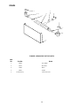
1
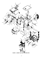
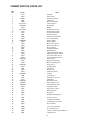
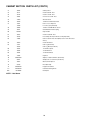
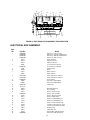
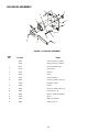
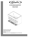
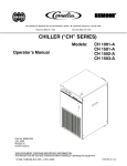
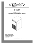
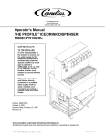
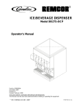
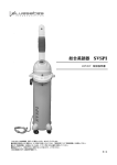
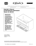
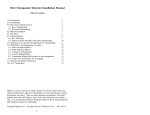
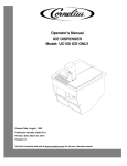
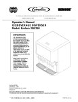
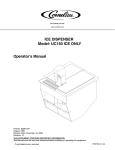
CORNELIUS INC
www.cornelius.com
ICE/BEVERAGE DISPENSER
MODEL: TRIAD–150
Operator’s Manual
Release Date: May 01, 1998
Publication Number: 620911101
Revision Date: May 07, 2014
Revision: D
THIS DOCUMENT CONTAINS IMPORTANT INFORMATION
This Manual must be read and understood before installing or operating this equipment
© CORNELIUS INC; 1998-2014
PRINTED IN U.S.A
TABLE OF CONTENTS
Page
MAINTENANCE . . . . . . . . . . . . . . . . . . . . . . . . . . . . . . . . . . . . . . . . . . . . . . . . . . . . . . . . . . .
1
DAILY (OR AS REQUIRED) . . . . . . . . . . . . . . . . . . . . . . . . . . . . . . . . . . . . . . . . . . . . .
1
WEEKLY (OR AS REQUIRED) . . . . . . . . . . . . . . . . . . . . . . . . . . . . . . . . . . . . . . . . . .
1
MONTHLY . . . . . . . . . . . . . . . . . . . . . . . . . . . . . . . . . . . . . . . . . . . . . . . . . . . . . . . . . . . .
1
START-UP & OPERATING INSTRUCTIONS . . . . . . . . . . . . . . . . . . . . . . . . . . . . . .
1
CLEANING INSTRUCTIONS . . . . . . . . . . . . . . . . . . . . . . . . . . . . . . . . . . . . . . . . . . . .
1
DISPENSER . . . . . . . . . . . . . . . . . . . . . . . . . . . . . . . . . . . . . . . . . . . . . . . . . . . . . . . . . .
2
BEVERAGE SYSTEM (IF APPLICABLE) . . . . . . . . . . . . . . . . . . . . . . . . . . . . . . . . .
3
TROUBLESHOOTING . . . . . . . . . . . . . . . . . . . . . . . . . . . . . . . . . . . . . . . . . . . . . . . . . . . . . .
5
BLOWN FUSE OR CIRCUIT BREAKER. . . . . . . . . . . . . . . . . . . . . . . . . . . . . . . . . . .
5
GATE DOES NOT OPEN. AGITATOR DOES NOT TURN. . . . . . . . . . . . . . . . . . .
5
GATE DOES NOT OPEN OR IS SLUGGISH. AGITATOR TURNS. . . . . . . . . . .
5
ICE DISPENSES CONTINUOUSLY. . . . . . . . . . . . . . . . . . . . . . . . . . . . . . . . . . . . . . .
5
SLUSHY ICE. WATER IN HOPPER. . . . . . . . . . . . . . . . . . . . . . . . . . . . . . . . . . . . . .
5
BEVERAGES DO NOT DISPENSE. . . . . . . . . . . . . . . . . . . . . . . . . . . . . . . . . . . . . . .
5
BEVERAGES TOO SWEET. . . . . . . . . . . . . . . . . . . . . . . . . . . . . . . . . . . . . . . . . . . . .
5
BEVERAGES NOT SWEET ENOUGH. . . . . . . . . . . . . . . . . . . . . . . . . . . . . . . . . . . .
6
BEVERAGES NOT COLD (UNITS WITH BUILT-IN COLD PLATE). . . . . . . . . . . .
6
PARTS LIST / EXPLODED VIEW . . . . . . . . . . . . . . . . . . . . . . . . . . . . . . . . . . . . . . . . . . . .
7
CABINET SECTION PARTS LIST . . . . . . . . . . . . . . . . . . . . . . . . . . . . . . . . . . . . . . .
9
ELECTRICAL BOX ASSEMBLY . . . . . . . . . . . . . . . . . . . . . . . . . . . . . . . . . . . . . . . . .
11
SOLENOID ASSEMBLY . . . . . . . . . . . . . . . . . . . . . . . . . . . . . . . . . . . . . . . . . . . . . . . .
12
DRAIN . . . . . . . . . . . . . . . . . . . . . . . . . . . . . . . . . . . . . . . . . . . . . . . . . . . . . . . . . . . . . . . .
13
LIST OF FIGURES
FIGURE 1. CABINET SECTION EXPLODED VIEW . . . . . . . . . . . . . . . . . . . . . . . .
8
FIGURE 2. ELECTRICAL BOX ASSEMBLY EXPLODED VIEW . . . . . . . . . . . . . .
11
FIGURE 3. SOLENOID ASSEMBLY . . . . . . . . . . . . . . . . . . . . . . . . . . . . . . . . . . . . . .
12
FIGURE 4. DRAIN FOR Z STYLE UNITS . . . . . . . . . . . . . . . . . . . . . . . . . . . . . . . . .
13
MAINTENANCE
The following dispenser maintenance should be performed at the intervals indicated:
DAILY (or as required)
Remove foreign material from vending area drip tray to prevent drain blockage.
WEEKLY (or as required)
Clean vending area. Check for proper water drainage from the vending area drip tray.
MONTHLY
Clean and sanitize the hopper interior and beverage system, if applicable (see CLEANING INSTRUCTIONS).
START-UP & OPERATING INSTRUCTIONS
Fill the hopper with ice. Dispense several large cups of ice (approximately 20 to 30 seconds total dispensing
time) to allow ice to fill the cold plate cabinet. Add ice to the hopper as necessary to refill and replace the lid. Allow 10 to 15 minutes for the cold plate to cool down. Repeat this procedure whenever the dispenser has run out
of ice. Start up the beverage system and adjust faucets to the proper brix. Contact your local syrup distributor for
complete information on the beverage system.
In normal operation, pushing the ice dispenser mechanism will cause ice to flow from the ice chute. Ice flow will
continue until the dispenser mechanism is released. Dispensing of any faucet will provide beverage of the appropriate flavor.
CAUTION: Use caution to avoid spilling ice when filling dispenser. Clean up immediately any
spilled ice from filling or operating the unit. To prevent contamination of ice, the lid must be
installed on the unit at all times.
If the dispenser fails to dispense ice or beverage see troubleshooting guide.
CLEANING INSTRUCTIONS
WARNING: Disconnect Power Before Cleaning! Do not use metal scrapers, sharp objects or
abrasives on the ice storage hopper, top cover and the agitator disk, as damage may result.
Do not use solvents or other cleaning agents, as they may attack the plastic material.
Soap solution - Use a mixture of mild detergent and warm (100 F) potable water.
Sanitizing solution - Use 1/2 ounce of household bleach in 1 gallon of potable water. Preparing the sanitizing
solution to this ratio will create a solution of 200 PPM.
1
DISPENSER
1. CLEANING EXTERIOR SURFACES
Important: Perform the following daily.
A.
Remove the cup rest from drip tray.
B.
Wash the drip tray with soap solution. Rinse with clean water and allow solution to run down the drain.
C.
Wash cup rest with soap solution and rinse in clean water. Install the cup rest into the drip tray.
D.
Clean all exterior surfaces with soap solution and rinse in clean water.
2. COLD PLATE INSPECTION BEFORE CLEANING
A.
Remove splash panel.
B.
Remove the plastic cold plate cover to expose the cold plate.
C.
Locate and remove any debris from the cold plate, drain trough and make certain that the drain holes
are not clogged.
D.
Reinstall the cold plate cover.
E.
Reinstall the splash panel in the reverse order in which it was removed.
3. CLEANING INTERIOR SURFACES
CAUTION: When pouring liquid into the hopper, do not exceed the rate of 1/2 gallon per
minute.
Important: Perform the following at least once a month.
A.
Remove agitator assembly.
B.
Using a long handle nylon bristle brush, clean the interior of the hopper, top, cover and cold plate with
soap solution. The cold plate can be reached by going through the ice opening on the hopper bottom.
Make certain to reach the entire surface of the cold plate including the corners. Clean the agitator assembly with soap solution using a nylon brush or a sponge. Thoroughly rinse the hopper, top cover,
agitator and cold plate surfaces with clean potable water.
C.
Remove merchandiser and ice chute cover from dispenser.
D.
With a nylon bristle brush or sponge, clean the inside of the ice chute, gasket and cover with soap
solution and rinse thoroughly to remove all traces of detergent.
E.
Re-assemble Agitator assembly. Take special care to ensure that the thumbscrew is tight.
F.
Using a mechanical spray bottle filled with sanitizing solution, spray the entire interior and agitator assembly. Allow to air dry.
G.
Re-assemble ice chute assembly.
H.
Using a mechanical spray bottle filled with sanitizing solution, spray the inside of the ice chute. Allow
to air dry.
I.
Reinstall merchandiser.
2
BEVERAGE SYSTEM
(IF APPLICABLE)
WARNING: Disconnect Power Before Cleaning! Do not use metal scrapers, sharp objects
or abrasives on the ice storage hopper, top cover and the agitator disk, as damage may
result. Do not use solvents or other cleaning agents, as they may attack the plastic material.
Soap solution - Use a mixture of mild detergent and warm (100 F) potable water.
Sanitizing solution - Use 1/2 ounce of household bleach in 1 gallon of potable water. Preparing the sanitizing
solution to this ratio, the required solution of 200 PPM will be obtained.
Cleaning tank - Fill clean, empty tank with a mixture of mild detergent and five (5) gallons of warm
potable water (120°F).
1. DISPENSING VALVES
Refer to addendum supplied with the unit that is applicable to the manufacturer of the valves installed
on the unit.
2. PRODUCT TUBING
Only trained and qualified persons should perform these cleaning and sanitizing procedures.
A.
Sanitize tank systems, Post-Mix and Pre-Mix
a.
Remove all the quick disconnects from all the tanks. Fill a suitable pail or bucket with
soap solution.
b.
Submerge all disconnects (gas and liquid) in the soap solution and then clean them using a nylon
bristle brush. (Do not use a wire brush). Rinse with clean water.
c.
Prepare sanitizing solution and using a mechanical spray bottle, spray the disconnects.
Allow to air dry.
d.
Using a clean, empty tank, prepare five (5) gallons of the sanitizing solution. Rinse the tank disconnects with approximately 9 oz. of the sanitizing solution. Close the tank.
e.
Prepare cleaning tank by filling clean five (5) gallon tank with a mixture of mild detergent and potable water (120_F).
f.
Connect a gas disconnect to the tank and then apply one of the product tubes to the cleaning
tank. Operate the appropriate valve until liquid dispensed is free of any syrup.
g.
Disconnect cleaning tank and hook up sanitizing tank to syrup line and CO2 system.
h.
Energize beverage faucet until chlorine sanitizing solution is dispensed through the faucet. Flush
at least two (2) cups of liquid to ensure that the sanitizing solution has filled the entire length of
the syrup tubing.
i.
Allow sanitizer to remain in lines for fifteen (15) minutes.
j.
Repeat the step above, applying a different product tube each time until all tubes are filled with
the sanitizing solution.
k.
For post-mix valves, remove the nozzle and syrup diffuser and clean them in a mild soap solution.
Rinse with clean water and reassemble the nozzle and syrup diffuser to the valve.
l.
For pre-mix valves, disconnect all product tubes from the tank of sanitizing solution and then
open the valves to allow the pressure to be relieved. Remove the valves from the dispenser, disassemble and wash thoroughly in a mild soap solution.
m.
Rinse the parts in clean water, reassemble the valve and reconnect it to the dispenser.
3
n.
B.
Discard the tank of sanitizing solution and reconnect the product (syrup or pre-mix) tanks. Operate the valves until all sanitizer has been flushed from the system and only product (syrup or premix) is flowing.
Sanitize syrup lines, B-I-B Systems
a.
Remove all the quick disconnects from all the B-I-B containers.
b.
Fill a suitable pail or bucket with soap solution.
c.
Submerge all disconnects (gas and liquid) in the soap solution and then clean them using a nylon
bristle brush. (Do not use a wire brush). Rinse with clean water.
d.
Using a plastic pail, prepare approximately five (5) gallons of sanitizing solution.
e.
Rinse the B-I-B disconnects in the sanitizing solution.
f.
Sanitizing fittings must be attached to each B-I-B disconnect. If these fittings are not available,
the fittings from empty B-I-B bags can be cut from the bags and used. These fittings open the
disconnect so the sanitizing solution can be drawn through the disconnect.
g.
Place all the B-I-B disconnects into the pail of sanitizing solution. Operate all the valves until the
sanitizing solution is flowing from the valve. Allow sanitizer to remain in lines for fifteen
(15) minutes.
h.
Remove the nozzle and syrup diffuser from each valve and clean them in a soap solution. Rinse
with clean water and reassemble the nozzle and syrup diffuser to the valve.
i.
Remove the sanitizing fittings from the B-I-B disconnects and connect the disconnects to the appropriate B-I-B container. Operate the valves until all sanitizer has been flushed from the system
and syrup is flowing freely.
4
TROUBLESHOOTING
IMPORTANT: Only qualified personnel should service internal components or electrical wiring.
WARNING: If repairs are to be made to a product system, remove quick disconnects from
the applicable product tank, then relieve the system pressure before proceeding. If repairs
are to be made to the CO2 system, stop dispensing, shut off the CO2 supply, then relieve the
system pressure before proceeding. If repairs are to be made to the refrigeration system, make sure
electrical power is disconnected from the unit.
Should your unit fail to operate properly, check that there is power to the unit and that the hopper contains ice. If the unit does not dispense, check the following chart under the appropriate symptoms to aid
in locating the defect.
Trouble
Probable Cause
BLOWN FUSE OR CIRCUIT BREAKER.
GATE DOES NOT OPEN. AGITATOR DOES
NOT TURN.
GATE DOES NOT OPEN OR IS SLUGGISH.
AGITATOR TURNS.
ICE DISPENSES CONTINUOUSLY.
SLUSHY ICE. WATER IN HOPPER.
BEVERAGES DO NOT DISPENSE.
BEVERAGES TOO SWEET.
5
A.
Short circuit in wiring.
B.
Defective gate solenoid.
C.
Defective agitator motor.
A.
No power.
B.
Bent depressor plate (does not actuate switch).
C.
Defective dispensing switch.
A.
Defective gate solenoid.
B.
Excessive pressure against gate slide.
C.
Defective rectifier.
A.
Stuck or bent depressor plate (does not
release switch).
B.
Defective dispensing switch.
C.
Improper switch installation.
A.
Blocked drain.
B.
Unit not level.
C.
Poor ice quality due to water quality or
icemaker problems.
D.
Improper use of flaked ice.
A.
No 24 volt power to faucets.
B.
No CO2 pressure.
A.
Carbonator not working.
B.
No CO2 pressure in carbonator.
C.
Faucet brix requires adjusting.
Trouble
BEVERAGES NOT SWEET ENOUGH.
BEVERAGES NOT COLD (UNITS WITH BUILT-IN
COLD PLATE).
Probable Cause
A.
Empty syrup tank.
B.
Faucet brix requires adjusting.
A.
Unit standing with no ice in hopper – no ice in
cold plate cabinet.
Contact your local syrup or beverage equipment distributor for additional information and troubleshooting of beverage system.
6
PARTS LIST / EXPLODED VIEW
7
34
16
38
4
39
22
1
33
26
49
7
24
45
43
23
2
58
28
66
47
32
54
27
50
51
30
54
51
20
59
68
46
21
17
52
54
67
3
5
52
36
64
42
53
54
14
6
52
40
14
18
64
35
25
61
61
63
57
9
72
BEV PANEL PEPSI
44
64
BEV PANEL PEPSI
31
48
8
12
11
10
52
69
29
10
41
13
57
19
37
60
15
FIGURE 1. CABINET SECTION EXPLODED VIEW
8
52
CABINET SECTION PARTS LIST
Index
No.
1
2
3
4
5
6
7
8
9
10
11
12
13
14
15
16
17
Part No.
21491
22081
29303R
15346
29483
Contact Sales
620019001
29313
Contact Sales
27107
10145
31007
50099
50767
620034009
15087
30794
32826
Name
Gate Slide
Gate Restrictor
Plate, Motor Mounting
Agitator Assy
Cover, Rear Wrapper
Lower Panel Assy
Electrical Box
Wrapper
Panel C/P Faucet Assy
Bracket, Depressor Mtg.
Pin, Drip Tray Mounting
Switch Boot (Clear)
Insulation, Cold Plate Drain
Heyco Snap Bushing
Drip Tray lift Out
Retainer, Agitator
Motor Heater, 115 Volt
Motor Heater, 230 Volt
18
19
20
21
30895
53011
31622
32498
32824
Dispense Switch
Coldplate Drain Elbow
Bulb-Daylight 10”
Agitator Motor DB150, 115 Volt
Agitator Motor DB 150, 230 Volt
22
32954
33409
Solenoid Assembly, 115 Volt
Solenoid Assembly, 230 Volt
23
24
25
26
27
28
29
30
31
32
33
34
35
36
37
38
39
620019101
29304
71010
620019701
51859
51891
51908
52876
620500901
53168
53241
53227
620506702
84146040
62050850
53019
52872
40
15437
Baffle, Wiring Encl.
41
52967
Plug, Plastic
Reflector Panel
Bracket, Motor Mounting
Washer, Captivating No. 8
Hinge, Gusset
Seal Motor Shaft
Gasket, Gate
Plug, Heyco D
Gasket, Motor Shaft
Ice Chute
Ice Chute Cover
Cold Plate Access Cover
Agitator Disk
Merchandiser, Gray
Panel, Plexiglass, Inner
Foamed Sink Assy, Gray
Lid, Dispenser, Gray
Hopper Assy., Foamed
42
52972
Flush Nylon Clip (Graphics)
43
53236
Cover C.P. Foamed
44
70016
# 10-32 Hex Nut 18-8SS
45
70017
# 10-32 Nylon Insert Locknut
46
70018
Nut, 1/4-20 Keps
47
70048
1/4 Int. Tooth Lockwasher
48
70056
No. 10 Flatwasher SS
49
70067
7/32 I.D. x 7/8 O.D. x 3/64 Thk Washer
50
70076
# 8-32 Keps Nut
9
CABINET SECTION PARTS LIST (CONT’D)
51
70456
3/16 Pop Rivet
52
70171
# 8-32 x 3/8 Phil. Truss
53
70178
# 8-32 x 1/2 Phil. Truss
54
70204
# 8 x 1/2 A S.S. Phil. Truss
55
71089
Shoulder Screw
56
70250
1/4-20 Truss HD Phil Screw SS
57
15501
15500
Push Lever, Ice Dispense
Lever Ass’y (Cup Activated)
58
70260
1/4-20 x 1 Phil RD HD S.S. Screw
59
70341
Gate Slide/Motor Heater Spring
60
70478R
61
70555
# 8-32 x 2-5/8 Phil. Truss
62
70750
Hose Clamp, Worm (Not Shown; for Drip Tray Drain)
63
71006
8-32 x 2-1/8 Phil. Truss Screw(Only used on Units with Lancer
Valves)
64
70959
# 8-32 Hex Nutsert
65
71011
70970
Cast Leg (Not Shown)
Cast Leg, Black (Not Shown)
66
70992
1/4 Turn Receptacle
67
70993
1/4 Turn Retainer
68
70994
1/4 Turn Stud Head
69
71036
Cup Rest
70
620029501
Adapter, 1” Barb x 3/4 M.P.T. (Not Shown)
71
50952
Adapter, 3/4 soc x 3/4 F.P.T. (Not Shown)
72
70847
Washer, Switch Spacer
73
53299
Flush Nylon Clip
Clip, Push On
74
620505201
Hopper Foam Shield
75 *
620702201
Cold Plate Cleaning Brush
N/A*
84146040
CC Graphic
NOTE: * Not Shown
10
18
17
16
22
15
3
19
2
10
22
8
5
22
13
4
11
19
7
6
9
11
19
22
1
FIGURE 2. ELECTRICAL BOX ASSEMBLY EXPLODED VIEW
ELECTRICAL BOX ASSEMBLY
Item
No.
1
2
3
4
5
6
7
8
9
10
11
12
13
14
15
Part No.
Name
620303301
620302001
620302301
620303302
30514
30774
32831
30995
620302901
31107
31620
31621
33662
620314803
620314802
620302201
32682
32829R
620302101
Not Used
50458
50459
33615
620301101
E-Box Ass’y, 115V (Ice only)
E-Box Ass’y, 115V (B and BC Models)
E-Box Ass’y, 220V (B and BC Models)
E-Box Ass’y, 220V (Ice only)
Clamp, Capacitor
Capacitor, 120 Volt
Capacitor, 240 Volt
Power Cord Assy, 120 Volt
Power Cord Ass’y, 240 Volt
Terminal Board
Starter
Ballast, 120 Volt
Ballast, 240 Volt
Timer, Repeat Cycle, 120 Volt
Timer, Repear Cycle, 240 Volt
Socket, Starter
Transformer, 120/24, 80VA
Transformer, 240/24 80 VA
Lamp-holder
Strain Relief Bushing
Heyco Bushing
Harness, Solenoid, 115V
Harness, Solenoid, 220V
16
17
18
32782
33617
70147
Harness, Dispenser Switch
Harness, Agitator Motor
#6-32 x 1/2 Phil RD HD Screw
19
20
21
70153
70217
70120
70239
#6-32 x 3/4 Phil RD HD Screw
#8-32 x 1/2 Hex SL Washer HD
# 10-32 x 1/2 Ground Screw, 115V
# 10-32 x 3/4 Ground Screw, 220V
22
23
24
25
70075
70015
32244
620304601
#6-32 Keps Nut
#10-32 Keps Nut
Terminal Strip, 220V (Not Shown)
VA Resistor, 220V (Not Shown)
11
SOLENOID ASSEMBLY
13
1
4
10
3
7
14
4
12
9
11
6
8
2
5
FIGURE 3. SOLENOID ASSEMBLY
Item
No.
Part No.
Name
32954
Gate Solenoid Ass’y, 120 Volt
33397
Gate Solenoid Ass’y, 240 Volt
1
28172
Plate, Solenoid Mounting
2
28173
Arm, Gate Lift
3
32957
Solenoid
4
50752
Isolator
5
50754
Bearing, Gate Arm
6
70162
Screw, No. 8-32 By 1/4-In. Long
7
70015
Hex Nut, No. 10-32
8
51689
Locktite
9
70165
Screw, No. 8-32 By 5/8-In. Long
10
70057
Lockwasher, No. 10
11
70067
Washer, .218 I.D. By .875 O.D.
12
51348
Spacer
13
71007
Spring, Solenoid Arm
14
70052
Flatwasher, No. 8
12
DRAIN
1
1
3
4
2
1
1
3
5
FIGURE 4. DRAIN FOR Z STYLE UNITS
Item
No.
Part No.
1
70750
Hose Clamp
2
53170
Drain Tube
3
51280
Elbow
4
53293
Coupler
5
Contact Factory
Name
Lower Front Panel
13
CORNELIUS INC.
www.cornelius.com