1
WIRING THE MATRIX TO AN EXTERNAL
ALARM
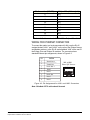
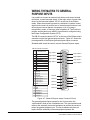
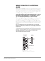
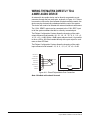
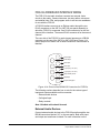
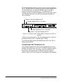
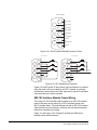
With the Alarm I/O DB-9F connector, an external alarm device can be
connected to monitor failures in the matrix. Pins are also available for
connecting an external alarm source to the matrix’s Alarm System. For
details on the functions that are monitored by the Alarm System refer
to the Eclipse Omega or Eclipse Median Manuals.
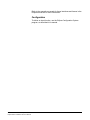
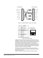
A failure will activate the relay contacts connected to pins 4, 5, and 9 of
the connector. These contacts are “dry”, and are rated at 1 A at 24
VDC. They are not recommended for AC mains line current.
Pins are provided for adding an additional alarm source to the matrix’s
alarm system. Pin 6 is an alarm input to the Eclipse matrix. It is
connected to the input of a 3.3 volt logic device. A logic high on this
input will cause the Eclipse matrix to detect an alarm condition. A logic
low or an open circuit will cause the Eclipse matrix to detect no alarm
condition.
Pin 1 is a voltage source out of the Eclipse matrix. It is connected
through a 10k ohm pull-up resistor to the +5 volt supply rail inside the
Eclipse matrix.
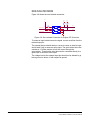
A contact closure placed across pins 1 and 6 will also cause an alarm
condition. The alarm outputs of the PSU-101 could be wired directly to
these pins allowing the CPU card to report PSU failures also.
Note: Shielded cable should be used.
System 200/COM-72
"Alarm I/O" DB-9F
Connector
1
6
2
PSU-101
"Alarm Relay"
Connector
1
To Alarm
2
To Alarm
3
7
4
3
8
4
Relay Normally Closed
9
5
Relay Wiper
Relay Normally Open
Figure 4-10: Alarm I/O Connector
Clear-Com Communication Systems
Eclipse Matrix Installation Instruction Manual
4-15