1
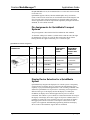
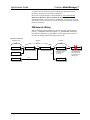
Crestron MediaManager™
Control, Switching and Management
Applications Guide
This document was prepared and written by the Technical Documentation department at:
Crestron Electronics, Inc.
15 Volvo Drive
Rockleigh, NJ 07647
1-888-CRESTRON
All brand names, product names and trademarks are the property of their respective owners.
©2004 Crestron Electronics, Inc.
Crestron MediaManager™
Applications Guide
Contents
Crestron MediaManager™ Applications Guide
1
Introduction ..........................................................................................................1
The QuickMedia™ Transport System....................................................1
Pin Assignments for QuickMedia Transport Systems............................3
Display Device Selection for a QuickMedia System .............................3
QM Network Wiring ..............................................................................4
QuickMedia Equipment........................................................................................5
Wall Plate Media Centers.......................................................................5
FlipTop Boxes........................................................................................7
Receivers/Processors............................................................................13
Distribution Centers .............................................................................21
Amplifiers ............................................................................................30
Keypads................................................................................................31
Touchpanels .........................................................................................32
MediaManager™ Device Feature Chart .............................................33
MediaManager Applications/Solutions ..............................................................34
MediaManager for Schools ..................................................................34
MediaManager for Business.................................................................35
MediaManager Configuration Software .............................................................38
Configuring with Crestron SystemBuilder™ .......................................38
SystemBuilder Audio Scenarios...........................................................42
Digital Media Tools™ .........................................................................49
Crestron RoomView™ Remote Management Software.....................................53
Appendix: Crestron Cable ..................................................................................56
Applications Guide – DOC. 6244
Contents • i
Crestron MediaManager™
Applications Guide
Crestron MediaManager™
Applications Guide
Introduction
This guide is designed to provide you with an introduction to the new Crestron
MediaManager™ product line, the next generation of simplified A/V room
switching and system control products. This document contains fundamental
information about the technology, available components, general system
organization, and application concepts of MediaManager systems.
MediaManager integrates all the following in a single family of products.
•
A/V device control
•
Facility-wide management
•
Simple installation
•
Low cost wiring
•
High quality signal switching, processing, and routing
The flexible MediaManager product line can address all of your A/V needs,
from a single room up to a campus-wide or facility-wide network. The
MediaManager solution is both scalable and adaptable as a new system or as an
upgrade to an existing system.
MediaManager can accept a traditional signal management solution with coaxbased signal routing and switching, or the more modern CAT5E/UTP signal
routing technologies.
All MediaManager products incorporate integrated Ethernet control. This allows
control via LAN, WAN or the Internet, of the A/V equipment connected through
any MediaManager solution.
The QuickMedia™ Transport System
Using a new, proprietary signal routing solution, signals such as composite
video, S-video, RGBHV, audio, microphone and control, are all transported
using a single cable solution called QuickMedia™ (QM).
The QuickMedia Transport System port is capable of managing computer,
video, and audio signals simultaneously through one CAT5E/UTP wire,
simplifying MediaManager installations.
Applications Guide – DOC. 6244
Crestron MediaManager™ • 1
Applications Guide
Crestron MediaManager™
Routing CAT5E/UTP cable is less expensive and much simpler than routing
multi-colored, multi-conductor coax cable. All Crestron® products using the
QuickMedia Transport System are capable of sending and receiving
QuickMedia signals via standard CAT5E/UTP cable. Crestron recommends
Belden Media-Twist cable, and Crescat-QM. Installation of any QuickMedia
device is as simple as installing one set of QuickMedia wires from output to
input. Installations are flexible, affordable, and fast.
The Crescat-QM cable contains one CAT5E cable and one Cresnet® cable in a
siamese jacket.
QuickMedia Cable – CRESCAT-QM
The QuickMedia receiver performs frequency compensation on each video input
for skew. Signal skew occurs when part of the signal is delayed with respect to
other signal components. The amount of skew largely depends on the length of
the QuickMedia cable. Unequal wire lengths are created because CAT5 consists
of twisted pairs that are twisted together in the cable.
The total accumulated skew from QM transmitter to QM receiver must not
exceed 15 ns (nanoseconds). Crestron recommends a cable with a rating of less
than or equal to 15 ns over its entire length.
For example, if using a cable with a rating of 15 ns/100 meters (100 meters =
328 feet), connecting the QM-WMC/QM-WMIC QM transmitter with 150 feet
of cable to a QM-MD7x2 switcher, and then using another 150 feet to connect
2 • Crestron MediaManager™
Applications Guide – DOC. 6244
Crestron MediaManager™
Applications Guide
the QM-RMCRX receiver, the accumulated skew over the entire 300 feet should
not exceed 15 ns.
QuickMedia supports UXGA (Ultra Extended Graphics Array) resolutions
(1600 x 1200 at 60 Hz vertical rate) at its maximum allowed cable length of 300
feet. The same path is used for the transport of composite and S-video which
ensures support that exceeds the requirements imposed by the highest broadcast
standards, as well as NTSC and PAL.
Pin Assignments for QuickMedia Transport
Systems
The pin assignment is based on the EIA/TIA 568B RJ-45 Jack standard.
To determine which pin is number 1, hold the cable so that the end of the eight
pin modular jack is facing you, with clip down and copper side up. When
looking down at the copper connections, pin 1 is on the far right.
QuickMedia Pin and Pair Assignment
RJ-45 MALE
CONNECTOR
RJ-45
PIN #
CAT5E
PAIR #
WIRE COLORS
QM
ASSIGNMENT
RGB AND
AUDIO
QM
ASSIGNMENT
COMPOSITE,
S-VIDEO AND
AUDIO
- RGB Red
- Chrominance
1
2
White/Orange
2
2
Orange
+ RGB Red
+ Chrominance
3
3
White/Green
- RGB Green
- Luminance
4
1
Blue
+ Audio
+ Audio
5
1
White/Blue
- Audio
- Audio
6
3
Green
+ RGB Green
+ Luminance
7
4
White/Brown
- RGB Blue
- Composite
8
4
Brown
+ RGB Blue
+ Composite
Display Device Selection for a QuickMedia
System
QuickMedia fully integrates the display device with the system. Consequently,
careful selection of a display device is required to take full advantage of this
capability. A projector should support discrete video switching commands. This
enables the QuickMedia receiver/processor to seamlessly pass along the three
different video types to the display and alert the display to switch inputs.
In addition, the display device should support discrete power on and off
commands. This enables a system “Room On” button function that will energize
the display. If the display device has a toggle on/off power command, there is a
possibility of getting out of sync with the room power. An option for displays
that toggle power on/off is to use the Crestron power sensor, however this
requires extra equipment and additional programming. Most RS-232 display
drivers in the Crestron database support discrete commands.
Applications Guide – DOC. 6244
Crestron MediaManager™ • 3
Applications Guide
Crestron MediaManager™
To achieve the best solution the projector should also support lamp hours
monitoring, allowing for better facility management.
Refer to the Crestron Database in System Builder or www.crestron.com |
Dealer/Tech Resources | Whose Products Do We Control? for a list of
supported products. You may search by manufacturer or device type. You may
also call the Crestron customer service team or check our online help system for
the latest information.
QM Network Wiring
When connecting multiple QM devices, the route between a QM origination
point (e.g., QM-WMC) and a QM endpoint (e.g., QM-RMCRX) cannot have
more than two midpoints (e.g., QM-MD7x2 or other QM switchers). Refer to
the following diagram when configuring a QM network.
QM Network Topology
Origination Points
QM-WMC
Midpoints
QM
QM-MD7x2
QM
Endpoints
QM
QM-MD7x2
QM
QM-WMC
QM-FTMC
QM
QM
4 • Crestron MediaManager™
QM-MD7x2
QM-MD7x2 acts as
an endpoint for
audio only.
QM
X
QM-RMCRX
This QM-RMCRX
cannot be used as
it violates the twomidpoint rule.
QM-RMCRX
Applications Guide – DOC. 6244
Crestron MediaManager™
Applications Guide
QuickMedia Equipment
Adding a MediaManager wall plate or a FlipTop box anywhere in a room
creates a fully integrated system, because these devices connect to Cresnet,
Crestron’s control protocol. With the addition of a QuickMedia receiver and
keypad or touchpanel, you create a complete integrated room solution.
Wall Plate Media Centers
The Wall Plate Media Center (QM-WMC) and Wall Plate Media Center with
Microphone Input (QM-WMIC) are part of Crestron’s MediaManager line of
network devices, room control systems and signal routing solutions.
The QM-WMC is a wall-mounted, double-gang, Cresnet device that uses
QuickMedia technology to facilitate an uncomplicated connection of audio,
video, and computer equipment to the Crestron line of room control systems.
The QM-WMC installs into a wall using standard electrical double-gang boxes
and decorator style faceplates (sold separately).
The QM-WMIC is an optional device that links to the QM-WMC. It adds two
Neutrik™ Combo microphone inputs with switchable phantom power to the
QM-WMC and extends the QM-WMC to 3-gang box. The QM-WMIC requires
the purchase and installation of the QM-WMC.
NOTE: The QM-WMIC only mounts on the right side of the QM-WMC.
All media and control signals are routed via a single QuickMedia cable for
simple installation. The QM-WMC can be combined in a multi-gang electrical
box with Crestron’s C2N-DB6/8/12 decorator-style keypads for additional room
control functions such as source selection, lighting, and volume.
QM-WMC and QM-WMIC Wall Plate
Applications Guide – DOC. 6244
QM-WMC/WMIC and C2N-DB8 Wall Plate
Crestron MediaManager™ • 5
Applications Guide
Crestron MediaManager™
QM-WMC with QM-WMIC Block Diagram
6 • Crestron MediaManager™
Applications Guide – DOC. 6244
Crestron MediaManager™
Applications Guide
FlipTop Boxes
The five different QuickMedia FlipTop boxes (described on the following
pages) are simple to install, and provide easy access to the QuickMedia system.
All FlipTop boxes are available in either a black or brushed aluminum finish,
and all provide video sync sensing on all inputs. Refer to the following charts
for an explanation of features and a block diagram of each FlipTop box.
FlipTop Comparison Chart
FEATURE
Engravable *
Buttons with
LEDs
Front Panel
Inputs and
Outputs
QM-FTMC
QM-FTCC
QM-FTSC
QM-FTDC
QM-FTMCSC
FLIPTOP MEDIA
CENTER
FLIPTOP
COMPUTER
CENTER
FLIPTOP MEDIA
CENTER WITH
CABLE STORAGE
COMPARTMENT
FLIPTOP
DATA
CENTER
FLIPTOP MEDIA
CENTER WITH
CABLE
STORAGE
COMPARTMENT
FlipTop Lid
Mounted, 10 to 20
Buttons*
• DB15HD RGB
with mini TRS
stereo audio
• RCA Composite
Video with stereo
audio
• 4-pin Mini-DIN Svideo with stereo
audio
• RJ-45 LAN PassThrough
• AC Power PassThrough
FlipTop Lid Mounted,
10 to 20 Buttons*
Front Panel Mounted,
6 Buttons*
FlipTop Lid
Mounted, 10
to 20 Buttons*
FlipTop Lid
Mounted, 10 to 20
Buttons*
• DB15HD RGB with
mini stereo audio
• RJ-45 LAN PassThrough
• AC Power PassThrough
AC Power PassThrough
Includes QM-FTCMK
Cable Plate Kit
• DB15HD
RGB with
mini stereo
audio
• Two RJ-11
Phone
PassThrough
• Two RJ-45
LAN PassThrough
• AC Power
PassThrough
• RCA Composite
Video with stereo
audio
• Mini-DIN S-video
with stereo audio
• AC Power PassThrough
• AC Power Cord
• DB15HD RGB with
mini TRS stereo
audio via Cable
• DB15HD RGB
Buffered Monitor
Output
• RCA Composite
Video with stereo
audio via Cable
• Mini-DIN S-video
with stereo audio
via 36” Cable
• Two Neutrik
Combo Phantom
Powered Mic Inputs
• RJ-45 QuickMedia
Output Port
• Terminal Block
Cresnet Port
• AC Power
Cord
• Two
Terminal
Block
Phantom
Powered
Mic Inputs
• RJ-45
QuickMedia
Output Port
• Terminal
Block
Cresnet Port
• Optional
QM-FTCMK
Cable/Plate
kit
• AC Power Cord
• DB15HD RGB
with mini TRS
stereo audio via
36” Cable
• Two Terminal
Block Phantom
Powered Mic
Inputs
• RJ-45
QuickMedia
Output Port
• Terminal Block
Cresnet Port
-
3X1 A/V Switcher
with Audio
Breakaway
Bottom Inputs
and Outputs
• AC Power Cord
• Two Terminal
Block Phantom
Powered Mic
Inputs
• RJ-45
QuickMedia
Output Port
• RJ-45 LAN
Pass-Through
• Two Terminal
Block Cresnet
Ports
• TouchSettable
ID Button and
LED
• Optional QMFTCMK
Cable/Plate kit
• AC Power Cord
• Two Terminal Block
Phantom Powered
Mic Inputs
• RJ-45 QuickMedia
Output Port
• RJ-45 LAN PassThrough
• Two Terminal Block
Cresnet Ports
• TouchSettable ID
Button and LED
• Optional QMFTCMK
Cable/Plate kit
A/V Switcher
3X1 A/V Switcher
with Audio
Breakaway
-
3X1 A/V Switcher
with Audio
Breakaway
*As an option, custom-engraved buttons can be designed and obtained by using the
Crestron Engraver software. Version 2.2.1.1 and the required Cresnet database version
16.3.0 or later are available from the Downloads | Software Updates section of the
Crestron website (www.crestron.com <http://www.crestron.com>).
Applications Guide – DOC. 6244
Crestron MediaManager™ • 7
Applications Guide
Crestron MediaManager™
QM-FTMC FlipTop Media Center
Features
• Built-in keypad with up to 20 engravable
buttons
• Programmable LED Bar Graphs, Power and
Net indicators
• 3 X 1 video switch with sync sensing (1
composite connector, 1 S-video connector, 1
RGBHV connector)
• 3 X 1 audio switch (2 stereo RCA, 1 stereo
1/8” mini jack)
• One RJ-45 Ethernet port passthrough.
• One AC power passthrough
• Connections on the underside of the QMFTMC:
– Two Mini Connector Mic inputs with
phantom power
– One QuickMedia RJ-45 connector
– Two Cresnet Mini Connectors
– One RJ-45 Ethernet Passthrough
Connector
– Optional QM-FTCMK Cable/Plate kit
RJ-45
Ethernet
Keypad
AC Power
3X1
Audio
Switch
Computer Audio
A/D
Converter
S-Video Audio
Composite Video
Audio
3X1
Video
Switch
Computer RGB
Video
Sync
Sensing
S-Video
Composite Video
8 • Crestron MediaManager™
AC Power
RJ-45
Ethernet
QM Output
Cresnet
A/D
Converter
MIC 1
MIC 2
Program L
Program R
Video
Microphone 2
Phantom Power
Microphone 1
Input
Gain
Applications Guide – DOC. 6244
Crestron MediaManager™
Applications Guide
QM-FTCC FlipTop Computer Center
Features
•
•
•
•
•
•
•
Applications Guide – DOC. 6244
Built-in keypad with up to 20 engravable
buttons
Programmable LED Bar Graphs, Power
and Net indicators
One RGBHV connector with sync
sensing
One stereo 1/8” mini jack
One RJ-45 Ethernet port passthrough
One AC power passthrough
Connections on the underside of the QMFTCC:
– Two screw terminal Mic inputs with
phantom power
– One QuickMedia RJ-45 connector
– One Cresnet connector
– One RJ-45 Ethernet Passthrough
– Optional QM-FTCMK Cable/Plate kit
Crestron MediaManager™ • 9
Applications Guide
Crestron MediaManager™
QM-FTSC FlipTop Media Center with Cable Storage
Compartment
Features
• Built-in 6 button keypad with LEDs
• AC Power passthrough
• All A/V connections are on the underside, includes
cables that feed through the box (QM-FTCMK):
– 3 X 1 video switch with sync sensing and LED
indicators (1 composite connector, 1 S-video
connector, 1 RGBHV connector)
– 3 X 1 audio switch (2 stereo RCA, 1 stereo 1/8”
mini jack)
– One AC power passthrough
– One RGB Monitor passthrough
– Two Neutrik combo inputs with phantom power
– One QuickMedia RJ-45 connector (on the right
side)
– Two Cresnet connectors (on the right side)
10 • Crestron MediaManager™
Applications Guide – DOC. 6244
Crestron MediaManager™
Applications Guide
QM-FTDC FlipTop Data Center
Features
• Built-in keypad with up to 20 engravable
buttons
• Programmable LED Bar Graphs, Power
and Net indicators
• One RGBHV connector with sync sensing
• One stereo 1/8” mini jack
• Two RJ-45 Ethernet port passthrough
• Two RJ-11 passthrough connector
• One AC power passthrough
• Connections on the underside of the QMFTDC:
– Two screw terminal Mic inputs with
phantom power
– One QuickMedia RJ-45
– One RJ-11 connector
– AC Power
– One Cresnet connector
– Two RJ-45 Ethernet Port Passthrough
– Optional QM-FTCMK Cable/Plate kit
Applications Guide – DOC. 6244
Crestron MediaManager™ • 11
Applications Guide
Crestron MediaManager™
QM-FTMCSC FlipTop Media Center with Cable Storage
Compartment
Features
• Built-in keypad with up to 20 engravable
buttons
• Programmable LED Bar Graphs, Power
and Net indicators
• AC Power passthrough
• One S-video DIN connector
• Left and right stereo S-video audio
connectors
• One composite video connector
• Left and Right composite audio
connectors
• All other A/V connections are on the
underside, includes cables that feed
through the box (QM-FTCMK):
– One RGBHV connector with sync
sensing
– One stereo 1/8” mini jack
– One QuickMedia RJ-45 connector
– One Cresnet connector
– Two screw terminal Mic inputs with
phantom power
12 • Crestron MediaManager™
Applications Guide – DOC. 6244
Crestron MediaManager™
Applications Guide
QM-FTCMK FlipTop Cable Management Kit
Designed as an optional accessory kit for QM-FTMC, QM-FTCC, and QMFTDC FlipTop boxes, the QM-FTCMK eliminates the need to furnish patch
cables when connecting portable AV devices and computers. All AV
connectivity is provided via a set of easy pull-out 6-foot cables which stow
neatly within the FlipTop compartment when not in use. Excess cable simply
drops out-of-sight below the box through grommet holes provided in the bottom
plate part of the kit.
Receivers/Processors
QM-RMC
The QM-RMC is a complete system controller. It can function as a room
management device, an Internet-based or network based control and monitoring
device for virtually all the AV gear in a room, and provides a simple method to
incorporate control and diagnostic capabilities into a network. The QM-RMC
supports the exclusive Crestron e-Control®2 XPanel projects.
NOTE: QM-RMC does not have a QuickMedia or Cresnet port.
The QM-RMC can be inserted in any existing system to add device control and
management functionality.
The QM-RMC is not simply an IP-linking device. It is a fully functional
2-Series Crestron controller designed specifically for the MediaManager family
of products.
Adding a QM-RMC to any MediaManager system, any existing system (using
any control system), or even to a room without any control system at all,
provides you with network-based control of all the connected A/V components.
The QM-RMC 10/100 Ethernet port supports DHCP, DNS, and SSL (Secure
Socket Layer - Industry standard network security native to all Crestron 2-Series
control systems) and a built-in Web server. Users can control serial devices from
any computer on the LAN, WAN, or even the Internet. Customized Web pages
can be created using Crestron VisionTools® Pro-e software, eliminating the need
for third-party Web page design software. The QM-RMC also has a native
e-mail client.
For additional information about the QM-RMC, refer to the latest version of the
QM-RMC Operations Guide (Doc. 6161), available form the Crestron website
(www.crestron.com).
QM-RMC Front and Rear Views
Applications Guide – DOC. 6244
Crestron MediaManager™ • 13
Applications Guide
Crestron MediaManager™
QM-RMC Master Mode
In master mode, the QM-RMC is a standalone 2-Series control system that
controls serial, Cresnet and Ethernet devices, while providing sophisticated A/V
switching and processing capabilities.
QM-RMC Slave Mode
In Cresnet or Ethernet slave mode, the QM-RMC operates as part of a larger
2-Series control system, where the programming resides in a separate 2-Series
processor that acts as the system master.
QM-RMC Display Control Example
14 • Crestron MediaManager™
Applications Guide – DOC. 6244
Crestron MediaManager™
Applications Guide
QM-RMCRX
The QM-RMCRX is a network-based control system (including all the features
and functionality of the QM-RMC plus support of Cresnet devices), and also
adds the functionality of a system video, computer video and audio switcher
with a built-in 12-band parametric or graphic equalizer, volume control and a
20-Watt stereo amplifier.
The QM-RMCRX processes standard video (i.e., DVD, VCR, camera video),
computer video and even source audio signals through its QuickMedia transport
(CAT5) port. Using a QuickMedia wall plate or FlipTop in any system means
that you can send these signals to a QM-RMCRX QuickMedia Receiver via
QuickMedia cable. The QM-RMCRX then converts each of those signal types
back to standard analog signals for connection to a display (projector or flatpanel monitor). Outputs include an RGB output (VGA-style plug), a composite
video output, an S-video output connection to the display, five line level audio
outputs – unbalanced line left, right and speech audio output, and a 20-watt
stereo output (for direct connection to speakers).
The optional Crestron MK-QM-RMCRX mounting kit provides a sturdy
mounting to a 1¼ to 1½ inch inside diameter pole for the QM-RMCRX. The
simple to use hardware provides a robust clamp for the QM-RMCRX, and
permits mounting the unit close to the display device. This allows for shorter
cable runs and easy access.
For additional information, refer to the latest versions of the QM-RMCRX
Operation Guide (Doc. 6236), and the MK-QM-RMCRX Installation Guide
(Doc. 6247), available from the Crestron website (www.crestron.com).
QM-RMCRX Front View
QM-RMCRX Rear View
QM-RMCRX Master Mode
In master mode, the QM-RMCRX is a standalone 2-Series control system that
controls serial, Cresnet and Ethernet devices, while providing sophisticated A/V
switching and processing capabilities.
QM-RMCRX Slave Mode
In Cresnet or Ethernet slave mode, the QM-RMCRX operates as part of a larger
2-Series control system, where the programming resides in a separate 2-Series
processor that acts as the system master.
Applications Guide – DOC. 6244
Crestron MediaManager™ • 15
Applications Guide
Crestron MediaManager™
QM-RMCRX Audio/Video Block Diagram
NOTE: The QM-IEM is an anti-alias device that connects to the DB15HD
output to limit out-of-band noise. It is an available option (sold separately) that
may be required when connecting to a digital light processing (DLP™) microelectromechanical display, which may be sensitive to out-of-band noise.
16 • Crestron MediaManager™
Applications Guide – DOC. 6244
Crestron MediaManager™
Applications Guide
QuickMedia Wallplate and Receiver/Controller
Applications Guide – DOC. 6244
Crestron MediaManager™ • 17
Applications Guide
Crestron MediaManager™
MP2/MP2E 2-Series Media Processor
The MP2 and MP2E universal media processors are the most flexible and
expandable room controllers in the world.
The MP2/MP2E contain two RS-232/422/485 ports, four IR/one-way serial
ports, four relays, four I/O ports, an IR receiver port and a Cresnet port.
The MP2 Series also have built-in A/V switches. Equipped with a 4x2
composite video matrix switcher (alternatively, it may be configured as a 2x1 Svideo switcher) and a 7x1 stereo audio switcher/controller, including volume,
bass and treble controls and a parametric equalization.
The MP2E provides connectivity for communication and control of Cresnet, IP
and third party devices on the network. It provides LAN and Web access
through its built-in 10/100 BaseT Ethernet port, which supports static IP
addressing and full-duplex TCP/IP and UDP/IP protocols.
With speed, power, and extended memory, the 2-Series control systems are ideal
for enhanced applications like media help desks, videoconferencing, distance
learning, and entertainment facilities.
For additional information, refer to the latest version of the MP2/MP2E Media
Processor Operations Guide (Doc. 6175) available from the Crestron website
(www.crestron.com).
MP2E Rear View
MP2 Master Mode
In master mode, the MP2/MP2E is a standalone 2-Series control system that
controls serial, Cresnet and Ethernet devices (MP2E only), while providing
sophisticated A/V switching and processing capabilities.
MP2 Slave Mode
In Cresnet or Ethernet slave mode, the MP2/MP2E operates as part of a larger
2-Series control system, where the programming resides in a separate 2-Series
processor that acts as the system master.
18 • Crestron MediaManager™
Applications Guide – DOC. 6244
Crestron MediaManager™
Applications Guide
MP2 Audio/Video Switching Block Diagram
C2N-MMS Multi-Media Switcher
The C2N-MMS is a high-resolution 3x2 composite/S-video switch and a 4x2
RGBHV crosspoint switch. As a perfect compliment to the MP2, MP2E and
QM-MD7x2, the C2N-MMS provides additional matrix I/O capabilities by
increasing the number of possible sources.
Each RGB output channel features optional frequency and level compensation
with a 3 dB signal boost, enabling the system to handle cable lengths over 100
feet. A blanking feature disables the video output before switchover to another
computer source, eliminating visible transients.
Add the optional C2N-MMS-SC scan converter card and acquire the ability to
scan convert images. The card contains a dedicated scan conversion chip that
converts any of the C2N-MMS RGB input channels to either PAL or NTSC
Applications Guide – DOC. 6244
Crestron MediaManager™ • 19
Applications Guide
Crestron MediaManager™
video signals (up to a 2048 x 1536 resolution) for routing to either of the C2NMMS Y/C S-Video/composite video outputs. The scan converter supports a
variety of standard and non-standard resolutions at various refresh rates.
C2N-MMS Rear View
C2N-MMS Video/RGBHV Block Diagram
20 • Crestron MediaManager™
Applications Guide – DOC. 6244
Crestron MediaManager™
Applications Guide
Distribution Centers
MediaManager also includes QuickMedia based system switchers known as
Distribution Centers, you can add multiple wallplates and FlipTop boxes all over
a room and connect them all via a single distribution center capable of routing
composite video, S-video, audio, RGBHV signals and QuickMedia signals
through a single system switcher.
QM-MD4x2: MediaManager System Switcher and
QuickMedia Transport
Adding computer sources or more video or S-video inputs can be done using the
QM-MD4x2 Switcher. Connect up to four QuickMedia wall plates or FlipTop
boxes to the QM-MD4x2. Features include the following.
•
Four QuickMedia input ports
•
Two QuickMedia output ports
•
Cresnet control
•
Matrix switch plus audio-breakaway
•
Cresnet power distribution terminals
•
Local-control panel; operates as a stand-alone
•
Switch on/off local-control panel:
─
Operates as a stand-alone without Cresnet communications
─
When operating in Cresnet mode, local controls can be active or
locked-out for security
─
Control processor can sense when the switcher is operating in the
local-control mode
QM-MD4x2 Rear View
QM-MD4x2 Front View
Applications Guide – DOC. 6244
Crestron MediaManager™ • 21
Applications Guide
Crestron MediaManager™
QM-MD4X2 Audio/Video Switching Block Diagram
IN 1
R
G
QM
B
Front End H
1
V
DA1
VID 1
VID 2
VID 3
IN 2
R
G
QM
B
Front End H
2
V
DA2
VIDEO
4X2X5
MUX
VID 4
5-Layer Crosspoint
Cresnet
Control
IN 3
R
G
B
H
V
DA3
QM
Front End
3
DA1
DA2
DA3
IN 4
R
G
QM
B
Front End H
4
V
DA4
22 • Crestron MediaManager™
DA4
R
G
B QM Line
Out 1
H
V
DA
OUT 1
R
G
B QM Line
H
Out 2
V
DA
OUT 2
DIGITAL
AUDIO
4X2X1
MUX
1-Layer Crosspoint
Applications Guide – DOC. 6244
Crestron MediaManager™
Applications Guide
QM-MD8x8: MediaManager Matrix Switcher
The QM-MD8x8 has eight QuickMedia inputs and eight matrixed QuickMedia
outputs. Connecting an MP2 controller/switcher to the QM-MD8x8 via Cresnet
results in a complete control system capable of controlling everything in a room
including source selection, lights, shades, screens, displays, and audio.
Connect the outputs of the QM-MD8x8 to QM-RMCRX QuickMedia Receivers.
Each QM-RMCRX can convert the applied QuickMedia signal to RGB,
composite video, S-video, and line audio. QM-MD8x8 features include the
following.
•
Eight QuickMedia input ports
•
Eight QuickMedia output ports
•
Cresnet control
•
Cresnet power distribution terminals
•
Matrix switch plus audio-breakaway
•
Switch on/off local-control panel
─
Operates as stand-alone without Cresnet communications
─
When operating in Cresnet mode, local controls can be active or
locked-out for security
─
Control processor can sense when the switcher is operating in
local-control mode
QM-MD8X8 Front and Rear View
Applications Guide – DOC. 6244
Crestron MediaManager™ • 23
Applications Guide
Crestron MediaManager™
QM-MD8x8 QuickMedia Switching Block Diagram
IN 1
R
G
B
H
V
DA1
QM
Front End
1
VID 1
VID 1
VID 2
R
G
B QM Line
H
Out 1
V
DA
OUT 1
R
G
B QM Line
H
Out 2
V
DA
OUT 2
R
G
B QM Line
H Out 3
V
DA
OUT 3
R
G
B QM Line
H
Out 4
V
DA
OUT 4
R
G
B QM Line
H
Out 5
V
DA
OUT 5
R
G
B QM Line
H
Out 6
V
DA
OUT 6
R
G
B QM Line
H Out 7
V
DA
OUT 7
R
G
B QM Line
H
Out 8
V
DA
OUT 8
VID 2
IN 2
R
G
QM
B
Front End H
2
V
DA2
VID 3
VID 3
VIDEO
VID 4
VID 5
IN 3
R
G
QM
B
Front End H
3
V
8X8X5
MUX
5-Layer
Crosspoint
VID 4
VID 5
VID6
VID6
VID7
DA3
VID7
IN 4
IN 5
R
G
B
H
V
DA4
QM
Front End
4
R
G
B
H
V
DA5
QM
Front End
5
VID 8
VID 8
Cresnet
Control
DA1
DA1
DA2
IN 6
R
G
B
H
V
DA6
QM
Front End
6
IN 7
R
G
B
H
V
DA7
QM
Front End
7
DA2
DA3
DA4
DA5
IN 8
24 • Crestron MediaManager™
DA3
8X8X1
MUX
DA4
1-Layer
Crosspoint
DA5
DA6
DA6
DA7
DA7
R
G
QM
Front End B
H
8
V
DA8
Digital
Audio
DA8
DA8
Applications Guide – DOC. 6244
Crestron MediaManager™
Applications Guide
QM-MD8X8 Application
Applications Guide – DOC. 6244
Crestron MediaManager™ • 25
Applications Guide
Crestron MediaManager™
QM-MD7X2 Matrix Switcher/Mixer
Features of the QM-MD7x2 include the following.
•
Three composite/S-video/component (nine BNC connectors) and two
RGBHV (15-pin) inputs with built-in sync sensing
•
One RGBHV monitor pass-through connector
•
Two QuickMedia input ports
•
Two QuickMedia output ports
•
Local control panel for stand-alone operation
•
Seven analog audio inputs: Two local Mic inputs, five
balanced/unbalanced stereo audio inputs (screw terminal format)
•
Two QuickMedia (digital) audio inputs. Each with: stereo audio, two
Mic Channels, and full cross-point switching with audio break-away
•
Local analog balanced/unbalanced audio outputs. Local audio outputs
follow the two QM outputs. Each output with: Two-channels of
program audio (left & right), one-channel speech, volume/bass/treble
control, 12-band parametric EQ, and 40ms delay for speech output
•
Local audio outputs permit routing any QM program audio or local
program inputs to either local (Program left/right, plus speech) or QM
audio outputs
•
Includes two 4-channel MIC-mixers: one for each output group. Each
four-channel Mic-mixer output can be a mix of any one QM Mic inputs
with the two local Mic-inputs, for a total of four simultaneously active
microphones
•
Each local program left, program right and speech output channel
features the additional capability of mixing the left and right program
inputs routed to that channel with the Mic-mixer output for that group
•
Route (without-mixing) any QM or local program left/right audio
channels plus the four-channel Mic-mixer output to either QM audio
output
•
Local speech outputs include up to a 40ms delay
QM-MD7X2 Front and Rear View
26 • Crestron MediaManager™
Applications Guide – DOC. 6244
Crestron MediaManager™
Applications Guide
QM-MD7X2 A/V Switching Block Diagram
Applications Guide – DOC. 6244
Crestron MediaManager™ • 27
Applications Guide
Crestron MediaManager™
A QM-MD7x2 can also be connected to two more QM-MD7x2s, two QMMD8x8 switchers, two QM-MD4x2s switchers, or any combination of QM
switching devices. This provides additional inputs for one MD7x2 as shown in
the following diagrams.
QM-MD7x2 Connected with Other QM-Switching Devices
NOTE: When connecting multiple QM devices, the route between a QM
origination point (e.g., QM-WMC) and a QM endpoint (e.g., QM-RMCRX)
cannot have more than two midpoints (e.g., MD7x2 or other QM switchers).
Refer to page 4 for a network diagram.
28 • Crestron MediaManager™
Applications Guide – DOC. 6244
Crestron MediaManager™
Applications Guide
MediaManager System Featuring the QM-RMCRX, QM-MD7x2 and QM-WMC/WMIC/C2N-DB12
Applications Guide – DOC. 6244
Crestron MediaManager™ • 29
Applications Guide
Crestron MediaManager™
Amplifiers
The QM-AMP3X80 series of professional power amplifiers has been designed
to provide exceptional audio performance as part of a complete MediaManager
A/V system or anywhere multi-channel amplification is required. Each model
features three high-quality amplifier channels to complement the discrete stereo
program and mono speech output channels of Crestron’s QM-MD7X2
QuickMedia Distribution Center and QM-RMCRX QuickMedia Receiver. The
first two output channels of the QM-AMP3X80MM model deliver 80 Watts per
channel at 8 ohms or 110 Watts at 4 ohms to drive a pair of program
loudspeakers. The third channel delivers 80 Watts at 70 Volts to support
distributed ceiling loudspeakers for speech reinforcement. The QMAMP3X80SR model is perfect for multi-zone distributed loudspeaker
applications providing three 80 Watt 70 Volt channels. International versions are
also available featuring 100 Volt outputs (QMI-AMP3X80MM and QMIAMP3X80SR). All inputs are balanced with fixed input gain optimized for use
with MediaManager components and other professional +4dBu audio
equipment. An efficient Class G power amp topology puts more output power in
less space while generating significantly less heat as compared to conventional
amplifier designs. Each model occupies just one rack space and allows power
control and temperature monitoring via Cresnet using any 2-Series or
MediaManager control system. The amplifiers have a master power switch,
power indicator, and network indicator on the front panel. A switch on the rear
of the unit is provided to bypass the Cresnet controlled power relay, enabling the
amplifier to operate as a standalone unit.
QM-AMP3X80SR Rear View
General Amplifier Specifications
SPECIFICATION
Common mode rejection
30 • Crestron MediaManager™
DETAILS
>70 dB below 1 KHz
Input Impedance
19 KΩ balanced, 9.5 KΩ unbalanced
Input Sensitivity
1.2 VRMS for rated power (80 W / 8 Ω)
Power Output
80 W into 8 Ω
110 W into 4 Ω
80 W 70 V/100 V outputs
Total Harmonic Distortion
(1KHz)
Less than 0.1% @ 1 W and 75 W into 8 Ω
Less than 0.1% @ 1 W 4 Ω
Less than 0.2% @ 100 W into 4 Ω
Less than 0.1% @ 70/100 V outputs
Frequency Response
20-20 KHz +0 dB / –0.5 dB 4/8 Ω outputs
100-20 KHz +0 dB/ -3 dB 70/100 V outputs
S/N Ratio
110 dB below rated output power, A-weighted
Power Bandwidth
75 W 20-20 KHz 8 Ω
95 W 20-20 KHz 4 Ω
75 W 100-20 KHz 70/100 V output
Applications Guide – DOC. 6244
Crestron MediaManager™
Applications Guide
Keypads
C2N-DB6/8/12
The C2N-DB6/8/12 keypads provide control of any device function from any
location throughout the room. Use the keypads alone or with any Crestron
touchpanel (or hand-held remote) and you have control functionality for source
selection and projector power as well as other commands such as transport
controls for a DVD or VCR, room volume control, room lighting control or even
your own PowerPoint slide show.
C2N-DB6, 8, and 12W White Keypads (also available in black and almond)
Keypads are the simplest form of system control. Available in six, eight and 12button formats, they allow the user to control any system function. Each button
is fully programmable for any function, from input switching to volume control.
This solution gives you a fully functional room system capable of connecting a
computer, VCR, DVD player, video conferencing system and even a
microphone to a projector.
CNX-B2/4/6/8/12
The CNX series of wall-mounted keypads come in two, four six, eight and 12button designs giving you not only the functionality to switch inputs in your
room, but also the added functionality of complete navigational control of your
video sources (DVD player, VCR, MP3 player) and volume control all in one
panel.
CNX-B8 and CNX-B12B Black Keypads (also available in almond and white)
Applications Guide – DOC. 6244
Crestron MediaManager™ • 31
Applications Guide
Crestron MediaManager™
Touchpanels
CT-1000
The CT-1000 is a 4-inch color high-resolution (240 pixels wide x 320 pixels
high) LCD touchpanel that can be wall-mounted, panel mounted or lectern
mounted for convenience. The crisp, clear display automatically senses
changing lighting conditions and adjusts for optimum visibility - from super
bright for daytime to a soft glow for evening. The stylish, elegant design is
available with a wide variety of decorator finishes, and the faceplate
accommodates painting, wallpapering and custom laser engraving of its keys.
CT-1000
Optional remote control interface touchpanels can play audio WAV sound files.
Touchpanels can be programmed to provide a visual and an audio confirmation
of commands.
LC-1000
The LC-1000 is an LED backlit 4-inch grayscale LCD screen that can be wallmounted, panel mounted or lectern mounted for convenience. Resolution is 240
pixels wide x 340 pixels high).
The LC-1000 can be fully customized for any control environment and any
decor. Graphic icons and ten programmable "quick" pushbuttons let users easily
select and control any function.
LC-1000
NOTE: The MediaManager system works with the full line of Crestron
touchpanels.
32 • Crestron MediaManager™
Applications Guide – DOC. 6244
Crestron MediaManager™
Applications Guide
M
P
2
E
MediaManager™
Device Feature Chart
M
P
2
C
2
N
M
M
S
Q
M
R
M
C
Q
M
R
M
C
R
X
Enclosure / Configuration:
Q
M
W
M
C
Q
M
F
T
C
C
Q
M
F
T
D
C
Q
M
F
T
M
C
S
C
Q
M
F
T
S
C
3
3
3
3
3
3
3
3
Freestanding
3
d
Engravable Buttons w/LEDs
LED Bargraph Displays
3
3
3
3
AV Signal Routing / Interface:
3
3
3
3
3
3
3
3
3
3
3
3
3
3
Gated Microphone
a
QuickMedia™
3
Audio Power Amplifier
3
RGB
Video
3
3
Stereo Audio
3
3
3
3
Cresnet Slave
10/100 Ethernet
Com (RS-232/422/485), IR/Serial,
Versiport I/O, and Low-Voltage Relay
Q
M
A
M
P
3
X
8
0
3
3
3
3
3
3
3
3
3
3
3
3
3
a
a
3
3
3
a
a
3
3
3
a
a
3
3
3
3
a
a
3
3
3
3
3
3
3
3
3
3
3
c
3
3
3
3
3
3
3
3
3
3
3
3
3
3
3
3
3
3
3
3
3
3
3
3
3
3
3
3
3
3
3
3
3
3
3
Com (RS-232 Only), IR/Serial, Digital Input
Additional Features:
Q
M
M
D
4
X
2
3
Front Panel Router Controls
Cresnet Master/Slave
Q
M
M
D
8
X
8
3
User Controls:
Control Ports:
Q
M
M
D
7
X
2
3
Wall Plate
FlipTop Box
Rack Mount
Q
M
F
T
M
C
2-Series Control System
3
3
Video Sync Sensing
3
3
Digital Audio Signal Processing
3
3
3
3
3
QuickMedia Matrix Switching
3
Cresnet Power Distribution
Pull-out Cables w/Storage Compartment
LAN Pass-thru
b
Telephone Pass-thru
b
120V AC Power Outlet
b
e
e
3
3
3
3
e
3
3
3
b
b
3
3
3
3
a. Via QuickMedia
b. Requires third-party receptacle or cable
c. Requires optional QM-WMIC module
d. Requires optional C2N-DB series keypad
e. Requires optional QM-FTCMK kit
Applications Guide – DOC. 6244
Crestron MediaManager™ • 33
Applications Guide
Crestron MediaManager™
MediaManager Applications/Solutions
MediaManager for Schools
MediaManager makes installation of a multimedia, interactive classroom simple
and flexible. The QuickMedia technology is adaptable, easy to use, and can
accommodate future needs without cabling changes. MediaManager is scalable
from a single classroom to an entire university.
34 • Crestron MediaManager™
Applications Guide – DOC. 6244
Crestron MediaManager™
Applications Guide
MediaManager for Business
The scalability and flexibility of MediaManager can address the needs of any
size business, and can grow and develop as the need dictates. Business
multimedia applications can include:
Applications Guide – DOC. 6244
•
Training and human resource functions
•
Resource and building management
•
Retrieving information from a remote website
Crestron MediaManager™ • 35
Applications Guide
Crestron MediaManager™
QM Solution in Lectern using QM-MD7X2
36 • Crestron MediaManager™
Applications Guide – DOC. 6244
Crestron MediaManager™
Applications Guide
QM Solution in A/V Rack with QM-MD7X2
Applications Guide – DOC. 6244
Crestron MediaManager™ • 37
Applications Guide
Crestron MediaManager™
MediaManager Configuration Software
Configuring with Crestron SystemBuilder™
The Crestron SystemBuilder™ interface guides you through a few basic steps
for specifying the control system, designating rooms and touchpanels, devices,
and functionality. The Crestron SystemBuilder then configures the system,
including all touchpanel projects and control system logic.
The Crestron SystemBuilder is fully integrated with the Crestron suite of
software development tools, including SIMPL Windows, Cross Compiler, VT
Pro-e, DigitalMedia Tools, Crestron Database, User IR Database, and User
Modules Directory. The Crestron SystemBuilder accesses these tools behind the
scenes, enabling you to easily create robust systems.
In addition to supporting the current QM product line, SystemBuilder also
supports the configuration of the MP2/M2E and other processors. In a future
release it will support the QM-MD7x2, QM-MD4x2, and QM-MD8x8.
SystemBuilder provides a step-by-step process that guides the user through the
process of selecting components and determining signal routing and control. The
control code and complete equipment lists are automatically generated. Crestron
SystemBuilder automatically compiles and uploads your program and
touchpanels to the control system.
Crestron SystemBuilder™
Choose the Single Origination Point wizard for the QM-WMC/WMIC and QMRMCRX.
Single Origination Point – Display control programming, including audio and
video routing, using a keypad, touchpanel or PC, and having a single
QuickMedia origination point (QM-WMC/QM-WMIC) connected to a single
QuickMedia destination receiver (QM-RMCRX).
38 • Crestron MediaManager™
Applications Guide – DOC. 6244
Crestron MediaManager™
Applications Guide
Single Origination Point Start Window
The interface guides you through a few basic steps.
•
Name and Location – Allows you to select a processor, select a name
for the system, and select the file location.
•
Display Device – The Display Device window is where you select the
controlled display device from the library of devices, and the specific
switching commands, that will be part of the system.
•
Display Options – Use this window to set power on lockout and power
off lockout for the display device to allow for warm-up and cool-down.
•
QM Transmitter – Choose QM-WMC or QM-WMIC (with or without
phantom power).
•
Audio Options – Speaker output configuration, volume control
selection, and amplifier enabling.
•
User Interfaces – Button layout and designations for keypads,
touchpanels, and Xpanel choices.
•
Controlled Sources –Select source devices from the extensive database
and assign control parameters.
•
Video Options – Choose how the sources will be connected to the
system and choose automatic system power on/off options.
•
Room Options – Permits the use of RoomView management software,
and sets the touchpanel password.
•
Power Control – Use this window to setup power control for the
display device.
After entering the appropriate information in each step, SystemBuilder creates
the control system logic and touchpanel pages, ready to upload to the controller.
Applications Guide – DOC. 6244
Crestron MediaManager™ • 39
Applications Guide
Crestron MediaManager™
•
You can access audio and video settings using any Crestron touchpanel
or via Web-Browser/e-Control, or SystemBuilder will launch
DigitalMedia Tools™ to access these same settings.
•
No special PC or special Software required to configure the audio
•
Password protected.
•
SystemBuilder automatically generates a complete set of setup screens
for all Crestron touchpanels.
Example of Graphic EQ Setup Screen (Left Output)
Example of DVD Control Screen
40 • Crestron MediaManager™
Applications Guide – DOC. 6244
Crestron MediaManager™
Applications Guide
NOTE: After uploading the program to the control system and installing the
hardware, you can reset the values for properties such as volume, balance, treble
and bass.
Additional functionality, components, and control refinements can be made in
SystemBuilder.
•
Add additional interfaces (keypads, touchpanels, etc.)
•
Add additional devices and A/V sources
•
Modify the sequences
•
Modify the home page through VisionTools Pro-e
For additional details, download SystemBuilder from the Crestron website
(www.crestron.com) and examine the extensive help file.
Applications Guide – DOC. 6244
Crestron MediaManager™ • 41
Applications Guide
Crestron MediaManager™
SystemBuilder Audio Scenarios
The following diagrams represent all seven possible audio configurations that
you can select using the SystemBuilder software.
1. Stereo Program – Two Output Channels
Either connect the speakers directly to the speaker connection, or connect the
line level output to an external amplifier.
NOTE: Do not use the amplifier and the line outputs simultaneously.
42 • Crestron MediaManager™
Applications Guide – DOC. 6244
Crestron MediaManager™
Applications Guide
2. Stereo Program with One Mono Channel
Connect the left and right speakers to the internal amplifier or to an external
amplifier, but not both. Connect the speech channel to an external 70 V
amplifier to power ceiling speakers. Use this configuration when installing in
long rooms. The mono channel can be used to drive delayed ceiling or side-fill
speakers.
Applications Guide – DOC. 6244
Crestron MediaManager™ • 43
Applications Guide
Crestron MediaManager™
3. Two Mono Channels – Right and Left Channels Mixed
into Two Equal Mono Channels
Use the output of the internal amplifier (speaker) to drive 70 V transformers and
ceiling speakers. Useful when the acoustics prohibit proper stereo spread.
44 • Crestron MediaManager™
Applications Guide – DOC. 6244
Crestron MediaManager™
Applications Guide
4. Right and Left Program Mixed to Mono on all Three Line
Output Channels (Left, Right and Speech)
This arrangement is useful for systems that require a great number of ceiling
speakers, and for systems that use the internal speakers of the display device.
Applications Guide – DOC. 6244
Crestron MediaManager™ • 45
Applications Guide
Crestron MediaManager™
5. Stereo Program (left and right), Plus a Separate Single
Speech Channel
This basic program and speech configuration permits stereo audio plus speech
audio in ceiling speakers.
NOTE: Use the internal amplifier or an external amplifier for the program
stereo; do not use both methods simultaneously.
46 • Crestron MediaManager™
Applications Guide – DOC. 6244
Crestron MediaManager™
Applications Guide
6. Stereo Program Mixed with Speech and Sent to the Front
Speakers
NOTE: This configuration may be prone to feedback.
NOTE: Use the internal amplifier or an external amplifier, but not both methods
simultaneously.
Applications Guide – DOC. 6244
Crestron MediaManager™ • 47
Applications Guide
Crestron MediaManager™
7. Program and Speech Audio Mixed to Mono and Applied
to All Three Line Level Outputs
Provides the same audio at all three outputs and is useful for systems requiring
large numbers of ceiling speakers.
48 • Crestron MediaManager™
Applications Guide – DOC. 6244
Crestron MediaManager™
Applications Guide
Digital Media Tools™
Digital Media Tools™ (DMT) is the industry's most complete graphical
Windows® programs for configuring high quality audio and video. Crestron
makes it easy to customize the audio/video environment with Digital Media
Tools software. Drag sliders and adjust waveforms to set EQ filters, gains,
speaker configurations and delays. Select real time mode to hear the sound from
each speaker as it is adjusted, and automatically create a configuration file ready
for uploading.
NOTE: The use of SIMPL Windows to adjust audio and setup video is not
recommended.
NOTE: Configuring and adjusting equalization (EQ) requires an extensive
knowledge of audio principles.
The QM-RMCRX/QM-WMC Digital Media Tools adjustment contains the
following nine tabs.
•
Microphone EQ - Adjusts trim presets for the QM-WMIC microphone
inputs
•
Switcher - Sets up the video switching
•
Mixer - For mixing the audio (left, right and speech) inputs
•
Input Settings - Permits you to set the level for up to 192 different
inputs
•
Output Graphic EQ - Adjusts the output using graphic EQ
•
Parametric EQ - Adjusts the output using parametric EQ
•
Output Settings - Enables the internal amplifier and sets up delay to
overhead speakers
•
Video Setup - Adjusts the video signal for skew and white/black
streaking
•
Communications - For setting up communications with the control
system
Available Audio Filters
A total of 12 filters for the right channel, 12 for the left channel and 12 filters for
the microphone channels are provided, with five modes of audio equalization.
Applications Guide – DOC. 6244
•
If you are using a 10-band graphic equalizer, the first ten filters in both
the left and right channel are used to set up the default frequencies for
the graphic equalizer, leaving two remaining parametric filters (11 and
12), in case you want to notch out a 60 Hz hum or other resonant
frequency.
•
If you are using a 3-band graphic equalizer, the first three filters are
used to set up the default frequencies for the graphic equalizer, leaving
nine remaining parametric filters.
•
If you are using a 5-band graphic equalizer, the first five filters are used
to set up the default frequencies for the graphic equalizer, leaving seven
remaining parametric filters.
Crestron MediaManager™ • 49
Applications Guide
Crestron MediaManager™
•
If you are using a 5-band speech optimized graphic equalizer, the first
five filters are used to set up the graphic equalizer within the frequency
ranges of the human voice. This leaves the remaining seven filters to be
used as parametric filters.
•
You may use the equalizer as a full 12-band parametric equalizer.
The TrimBand refers to a modification of the gain of these 12 filters for the left
program, right program, and speech. The trim is applied to the left and right
channels equally if Stereo is selected.
There are ten trim presets. A trim preset is a set of all 12 TrimBands. (The
TrimBands are not labeled with actual frequency values since they can be
changed in the Digital Media Tools or by setting the full parametric filters in the
symbol.) Trim presets can be used to modify the soundfield for different kinds
of music where you might want to emphasize the bass, or bring out a treble
frequency. Presets may be assigned a name to make identification easier.
There are also five overall presets, where a preset is a set of 12 filters. A filter
consists of the center frequency, Q, gain, and type for the left channel, right
channel, and speech channel. For example: preset 1 includes filters 1 through 12,
preset 2 also includes a different set of filters 1 through 12.
Video Adjustments
The DMT program offers 100 presets for video skew adjustment. The preset
adjustments are designed to compensate for the varying distances that signals
travel in the QM cable, the differences in the output level of various devices, and
the addition of mid-point solution multiple switching devices.
The integrated skew compensation corrects color separation problems that can
occur when CAT5 cables have variations in the pair lengths. The twisting of the
cable pairs inside the cable sheath causes this variation in length.
NOTE: Only one video preset is required for a single origination point
QuickMedia room (one QM transmitter and one QM receiver).
In addition, peaking and boost adjustments are available to compensate for white
or black streaking.
Three bitmaps are supplied with the DMT software for adjusting the video skew,
peaking and gain. You can also browse for your own bitmap. These files are
shown unscaled and cropped to a portion of the screen, allowing access to the
skew adjustment tab while they are displayed.
The first bitmap consists of lines of black text on gray and white backgrounds,
and lines of blue text on gray and white backgrounds.
50 • Crestron MediaManager™
Applications Guide – DOC. 6244
Crestron MediaManager™
Applications Guide
Text Test Pattern
If the text is blurred and the text color persists into the blank space after the text,
this is "black streaking" and you need to increase the peaking value. If you see
white bands persisting after the text or you see small white areas after the text,
you have "white streaking" and you need to decrease the peaking value. If you
see "blooming" or pixel areas that appear larger than normal, you need to
decrease the gain.
Black and White Streaking
The second bitmap consists of a pair of three vertical lines of red, green and blue
positioned directly over one another. The amount of skew is determined by
observing which line is shifted farthest to the right. Adjust the other two lines by
increasing their skew so that they all line up.
RGB Test Pattern Example-Adjusting Red and Blue to Match Green
Applications Guide – DOC. 6244
Crestron MediaManager™ • 51
Applications Guide
Crestron MediaManager™
The third bitmap is a crosshatch pattern of white lines on a black background.
•
If you see any color outlines, return to the skew adjustment.
•
If the lines appear smeared, return to the peaking and boost
adjustments.
•
If the lines are unstable and exhibit some crawl, check the system for
induced noise.
NOTE: An image that is not horizontally or vertically centered indicates that an
adjustment of the monitor or projector is needed, and is not a problem with the
Crestron QM system.
NOTE: All presets are immediately stored to the QM-RMCRX, even those on
other screens. There is no need to explicitly save them.
NOTE: You may also use the browse button to load third-party video test
patterns (if installed).
Crosshatch Test Pattern
Examples
Example projects are available from the Creston FTP site
(ftp://ftp.crestron.com/Examples). Search for: QM-RMCRX.
52 • Crestron MediaManager™
Applications Guide – DOC. 6244
Crestron MediaManager™
Applications Guide
Crestron RoomView™ Remote Management Software
All 2-Series and MediaManager controllers allow any RS-232 or IR-controlled
device to be added to a campus or corporate-wide network. Once connected, you
can control any function and actively monitor that room system via the network
or Internet using a standard Web browser. Crestron RoomView™ is the first and
only universal room scheduling, monitoring and diagnostics software package.
Combining MediaManager hardware with Crestron RoomView software
provides you with 24-hour maintenance, monitoring and control.
Crestron RoomView provides a central monitoring station for 250+ control
systems on a single Ethernet network (additional systems are possible, each
system must have a unique combination of IP ID and IP address). This
centralization of information is convenient in corporate or educational
applications, where each room has dedicated hardware and an associated
Ethernet-enabled control system. A system may also control hardware for more
than one room.
Rooms are organized in a standard, logical hierarchy and RoomView can
provide a simultaneous top-level view of all rooms, with the ability to “drill
down” into a specific room if needed. Room and device control is easily
available through a web browser, such as Internet Explorer, on any PC or PDA
with a wired or wireless Ethernet network connection. Because RoomView is
based on traditional networking standards and runs on the Microsoft Windows®
operating system, installation is a simple and familiar process for any IT
administrator–no complicated Web server is required!
Room attributes define a monitored signal for a room, such as room lights,
system power, etc. An attribute can be a digital, analog, or serial signal and is
assigned a join number. The join number must have a corresponding signal
mapped to the RoomView symbol in the SIMPL Windows program. Custom
attributes require changes to the RoomView symbol and to the SIMPL Windows
program to function. An attribute must be assigned to a room. RoomView
supplies ten default attributes that are applied to all rooms. You can keep or
disable any of these, and you can add attributes, for any purpose, of your own
design.
RoomView features include:
Applications Guide – DOC. 6244
•
Monitors each room, including online status, system power, lamp life
and hardware faults, and notifies the Administrator or operator when an
error or help request is received.
•
The operator can respond directly to a help request by sending a text
message to the control system.
•
The Administrator can run diagnostics with Crestron Viewport™
•
The Administrator schedules events, which are logged automatically by
the software for all Users.
•
The Administrator adds, deletes, or edits room information, contact
information and e-mail addresses.
•
The Administrator can configure Crestron RoomView to automatically
send e-mail notification of errors to room contacts.
•
The functions and columns of the RoomView screen are customizable.
The RoomView display can be configured to monitor any available
function and/or signal from the SIMPL Windows program running on
Crestron MediaManager™ • 53
Applications Guide
Crestron MediaManager™
the Crestron processor. Choose any function in the system for
monitoring and scheduling via RoomView and organize these functions
into separate Excel-style “Tab” views by group, room, function-type,
etc.
For additional details, download RoomView from the Crestron website
(www.crestron.com) and examine the extensive help file and latest version of
the Reference Guide (Doc. 6133).
RoomView Main Screen (example)
54 • Crestron MediaManager™
Applications Guide – DOC. 6244
Crestron MediaManager™
Applications Guide
MediaManager System featuring the QM-RMCRX and RoomView Management Software
Applications Guide – DOC. 6244
Crestron MediaManager™ • 55
Applications Guide
Crestron MediaManager™
Appendix: Crestron Cable
The following cables are available direct from Crestron. Refer to the Crestron website (www.crestron.com) for the
latest pricing information.
CABLE TYPE
COMPOSITION
JACKET
APPLICATION
PACKAGE
22 AWG 2-conductor
twisted shielded pair
plus 18 AWG 2conductor
PVC
Control Network
for all Cresnet
Devices
500 ft. spool
1000 ft. spool
250 ft. pull box
500 ft. pull box
Cresnet-P
22 AWG 2-conductor
twisted shielded pair
plus 18 AWG 2conductor
Plenum
Control Network
for all Cresnet
Devices
500 ft. spool
Cresnet-DM
22 AWG 2-conductor
twisted shielded pair
PVC
Control Network
for CLW-series
Dimmers and
Switches
500 ft. spool
CresCAT™
Cresnet plus CAT5E
(individually
Jacketed)
PVC
Overall
Control Network
plus CAT5
Balanced A/V
500 ft. spool
CresCAT-D
Cresnet plus two
CAT5E (individually
Jacketed)
PVC
Overall
Control Network
plus CAT5
Balanced A/V
500 ft. spool
CresCAT-Q
Cresnet plus four
CAT5E (individually
Jacketed)
PVC
Overall
Control Network
plus CAT5
Balanced A/V
500 ft. spool
CresCAT-DC
Cresnet plus two
CAT5E plus two RG6
Quad-Shield
(individually
Jacketed)
PVC
Overall
Control Network
plus CAT5
Balanced A/V
500 ft. spool
CresCAT-QM
Cresnet plus LowSkew CAT5E
PVC
Siamese
Control Network
plus QuickMedia
500 ft. spool
CresCAT-QM-P
Cresnet plus LowSkew CAT5E
Plenum
Siamese
Control Network
plus QuickMedia
500 ft. spool
Cresnet
PICTURE
®
56 • Crestron MediaManager™
Applications Guide – DOC. 6244
Crestron MediaManager™
Applications Guide
This page intentionally left blank.
Applications Guide – DOC. 6244
Crestron MediaManager™ • 57
Crestron Electronics, Inc.
15 Volvo Drive Rockleigh, NJ 07647
Tel: 888.CRESTRON
Fax: 201.767.7576
www.crestron.com
Applications Guide – DOC. 6244
07.04
Specifications subject to
change without notice.