1
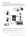
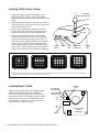
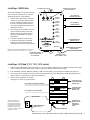
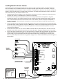
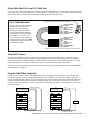
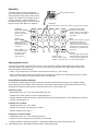
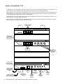
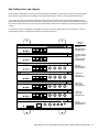
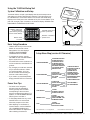
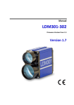
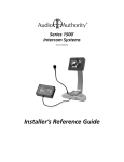
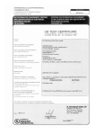
Series 1500
Intercom Systems
™
Installer’s Reference Guide
For Firmware Version 4.0
Contents
Introducing Series 1500™ Intercom Systems . . . . . . . . . . . . 3
Series 1500 System Components . . . . . . . . . . . . . . . . . . 3
2x4 Audio Installation . . . . . . . . . . . . . . . . . . . . . . . . . 4
2x4 Audio/Video Installation . . . . . . . . . . . . . . . . . . . . . 5
Installing Model 1500AH . . . . . . . . . . . . . . . . . . . . . . . 6
Installing a 1509SD Hub . . . . . . . . . . . . . . . . . . . . . . . 7
Installing a 1510 Hub (1511, 1512, 1513 similar) . . . . . . . . . . 7
Installing Model 1520 Lane Stations . . . . . . . . . . . . . . . . . 8
Using Third Party Traffic Sensors . . . . . . . . . . . . . . . . . . 9
Program Audio/Video Connection . . . . . . . . . . . . . . . . . . 9
Operation . . . . . . . . . . . . . . . . . . . . . . . . . . . . . . 10
Audio or AV Hub Model 1510 . . . . . . . . . . . . . . . . . . . . 12
Hub Configurations and Capacity . . . . . . . . . . . . . . . . . . 13
Common Issues . . . . . . . . . . . . . . . . . . . . . . . . . . . 14
Testing the Installation . . . . . . . . . . . . . . . . . . . . . . . . 14
Troubleshooting Tips . . . . . . . . . . . . . . . . . . . . . . . . 14
Using the 1550 Field Setup Tool . . . . . . . . . . . . . . . . . . . 15
System Calibration and Setup . . . . . . . . . . . . . . . . . . . . 15
Power User Tips . . . . . . . . . . . . . . . . . . . . . . . . . . . 15
Setup Menu Map . . . . . . . . . . . . . . . . . . . . . . . . . . 15
Definitions . . . . . . . . . . . . . . . . . . . . . . . . . . . . . . 16
1550 Configuration Example . . . . . . . . . . . . . . . . . . . . 17
SD Card Notes . . . . . . . . . . . . . . . . . . . . . . . . . . . 18
Firmware Upgrade Instructions . . . . . . . . . . . . . . . . . . . 18
WARNINGS
• Read these instructions before installing or using this product.
• To reduce the risk of fire or electric shock, do not expose this unit to rain or moisture.
• This product must be installed by qualified personnel.
• Do not open the cover—there are no user-serviceable parts inside.
• Do not expose this unit to excessive heat.
• Install only in dry, indoor locations.
• Clean the unit only with a dry or slightly dampened soft cloth.
LIABILITY STATEMENT
Every effort has been made to ensure that our products are free of defects. Audio Authority cannot be held liable for the use
of this hardware or any direct or indirect consequential damages arising from its use. It is the responsibility of the user of the
hardware to check that it is suitable for his/her requirements and that it is installed correctly. All rights are reserved. No parts
of this manual may be reproduced or transmitted by any form or means electronic or mechanical, including photocopying,
recording or by any information storage or retrieval system without the written consent of the publisher.
Audio Authority reserves the right to revise any of its hardware and software following its policy to modify and/or improve its
products where necessary or desirable.
Audio Authority and the Double-A Symbol are registered trademarks of Audio Authority Corp. Copyright June, 2007. All third
party trademarks and copyrights are recognized.
2
Audio Authority® Series 1500 Installer’s Reference Guide • Firmware Version 4.0
Installer’s Reference Guide
Introducing Series 1500™ Intercom Systems
Series 1500™ Intercom systems enable clear two-way
communications in retail service businesses. Two-way video is
integrated with high-performance audio to provide a complete
intercommunication solution over a single Category 5e or 6
UTP cable. The versatile Model 1500A or 1500AH Counter
Station can access up to 16 lanes. Model 1520 Lane Stations
can be connected directly to a Counter Station in a one-on-one
system, or multiple Counter Stations and Lane Stations can be
networked using an Audio Authority Intercom hub.
Model 1509SD audio hub is perfect for two-on-four audio
systems, while 1510 series modular hubs can support up to 8
Counter Stations on 16 lanes. A 1510 series hub is required for
multi-lane video systems (see examples). One-way or two-way
video is easily added by installing a Model 1501A (inbound
only) or 1502A (two-way) Counter Video Add-on.
Special Tools and Supplies
• Cat 5 network cable tester
• RJ-45 plug crimping tool (Audio
Authority recommends EZ-RJ Pro
crimp tool)
• Category 5e or 6 UTP cable
and RJ-45 terminations (Audio
Authority recommends EZ-RJ-45
connectors)
• 18mm flare nut wrench for
gooseneck mic installation
• Model 1550 Field Setup LCD
Display Tool
Series 1500 System Components
Counter Station (audio)
Counter video add-on
Counter video add-on
Wall mount counter video add-on
Wall mount counter video add-on
2-way video adapter
2-on-4 audio hub
4-on-4 audio/video hub
4-on-8 audio/video hub
8-on-12 audio/video hub
8-on-16 audio/video hub
4-counter plug-in card
4-lane plug-in card
System plug-in card
Lane Station
1500A
1501A
1502A
1501W
1502W
1504
1509SD
1510*
1511*
1512*
1513*
1515
1516
1517SD
1520
Complete A/V Station
Customer video add-on
Customer video add-on
Telephone Interface
Surface-mount handset
Flush-mount handset
Wireless headset
Traffic sensor Headset switch
Field setup LCD
Universal power supply
5 Amp power supply
Gooseneck microphone
External microphone kit
External 3” speaker
1522
1523
1524
1533
1540
1541
1542
1547
1548
1550
571-013
805-028
631-026
631-029
631-030
*See page 11 for hub configurations
Audio Authority® Series 1500 Installer’s Reference Guide • 800-322-8346 • 859-233-4599
3
1x1 Installation
The simplest system configuration involves only one counter station connected directly to one lane station (no hub).
This configuration can be audio-only or audio/video. Run a length of Cat 5 cable from the counter location to the lane
location; the cable can be up to 1,000 feet long. See “Installing Components” for detailed instructions.
POWER
AUDIO/VIDEO
COUNTER STATION
MIC
SPEAKER
LANE STATION
LOCATED IN
DRIVE UP UNIT
CALL BUTTON
TRAFFIC SENSING
REMOTE CONTROL RELAY
ARMORED HANDSET
MODEL 1500A
MODEL
1520
HEADSET
Note: In systems without a hub,
there is no way to upgrade
firmware or access some features
of the 1550 setup tool. A hub
can be temporarily connected to
program all functions using a 1550.
POWER
2x4 Audio Installation
The Model 1509SD Audio Hub allows one or two Model 1500A Audio Counter Stations to serve up to four 1520 Lane
Stations. 1509SD Hub configurations must be audio-only. Run a length of Cat 5 cable from each Counter Station to
the Hub. Run a length of Cat 5 cable from the Hub to each Lane Station. The total cable length from Counter Station to
Lane Station can be up to 1,000 feet. See “Installing Components” for detailed instructions.
POWER
MIC
SPEAKER
CALL BUTTON
LANE STATION
LOCATED IN
DRIVE UP UNIT
TRAFFIC SENSING
REMOTE CONTROL RELAY
POWER
AUDIO
COUNTER
STATION
ARMORED HANDSET
MODEL
1520
MODEL 1500A
HEADSET
POWER
AUDIO HUB
MODEL 1509SD
AUDIO
COUNTER
STATION
MODEL 1500A
HEADSET
POWER
4
Audio Authority® Series 1500 Installer’s Reference Guide • Firmware Version 4.0
2x4 Audio/Video Installation
The Audio/Video Hub configurations allow from one to as many as eight Counter Stations to serve up to 16 Lane
Stations. These configurations (1510, 1511, 1512 and 1513) may be audio-only or audio/video. Run a length of
Cat 5 cable from each Counter Station to the Hub. Run a length of Cat 5 cable from the Hub to each Lane Station. The
total cable length from Counter Station to Lane Station can be up to 1,000 feet. See “Installing Components” for detailed
instructions.
MIC
SPEAKER
CALL BUTTON
POWER
CUSTOMER
VIDEO ADD-ON
LANE STATION
LOCATED IN
DRIVE UP UNIT
TRAFFIC SENSING
REMOTE CONTROL RELAY
MODEL 1523
ARMORED HANDSET
MODEL 1502A
POWER
MODEL
1520
A/V
COUNTER
STATION
MODEL 1500A
HEADSET
MODEL 1502A
A/V
COUNTER
STATION
MODEL 1500A
HEADSET
POWER
POWER
SINGLE CAT 5 CABLE
COAX (RG59)
FROM HUB CAMERA OUTPUTS
TO SECURITY VIDEO RECORDER
FROM DVD or PC* AUDIO/VIDEO
TO HUB PROGRAM INPUTS
SURVEILLANCE CAMERA OUTPUT
TO HUB WIDEANGLE CAMERA INPUT
AUDIO OR OTHER WIRE
Illustration: Two Counter Stations serve Four Lane Stations. Counter Stations and Lane Stations may have video
capability, or audio-only. One Lane Station is shown with a Model 1523 Video Add-On; alternatively, any 1520 may be
connected to existing camera and video display.
If desired, any 1520 could be replaced by a 1522 Customer Video Station, which has all the capability and connections
of a 1520 plus a camera, video display and call button mounted in one enclosure.
* PC video output signals may need to be modified for viewing on intercom video displays. See page 9 for details.
Audio Authority® Series 1500 Installer’s Reference Guide • 800-322-8346 • 859-233-4599
5
Installing 1500A Counter Stations
GOOSENECK
MICROPHONE
1. Unpack each Model 1500A Counter Station and, if
applicable, install a 1501A or 1502A Video Display.
Plug the Cat 5 video cable into the matching port on the
1500A.
BOOT
2. Attach the field-replaceable microphone, tightening the
nut securely with a 18mm flare nut wrench, and tuck its
rubber boot firmly into place.
18MM NUT
3. Plug the Cat 5 cable from the hub into the Hub port
of each 1500A and connect the power supply to the
Power jack. See page 9 for Cat 5 cable fabrication.
4. Install the desired keyboard inlays into the Model
1500A. On initial power-up, the hub sets the default
key layout automatically according to the number of
connected Counter and Lane Stations (see examples
below). You can choose to color-code by the carrier
color or label the keys numerically. Place blank, black
chips in all non-active positions. Save the unused key
chips on the premises for future changes or expansion.
Single Lane (1x1) Default
1509 or 1510 Default
MIC PORT
POWER
SUPPLY
HEADSET
1511 Default
HUB
PORT
VIDEO DISPLAY
CONNECTION
HANDSET
PORT
1512 Default
Illustration: Default key assignmens for various lane configurations. Key assignments may be changed from default by connecting a 1550 Field Setup
Tool and accessing “teller parameters” and “key assignment.” See page. 15.
Installing Model 1500AH
1500AH Counter Stations ship with a handset cradle
attached. Install them the same as a 1500A but
connect the included handset to the handset port on
the underside of the Counter Station as shown. Adjust
handset volume using the 1550 field setup tool, then,
if more adjustment is desired, use the two knobs on
the bottom of the 1500AH as shown.
RX = Inbound
Handset Audio
TX = Outbound
Handset Audio
CRADLE
6
HANDSET
PORT
Audio Authority® Series 1500 Installer’s Reference Guide • Firmware Version 4.0
1500AH COUNTER
STATION
(UNDERSIDE)
Installing a 1509SD Hub
PROGRAM AUDIO INPUTS
The Model 1509SD is a compact audio hub
with a maximum capacity of two Counter
Stations serving four Lane Stations.
1. Position and install the Hub under the
counter or in a secure indoor location
such as a telephone closet. Ground
the hub to a nearby electrical device
cover using the green grounding wire
attached to the hub.
PROGRAM AUDIO VOLUME
LEVEL ADJUSTMENT
CAT 5 CABLE TO
COUNTER STATION #1
LEVEL
COUNTER
STATION 1
PROGRAM AUDIO
COUNTER
STATION 2
CAT 5 CABLE TO
LANE STATION #1
LANE
STATION 1
LANE
STATION 2
2. Run a length of Cat 5 cable from each
counter and lane station to the hub.
Observe the wiring guide on page 9,
and use a cable tester to verify the
terminations.
LANE
STATION 3
LANE
STATION 4
3. If desired, connect an audio source
to Program Audio jacks, and adjust
volume level during system testing.
See page 9 for more on program audio.
1 AMP POWER SUPPLY
(MODEL 571-013)
12 VOLT
DC POWER
SD CARD
Illustration: Shown is Model 1509SD Audio Intercom Hub.
Minimum connections are shown for a 1 on 1 system.
SD CARD FOR STORING
SYSTEM SETTINGS AND
FIELD UPGRADES
DIAGNOSTICS
GROUND WIRE TO ELECTRICAL
DEVICE COVER
DIAGNOSTICS PORT
(NOT CURRENTLY USED)
Installing a 1510 Hub (1511, 1512, 1513 similar)
1. Position and install the Hub under the counter or in a secure indoor location such as a telephone closet. Ground the
hub to a nearby electrical device cover using the green grounding wire attached to the hub.
2. If the installation requires additional capacity, install a Counter Card or Lane Card(s) as needed (see page 13).
3. Run a length of Cat 5 cable from each counter and lane station to the hub. Observe the cable fabrication guide on
page 9, and use a cable tester to verify the terminations.
4. Connect other equipment as needed.
See page 9 for more on program audio.
CAT 5 CABLE TO COUNTER STATION #1
FOUR-UNIT COUNTER STATION CARD
(MODEL 1515)
CAT 5 CABLE TO LANE STATION #1
FOUR-UNIT LANE
STATION CARD
(MODEL 1516)
GROUND WIRE
Illustration: Model 1510,
the minimum capacity A/V
Hub configuration. Minimum
connections for Audio/Video
Hubs are shown. For more
configurations, system card
functions, and other connections,
see page 12 and 13.
SYSTEM CARD
(MODEL 1517SD)
SEE PAGE 12
FOR INSTRUCTIONS
1 AMP POWER SUPPLY
(MODEL 571-013)
POWER CONNECTION
Audio Authority® Series 1500 Installer’s Reference Guide • 800-322-8346 • 859-233-4599
7
Installing Model 1520 Lane Stations
Lane Stations may be placed at the customer end of a drive-up or walk-up intercom system. The Model 1520 is the
basic Lane Station unit for installations where the microphone, speaker (plus video screen and camera, if used) are
mounted separately. The Model 1522 is a Video Lane Station, including all of the features of the 1520 plus microphone,
speaker, camera and video screen mounted inside one enclosure. The Model 1523 Video Add-on must be used with a
1520, and contains only the camera and video screen.
1. Install the Model 1520 Lane Station in each deal drawer or pneumatic unit on the customer end, using the screws
provided. If AC power is not available at the customer end, see Step 5.
2. Install the lane microphones and speakers if they are not already installed. Mount the speakers in the grilles
provided in the drive-up units. Peel the backing from the microphone shrouds and adhere them directly centered
over a 1/8” hole drilled in the faces of the customer units. At each station, place the microphone and speaker as
far apart as practical, while centering the microphone to receive customer speech. Install Teller Call push-button
switches, if needed.
3. Connect the Microphones, Speakers and Teller Call switches to the 1520 terminal blocks. Strip all wires 1/4” long.
If pneumatic blower muting is desired, connect the DRY blower contacts to the corresponding points on the terminal
blocks, using small (22-18 AWG) wire. If traffic sensing devices or remote-controlled security doors are in use,
connect them as indicated.
4. At each lane where video is in use, connect a Model 1523 Video Add-on to the Video port on the 1520 or connect
standard 75-ohm NTSC cameras and monitors to the 1520 video jacks. Plug power supplies into the Power jacks.
5. Plug the lane power supplies into a source of 100-240 volts AC. An adapter cable is provided with the 1520 to allow
power to be drawn from a terminal block in a pneumatic unit. If AC power is not available on the customer end,
a power supply may be located indoors and its output leads extended using a suitable gauge of wire as shown
below. To power multiple lane units from a single power supply source, contact Audio Authority Technical Support at
800‑322‑8346.
MICROPHONE
SPEAKER
CALL BUTTON
3RD PARTY
Traffic
Sensor
POWER
TRAFFIC SENSE
1 +
2 –
MICROPHONE
3 +
4 –
SPEAKER
MONITOR
5 CALL BUTTON
BLOWER
6 TRAFFIC SENSE
7 BLOWER
8 COMMON
9
10
ANY DEVICE TO BE
+
CONTROLLED BY RELAY –
HANDSET
Recommended AWG
Maximum
Distance
40 ft
60 ft
100 ft
8
Gauge
18
16
14
1547 cable
may be
extended
using Cat 5
Model 1547
Traffic
Sensor
Audio Authority® Series 1500 Installer’s Reference Guide • Firmware Version 4.0
CAMERA
N.O. CONTACTS
1523
VIDEO
MODULE
HUB
CABLE ADJUST
(SEE INSTRUCTIONS)
1547 connects to port
behind knock out.
1 - WHITE/GREEN
2 - WHITE/ORANGE
3 - BLUE
4 - WHITE/BLUE
5 - ORANGE
6 - GREEN
Using Cable Adjust for Long Cat 5 Cable Runs
For a Cat 5 cable run with total length over 100 feet, use the following guidelines: Set cable length on the receiving end
of the cable run in increments of 100 feet (1 = 100 to 199 feet, 2 = 200 to 299, etc.). For 1-way video set only the length
1 - GREEN
control on the 1501. For 2-way video set the length controls on both the 1520 and 1502. 2 - ORANGE
3 - WHITE/BLUE
4 - BLUE
5 - WHITE/ORANGE
6 - WHITE/GREEN
RJ-45 plug with pins facing up and clip facing away.
Cat 5 Cable Fabrication
Cat 5e or Cat 6 is UTP (Unshielded
Twisted Pair) cable that can be
used to connect Series 1500
components. Terminate the ends
of each Cat 5e/6 cable with RJ-45
modular plugs using the EIA 568B
pinout (paired 1-2, 3-6, 4-5, and
7-8). Pre-made network cables may
also be used for shorter runs. TEST
all cables (including pre-made) with
a network cable tester.
1
2
3
4
5
6
7
8
Cat 5e/6
1
2
3
4
5
6
7
8
RJ-45 Plug
Pin 1
WHITE / ORANGE
ORANGE
WHITE / GREEN
BLUE
WHITE / BLUE
GREEN
WHITE / BROWN
BROWN
WHITE / ORANGE
ORANGE
WHITE / GREEN
BLUE
WHITE / BLUE
GREEN
WHITE / BROWN
BROWN
Clip is pointed
away from you.
CABLES ARE WIRED THE SAME ON BOTH ENDS (NOT CROSSED OVER).
Using Traffic Sensors
The 1520 Lane Station provides a connection for Audio Authority’s Model 1547 traffic sensor on the bottom edge of
the case (see illustration on page 8). When a vehicle triggers the 1547, the Counter Station generates a call tone for
the corresponding lane to alert the operator. The call tone for the traffic sensor can be a distinct ring tone from the call
button at the same lane. To extend a traffic sensor, use an in-line coupler and a length of Cat 5 cable.
Alternatively, a third party traffic sensor may be used by connecting it to the TRAFFIC SENSE terminal and COMMON
terminal as shown on page 8.
Program Audio/Video Connection
If audio or video program content will be playing at the customer positions when lane stations are on HOLD or idle,
plug the source player or PC into the Program Input ports on the 1509SD or 1510 series hub. Program audio level
may be manually adjusted at the hub. Any lane’s program audio may be turned off during idle periods (still heard while
on HOLD) using the 1550 Program Audio Abate setting (see page 16). If the program video source is a PC, either a
composite video card or external converter is required. Audio Authority Model 1361 is an ideal adapter to convert VGA
to composite video.
DVD PLAYER
(COMPOSITE VIDEO)
COMPOSITE VIDEO
PC
(VGA OUTPUT)
VGA
AUDIO
LEVEL
CONTROL
1361
AUDIO
COMPOSITE VIDEO
Audio Authority® Series 1500 Installer’s Reference Guide • 800-322-8346 • 859-233-4599
9
Operation
The Series 1500 Intercom is operated via
touch-sensitive keys on Model 1500A Counter
Station keypads, shown below. Tasks such as
answering a customer call, ending a call, and
putting a customer on HOLD are shown on
the Operator Guide (page 11) which should be
kept near the Counter Station for reference.
Counter Station Keypad.
LANE KEYS
Lane 1 and Lane 2, represented by colors, are located here by default.
CAMERA UP
AND DOWN
If video is installed,
aims the lane camera
higher or lower.
VOLUME UP AND DOWN
Customer’s voice becomes
louder or softer in Counter Station
speaker or earpiece of headset
and handset.
MIRROR
When two-way
video is installed, use
MIRROR to aim the
Counter Station camera
on operator.
HOLD
Place a Lane on HOLD. If program
audio/video is installed, the
customer hears music or other
messages. Touch the Lane Key to
resume contact. Touch and hold
the HOLD key to operate a relay
(see below).
SETUP
Choose ringtones and
ring volume. Choose
handset/headset
volume (page 11).
PRIVACY
The privacy key is used to switch
from the speaker and gooseneck
PRIVACY LIGHT
mic to the wireless headset. It is
Comes on when wireless
headset or handset is active. not used with the handset.
Operating Remote Devices
The 1520 can be wired to operate a latch or door in a remote location via the 1500A keypad (see page 8 for relay
connection details). The system can be set up (using the 1550) to be operated in two different ways; consult your
technical support provider for details.
• Option 1: Any time the lane is selected the remote device is active (e.g. a door opens).
• Option 2: When a lane is active, the operator touches and holds the HOLD key to activate the device (e.g. hold the
door open). The HOLD key operates normally when touched briefly.
Using a Wireless Headset or Handset
The 1500A and 1500AH switches between the built-in speaker and gooseneck microphone, the 1500AH handset,
and an optional wireless headset. Some examples of using these communication methods are listed below. Always
deactivate the wireless headset between customer interactions to increase battery life.
Answering a Call
• Speaker/gooseneck mic: Touch the rapidly flashing lane key.
• Handset: Pick up the handset. Touch the rapidly flashing key.
• Wireless headset: Activate the headset, touch PRIVACY and select the flashing lane. If the headset is the preferred
method, leave PRIVACY on.
Putting a Call on HOLD
• Speaker/gooseneck mic: Touch HOLD.
• Handset: Touch HOLD, then hang up the handset.
• Wireless headset: Touch HOLD.
Picking Up a Call from HOLD
• Speaker/gooseneck mic: Touch the blinking lane key.
• Handset: Touch the blinking lane key and pick up the handset.
• Wireless headset: If PRIVACY is already on, activate the headset and select the blinking lane key.
10
Audio Authority® Series 1500 Installer’s Reference Guide • Firmware Version 4.0
OPERATOR GUIDE
Model 1500A Intercom
Counter Station
Operation Tips
• Speak naturally into the microphone at a distance of about two inches
• Touch keys with the pad of your finger
• Press MIRROR to view yourself (2-way video only) – to aim camera, adjust display tilt
Lane Key Indicators
RED (flashing rapidly)
GREEN
RED
GREEN (blinking slowly)
RED (blinking slowly)
GREEN (flashing rapidly)
=
=
=
=
=
=
Customer CALLING for service
Customer in 2-WAY contact with your counter station
Customer in 2-WAY contact with another counter station
Customer placed on HOLD from your counter station
Customer placed on HOLD from another counter station
Monitoring transaction on another counter station (Master Teller)
Counter Station
• To contact a customer calling
• To place a customer on HOLD
• To contact a customer on hold
• To end contact with customer
• To cancel hold and end contact
• To talk over a customer
• To adjust incoming volume
• To enter/exit PRIVACY (headset) mode
• To activate remote relay
Touch LANE key
Touch the HOLD key
Touch the LANE key
Touch the active LANE key
Touch the LANE key twice
Touch and hold the active LANE key
Touch VOLUME UP or VOLUME DOWN key
Touch the PRIVACY key
See installer or administrator for instructions
Adjust Counter Station Handset Volume (1500AH)
• In SETUP MODE, touch PRIVACY and press VOLUME UP or DOWN
• If further handset transmit or receive volume adjustment is needed, contact your technical support provider
Wireless Headset
• To use a wireless headset, touch PRIVACY, activate the headset, and select the flashing lane key
• If the headset is the preferred method, leave privacy on
• To increase headset battery life, deactivate the headset between customer interactions
Handset
• To answer a call, pick up the handset and touch the rapidly flashing lane key
• To place a customer on hold, touch HOLD
• To speak to a customer on hold, pick up the handset and touch the lane key
Counter Station Video
• To adjust outside camera on selected lane
• To view yourself (to aim camera)
• To view outgoing video program
• To pause lane camera scrolling
• To view next lane camera
• To view previous lane camera
Touch CAMERA UP or CAMERA DOWN key
Touch MIRROR key (30 second time-out)
Hold MIRROR key 3 seconds (no lane selected)
Touch HOLD key (no lane selected)
Touch CAMERA UP key (no lane selected)
Touch CAMERA DOWN key (no lane selected)
Adjust Ringtones and Ringer Volume
• Touch and hold the SETUP key until lights next to CAMERA and VOLUME keys blink
• Touch CAMERA UP and DOWN to select one of 16 ringtones
• Touch VOLUME UP and DOWN to set ringer volume
2048 Mercer Road, Lexington, KY 40511 • 800-322-8346 • 859-233-4599
Fax: 859-233-4510 • www audioauthority com • support@audioauthority com
752-487
9/10
Audio Authority® Series 1500 Installer’s Reference Guide • 800-322-8346 • 859-233-4599
11
Audio or AV Hub Model 1510
• The Model 1510 is an audio/video Hub with a capacity of up to four Counter Stations serving four Lane Stations. The
Hub’s capacity can be expanded in the field by adding Counter and/or Lane cards (see page 13).
• System settings can be stored on a standard SD card for security or replication purposes. Firmware upgrades can be
downloaded from the Audio Authority website and performed using the SD card when necessary. These operations
require a Model 1550 Field Setup Tool and a Counter Station.
• Composite video and stereo analog audio inputs allow multimedia source devices to play advertising content on any
lane whenever it is idle. See page 9 for details.
• Direct outputs from wide angle camera (dedicated security camera) and/or lane cameras for surveillance recording.
Video is output continuously from each camera connected.
CONNECT COUNTER
STATIONS HERE
1515
1
ACTIVE
2 3 4
1
1
ACTIVE
2 3 4
1
COUNTER
CARD 1
COUNTER STATION
4
2
3
LIGHTS INDICATE
CONNECTIVITY
AND VOICE/VIDEO
COMMUNICATION
1516
LANE STATION
2
3
4
1
SECURITY VIDEO OUTPUT
2
3
4
LANE
CARD 1
CONNECT LANE
STATIONS HERE
CONNECT TO
SECURITY
VIDEO
VIDEO
RECORDER
RECORDER
OR
OR MONITOR
MONITOR
FLASHING LIGHT
INDICATES NORMAL
HUB OPERATION
1517
POWER
MEMORY
PROGRAM INPUT
DIAGNOSTICS WIDEVIEW CAMERA
INPUT
OUTPUT VIDEO
AUDIO
LEVEL
SYSTEM
CARD
SD CARD
CONNECT POWER
SUPPLY TOWARD
REAR UNDER THE
CABINET
CONNECT GROUND
WIRE TO ELECTRICAL
DEVICE COVER SCREW
12
NOT
CURRENTLY
USED
SD CARD SLOT
FOR BACKUP AND
UPGRADES
CONNECT
TO VIDEO
RECORDER OR
MONITOR
CONNECT
DEDICATED
SECURITY
CAMERA
Audio Authority® Series 1500 Installer’s Reference Guide • Firmware Version 4.0
CONNECT
AUDIO OR AV
SOURCE
ADJUST
PROGRAM
AUDIO
VOLUME
Hub Configurations and Capacity
Shown below is the Model 1513 Hub, a maximum capacity configuration; all Counter and Lane Card slots are filled.
Several other configurations are available; contact Audio Authority® for details, or visit www.audioauthority.com.
To increase Counter or Lane Station capacity, remove power from the Hub. Remove the blank faceplate from the
appropriate card slot(s) and insert the new cards carefully, making sure the connections are firmly seated. Insert the
two screws to secure the card, and connect new Lane Stations and/or Counter Stations. Connect power and test the
system.
An alternate maximum configuration is possible, in which four Counter Stations serve 20 Lane Stations. If a 4x20
configuration is desired, contact Audio Authority for special instructions.
CARD SLOT
OPTIONS
1515
1
ACTIVE
2 3 4
1
COUNTER
CARD 1
COUNTER STATION
2
3
4
FIRST 1515
REQUIRED FOR ALL
CONFIGURATIONS
1515
5
ACTIVE
6 7 8
5
1516
1
ACTIVE
2 3 4
1
1516
5
ACTIVE
6 7 8
5
LANE STATION
6
7
8
5
SECURITY VIDEO OUTPUT
6
7
8
LANE
CARD 2
1516
ACTIVE
9 10 11 12
9
LANE STATION
10
11
12
9
SECURITY VIDEO OUTPUT
10
11
12
LANE
CARD 3
1516
ACTIVE
13 14 15 16
13
LANE STATION
14
15
16
13
SECURITY VIDEO OUTPUT
14
15
16
LANE
CARD 4
1517
COUNTER
CARD 2
COUNTER STATION
6
7
8
LANE STATION
2
3
4
1
SECURITY VIDEO OUTPUT
2
3
4
SECOND 1515 FOR 8
COUNTER STATIONS
– OR –
FIFTH 1516 IN 4X20
CONFIGURATIONS
LANE
CARD 1
FIRST 1516
REQUIRED FOR ALL
CONFIGURATIONS
POWER
MEMORY
PROGRAM INPUT
DIAGNOSTICS WIDEVIEW CAMERA
INPUT
OUTPUT VIDEO
AUDIO
LEVEL
SECOND 1516
FOR 8 LANE
CONFIGURATIONS
THIRD 1516
FOR 12 LANE
CONFIGURATIONS
FOURTH 1516
FOR 16 LANE
CONFIGURATIONS
SYSTEM
CARD
1517SD
(REQUIRED FOR ALL
CONFIGURATIONS)
Audio Authority® Series 1500 Installer’s Reference Guide • 800-322-8346 • 859-233-4599
13
Testing the Installation
Check the following locations for successful power-up and connectivity, indicated as follows:
• 1500A Counter Station: All LEDs become dark until keys are pressed
• 1509SD Audio Hub: flashing green Power LED, rapidly flashing counter station and lane station LEDs
• 1517SD Hub system card: flashing green LED, rapidly flashing counter station and lane station LEDs
• 1520 Lane Station: rapidly flashing Power LED
Check system operation by selecting each lane and speaking with an assistant at the customer position. Adjust Lane
Microphone and Speaker gains using the Model 1550 Field Setup LCD.
Troubleshooting Tips
• Always test Cat 5 cables with a professional Network Cable Tester – even pre-made cables (see page 9)
• Try connecting a Counter Station directly to a Lane Station to rule out faulty system components
• In case of unexpected performance, restore system defaults to rule out incorrect system parameters
Common Issues
Acoustical Coupling
• Increase separation of lane microphone and speaker
• Isolate lane microphone and speaker with sounddamping barrier (i.e. foam rubber)
• Mount lane speaker and microphone on separate
surfaces or adjust their mounting angles
• Adjust inbound, outbound or open loop gain levels
Counter Station Lights Remain in ‘Burn in’ Pattern
• Check Cat 5 cable - consistently use EIA 568B
standard cable termination (see page 9)
• Ensure Counter Station is connected to the correct
hub port
The Deal Drawer Doesn’t Sound Right
• Fill hollow cavities in the deal drawer with foam
rubber sheets or blocks
• Do not rest Counter Station directly on top surface of
deal drawer
Repeating Pops in Audio
• Check Cat 5 cables - consistently use EIA 568B
standard cable termination (see page 9)
14
No Inbound / Outbound Video or Poor Video
Quality
• Check Cat 5 cables - consistently use EIA 568B
standard cable termination (see page 9)
• Eliminate long coaxial cable runs between cameras/
displays and Lane Station.
Lane Keys Don’t Respond
• Keys not assigned to Counter Station – reassign keys
or restore factory defaults in configuration menu
Lane Microphone Doesn’t Work
• Microphone must be electret condenser type
• Check microphone polarity
Wind Noise
• Can often be eliminated by putting a small plug of
3M Scotchbrite™ in the microphone opening. The
Audio Authority lane microphone has a special foam
surround; for optimum results, use Audio Authority
microphones.
Audio Authority® Series 1500 Installer’s Reference Guide • Firmware Version 4.0
Using the 1550 Field Setup Tool
SERIES
1
EQUIP 500
ME
CALIBRNT
AT
PLATF ION
ORM
System Calibration and Setup
The Model 1550 is a liquid crystal display that shows the setup menus
and settings for Series 1500 Intercom Systems. The entire system can
be calibrated from one Counter Station. Connect the 1550 Field Setup
Display to the RJ45 jack on the underside of any live Counter Station. (The
jack is at an angle.) Upon connection, the 1550 will display “SERIES 1500
EQUIPMENT CALIBRATION PLATFORM”.
CAMERA = Select next
or previous Station
(after selecting a single
Lane or Counter Station)
1
2
3
4
5
6
7
8
VOLUME = Move menu
cursor up and down
9 10 11 12
SETUP = Enter
or Confirm
PRIVACY = Go Back to
previous menu
13 14 15 16
Basic Setup Procedure
1500A COUNTER STATION (UNDERSIDE)
• Hold the SETUP key on the Counter
Station for one second to enter
Setup Mode. The 1550 displays:
“SERIES 1500 EQUIPMENT
CALIBRATION PLATFORM”.
Setup Menu Map (version 4.0 firmware)
• To navigate the menus, use the
VOLUME UP and VOLUME DOWN
keys to move the cursor.
• Touch SETUP to enter a submenu or
confirm a selection, and PRIVACY to
go back.
• Any changes you make are recorded
as you exit each submenu. When
you exit Setup Mode, you must
choose to either save all changes
and exit or exit without saving.
1:SYSTEM PARAMETERS
Power User Tips
• For faster menu navigation,
submenus may be selected by
touching the key that is lit RED
corresponding to the menu item
(see the numbered keys above). For
instance, to enter BLOWER MOTOR
DELAY, press 1 and then 1.
• To Exit Setup Mode from any menu,
hold SETUP for one second and
follow the prompts on the 1550.
1:BLOWER MOTOR DELAY
2:POWER SAVE DELAY **
3:SUPERVISOR TELLER *
4:LN MIRROR DISABLE **
5:TRAFFIC SENSOR TONE
6:BACKGRND THRESHOLD
7:ALLOW VIDEO SCROLL
8:MASTER TELLER
2:LANE PARAMETERS
1:SINGLE LANE
2:AUTO-SELECT 1 LANE
3:GROUP OF LANES
4:ALL LANES
5:CANCEL
3:TELLER PARAMETERS *
1:THIS TELLER
2:SINGLE TELLER
3:GROUP OF TELLERS
4:ALL TELLERS
5:CANCEL
4:SET DEFAULTS
1:CANCEL
2:PHARMACY DEFAULTS
3:FINANCIAL DEFAULTS
5:MEMORY CARD *
1:CANCEL
2:WRITE TO MEM. CARD
3:READ FROM MEM. CARD
4:FIRMWARE UPGRADE***
6:EXIT
1:CANCEL
2:EXIT AND SAVE
3:EXIT WITHOUT SAVING
• If you need to re-enter Setup Mode,
simply press SETUP for one second.
• After adjusting a Lane Station or
Counter Station, use the CAMERA
UP or CAMERA DOWN keys to
select other stations for adjustment
without leaving the submenu.
RECESSED
JACK
(ANGLED)
CAT 5E/6
* Not available for 1 on 1 configurations
1:INBOUND VOLUME LVL
2:OUTBOUND VOLUME LVL
3:OPEN LOOP GAIN
4:HANDSET MIC LVL
5:HANDSET SPKR LVL
6:RINGTONE OVERRIDE *
7:HALF DUPLEX ONLY
8:PROGRAM AUDIO ABATE *
9:RELAY OPERATION
10:SWAP CAMERA UP/DN
1:KEY ASSIGNMENT **
2:ALLOW HANDSFREE
*Not available for 1 on 1 configurations
** Not available for 1509 Audio Hub
*** Not available for 1560
** Not available for 1509 Audio Hub
Audio Authority® Series 1500 Installer’s Reference Guide • 800-322-8346 • 859-233-4599
15
Definitions
16
AUTO-SELECT 1 LANE
Allows installer to configure lane audio settings using live audio from the lane. Useful
for adjusting inbound and outbound audio levels.
ALLOW HANDSFREE
Allow communication using speaker and gooseneck microphone.
ALLOW VIDEO SCROLL
Inactive Counter Stations view all available cameras in sequence; when video scroll
is disabled, inactive Counter Stations see only the wideview camera (if installed).
BACKGRND THRESHOLD
Adjustment for level of background audio rejected by Counter Station microphone.
0 = no rejection.
BLOWER MOTOR DELAY
If enabled, the period between disengagement of blower and microphone audio unmute.
FIRMWARE UPGRADE
This menu allows the firmware of system components to be upgraded.
HANDSET MIC LVL
Inbound handset volume level adjustment.
HANDSET SPKR LVL
Outbound handset volume level adjustment.
HALF DUPLEX ONLY
Enables ‘push-to-talk’ operation.
INBOUND VOLUME LVL
Inbound volume level adjustment.
KEY ASSIGNMENT
This menu enables lane selection keys to be redefined in any configuration desired.
First select the lane number to be assigned using the VOLUME keys. Then touch the
key to be assigned to that lane. If the desired key is already assigned, touch it twice.
For 20 lane systems use “Page Mode”. Page Mode allows the user to flip between
two “pages” of keys. The first page contains lane 1-10, the second 11-20. To enter or
exit Page Mode, touch the HOLD key while in KEY ASSIGNMENT.
LANE MIRROR DISABLE
OFF = idle Lane Stations display their own camera output.
ON = idle Lane Stations DO NOT display their own camera output.
MASTER TELLER
Enables one Counter Station to monitor conversations conducted on all other Counter
Stations.
OUTBOUND VOLUME LVL
Outbound volume level adjustment.
OPEN LOOP GAIN
Adjustment for adapting to different acoustic environments. Lower this setting for
Lane Station acoustical environments with too much microphone and speaker
coupling. Increase this setting to hear more of the customer while operator is talking.
PGM AUDIO ABATE
ON = Program Audio heard ONLY when lane is on hold.
OFF = Program Audio heard when lane is idle OR on hold.
PHARMACY SETTINGS
See the Model 1533 Telephone Intercom Interface Manual for details.
POWER SAVE DELAY
If enabled, the length of time the system must be idle before entering Power Save
(LCD sleep). This feature only applies to lane montiors, not Counter Sation monitors.
READ FROM MEM. CARD
System settings are restored from hub memory card.
RELAY OPERATION
Allows configuration of Lane Station relay contacts (Model 1520 terminal block pos.
9 & 10). The contacts can be set to close using the HOLD key, or while the lane is
selected. (See Operator Card l for HOLD key operation details.)
RINGTONE OVERRIDE
Press a key to select a unique ringtone for the selected Lane Station(s).
1 = no override (plays the ringtone set by each Counter Station).
All other keys represent unique ring tones which override any Counter Station
settings.
SINGLE LANE
Allows installer to configure lane audio settings without using live audio from the lane.
Useful when lanes are in use or audio is not required for adjustments.
Audio Authority® Series 1500 Installer’s Reference Guide • Firmware Version 4.0
SUPERVISOR TELLER
If enabled, allows one Counter Station to monitor others.
SWAP CAMERA UP/DOWN
Swaps functions of the camera up and down buttons – use with third party camera tilt.
TRAFFIC SENSOR TONE
Press a key to select a unique ringtone for all traffic sensor events.
0 = no ringtone, 1 = use Lane Station Ringtone Override setting.
WRITE TO MEM. CARD
System settings are saved to hub memory card.
1550 Configuration Example
To enter the configuration menu, connect a 1550 Field Setup LCD Display to the underside of any 1500A Counter
Station, then press and hold the SETUP key for one second.
1. Adjust Audio Levels
Select 2: LANE PARAMETERS – Select 2: AUTO-SELECT 1 LANE – Touch SETUP
a. Inbound audio level
i.
Select 1: INBOUND VOLUME LVL
ii. Select exact value (1 – 16) or use VOLUME keys to raise or lower inbound volume
iii. Touch PRIVACY key to return
b. Outbound audio level
i.
Select 2: OUTBOUND VOLUME LVL
ii. Select exact value (1 – 16) or use VOLUME keys to raise or lower outbound volume
iii. Touch PRIVACY key to return
c. Adjust open loop gain
i.
Select 3: OPEN LOOP GAIN
ii. Select exact value (1 – 16) or use VOLUME keys to raise or lower open loop gain
iii. Touch PRIVACY key to return
d. Touch CAMERA UP/DOWN keys at any time to adjust next/previous lane station
2. Configure Key Assignment
Select 3: TELLER PARAMETERS - Select 2: SINGLE TELLER – Touch SETUP – Select 1: KEY
ASSIGNMENT
a. Use VOLUME keys to select lane to be assigned
b. Touch any lane key to assign selected lane to that key
c. If the desired key is already assigned, touch it twice
d. Touch CAMERA UP to configure next teller station
3. Save Settings and Exit Setup
a. Hold SETUP for one second to jump to EXIT menu at any time
b. Select 2: EXIT AND SAVE
c. Touch SETUP, then press SETUP again to confirm
Audio Authority® Series 1500 Installer’s Reference Guide • 800-322-8346 • 859-233-4599
17
SD Card Installation Notes
Series 1500 SD cards have two uses: Storing intercom configuration data and upgrading the intercom system firmware.
• Storing the configuration of the intercom system for later retrieval is the primary use for the SD card. This can save
time from one installation to the next if the installations are similar. The system settings can also be retrieved from the
memory card in case of a system upgrade or replacement.
• To store configuration data on the memory card, insert the card into the hub and perform a WRITE TO MEM.CARD
operation in the SETUP menu (see page 15). Then remove the card and store it onsite in a safe, designated location.
In the same manner, write the configuration data to an additional SD card if copying the settings to another system is
desired.
• To retrieve configuration data from the memory card, insert the card into the hub and perform a READ FROM MEM.
CARD operation in the SETUP menu (see page 15).
NOTE: It is NOT necessary that the SD memory card remain in the hub during normal operation.
Firmware Upgrade Instructions (Version 4.0 and later)
The Series 1500 Intercom was designed to be firmware upgraded in the field if necessary. In order to perform a
firmware upgrade, download the desired firmware version from www.audioauthority.com and copy the file onto any SD
card. Note: Series 1500 equipment with firmware prior to version 1.5 may not be upgraded to version 4.0. To upgrade to
Version 4.0, the system must have a new 1509SD hub, or a new 1517SD hub card.
Note: Because of the new SD Card data transfer protocol, this upgrade may take 10 minutes or longer. The system
cannot be used during this time, so plan for several minutes of down-time to complete the upgrade.
• Insert a version 4.0 Memory Card into the 1509SD or 1517SD Card slot.
• Connect a 1550 Field Setup and Programming Tool to the underside of a
Model 1500 Counter Station that has firmware v1.9 or higher.
• Press Setup for 2 seconds
• Press Key 5 (1st button on second row)
• Press Key 4 (last button on top row)
• Press the Mirror key
• Press the Setup key twice
After a successful upgrade, “Firmware upgrade complete” is displayed on the
1550 screen. The menu on the 1550 now shows several new selection options
that apply only to the new 1500A, 1500AH, and 1533. Once the upgrade is
complete, all indicators on the hub will return to normal operation.
* 1 on 1 Systems may be upgraded by temporarily inserting a hub into the system.
18
Audio Authority® Series 1500 Installer’s Reference Guide • Firmware Version 4.0
4
5
Audio Authority® Series 1500 Installer’s Reference Guide • 800-322-8346 • 859-233-4599
19
2048 Mercer Rd., Lexington, KY 40511-1071 USA
Phone: 859-233-4599 • 800-322-8346
Web: www.audioauthority.com
752-570
9/10