1
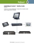
USB Audio Design Guide
REV 6.1
Publication Date: 2013/4/9
XMOS © 2013, All Rights Reserved.
USB Audio Design Guide
2/61
SYNOPSIS
The XMOS USB Audio solution provides USB Audio Class compliant devices over USB 2.0 (highspeed or full-speed). Based on the XMOS XS1 architecture, it supports USB Audio Class 2.0 and
USB Audio Class 1.0, asynchronous mode and sample rates up to 192kHz.
The complete source code, together with the free XMOS xTIMEcomposer development tools
and XCORE multicore microcontroller devices allow the implementer to select the exact mix of
interfaces and processing required.
The XMOS USB Audio solution is provided as a framework. Reference design applications are
provided which are based on this framework. These reference designs have particular qualified
feature set and an accommpanying reference hardware platform.
This software design guide assumes the reader is familiar with the XC language and XCORE
devices. For more information see Programming XC on XMOS Devices1 .
The information in this guide is valid with respect to XMOS USB Audio software release version
6v10.
1 https://www.xmos.com/products/documentation/programming-xc-xmos-devices
REV 6.1
USB Audio Design Guide
3/61
Table of Contents
1 Overview
4
2 Hardware Platforms
2.1 USB Audio 2.0 Hardware Reference Design (L-Series) . . . . . . . . . . . . . . . . . . .
2.2 USB Audio 2.0 Multichannel Hardware Reference Design (L-Series) . . . . . . . . . . .
2.3 USB Audio 2.0 DJ Kit (U-Series) . . . . . . . . . . . . . . . . . . . . . . . . . . . . . . .
5
5
6
6
3 Software Architecture
3.1 Validated Build Options . . . . . . . . . . . . . . . . . . . .
3.2 Binary Naming . . . . . . . . . . . . . . . . . . . . . . . . .
3.3 The USB Audio System Architecture . . . . . . . . . . . . .
3.4 USB Audio Class Support . . . . . . . . . . . . . . . . . . .
3.4.1 Driver Support . . . . . . . . . . . . . . . . . . . . .
3.4.2 Audio Class 1.0 Mode and Fall-back . . . . . . . .
3.5 USB Interface . . . . . . . . . . . . . . . . . . . . . . . . . .
3.5.1 Endpoint 0: Management and Control . . . . . . .
3.5.2 Startup/Enumeration . . . . . . . . . . . . . . . . .
3.5.3 Reset . . . . . . . . . . . . . . . . . . . . . . . . . .
3.5.4 Audio Request: Setting The Sample Rate . . . . .
3.5.5 Audio Request: Volume Control . . . . . . . . . . .
3.6 Audio Endpoints (Endpoint Buffer and Decoupler) . . . .
3.6.1 Endpoint Buffer . . . . . . . . . . . . . . . . . . . .
3.6.2 Decoupler . . . . . . . . . . . . . . . . . . . . . . .
3.6.3 Audio Buffering Scheme . . . . . . . . . . . . . . .
3.6.4 Decoupler/Audio core interaction . . . . . . . . .
3.7 Device Firmware Upgrade (DFU) . . . . . . . . . . . . . . .
3.8 Audio Driver . . . . . . . . . . . . . . . . . . . . . . . . . .
3.8.1 Port Configuration (CODEC Slave) . . . . . . . . . .
3.8.2 Changing Audio Sample Frequency . . . . . . . . .
3.9 Digital Mixer . . . . . . . . . . . . . . . . . . . . . . . . . .
3.9.1 Control . . . . . . . . . . . . . . . . . . . . . . . . .
3.9.2 Host Control . . . . . . . . . . . . . . . . . . . . . .
3.10 S/PDIF Transmit . . . . . . . . . . . . . . . . . . . . . . . .
3.10.1 Clocking . . . . . . . . . . . . . . . . . . . . . . . .
3.10.2 Usage . . . . . . . . . . . . . . . . . . . . . . . . . .
3.10.3 Output stream structure . . . . . . . . . . . . . . .
3.11 S/PDIF Receive . . . . . . . . . . . . . . . . . . . . . . . . .
3.11.1 Integration . . . . . . . . . . . . . . . . . . . . . . .
3.12 ADAT Receive . . . . . . . . . . . . . . . . . . . . . . . . .
3.12.1 Integration . . . . . . . . . . . . . . . . . . . . . . .
3.13 Clock Recovery . . . . . . . . . . . . . . . . . . . . . . . . .
3.14 MIDI . . . . . . . . . . . . . . . . . . . . . . . . . . . . . . .
3.15 Audio Controls via Human Interface Device (HID) . . . . .
3.16 Apple Authentication (iAP) . . . . . . . . . . . . . . . . . .
3.17 Resource Usage . . . . . . . . . . . . . . . . . . . . . . . .
3.18 The USB Audio 2.0 Reference Design (L-Series) Software .
3.18.1 Port 32A . . . . . . . . . . . . . . . . . . . . . . . .
3.18.2 Clocking . . . . . . . . . . . . . . . . . . . . . . . .
3.18.3 HID . . . . . . . . . . . . . . . . . . . . . . . . . . .
REV 6.1
.
.
.
.
.
.
.
.
.
.
.
.
.
.
.
.
.
.
.
.
.
.
.
.
.
.
.
.
.
.
.
.
.
.
.
.
.
.
.
.
.
.
.
.
.
.
.
.
.
.
.
.
.
.
.
.
.
.
.
.
.
.
.
.
.
.
.
.
.
.
.
.
.
.
.
.
.
.
.
.
.
.
.
.
.
.
.
.
.
.
.
.
.
.
.
.
.
.
.
.
.
.
.
.
.
.
.
.
.
.
.
.
.
.
.
.
.
.
.
.
.
.
.
.
.
.
.
.
.
.
.
.
.
.
.
.
.
.
.
.
.
.
.
.
.
.
.
.
.
.
.
.
.
.
.
.
.
.
.
.
.
.
.
.
.
.
.
.
.
.
.
.
.
.
.
.
.
.
.
.
.
.
.
.
.
.
.
.
.
.
.
.
.
.
.
.
.
.
.
.
.
.
.
.
.
.
.
.
.
.
.
.
.
.
.
.
.
.
.
.
.
.
.
.
.
.
.
.
.
.
.
.
.
.
.
.
.
.
.
.
.
.
.
.
.
.
.
.
.
.
.
.
.
.
.
.
.
.
.
.
.
.
.
.
.
.
.
.
.
.
.
.
.
.
.
.
.
.
.
.
.
.
.
.
.
.
.
.
.
.
.
.
.
.
.
.
.
.
.
.
.
.
.
.
.
.
.
.
.
.
.
.
.
.
.
.
.
.
.
.
.
.
.
.
.
.
.
.
.
.
.
.
.
.
.
.
.
.
.
.
.
.
.
.
.
.
.
.
.
.
.
.
.
.
.
.
.
.
.
.
.
.
.
.
.
.
.
.
.
.
.
.
.
.
.
.
.
.
.
.
.
.
.
.
.
.
.
.
.
.
.
.
.
.
.
.
.
.
.
.
.
.
.
.
.
.
.
.
.
.
.
.
.
.
.
.
.
.
.
.
.
.
.
.
.
.
.
.
.
.
.
.
.
.
.
.
.
.
.
.
.
.
.
.
.
.
.
.
.
.
.
.
.
.
.
.
.
.
.
.
.
.
.
.
.
.
.
.
.
.
.
.
.
.
.
.
.
.
.
.
.
.
.
.
.
.
.
.
.
.
.
.
.
.
.
.
.
.
.
.
.
.
.
.
.
.
.
.
.
.
.
.
.
.
.
.
.
.
.
.
.
.
.
.
.
.
.
.
.
.
.
.
.
.
.
.
.
.
.
.
.
.
.
.
.
.
.
.
.
.
.
.
.
.
.
.
.
.
.
.
.
.
.
.
.
.
.
.
.
.
.
.
.
.
.
.
.
.
.
.
.
.
.
.
.
.
.
.
.
.
.
.
.
.
.
.
.
.
.
.
.
.
.
.
.
.
.
.
.
.
.
.
.
.
.
.
.
.
.
.
.
.
.
.
.
.
.
.
.
.
.
.
.
.
.
.
.
.
.
.
.
.
.
.
.
.
.
.
.
.
.
.
.
.
.
.
8
8
9
10
11
12
12
12
13
13
13
14
14
14
14
14
15
15
17
18
19
20
20
21
21
23
24
24
24
25
26
27
28
28
28
28
29
30
30
32
32
34
USB Audio Design Guide
4/61
3.18.4 Validated Build Options . . . . . . . . . . .
3.19 The USB Audio 2.0 DJ Kit (U-Series) . . . . . . . . .
3.19.1 Clocking and Clock Selection . . . . . . . .
3.19.2 CODEC Configuration . . . . . . . . . . . . .
3.19.3 U-Series ADC . . . . . . . . . . . . . . . . . .
3.19.4 HID Example . . . . . . . . . . . . . . . . . .
3.19.5 Validated Build Options . . . . . . . . . . .
3.20 The USB Audio 2.0 Multichannel Reference Design
3.20.1 Clocking . . . . . . . . . . . . . . . . . . . .
3.20.2 Validated Build Options . . . . . . . . . . .
. . . . . . . . . . . .
. . . . . . . . . . . .
. . . . . . . . . . . .
. . . . . . . . . . . .
. . . . . . . . . . . .
. . . . . . . . . . . .
. . . . . . . . . . . .
(L-Series) Software .
. . . . . . . . . . . .
. . . . . . . . . . . .
.
.
.
.
.
.
.
.
.
.
.
.
.
.
.
.
.
.
.
.
.
.
.
.
.
.
.
.
.
.
.
.
.
.
.
.
.
.
.
.
.
.
.
.
.
.
.
.
.
.
.
.
.
.
.
.
.
.
.
.
.
.
.
.
.
.
.
.
.
.
.
.
.
.
.
.
.
.
.
.
34
35
36
36
36
37
37
39
39
39
4 Programming Guide
4.1 Getting Started . . . . . . . . . . . . . . . . . . .
4.1.1 Installing the application onto flash . .
4.2 Code Structure . . . . . . . . . . . . . . . . . . .
4.2.1 Applications and Modules . . . . . . . .
4.3 A USB Audio Application (walkthrough) . . . .
4.3.1 Custom Defines . . . . . . . . . . . . . .
4.3.2 Configuration Functions . . . . . . . . .
4.3.3 The main program . . . . . . . . . . . .
4.4 Adding Custom Code . . . . . . . . . . . . . . .
4.4.1 Example: Changing output format . . .
4.4.2 Example: Adding DSP to output stream
.
.
.
.
.
.
.
.
.
.
.
.
.
.
.
.
.
.
.
.
.
.
.
.
.
.
.
.
.
.
.
.
.
.
.
.
.
.
.
.
.
.
.
.
.
.
.
.
.
.
.
.
.
.
.
.
.
.
.
.
.
.
.
.
.
.
.
.
.
.
.
.
.
.
.
.
.
.
.
.
.
.
.
.
.
.
.
.
.
.
.
.
.
.
.
.
.
.
.
.
.
.
.
.
.
.
.
.
.
.
.
.
.
.
.
.
.
.
.
.
.
.
.
.
.
.
.
.
.
.
.
.
.
.
.
.
.
.
.
.
.
.
.
.
.
.
.
.
.
.
.
.
.
.
.
.
.
.
.
.
.
.
.
.
.
.
.
.
.
.
.
.
.
.
.
.
.
.
.
.
.
.
.
.
.
.
.
.
.
.
.
.
.
.
.
.
.
.
.
.
.
.
.
.
.
.
.
.
.
.
.
.
.
.
.
.
.
.
.
.
.
.
.
.
.
.
.
.
.
.
.
.
.
.
.
.
.
.
.
.
.
.
42
42
43
43
43
44
44
46
48
50
51
51
5 API
5.1 Custom Defines . . . . . . . . . . . . . . .
5.1.1 System Feature Configuration . . .
5.1.2 USB Device Configuration Options
5.2 Required User Function Definitions . . . .
5.2.1 Codec Configuration Functions . .
5.2.2 Clocking Configuration Functions
5.2.3 Audio Streaming Functions . . . .
5.3 Component API . . . . . . . . . . . . . . .
.
.
.
.
.
.
.
.
.
.
.
.
.
.
.
.
.
.
.
.
.
.
.
.
.
.
.
.
.
.
.
.
.
.
.
.
.
.
.
.
.
.
.
.
.
.
.
.
.
.
.
.
.
.
.
.
.
.
.
.
.
.
.
.
.
.
.
.
.
.
.
.
.
.
.
.
.
.
.
.
.
.
.
.
.
.
.
.
.
.
.
.
.
.
.
.
.
.
.
.
.
.
.
.
.
.
.
.
.
.
.
.
.
.
.
.
.
.
.
.
.
.
.
.
.
.
.
.
.
.
.
.
.
.
.
.
.
.
.
.
.
.
.
.
.
.
.
.
.
.
.
.
.
.
.
.
.
.
.
.
.
.
.
.
.
.
.
.
.
.
.
.
.
.
.
.
52
52
52
53
53
53
54
54
54
REV 6.1
.
.
.
.
.
.
.
.
.
.
.
.
.
.
.
.
.
.
.
.
.
.
.
.
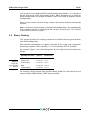
1 Overview
Functionality
Provides USB interface to digital audio I/O.
Supported Standards
USB
USB 2.0 (Full-speed and High-speed)
USB Audio Class 1.02
USB Audio Class 2.03
USB Firmware Upgrade (DFU) 1.14
USB Midi Device Class 1.05
Audio
I2S
S/PDIF
ADAT
MIDI
Supported Sample Frequencies
44.1kHz, 48kHz, 88.2kHz, 96kHz, 176.4kHz, 192kHz
Supported Devices
XMOS Devices
XS1 L-Series
XS1 U-Series
Requirements
Development Tools xTIMEcomposer Development Tools
v12 or later
USB
1 x ULPI USB Phy (If using XS1 L-Series)
Audio
Audio input/output
DAC/ADC/CODECs supporting I2S
Boot/Storage
Compatible SPI Flash device
Licensing and Support
Reference code provided without charge under license from XMOS.
Submit a ticket via http://www.xmos.com/secure/tickets for details.
Reference code is maintained by XMOS Limited.
2 http://www.usb.org/developers/devclass_docs/audio10.pdf
3 http://www.usb.org/developers/devclass_docs/Audio2.0_final.zip
4 http://www.usb.org/developers/devclass_docs/DFU_1.1.pdf
5 http://www.usb.org/developers/devclass_docs/midi10.pdf
REV 6.1
2 Hardware Platforms
IN THIS CHAPTER
· USB Audio 2.0 Hardware Reference Design (L-Series)
· USB Audio 2.0 Multichannel Hardware Reference Design (L-Series)
· USB Audio 2.0 DJ Kit (U-Series)
The following sections describe the hardware platforms that support development
with the XMOS USB audio software platform.
2.1
USB Audio 2.0 Hardware Reference Design (L-Series)
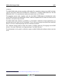
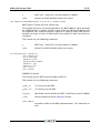
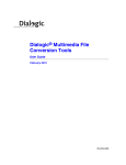
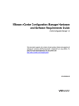
The USB Audio 2.0 Reference Design (L-Series)6 is a hardware reference design
available from XMOS. The diagram in Figure 1 shows the block layout of the USB
Audio 2.0 Reference Design board. The main purpose of the XS1 L-Series device is
to provide a USB Audio interface to the USB PHY and route the audio to the audio
CODEC and S/PDIF output. Note that although the software supports MIDI, there
are no MIDI connectors on the board. For full details please refer to the hardware
manual found on the XMOS website.
13MHz
Oscillator
XSYS
Debug
JTAG
USB
High Speed
480Mb/s
USB
Series B
Receptacle
USB
Transceiver
USB3318
1MBit
FLASH
Resync
SPI
ULPI
MCLK
I2S
24 bit 192kHz
Stereo Audio
CODEC
CS4270
+5V VBus
Figure 1:
USB Audio
2.0 Reference
Design Block
Diagram
8’.’
1.0V DC-DC
Tile
Supply
4.3V LDO
CODEC
Analogue
Supply
User
LEDs
6 http://www.xmos.com/products/development-kits/usbaudio2
REV 6.1
Optical
Digital Audio
Transmitter
Analog Out
1Vrms at
Full Scale
Passive
LPF
‘-244
Stereo
TRS Jack
Passive
LPF
‘-244
Stereo
TRS Jack
Analog In
2Vrms at
Full Scale
1.8V LDO
3.3V LDO
S/PDIF
Push-button
Switches
Audio Master
Clock Oscillator
Produces
24.576MHz
or
11.2896MHz
USB Audio Design Guide
7/61
The reference board has an associated firmware application that uses the USB
Audio 2.0 software reference platform. Details of this application can be found in
section §3.18.
2.2
USB Audio 2.0 Multichannel Hardware Reference Design (L-Series)
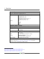
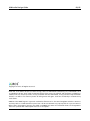
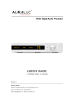
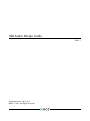
The USB Audio 2.0 Multichannel Reference Design (L-Series)7 is a hardware reference design available from XMOS. The Figure 2 shows the block layout of the USB
Audio 2.0 Multichannel Reference Design board. The board supports six analogue
inputs and eight analogue outputs (via a CS4244 CODEC), digital input and output
(via coax and optical connectors) and MIDI input and output. For full details please
refer to the hardware manual available on the XMOS website.
<=
012..
012..
012..
012..
012..
Figure 2:
USB Audio
2.0
Multichannel
Reference
Design Block
Diagram
012..
012..
012..
The reference board has an associated firmware application that uses the USB
Audio 2.0 software reference platform. Details of this application can be found in
section §3.20.
2.3
USB Audio 2.0 DJ Kit (U-Series)
The XMOS USB Audio 2.0 DJ kit (XS1 U-Series)8 is a hardware reference design
available from XMOS.
The kit is made up of two boards a “core” board and an “audio slice” board. Part
numbers XP-SKC-SU1 and XA-SK-AUDIO respectively.
7 http://www.xmos.com/products/development-kits/usbaudio2mc
8 http://www.xmos.com/products/development-kits/usbaudio2
REV 6.1
USB Audio Design Guide
8/61
The core board includes a U-Series device with integrated USB PHY. The audio slice
board is equipped with two stereo audio CODECs giving 4 channels of input and 4
channels of output at sample frequencies up to 192kHz.
In addition to analogue channels the audio slice board also has MIDI input and
output connectors and a COAX connector for S/PDIF output.
REV 6.1
3 Software Architecture
IN THIS CHAPTER
· Validated Build Options
· Binary Naming
· The USB Audio System Architecture
· USB Audio Class Support
· USB Interface
· Audio Endpoints (Endpoint Buffer and Decoupler)
· Device Firmware Upgrade (DFU)
· Audio Driver
· Digital Mixer
· S/PDIF Transmit
· S/PDIF Receive
· ADAT Receive
· Clock Recovery
· MIDI
· Audio Controls via Human Interface Device (HID)
· Apple Authentication (iAP)
· Resource Usage
· The USB Audio 2.0 Reference Design (L-Series) Software
· The USB Audio 2.0 DJ Kit (U-Series)
· The USB Audio 2.0 Multichannel Reference Design (L-Series) Software
The following sections describe the system architecture of the XMOS USB Audio
software platform.
3.1
Validated Build Options
As previously described the XMOS USB Audio solution is provided as a framework
with reference design applications provided using this frame work running on a
reference hardware platform.
For each reference design an application is provided which extends and customises
the framework to operate on the particular reference platform.
Due to the flexibility of the framework there are many different build options. For
example input and output channel count, Audio Class version, interface types etc
REV 6.1
USB Audio Design Guide
10/61
This results in many potential build configuration permutations. It is not possible for all of these to be exhaustively tested. XMOS therefore test a subset of
build configurations for proper behaviour, these are based on popular device
configurations.
Please see the various reference design sections for relevant validated build configurations.
When a reference design project is compiled all configurations are automatically
built. A naming scheme is employed to link a feature set to binaries. This scheme
is described in the next section.
3.2
Binary Naming
This section describes the naming scheme for the default binaries generated for
each build configuration
Each relevant build option is assigned a position in the string, with a character
denoting the options value (normally ‘x’ is used to denote “off” or “disabled”
For example, Figure 3 lists the build options for the single tile L-Series Reference
Design.
Figure 3:
Single tile
L-Series build
options
Build Option Name
Options
Denoted by
Audio Class Version
1 or 2
1 or 2
Audio Input
on or off
i or x
Audio Output
on or off
o or x
MIDI
on or off
m or x
S/PDIF Output
on or off
s or x
For example a binary named 2ioxs would indicate Audio Class 2.0 with input and
output enabled, MIDI disabled, SPDIF output enabled.
REV 6.1
USB Audio Design Guide
3.3
11/61
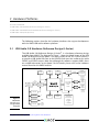
The USB Audio System Architecture
The XMOS USB Audio platform consists of a series of communicating components.
Every system is required to have the shared components listed in Figure 4.
Figure 4:
Shared
Components
Component
Description
XMOS USB Device Driver (XUD)
Handles the low level USB I/O.
Endpoint 0
Provides the logic for Endpoint 0 which handles
enumeration and control of the device.
Endpoint buffer
Buffers endpoint data packets to and from the host.
Decoupler
Manages delivery of audio packets between the
endpoint buffer component and the audio components.
It can also handle volume control processing.
Audio Driver
Handles audio I/O over I2S and manages audio data
to/from other digital audio I/O components.
In addition Figure 5 shows components that can be added to a design:
Figure 5:
Optional
Components
Component
Description
Device Firmware Upgrade (DFU)
Allows firmware upgrade over USB. This is an
optional part of the Endpoint 0 component.
Mixer
Allows digital mixing of input and output channels. It
can also handle volume control instead of the
decoupler.
S/PDIF Transmitter
Outputs samples of an S/PDIF digital audio interface.
S/PDIF Receiver
Inputs samples of an S/PDIF digital audio interface
(requires the clockgen component).
ADAT Receiver
Inputs samples of an ADAT digital audio interface
(requires the clockgen component).
Clockgen
Drives an external frequency generator (PLL) and
manages changes between internal clocks and
external clocks arising from digital input.
MIDI
Outputs and inputs MIDI over a serial UART interface.
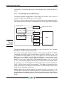
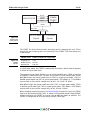
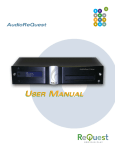
Figure 6 shows how the components interact with each other.
In addition to the overall framework, reference design applications are provided
(described in § 3.18, § 3.20 and § 3.19). These applications provide qualified
configurations of the framework which support and are validated on accompanying
hardware.
REV 6.1
USB Audio Design Guide
12/61
Figure 6:
USB Audio
Component
Architecture
3.4
USB Audio Class Support
The XMOS USB Audio framework supports both USB Audio Class 1.0 and Audio
Class 2.0.
USB Audio Class 2.0 offers many improvements over USB Audio Class 1.0 including:
· Added support for multiple clock domains, clock description and clock control
· Extensive support for interrupts to inform the host about dynamic changes that
occur to different entities such as Clocks etc
However, most notable is the complete support for high-speed operation. Audio
class devices are no longer limited to full-speed operation.
This allows greater channel counts, sample frequencies and sample bit-depths.
REV 6.1
USB Audio Design Guide
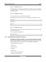
3.4.1
13/61
Driver Support
Audio Class 1.0 had been fully supported in Apple OSX for many years. Audio
Class 2.0 has been fully supported in Apple OSX since version 10.6.4.
Audio Class 1.0 is fully supported in all modern Microsoft Windows operating
systems (i.e. Windows XP and later). Audio Class 2.0 is not supported natively by
Windows operating systems, a driver is required to be installed. Please contact
XMOS for further details.
3.4.2
Audio Class 1.0 Mode and Fall-back
The normal default for XMOS USB Audio applications is to run as a high-speed
Audio Class 2.0 device. However, some products may prefer to run in Audio Class
1.0 mode, this is normally to allow “driver-less” operation with Windows operating
systems.
Note: To ensure specification compliance, Audio Class 1.0 mode always operates
at full-speed.
The device will operate in full-speed Audio Class 1.0 mode if:
· The code is compiled for USB Audio Class 1.0 only.
· The code is compiled for USB Audio Class 2.0 and it is connected to the host
over a full speed link (and Audio Class fall back is enabled).
The options to control this behavior are detailed in §5.1. When running in Audio
Class 1.0 mode the following restrictions apply:
· MIDI is disabled.
· DFU is disabled (Since Windows operating systems would prompt for a DFU
driver to be installed)
Due to bandwidth limitations of full-speed USB the following sample-frequency
restrictions are also applied:
· Sample rate is limited to a maximum of 48kHz if both input and output are
enabled.
· Sample rate is limited to a maximum of 96kHz if only input or output is enabled.
3.5
USB Interface
The low-level USB interface is controlled by the XMOS USB Device (XUD) driver. This
driver is described in the XUD library documentation9
The low level USB interface communicates with two other cores:
9 http://www.xmos.com/published/xuddg
REV 6.1
USB Audio Design Guide
14/61
· The Endpoint 0 core controls the enumeration/configuration tasks of the USB
device.
· The buffering core sends/receives data packets from the XUD library. The core
receives audio data from the decoupler core, MIDI data from the MIDI core etc.
3.5.1
Endpoint 0: Management and Control
Endpoint 0 (endpoint0.xc) controls the management tasks of the USB device.
These tasks can be generally split into enumeration, reset, audio configuration and
firmware upgrade.
3.5.2
Startup/Enumeration
When the device is first attached to a host, enumeration occurs. The device presents
several interfaces to the host via a set of descriptors.
Figure 7:
USB devices
presented to
host
Mode
Interfaces
Application mode
Audio Class 2/Audio Class 1
DFU Class 1.1
MIDI Device Class 1.0
DFU mode
DFU Class 1.1
The device initially starts in Application mode.
§3.7 describes how DFU mode is used. The audio device class (1 or 2) is set at
compile time—see §5.1.
Common enumeration requests are largely handled by the call to
DescriptorRequests() using data structures found in the descriptors_2.h file.
These structures use defines which can be customized—see §5.1.
This function returns 0 if the request was fully handled (and thus no further action
is required). The function returns 1 if the request was not recognised by the
DescriptorRequests() function and further parsing is required to deal with the
request. The function returns -1 if a USB bus reset has been communicated from
XUD to Endpoint 0.
3.5.3
Reset
On receiving a reset request, three steps occur:
1. Depending on the DFU state, the device may be set into DFU mode.
2. A XUD function is called to reset the endpoint structure and receive the new
bus speed.
REV 6.1
USB Audio Design Guide
3.5.4
15/61
Audio Request: Setting The Sample Rate
When the host requests a change of sample rate, it sends a command to Endpoint
0.
Since the DescriptorRequests() function does not deal with audio requests it returns 1. After some parsing the request is handled by either the AudioRequests_1()
or AudioRequests_2() function (based on whether the device is running in Audio
Class 1.0 or 2.0 mode).
3.5.5
Audio Request: Volume Control
When the host requests a volume change, it sends an audio interface request to
Endpoint 0. An array is maintained in the Endpoint 0 core that is updated with
such a request.
When changing the volume, Endpoint 0 applies the master volume and channel
volume, producing a single volume value for each channel. These are stored in the
array.
The volume will either be handled by the decoupler or the mixer component (if the
mixer component is used). Handling the volume in the mixer gives the decoupler
more performance to handle more channels.
If the effect of the volume control array on the audio input and output is implemented by the decoupler, the decoupler core reads the volume values from this
array. Note that this array is shared between Endpoint 0 and the decoupler core.
This is done in a safe manner, since only Endpoint 0 can write to the array, word
update is atomic between cores and the decoupler core only reads from the array
(ordering between writes and reads is unimportant in this case). Inline assembly is
used by the decoupler core to access the array, avoiding the parallel usage checks
in XC.
If volume control is implemented in the mixer, Endpoint 0 sends a mixer command
to the mixer to change the volume. Mixer commands are described in §3.9.
3.6
Audio Endpoints (Endpoint Buffer and Decoupler)
3.6.1
Endpoint Buffer
All endpoints other that Endpoint 0 are handled in one core. This core is implemented in the file usb_buffer.xc. This loop is responsive to the XUD library.
This core is also responsible for feedback calculation based on SOF notification
and reads from the port counter of a port connected to the master clock.
3.6.2
Decoupler
The decoupler supplies the USB buffering core with buffers to transmit/receive
audio data to/from the host. It marshals these buffers into FIFOs. The data from
the FIFOs are then sent over XC channels to other parts of the system as they need
REV 6.1
USB Audio Design Guide
16/61
it. This core also determines the size of each packet of audio sent to the host (thus
matching the audio rate to the USB packet rate). The decoupler is implemented in
the file decouple.xc.
3.6.3
Audio Buffering Scheme
Both audio and MIDI use a similar buffering scheme for USB data. This scheme is
executed by co-operation between the buffering core, the decouple core and the
XUD library.
For data going from the device to the host the following scheme is used:
1. The decouple core receives samples from the audio core and puts them into a
FIFO. This FIFO is split into packets when data is entered into it. Packets are
stored in a format consisting of their length in bytes followed by the data.
2. When the buffer cores needs a buffer to send to the XUD core (after sending the
previous buffer), the decouple core is signalled (via a shared memory flag).
3. Upon this signal from the buffering core, the decouple core passes the next
packet from the FIFO to the buffer core. It also signals to the XUD library that
the buffer core is able to send a packet.
4. When the buffer core has sent this buffer, it signals to the decouple that the
buffer has been sent and the decouple core moves the read pointer of the FIFO.
For data going from the host to the device the following scheme is used:
1. The decouple core passes a pointer to the buffering core pointing into a FIFO of
data and signals to the XUD library that the buffering core is ready to receive.
2. The buffering core then reads a USB packet into the FIFO and signals to the
decoupler that the packet has been read.
3. Upon receiving this signal the decoupler core updates the write pointer of the
FIFO and provides a new pointer to the buffering core to fill.
4. Upon request from the audio core, the decoupler core sends samples to the
audio core by reading samples out of the FIFO.
3.6.4
Decoupler/Audio core interaction
To meet timing requirements of the audio system, the decoupler core must respond
to requests from the audio system to send/receive samples immediately. An
interrupt handler is set up in the decoupler core to do this. The interrupt handler
is implemented in the function handle_audio_request.
The audio system sends a word over a channel to the decouple core to request
sample transfer (using the build in outuint function). The receipt of this word in
the channel causes the handle_audio_request interrupt to fire.
REV 6.1
USB Audio Design Guide
17/61
The first operation the interrupt handler does is to send back a word acknowledging
the request (if there was a change of sample frequency a control token would
instead be sent—the audio system uses a testct() to inspect for this case).
Sample transfer may now take place. First the audio subsystem transfers samples
destined for the host, then the decouple core sends samples from the host to
device. These transfers always take place in channel count sized chunks (i.e.
NUM_USB_CHAN_OUT and NUM_USB_CHAN_IN). That is, if the device has 10 output
channels and 8 input channels, 10 samples are sent from the decouple core and 8
received every interrupt.
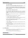
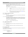
The complete communication scheme is shown in the table below (for non sample
frequency change case):
Decouple
Audio System
Note
outuint()
Audio system requests sample exchange
inuint()
Interrupt fires and inuint performed
outuint()
Decouple sends ack
testct()
Checks for CT indicating SF change
inuint()
Word indication ACK input (No SF change)
inuint()
Sample transfer (Device to Host)
inuint()
inuint()
...
Figure 8:
Decouple/Audio
System
Channel Communication
outuint()
Sample transfer (Host to Device)
outuint()
outuint()
outuint()
...
3.6.4.1
Aysnc Feedback
The device uses a feedback endpoint to report the rate at which audio is output/input to/from external audio interfaces/devices. This feedback is in accordance with
the USB Audio Class 2.0 specification.
After each received USB SOF token, the buffering core takes a timestamp from
a port clocked off the master clock. By subtracting the timestamp taken at the
previous SOF, the number of master clock ticks since the last SOF is calculated.
From this the number of samples (as a fixed point number) between SOFs can be
calculated. This count is aggregated over 128 SOFs and used as a basis for the
feedback value.
The sending of feedback to the host is also handled in the USB buffering core.
REV 6.1
USB Audio Design Guide
3.6.4.2
18/61
USB Rate Control
The Audio core must consume data from USB and provide data to USB at the correct
rate for the selected sample frequency. The USB 2.0 Specification states that the
maximum variation on USB packets can be +/- 1 sample per USB frame. USB frames
are sent at 8kHz, so on average for 48kHz each packet contains six samples per
channel. The device uses Asynchronous mode, so the audio clock may drift and run
faster or slower than the host. Hence, if the audio clock is slightly fast, the device
may occasionally input/output seven samples rather than six. Alternatively, it may
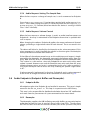
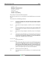
be slightly slow and input/output five samples rather than six. Figure 9 shows the
allowed number of samples per packet for each example audio frequency.
See USB Device Class Definition for Audio Data Formats v2.0 section 2.3.1.1 for
full details.
Figure 9:
Allowed
samples per
packet
Frequency (kHz)
Min Packet
Max Packet
44.1
5
6
48
5
7
88.2
10
11
96
11
13
176.4
20
21
192
23
25
To implement this control, the decoupler core uses the feedback value calculated
in the buffering core. This value is used to work out the size of the next packet it
will insert into the audio FIFO.
3.7
Device Firmware Upgrade (DFU)
The DFU interface handles updates to the boot image of the device. The interface
links USB to the XMOS flash user library (see XM-000953-PC). In Application mode
the DFU can accept commands to reset the device into DFU mode. There are two
ways to do this:
· The host can send a DETACH request and then reset the device. If the device is
reset by the host within a specified timeout, it will start in DFU mode (this is
initially set to one second and is configurable from the host).
· The host can send a custom user request XMOS_DFU_RESETDEVICE to the DFU
interface that resets the device immediately into DFU mode.
Once the device is in DFU mode. The DFU interface can accept commands defined
by the DFU 1.1 class specification10 . In addition the interface accepts the custom
command XMOS_DFU_REVERTFACTORY which reverts the active boot image to the
factory image. Note that the XMOS specific command request identifiers are
defined in dfu_types.h within module_dfu.
10 http://www.usb.org/developers/devclass_docs/DFU_1.1.pdf*USB
REV 6.1
USB Audio Design Guide
3.8
19/61
Audio Driver
The audio driver receives and transmits samples from/to the decoupler or mixer
core over an XC channel. It then drives several in and out I2S channels. If the
firmware is configured with the CODEC as slave, it will also drive the word and bit
clocks in this core as well. The word clocks, bit clocks and data are all derived
from the incoming master clock (the output of the external clocking chip). The
audio driver is implemented in the file audio.xc.
The audio driver captures and plays audio data over I2S. It also forwards on relevant
audio data to the S/PDIF transmit core.
The audio core must be connected to a CODEC that supports I2S (other modes
such as “left justified” can be supported with firmware changes). In slave mode,
the XS1 device acts as the master generating the Bit Clock (BCLK) and Left-Right
Clock (LRCLK, also called Word Clock) signals. Although the reference designs use
the Cirrus CS4270/CS42448, any CODEC that supports I2S and can be used.
Figure 10 shows the signals used to communicate audio between the XS1 device
and the CODEC.
Figure 10:
CODEC
Signals
Signal
Description
LRCLK
The word clock, transition at the start of a sample
BCLK
The bit clock, clocks data in and out
SDIN
Sample data in (from CODEC to XS1-L)
SDOUT
Sample data out (from XS1-L to CODEC)
MCLK
The master clock running the CODEC
The bit clock controls the rate at which data is transmitted to and from the CODEC.
In the case where the XS1 device is the master, it divides the MCLK to generate
the required signals for both BCLK and LRCLK, with BCLK then being used to clock
data in (SDIN) and data out (SDOUT) of the CODEC.
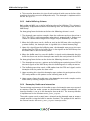
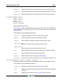
Figure 11 shows some example clock frequencies and divides for different sample
rates (note that this reflects the single tile L-Series reference board configuration):
Figure 11:
Clock Divides
used in single
tile L-Series
Ref Design
Sample Rate (kHz)
MCLK (MHz)
BCLK (MHz)
Divide
44.1
11.2896
2.819
4
88.2
11.2896
5.638
2
176.4
11.2896
11.2896
1
48
24.576
3.072
8
96
24.576
6.144
4
192
24.576
12.288
2
The master clock must be supplied by an external source e.g. clock generator
chip, fixed oscillators, PLL etc to generate the two frequencies to support 44.1kHz
and 48kHz audio frequencies (e.g. 11.2896/22.5792MHz and 12.288/24.576MHz
REV 6.1
USB Audio Design Guide
20/61
respectively). This master clock input is then provided to the CODEC and the XS1
device.
3.8.1
Port Configuration (CODEC Slave)
The default software configuration is CODEC Slave (XS1 master). That is, the XS1
provides the BCLK and LRCLK signals to the CODEC.
XS1 ports and XS1 clocks provide many valuable features for implementing I2S.
This section describes how these are configured and used to drive the I2S interface.
L8A-64-TQ128
p_mclk
Audio master clock
clk_audio_mclk
p_bclk
clk_audio_bclk
Figure 12:
Ports and
Clocks
(CODEC slave)
p_lrclk
CODEC
p_sdin
p_sdout
The code to configure the ports and clocks is in the ConfigAudioPorts() function.
Developers should not need to modify this.
The L-Series device inputs MCLK and divides it down to generate BCLK and LRCLK.
To achieve this, MCLK is input into the device using the 1-bit port p_mclk. This
is attached to the clock block clk_audio_mclk, which is in turn used to clock the
BCLK port, p_bclk. BCLK is used to clock the LRCLK (p_lrclk) and data signals
SDIN (p_sdin) and SDOUT (p_sdout). Again, a clock block is used (clk_audio_bclk)
which has p_bclk as its input and is used to clock the ports p_lrclk, p_sdin and
p_sdout. The preceding diagram shows the connectivity of ports and clock blocks.
p_sdin and p_sdout are configured as buffered ports with a transfer width of 32,
so all 32 bits are input in one input statement. This allows the software to input,
process and output 32-bit words, whilst the ports serialize and deserialize to the
single I/O pin connected to each port.
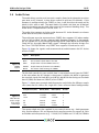
Buffered ports with a transfer width of 32 are also used for p_bclk and p_lrclk.
The bit clock is generated by performing outputs of a particular pattern to p_bclk
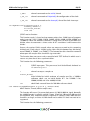
to toggle the output at the desired rate. The pattern depends on the divide between
MCLK and BCLK. The following table shows the pattern for different values of this
divide:
REV 6.1
USB Audio Design Guide
Figure 13:
Output
patterns
21/61
Divide
Output pattern
Outputs per sample
2
0xAAAAAAAA
0xCCCCCCCC
0xF0F0F0F0
2
4
8
4
8
In any case, the bit clock outputs 32 clock cycles per sample. In the special
case where the divide is 1 (i.e. the bit clock frequency equals the master clock
frequency), the p_bclk port is set to a special mode where it simply outputs its
clock input (i.e. p_mclk). See configure_port_clock_output() in xs1.h for details.
p_lrclk is clocked by p_bclk. The port outputs the pattern 0x7fffffff followed
by 0x80000000 repeatedly. This gives a signal that has a transition one bitclock
before the data (as required by the I2S standard) and alternates between high and
low for the left and right channels of audio.
3.8.2
Changing Audio Sample Frequency
When the host changes sample frequency, a new frequency is sent to the audio
driver core by Endpoint 0. First, a change of sample frequency is reported by
sending the new frequency over an XC channel. The audio core detects this using
the select function on a channel (a default case such that processing can continue
if no signal is present on the channel).
Upon receiving the change of sample frequency request, the audio core stops
the I2S interface and calls the CODEC/port configuration functions. Once this is
complete, the I2S interface is restarted at the new frequency.
3.9
Digital Mixer
The mixer core takes outgoing audio from the decoupler and incoming audio from
the audio driver. It then applies the volume to each channel and passes incoming
audio on to the decoupler and outgoing audio to the audio driver. The volume
update is achieved using the built-in 32bit to 64bit signed multiply-accumulate
function (macs). The mixer is implemented in the file mixer.xc.
The mixer takes two cores and can perform eight mixes with up to 18 inputs at
sample rates up to 96kHz and two mixes with up to 18 inputs at higher sample
rates. The component automatically moves down to two mixes when switching to
a higher rate.
The mixer can take inputs from either:
· The USB outputs from the host—these samples come from the decoupler.
· The inputs from the audio interface on the device—these samples come from
the audio driver.
REV 6.1
USB Audio Design Guide
22/61
Since the sum of these inputs may be more then the 18 possible mix inputs to
each mixer, there is a mapping from all the possible inputs to the mixer inputs.
After the mix occurs, the final outputs are created. There are two output destinations:
· The USB inputs to the host—these samples are sent to the decoupler.
· The outputs to the audio interface on the device—these samples are sent to the
audio driver.
For each possible output, a mapping exists to tell the mixer what its source is.
The possible sources are the USB outputs from the host, the inputs for the audio
interface or the outputs from the mixer units.
As mentioned in §3.5.5, the mixer can also handle volume setting. If the mixer
is configured to handle volume but the number of mixes is set to zero (so the
component is solely doing volume setting) then the component will use only one
core.
3.9.1
Control
The mixers can receive the following control commands from the Endpoint 0 core:
Figure 14:
Mixer
Component
Commands
Command
Description
SET_SAMPLES_TO_HOST_MAP
Sets the source of one of the audio streams going to the
host.
SET_SAMPLES_TO_DEVICE_MAP
Sets the source of one of the audio streams going to the
audio driver.
SET_MIX_MULT
SET_MIX_MAP
SET_MIX_IN_VOL
Sets the multiplier for one of the inputs to a mixer.
SET_MIX_OUT_VOL
If volume adjustment is being done in the mixer, this
command sets the volume multiplier of one of the USB
audio outputs.
3.9.2
Sets the source of one of the inputs to a mixer.
If volume adjustment is being done in the mixer, this
command sets the volume multiplier of one of the USB
audio inputs.
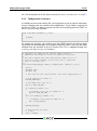
Host Control
The mixer can be controlled from a host PC. XMOS provides a simple command
line based sample application demonstrating how the mixer can be controlled. For
details, consult the README in the host_usb_mixer_control directory.
The main requirements of this control are to
· Set the mapping of input channels into the mixer
· Set the Coefficients for each mixer output of each input
REV 6.1
USB Audio Design Guide
23/61
· Set the mapping for physical outputs which can either come directly from the
inputs or via the mixer.
There is enough flexibility within this configuration there will often be multiple
ways of creating the required solution.
Using the XMOS Host control example application, consider setting the mixer to
perform a loopback from analogue inputs 1 and 2 to analogue outputs 1 and 2.
This must be run with the MultiChannel Audio device connected to the host you
run the mixer app from.
First consider the inputs to the mixer:
./ xmos_mixer -- display - aud - channel - map 0
shows which channels are mapped to which mixer inputs:
./ xmos_mixer -- display - aud - channel - map - sources 0
shows which channels could possibly be mapped to mixer inputs. Notice that
analogue inputs 1 and 2 are on mixer inputs 10 and 11.
Now examine the audio output mapping:
./ xmos_mixer -- display - aud - channel - map 0
This shows which channels are mapped to which outputs. By default all of these
bypass the mixer. We can also see what all the possible mappings are:
./ xmos_mixer -- display - aud - channel - map - sources 0
So now map the first two mixer outputs to physical outputs 1 and 2:
./ xmos_mixer -- set - aud - channel - map 0 26
./ xmos_mixer -- set - aud - channel - map 1 27
You can confirm the effect of this by re-checking the map:
./ xmos_mixer -- display - aud - channel - map 0
This now makes analogue outputs 1 and 2 come from the mixer, rather than
directly from USB. However the mixer is still mapped to pass the USB channels
through to the outputs, so there will still be no functional change yet.
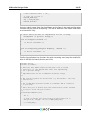
The mixer nodes need to be individually set. They can be displayed with:
./ xmos_mixer -- display - mixer - nodes 0
REV 6.1
USB Audio Design Guide
24/61
To get the audio from the analogue inputs to outputs 1 and 2, nodes 80 and 89
need to be set:
./ xmos_mixer -- set - value 0 80 0
./ xmos_mixer -- set - value 0 89 0
At the same time, the original mixer outputs can be muted:
./ xmos_mixer -- set - value 0 0 - inf
./ xmos_mixer -- set - value 0 9 - inf
Now audio inputs on analogue 1/2 should be heard on outputs 1/2.
As mentioned above, the flexibility of the mixer is such that there will be multiple
ways to create a particular mix. Another option to create the same routing would be
to change the mixer sources such that mixer 1/2 outputs come from the analogue
inputs.
To demonstrate this, firstly undo the changes above:
./ xmos_mixer
./ xmos_mixer
./ xmos_mixer
./ xmos_mixer
-- set - value
-- set - value
-- set - value
-- set - value
0
0
0
0
80 - inf
89 - inf
0 0
9 0
The mixer should now have the default values. The sources for mixer 1/2 can now
be changed:
./ xmos_mixer -- set - mixer - source 0 0 10
./ xmos_mixer -- set - mixer - source 0 1 11
If you rerun:
./ xmos_mixer -- display - mixer - nodes 0
the first column now has AUD - Analogue 1 and 2 rather than DAW - Analogue 1
and 2 confirming the new mapping. Again, by playing audio into analogue inputs
1/2 this can be heard looped through to analogue outputs 1/2.
3.10
S/PDIF Transmit
XS1 devices can support S/PDIF transmit up to 192kHz. The S/PDIF transmitter
uses a lookup table to encode the audio data. It receives samples from the Audio
core two at a time, one for each channel. For each sample, it performs a lookup on
each byte, generating 16 bits of encoded data which it outputs to the port.
S/PDIF sends data in frames, each containing 192 samples of the left and right
channels.
REV 6.1
USB Audio Design Guide
25/61
The core takes PCM audio samples via a channel and outputs them in S/PDIF format
to a port. Audio samples are encapsulated into S/PDIF words (adding preamble,
parity, channel status and validity bits) and transmitted in biphase-mark encoding
(BMC) with respect to an external master clock. Note that a minor change to the
SpdifTransmitPortConfig function would enable internal master clock generation
(e.g. when clock source is already locked to desired audio clock).
Figure 15:
S/PDIF
Capabilities
Sample frequencies
44.1, 48, 88.2, 96, 176.4, 192 kHz
Master clock ratios
128x, 256x, 512x
Module
module_spdif_tx
3.10.1
Clocking
XCORE Tile
MCLK
PORT
via clock block
Figure 16:
D-Type Jitter
Reduction
S/PDIF
DATA
PORT
D-type
S/PDIF
TX
The S/PDIF signal is output at a rate dictated by the external master clock. The
master clock must be 1x 2x or 4x the BMC bit rate (that is 128x 256x or 512x
audio sample rate, respectively). The minimum master clock frequency for 192kHz
is therefore 24.576MHz.
This resamples the master clock to its clock domain (oscillator), which introduces
jitter of 2.5-5 ns on the S/PDIF signal. A typical jitter-reduction scheme is an
external D-type flip-flop clocked from the master clock (as shown in the preceding
diagram).
3.10.2
Usage
The interface is normal channel with streaming built-ins (outuint, inuint). Data
format is 24-bit left-aligned in a 32-bit word: 0x12345600
The following protocol is used on the channel:
3.10.3
Output stream structure
The stream is composed of words with the following structure shown in Figure 18.
The channel status bits are 0x0nc07A4, where c=1 for left channel, c=2 for right
channel and n indicates sampling frequency as shown in Figure 19.
REV 6.1
USB Audio Design Guide
Figure 17:
S/PDIF
Component
Protocol
outuint
outuint
outuint
outuint
outuint
outuint
...
...
outct
26/61
Sample frequency (Hz)
Master clock frequency (Hz)
Left sample
Right sample
Left sample
Right sample
Terminate
Bits
Figure 18:
S/PDIF
Stream
Structure
Figure 19:
Channel
Status Bits
3.11
0:3
Preamble
Correct B M W order, starting at sample 0
4:27
Audio sample
Top 24 bits of given word
28
Validity bit
Always 0
29
Subcode data (user bits)
Unused, set to 0
30
Channel status
See below
31
Parity
Correct parity across bits 4:30
Frequency (kHz)
n
44.1
0
48
2
88.2
8
96
A
176.4
C
192
E
S/PDIF Receive
XS1 devices can support S/PDIF receive up to 192kHz.
The S/PDIF receiver module uses a clockblock and a buffered one-bit port. The
clock-block is divided of a 100 MHz reference clock. The one bit port is buffered
to 4-bits.
The receiver outputs audio samples over a streaming channel end where data can
be input using the built-in input operator.
The S/PDIF receive function never returns. The 32-bit value from the channel input
comprises:
The tag has one of three values:
See S/PDIF specification for further details on format, user bits etc.
REV 6.1
USB Audio Design Guide
27/61
Bits
Figure 20:
S/PDIF RX
Word
Structure
Figure 21:
S/PDIF RX
Tags
0:3
A tag (see below)
4:28
PCM encoded sample value
29:31
User bits (parity, etc)
Tag
Meaning
FRAME_X
Sample on channel 0 (Left for stereo)
FRAME_Y
Sample on another channel (Right if for stereo)
FRAME_Z
Sample on channel 0 (Left), and the first sample of a frame; can be used if
the user bits need to be reconstructed.
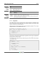
3.11.1
Integration
The S/PDIF receive function communicates with the clockGen component with
passes audio data to the audio driver and handles locking to the S/PDIF clock
source if required (see Clock Recovery).
Ideally the parity of each word/sample received should be checked. This is done
using the built in crc32 function (see xs1.h):
/* Returns 1 for bad parity , else 0 */
static inline int badParity ( unsigned x )
{
unsigned X = (x > >4) ;
crc32 (X , 0 , 1) ;
return X & 1;
}
If bad parity is detected the word/sample is ignored, else the tag is inspected for
channel and the sample stored.
The following code snippet illustrates how the output of the S/PDIF receive component could be used:
while (1) {
c_spdif_rx : > data ;
if ( badParity ( data )
continue ;
tag = data & 0 xF ;
sample = ( data << 4) & 0 xFFFFFF00 ;
switch ( tag )
{
case FRAME_X :
REV 6.1
USB Audio Design Guide
28/61
case FRAME_X :
// Store left
break ;
case FRAME_Z :
// Store right
break ;
}
}
3.12
ADAT Receive
The ADAT component receives up to eight channels of audio at a sample rate of
44.1kHz or 48kHz. The API for calling the receiver functions is described in §5.3.
The component outputs 32 bits words split into nine word frames. The frames are
laid out in the following manner:
· control byte
· channel 0 sample
· channel 1 sample
· channel 2 sample
· channel 3 sample
· channel 4 sample
· channel 5 sample
· channel 6 sample
· channel 7 sample
The following code is an example of code that could read the output of the ADAT
component:
control = inuint ( oChan ) ;
for ( int i = 0; i < 8; i ++) {
sample [ i ] = inuint ( oChan ) ;
}
The samples are 24-bit values contained in the lower 24 bits of the word. The
control word comprises four control bits in bits [11..8] and the value 0b00000001
in bits [7..0]. This enables synchronization at a higher level, in that on the channel
a single odd word is always read followed by eight words of data.
REV 6.1
USB Audio Design Guide
3.12.1
29/61
Integration
The ADAT receive function communicates with the clockGen component which
passes audio data onto the audio driver and handles locking to the ADAT clock
source if required.
3.13
Clock Recovery
An application can either provide fixed master clock sources via selectable oscillators, clock generation IC, etc., to provide the audio master or use an external
PLL/Clock Multiplier to generate a master clock based on reference from the XS1.
Using an external PLL/Clock Multiplier allows the design to lock to an external
clock source from a digital steam (e.g. S/PDIF or ADAT input).
The clock recovery core (clockGen) is responsible for generating the reference
frequency to the Fractional-N Clock Generator. This, in turn, generates the master
clock used over the whole design.
When running in Internal Clock mode this core simply generates this clock using a
local timer, based on the XS1 reference clock.
When running in an external clock mode (i.e. S/PDIF Clock” or “ADAT Clock” mode)
digital samples are received from the S/PDIF and/or ADAT receive core. The
external frequency is calculated through counting samples in a given period. The
reference clock to the Fractional-N Clock Multiplier is then generated based on this
external stream. If this stream becomes invalid, the timer event will fire to ensure
that valid master clock generation continues regardless of cable unplugs etc.
This core gets clock selection Get/Set commands from Endpoint 0 via the c_clk_ctl
channel. This core also records the validity of external clocks, which is also queried
through the same channel from Endpoint 0.
This core also can cause the decouple core to request an interrupt packet on change
of clock validity. This functionality is based on the Audio Class 2.0 status/interrupt
endpoint feature.
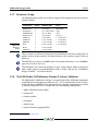
3.14
MIDI
The MIDI driver implements a 31250 baud UART input and output. On receiving
32-bit USB MIDI events from the buffer core, it parses these and translates them
to 8-bit MIDI messages which are sent over UART. Similarly, incoming 8-bit MIDI
messages are aggregated into 32-bit USB-MIDI events and passed on to the buffer
core. The MIDI core is implemented in the file usb_midi.xc.
3.15
Audio Controls via Human Interface Device (HID)
The design supports simple audio controls such as play/pause, volume etc via the
USB Human Interface Device Class Specification.
REV 6.1
USB Audio Design Guide
30/61
This functionality is enabled by setting the HID_CONTROLS define to 1. Setting to 0
disables this feature.
When turned on the following items are enabled:
1. HID descriptors are enabled in the Configuration Descriptor informing the host
that the device has HID interface
2. A Get Report Descriptor request is enabled in endpoint0.
3. Endpoint data handling is enabled in the buffer core
The Get Descriptor Request enabled in endpoint 0 returns the report descriptor for
the HID device. This details the format of the HID reports returned from the device
to the host. It maps a bit in the report to a function such as play/pause.
The USB Audio Framework implements a report descriptor that should fit most basic
audio device controls. If further controls are neccisary the HID Report Descriptor
in descriptors_2.h should be modified. The default report size is 1 byte with the
format as follows:
Figure 22:
Default HID
Report
Format
Bit
Function
0
Play/Pause
1
Scan Next Track
2
Scan Prev Track
3
Volume Up
4
Volume Down
5
Mute
6-7
Unused
On each HID report request from the host the function Vendor_ReadHidButtons(unsigned char h
is called from buffer(). This function is passed an array hidData[] by reference.
The programmer should report the state of his buttons into this array. For
example, if a volume up command is desired, bit 3 should be set to 1, else 0.
Since the Vendor_ReadHidButtons() function is called from the buffer logical core,
care should be taken not to add to much execution time to this functon since this
could cause issues with servicing other endpoints.
For a full example please see the HID section in §3.18.
3.16
Apple Authentication (iAP)
The XMOS device is capable of authenticating with Apple devices that support USB
Host Mode using an Apple Coprocessor IC. Information regarding this process is
protected by the Made For iPod (MFI) program and associated licensing. Please
contact XMOS for details.
REV 6.1
USB Audio Design Guide
3.17
31/61
Resource Usage
The following table details the resource usage of each component of the reference
design software.
Component
Figure 23:
Resource
Usage
Cores
Memory (KB)
Ports
ULPI ports
XUD library
1
9 (6 code)
Endpoint 0
1
17.5 (10.5 code)
none
USB Buffering
1
22.5 (1 code)
none
Audio driver
1
8.5 (6 code)
See §3.8
S/PDIF Tx
1
3.5 (2 code)
1 x 1 bit port
S/PDIF Rx
1
3.7 (3.7 code)
1 x 1 bit port
ADAT Rx
1
3.2 (3.2 code)
1 x 1 bit port
Midi
1
6.5 (1.5 code)
2 x 1 bit ports
Mixer
2
8.7 (6.5 code)
ClockGen
1
2.5 (2.4 code)
These resource estimates are based on the multichannel reference design with all
options of that design enabled. For fewer channels, the resource usage is likely to
decrease.
The XUD library requires an 80MIPS cores to function correctly (i.e. on a 500MHz
parts only six cores can run).
The ULPI ports are a fixed set of ports on the L-Series device. When using these
ports, other ports are unavailable when ULPI is active. See the XS1-L Hardware
Design Checklist11 for further details.
3.18
The USB Audio 2.0 Reference Design (L-Series) Software
The USB Audio 2.0 Reference Design is an application of the USB audio framework
specifically for the hardware described in §2.1 and is implemented on the L-Series
single tile device (500MIPS). The software design supports two channels of audio
at sample frequencies up to 192kHz and uses the following components:
· XMOS USB Device Driver (XUD)
· Endpoint 0
· Endpoint buffer
· Decoupler
· Audio Driver
· Device Firmware Upgrade (DFU)
11 http://www.xmos.com/published/xs1lcheck
REV 6.1
USB Audio Design Guide
32/61
· S/PDIF Transmitter or MIDI
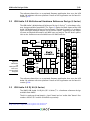
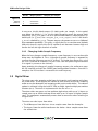
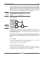
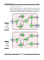
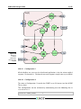
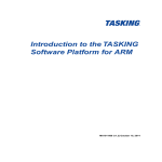
The diagrams Figure 24 and Figure 25 show the software layout of the code running
on the XS1-L chip. Each unit runs in a single core concurrently with the others units.
The lines show the communication between each functional unit. Due to the MIPS
requirement of the USB driver (see §3.17), only six cores can be run on the single
tile L-Series device so only one of S/PDIF transmit or MIDI can be supported.
Figure 24:
Single Tile
L-Series
Software
Core Diagram
(with S/PDIF
TX)
Figure 25:
Single Tile
L-Series
Software
Core Diagram
(with MIDI
I/O)
REV 6.1
USB Audio Design Guide
3.18.1
33/61
Port 32A
Port 32A on the XS1-L device is a 32-bit wide port that has several separate signal
bit signals connected to it, accessed by multiple cores. To this end, any output
to this port must be read-modify-write i.e. to change a single bit of the port, the
software reads the current value being driven across 32 bits, flips a bit and then
outputs the modified value.
This method of port usage (i.e. sharing a port between cores) is outside the
standard XC usage model so is implemented using inline assembly as required.
The peek instruction is used to get the current output value on the port:
/* Peek at current port value using port 32 A resource ID */
asm ( " peek %0 , res [%1] " := r " ( x ) : " r " ( XS1_PORT_32A ) ) ;
The required output value is then assembled using the relevant bit-wise operation(s)
before the out instruction is used directly to output data to the port:
/* Output to port */
asm ( " out res [%0] , %1 " :: " r " ( XS1_PORT_32A ) ," r " ( x ) ) ;
The table Figure 26 shows the signals connected to port 32A on the USB Audio
Class 2.0 reference design board. Note, they are all outputs from the XS1-L device.
Figure 26:
Port 32A
Signals
Pin
Port
Signal
XD49
P32A0
USB_PHY_RST_N
XD50
P32A1
CODEC_RST_N
XD51
P32A2
MCLK_SEL
XD52
P32A3
LED_A
XD53
P32A4
LED_B
3.18.2
Clocking
The board has two on-board oscillators for master clock generation. These produce
11.2896MHz for sample rates 44.1, 88.2, 176.4KHz etc and 24.567MHz for sample
rates 48, 96, 192kHz etc.
The required master clock is selected from one of these using an external mux circuit via port P32A[2] (pin 2 of port 32A). Setting P32A[2] high selects 11.2896MHz,
low selects 24.576MHz.
The reference design board uses a 24 bit, 192kHz stereo audio CODEC (Cirrus
Logic CS4270).
The CODEC is configured to operate in stand-alone mode meaning that no serial
configuration interface is required. The digital audio interface is set to I2S mode
with all clocks being inputs (i.e. slave mode).
REV 6.1
USB Audio Design Guide
34/61
L8A-64-TQ128
BCLK
LR CLK
SDOUT
SDIN
Codec
CS427
0
MCLK
MCLK_SEL
24.576 MHz
Crystal
Figure 27:
Audio Clock
Connections
11.2896 MHz
Crystal
The CODEC has three internal modes depending on the sampling rate used. These
change the oversampling ratio used internally in the CODEC. The three modes are
shown below:
Figure 28:
CODEC
Modes
CODEC mode
CODEC sample rate range (kHz)
Single-Speed
4-54
Double-Speed
50-108
Quad-Speed
100-216
In stand-alone mode, the CODEC automatically determines which mode to operate
in based on input clock rates.
The internal master clock dividers are set using the MDIV pins. MDIV is tied low
and MDIV2 is connected to bit 2 of port 32A (as well as to the master clock select).
With MDIV2 low, the master clock must be 256Fs in single-speed mode, 128Fs in
double-speed mode and 64Fs in quad-speed mode. This allows an 11.2896MHz
master clock to be used for sample rates of 44.1, 88.2 and 176.4kHz.
With MDIV2 high, the master clock must be 512Fs in single-speed mode, 256Fs
in double-speed mode and 128Fs in quad-speed mode. This allows a 24.576MHz
master clock to be used for sample rates of 48, 96 and 192kHz.
When changing sample frequency, the CodecConfig() function first puts the CODEC
into reset by setting P32A[1] low. It selects the required master clock/CODEC
dividers and keeps the CODEC in reset for 1ms to allow the clocks to stabilize. The
CODEC is brought out of reset by setting P32A[1] back high.
REV 6.1
USB Audio Design Guide
3.18.3
35/61
HID
The reference design implements basic HID controls.
The call to
vendor_ReadHidButtons() simply reads from buttons A and B and returns their
state in the relevant bits depending on the desired functionality (play/pause/skip
etc). Note the buttons are active low, the HID controls active high. The buttons are
therefore read and then inverted.
/* Write HID Report Data into hidData array
*
* Bits are as follows :
* 0: Play / Pause
* 1: Scan Next Track
* 2: Scan Prev Track
* 3: Volume Up
* 4: Volime Down
* 5: Mute
*/
void V e n d o r _ R e a d H I D B u t t o n s ( unsigned char hidData [])
{
# ifndef MIDI
unsigned a , b ;
p_but_a : > a ;
p_but_b : > b ;
a = (~ a ) & 1;
b = (~ b ) & 1;
/* Assign buttons A and B to Vol Up / Down */
hidData [0] = ( a << 3) | ( b << 4) ;
# endif
}
In the example above the buttons are assigned to volume up/down.
3.18.4
Validated Build Options
The reference design can be built in several ways by changing the build options.
These are described in §5.1.
The design has only been fully validated against the build options as set in the
application as distributed. See §3.1 for details and binary naming.
In practise, due to the similarities between the U-Series and L-Series feature set, it
is fully expected that all listed U-Series configurations will operate as expected on
the L-Series and vice versa.
REV 6.1
USB Audio Design Guide
3.18.4.1
36/61
Configuration 2ioxs
This configuration runs in high-speed Audio Class 2.0 mode, has the mixer disabled,
supports 2 channels in, 2 channels out and supports sample rates up to 192kHz
and S/PDIF transmit.
3.18.4.2
Configuration 2iomx
This configuration disables S/PDIF and enables MIDI.
This configuration can be achieved by in the Makefile by defining SPDIF as zero:
- DSPDIF =0
and MIDI as 1:
- DMIDI =1
3.18.4.3
Configuration 1ioxs
This configuration is similar to the first configuration apart from it runs in Audio
1.0 over full-speed USB.
This is achieved in the Makefile by:
- DAUDIO_CLASS =1
3.19
The USB Audio 2.0 DJ Kit (U-Series)
The USB Audio 2.0 Reference Design is an application of the USB audio framework
specifically for the hardware described in §2.3 and is implemented on the U-Series
single tile device (500MIPS). The software design supports four channels of audio
at sample frequencies up to 192kHz and uses the following components:
· XMOS USB Device Driver (XUD)
· Endpoint 0
· Endpoint buffer
· Decoupler
· Audio Driver
· Device Firmware Upgrade (DFU)
· S/PDIF Transmitter or MIDI
REV 6.1
USB Audio Design Guide
37/61
The software layout is the identical to the single tile L-Series Reference Design and
therefore the diagrams Figure 24 and Figure 25 show the software layout of the
code running on the XS1-U chip.
As with the L-Series, each unit runs in a single core concurrently with the others
units. The lines show the communication between each functional unit.
Due to the MIPS requirement of the USB driver (see §3.17), only six cores can be
run on the single tile L-Series device so only one of S/PDIF transmit or MIDI can be
supported.
3.19.1
Clocking and Clock Selection
The actual hardware involved in the clock generation is somewhat different to the
single tile L-Series board. Instead of two separate oscillators and switching logic
a single oscillator with a Phaselink PLL is used to generate fixed 24.576MHz and
22.5792MHz master-clocks.
This makes no change for the selection of master-clock in terms of software
interaction: A single pin is (bit 1 of port 4C) is still used to select between the two
master-clock frequencies.
The advantages of this system are fewer components and a smaller board area.
When changing sample frequency, the CodecConfig() function first puts the CODEC
into reset by setting P4C[2] low. It selects the required master clock and keeps the
CODEC in reset for 1ms to allow the clocks to stabilize. The CODEC is brought out
of reset by setting P4C[2] back high.
3.19.2
CODEC Configuration
The board is equipped with two stereo audio CODECs (Cirrus Logic CS4270) giving
4 channels of input and 4 channels of output. Configuration of these CODECs
takes place using I2C, with both sharing the same I2C bus. The design uses the
open source I2C component sc_i2c12
3.19.3
U-Series ADC
The codebase includes code exampling how the ADC built into the U-Series device
can be used. Once setup a pin is used to cause the ADC to sample, this sample is
then sent via a channel to the xCORE device.
On the DJ kit the ADC is clocked via the same pin as the I2S LR clock. Since this
means that a ADC sample is received every audio sample the ADC is setup and it’s
data received in the audio driver core (audio.xc).
The code simply writes the ADC value to the global variable g_adcVal for use
elsewhere in the program as required. The ADC code is enabled by defining
SU1_ADC_ENABLE as 1.
12 http://www.github.com/xcore/sc_i2c
REV 6.1
USB Audio Design Guide
3.19.4
38/61
HID Example
The codebase includes an example of a HID volume control implementation based
on ADC data. This code should be considered an example only since an absolute
ADC input does not serve as an ideal input to a relative HID volume control. Buttons
(such as that on the single tile L-Series board) or a Rotary Encoder would be a more
fitting choice of input component.
This code is enabled if HID_CONTROLS, SU1_ADC_ENABLE and ADC_VOL_CONTROL are all
defined as 1.
The Vendor_ReadHIDButtons() function simply looks at the value from the ADC,
if is near the maximum value it reports a volume up, near the minimum value a
volume down is reported. If the ADC value is mid-range no event is reported. The
code is shown below:
void V e n d o r _ R e a d H I D B u t t o n s ( unsigned char hidData [])
{
unsigned adcVal ;
hidData [0] = 0;
# if defined ( AD C_ V OL _C O NT RO L ) && ( A DC _V O L_ CO N TR O L == 1)
adcVal = g_adcVal >> 20;
if ( adcVal < ( ADC_MIN + THRESH ) )
{
/* Volume down */
hidData [0] = 0 x10 ;
}
else if ( adcVal > ( ADC_MAX - THRESH ) )
{
/* Volume up */
hidData [0] = 0 x08 ;
}
3.19.5
Validated Build Options
The reference design can be built in several ways by changing the build options.
These are described in §5.1.
The design has only been fully validated against the build options as set in the
application as distributed. See §3.1 for details and binary naming scheme.
These fully validated build configurations are listed below. In practise, due to the
similarities between the U-Series and L-Series feature set, it is fully expected that
all listed U-Series configurations will operate as expected on the L-Series and vice
versa.
REV 6.1
USB Audio Design Guide
3.19.5.1
39/61
Configuration 2ioxs
This configuration runs in high-speed Audio Class 2.0 mode, has the mixer disabled,
supports 2 channels in, 2 channels out, supports sample rates up to 192kHz and
S/PDIF transmit.
3.19.5.2
Configuration 2iomx
This configuration disables S/PDIF and enables MIDI.
This configuration can be achieved by in the Makefile by defining SPDIF as zero:
- DSPDIF =0
and MIDI as 1:
- DMIDI =1
3.19.5.3
Configuration 2ixxx
This configuration is input only (NUM_USB_CHAN_OUT set to zero). I.e. a microphone
application or similar.
3.19.5.4
Configuration 1ioxs
This configuration is similar to the first configuration apart from it runs in Audio
1.0 over full-speed USB.
This is achieved in the Makefile by:
- DAUDIO_CLASS =1
3.19.5.5
Configuration 1xoxs
This configuration is similar to the configuration above in that it runs in Audio 1.0
over full-speed USB. However, the it is output only (i.e. the input path is disabled
with -DNUM_USB_CHAN_IN=0
REV 6.1
USB Audio Design Guide
3.20
40/61
The USB Audio 2.0 Multichannel Reference Design (L-Series)
Software
The USB Audio 2.0 Multichannel Reference Design is an application of the USB audio
framework specifically for the hardware described in §2.1 and is implemented on
an L-Series dual tile device (1000MIPS). The software design supports up to 16
channels of audio in and 10 channels of audio out and supports sample frequencies
up to 192 kHz and uses the following components:
· XMOS USB Device Driver (XUD)
· Endpoint 0
· Endpoint buffer
· Decoupler
· Audio Driver
· Device Firmware Upgrade (DFU)
· Mixer
· S/PDIF Transmitter
· S/PDIF Receiver
· ADAT Receiver
· Clockgen
· MIDI
Figure 29 shows the software layout of the USB Audio 2.0 Multichannel Reference
Design.
3.20.1
Clocking
For complete clocking flexibility the dual tile L-Series reference design drives a
reference clock to an external fractional-n clock multiplier IC (Cirrus Logic CS2300).
This in turn generates the master clock used over the design. This is described in
§3.13.
3.20.2
Validated Build Options
The reference design can be built in several ways by changing the option described
in §5.1. However, the design has only been validated against the build options as
set in the application as distributed with the following four variations.
REV 6.1
USB Audio Design Guide
41/61
tile[0]
tile[1]
Figure 29:
Dual Tile
L-Series
Reference
Design Core
Layout
3.20.2.1
Configuration 1
All the #defines are set as per the distributed application. It has the mixer enabled,
supports 16 channels in, 10 channels out and supports sample rates up to 96kHz.
3.20.2.2
Configuration 2
The same as Configuration 1 but with the CODEC set as I2S master (and the XCORE
Tile as slave).
This configuration can be achieved by commenting out the following line in
customdefines.h:
//# define CODEC_SLAVE
REV 6.1
1
USB Audio Design Guide
3.20.2.3
42/61
Configuration 3
This configuration supports sample rates up to 192kHz but only supports 10
channels in and out. It also disables ADAT receive and the mixer. It can be
achieved by commenting out the following lines in customdefines.h:
//# define MIXER
//# define ADAT_RX
1
and changing the following defines to:
# define NU M_ U SB _C H AN _I N
# define I2S_CHANS_ADC
# define SPD IF_RX_ INDEX
3.20.2.4
(10)
(6)
(8)
Configuration 4
The same as Configuration 3 but with the CODEC set as I2S master. This configuration can be made by making the changes for Configuration 3 and commenting out
the following line in customdefines.h:
//# define CODEC_SLAVE
REV 6.1
1
4 Programming Guide
IN THIS CHAPTER
· Getting Started
· Code Structure
· A USB Audio Application (walkthrough)
· Adding Custom Code
The following sections provide a guide on how to program the USB audio software
platform including instructions for building and running programs and creating
your own custom USB audio applications.
4.1
Getting Started
To build, select the app_usb_aud_l1 or app_usb_aud_l2 project in the Project Explorer and click the Build icon.
To install the software, open the XDE (XMOS Development Tools) and follow these
steps:
1. Choose File · Import.
2. Choose General · Existing Projects into Workspace and click Next.
3. Click Browse next to Select archive file and select the file firmware ZIP file.
4. Make sure the projects you want to import are ticked in the Projects list. Import
all the components and whichever applications you are interested in.
5. Click Finish.
To build, select the app_usb_aud_l1 or app_usb_aud_l2 project in the Project Explorer and click the Build icon.
From the command line, you can follow these steps:
1. To install, unzip the package zip.
2. To build, change into the app_usb_aud_l1 or app_usb_aud_l2 directory and
execute the command:
xmake all
The main Makefile for the project is in the app_usb_aud_l1 or app_usb_aud_l2 directory. This file specifies build options and used modules. The Makefile uses the comREV 6.1
USB Audio Design Guide
44/61
mon build infrastructure in module_xmos_common. This system includes the source
files from the relevant modules and is documented within module_xmos_common.
4.1.1
Installing the application onto flash
To upgrade the firmware you must, firstly:
1. Plug the USB Audio board into your computer.
2. Connect the XTAG-2 to the USB Audio board and plug the XTAG-2 into your PC
or Mac.
To upgrade the flash from the XDE, follow these steps:
1. Start the XMOS Development Environment and open a workspace.
2. Choose File · Import · C/XC · C/XC Executable.
3. Click Browse and select the new firmware (XE) file.
4. Click Next and Finish.
5. A Debug Configurations window is displayed. Click Close.
6. Choose Run · Run Configurations.
7. Double-click Flash Programmer to create a new configuration.
8. Browse for the XE file in the Project and C/XC Application boxes.
9. Ensure the XTAG-2 device appears in the adapter list.
10. Click Run.
From the command line:
1. Open the XMOS command line tools (Desktop Tools Prompt) and execute the
following command:
xflash < binary >. xe
4.2
Code Structure
4.2.1
Applications and Modules
The code is split into several module directories. The code for these modules
can be included by adding the module name to the USED_MODULES define in an
application Makefile:
There are two application directories that contain Makefiles that build into executables:
REV 6.1
USB Audio Design Guide
Figure 30:
USB Audio
Modules
Figure 31:
USB Audio
Reference
Applications
4.3
45/61
module_xud
Low level USB library
module_usb_shared
Common code for USB applications
module_usb_aud_shared
Common code for USB audio applications
module_spdif_tx
S/PDIF transmit code
module_spdif_rx
S/PDIF receive code
module_adat_rx_v3
ADAT receive code
module_usb_midi
MIDI I/O code
module_dfu
Device Firmware Upgrade code
module_xmos_common
Common build infrastructure
app_usb_aud_l1
USB Audio 2.0 Reference Design code
app_usb_aud_l2
USB Audio 2.0 Multichannel Reference Design code
A USB Audio Application (walkthrough)
This tutorial provides a walk through of the single tile USB Audio Reference Design
(L-Series) example, which can be found in the app_usb_aud_l1 directory.
In each application directory the src directory is arranged into two folders:
1. An core directory containing source items that must be made available to the
USB Audio framework
2. An extensions directory that includes extensions to the framework such as
CODEC config etc
The core folder for each application contains:
1. A .xn file to describe the hardware.
2. A custom defines file: customdefines.h for framework configuration
3. A ports.h header file to contain the declarations of ports used in addition to
those declared in framework
4.3.1
Custom Defines
The customdefines.h file contains all the #defines required to tailor the USB audio
framework to the particular application at hand. First there are defines to determine
overall capability. For this reference design input and output, S/PDIF output and
DFU are enabled:
# ifndef AUDIO_CLASS
# define AUDIO_CLASS
# endif
REV 6.1
(2)
USB Audio Design Guide
46/61
/* Enable Fall - back to audio class 1.0 when connected to FS hub */
# ifndef A U D I O _ C L A S S _ F A L L B A C K
# define A U D I O _ C L A S S _ F A L L B A C K (1)
# endif
Next, the file defines the audio properties of the application. This application has
stereo in and stereo out with an S/PDIF output that duplicates analogue channels 1
and 2:
/* Number of USB streaming channels - Default is 2 in 2 out */
# ifndef NU M_ U SB _C H AN _I N
# define NU M_ U SB _C H AN _I N
(2)
/* Device to Host */
# endif
# ifndef N U M _ U S B _ C H A N _ O U T
# define N U M _ U S B _ C H A N _ O U T
(2)
/* Host to Device */
# endif
/* Number of IS2 chans to DAC ..*/
# ifndef I2S_CHANS_DAC
# define I2S_CHANS_DAC
(2)
# endif
/* Number of I2S chans from ADC */
# ifndef I2S_CHANS_ADC
# define I2S_CHANS_ADC
(2)
# endif
/* Enable DFU interface , Note , requires a driver for Windows */
# define DFU
(1)
/* Master clock defines ( in Hz ) */
# define MCLK_441
(256*44100)
# define MCLK_48
(512*48000)
/* 44.1 , 88.2 etc */
/* 48 , 96 etc */
/* Maximum frequency device runs at */
# define MAX_FREQ
(192000)
/* Index of SPDIF TX channel ( duplicated DAC channels 1/2) */
# define SPD IF_TX_ INDEX
(0)
/* Default frequency device reports as running at */
/* Audio Class 1.0 friendly freq */
# define DEFAULT_FREQ
(48000)
Finally, there are some general USB identification defines to be set. These are set
for the XMOS reference design but vary per manufacturer:
# define VENDOR_ID
(0 x20B1 )
# define PID_AUDIO_2
(0 x0002 )
# define PID_AUDIO_1
(0 x0003 )
# define BCD_DEVICE
(0 x0610 )
* JJ : Major , M : Minor , N : Sub - minor
REV 6.1
/*
/*
/*
/*
*/
XMOS VID */
L1 USB Audio Reference Design PID */
L1 USB Audio Reference Design PID */
Device release number in BCD : 0 xJJMN
USB Audio Design Guide
47/61
For a full description of all the defines that can be set in customdefines.h see §5.1.
4.3.2
Configuration Functions
In addition to the custom defines file, the application needs to provide definitions
of user functions that are specific to the application. Firstly, code is required to
handle the CODEC. On boot up you do not need to do anything with the CODEC so
there is just an empty function:
void CodecInit ( chanend ? c_codec )
{
return ;
}
On sample rate changes, you need to reset the CODEC and set the relevant clock
input from the two oscillators on the board. Both the CODEC reset line and clock
selection line are attached to the 32 bit port 32A. This is toggled through the
port32A_peek and port32A_out functions:
/* Configures the CODEC for the required sample frequency .
* CODEC reset and frequency select are connected to port 32 A
*
* Port 32 A is shared with other functionality ( LEDs etc ) so we
* access via inline assembly . We also take care to retain the
* state of the other bits .
*/
void CodecConfig ( unsigned samFreq , unsigned mClk , chanend ? c_codec )
{
timer t ;
unsigned time ;
unsigned tmp ;
/* Put codec in reset and set master clock select appropriately */
/* Read current port output */
PORT32A_PEEK ( tmp ) ;
/* Put CODEC reset line low */
tmp &= (~ P32A_COD_RST ) ;
if (( samFreq % 22050) == 0)
{
/* Frequency select low for 441000 etc */
tmp &= (~ P32A_CLK_SEL ) ;
}
else // if (( samFreq % 24000) == 0)
{
/* Frequency select high for 48000 etc */
tmp |= P32A_CLK_SEL ;
}
PORT32A_OUT ( tmp ) ;
/* Hold in reset for 2 ms */
t : > time ;
time += 200000;
REV 6.1
USB Audio Design Guide
48/61
t when timerafter ( time ) : > int _ ;
/* Codec out of reset */
PORT32A_PEEK ( tmp ) ;
tmp |= P32A_COD_RST ;
PORT32A_OUT ( tmp ) ;
}
Since the clocks come from fixed oscillators on this board, the clock configuration
functions do not need to do anything. This will be different if the clocks came from
an external PLL chip:
/* These functions must be implemented for the clocking
arrangement of specific design */
void ClockingInit ( chanend ? c )
{
/* For L1 reference */
}
void Clocki ngConf ig ( unsigned mClkFreq , chanend ? c )
{
/* For L1 reference */
}
Finally, the application has functions for audio streaming start/stop that enable/disable an LED on the board (also on port 32A):
# include < xs1 .h >
# include " port32A . h "
/* Functions that handle functions that must occur on stream
* start / stop e . g . DAC mute / un - mute . These need implementing
* for a specific design .
*
* I mp l em en t at io n s for the L1 USB Audio Reference Design
*/
/* Any actions required for stream start e . g . DAC un - mute - run every
* stream start .
*
* For L1 USB Audio Reference Design we illuminate LED B ( connected
* to port 32 A )
*
* Since this port is shared with other functionality inline assembly
* is used to access the port resource .
*/
void A u d i o S t r e a m S t a r t ( void )
{
int x ;
/* Peek at current port value using port 32 A resource ID */
asm ( " peek %0 , res [%1] " : " = r " ( x ) : " r " ( XS1_PORT_32A ) ) ;
x |= P32A_LED_B ;
REV 6.1
USB Audio Design Guide
49/61
/* Output to port */
asm ( " out res [%0] , %1 " :: " r " ( XS1_PORT_32A ) ," r " ( x ) ) ;
}
/* Any actions required on stream stop e . g . DAC mute - run every
* stream stop
* For L1 USB Audio Reference Design we extinguish LED B ( connected
* to port 32 A )
*/
void A ud io S tr e am St o p ( void )
{
int x ;
asm ( " peek %0 , res [%1] " : " = r " ( x ) : " r " ( XS1_PORT_32A ) ) ;
x &= (~ P32A_LED_B ) ;
asm ( " out res [%0] , %1 " :: " r " ( XS1_PORT_32A ) ," r " ( x ) ) ;
}
4.3.3
The main program
The main() function is shared across all applications is therefore part of the
framework. It is located in sc_usb_audio and contains:
· A declaration of all the ports used in the framework. These vary depending on
the PCB an application is running on.
· A main function which declares some channels and then has a par statement
which runs the required cores in parallel.
The framework supports devices with multiple tiles so it uses the on tile[n]:
syntax.
The first core run is the XUD driver:
# if ( AUDIO_CLASS ==2)
on stdcore [0]: XUD_Manager ( c_xud_out , EP_CNT_OUT , c_xud_in , EP_CNT_IN ,
c_sof , epTypeTableOut , epTypeTableIn , p_usb_rst ,
clk , 1 , XUD_SPEED_HS , c_usb_test ) ;
# else
on stdcore [0]: XUD_Manager ( c_xud_out , EP_CNT_OUT , c_xud_in , EP_CNT_IN ,
c_sof , epTypeTableOut , epTypeTableIn , p_usb_rst ,
clk , 1 , XUD_SPEED_FS , c_usb_test ) ;
# endif
The make up of the channel arrays connecting to this driver are described in §5.3.
The channels connected to the XUD driver are fed into the buffer and decouple
cores:
on stdcore [0]:
{
thread_speed () ;
/* Attach mclk count port to mclk clock - block ( for feedback ) */
// set_p ort_cl ock ( p_for_mclk_count , cl k_audi o_mclk ) ;
REV 6.1
USB Audio Design Guide
50/61
{
unsigned x ;
asm ( " ldw %0 , dp [ clk_a udio_m clk ] " : " = r " ( x ) ) ;
asm ( " setclk res [%0] , %1 " :: " r " ( p _ f o r _ m c l k _ c o u n t ) , " r " ( x ) ) ;
}
buffer ( c_xud_out [ EP _NUM_ OUT_AU D ] ,/* Audio Out */
c_xud_in [ EP_NUM_IN_AUD ] ,
/* Audio In */
c_xud_in [ EP_NUM_IN_FB ] ,
/* Audio FB */
# ifdef MIDI
c_xud_out [ E P _N U M_ OU T _M ID I ] , /* MIDI Out */ // 2
c_xud_in [ EP_ NUM_IN _MIDI ] ,
/* MIDI In */ // 4
c_midi ,
# endif
# ifdef IAP
c_xud_out [ EP_ NUM_OU T_IAP ] , c_xud_in [ EP_NUM_IN_IAP ] , c_xud_in [
> EP_NUM_IN_IAP_INT ],
# endif
# if defined ( SPDIF_RX ) || defined ( ADAT_RX )
/* Audio Interrupt - only used for interrupts on external clock
> change */
c_xud_in [ E P _ N U M _ I N _ A U D _ I N T ] ,
# endif
c_sof , c_aud_ctl , p _ f o r _ m c l k _ c o u n t
# ifdef HID_CONTROLS
, c_xud_in [ EP_NUM_IN_HID ]
# endif
);
}
/* Decouple core */
on stdcore [0]:
{
thread_speed () ;
decouple ( c_mix_out , null
# ifdef IAP
, c_iap
# endif
);
}
These then connect to the audio driver which controls the I2S output and S/PDIF
output (if enabled). If S/PDIF output is enabled, this component spawns into two
cores as opposed to one.
on stdcore [ AUDIO_IO_CORE ]:
{
thread_speed () ;
audio ( c_mix_out , null , null , c_adc ) ;
}
Finally, if MIDI is enabled you need a core to drive the MIDI input and output.
The MIDI core also optionally handles authentication with Apple devices. Due to
licensing issues this code is only available to Apple MFI licensees. Please contact
XMOS for details.
REV 6.1
USB Audio Design Guide
51/61
/* MIDI IO / IAP */
on stdcore [ AUDIO_IO_CORE ]:
{
thread_speed () ;
# ifdef MIDI
usb_midi ( p_midi_rx , p_midi_tx , clk_midi , c_midi , 0 , null , null , null ,
> null ) ;
# else
iAP ( c_iap , null , p_i2c_scl , p_i2c_sda ) ;
# endif
}
# endif
4.4
Adding Custom Code
The flexibility of the USB audio solution means that you can modify the reference
applications to change the feature set or add extra functionality. Any part of the
software can be altered with the exception of the XUD library.
The reference designs have been verified against a variety of host OS types, across
different samples rates. However, modifications to the code may invalidate the
results of this verification and you are strongly encouraged to retest the resulting
software.
The general steps are:
1. Make a copy of the eclipse project or application directory (app_usb_aud_l1 or
app_usb_aud_l2) you wish to base your code on, to a separate directory with a
different name.
2. Make a copy of any modules you wish to alter (most of the time you probably
do not want to do this). Update the Makefile of your new application to use
these new custom modules.
3. Make appropriate changes to the code, rebuild and reflash the device for testing.
Once you have made a copy, you need to:
1. Provide a .xn file for your board (updating the TARGET variable in the Makefile
appropriately).
2. Update device_defines.h with the specific defines you wish to set.
3. Update main.xc.
4. Add any custom code in other files you need.
The following sections show some example changes with a high level overview of
how to change the code.
REV 6.1
USB Audio Design Guide
4.4.1
52/61
Example: Changing output format
You may wish to customize the digital output format e.g. for a CODEC that expects
sample data left justified with respect to the word clock.
To do this you need to alter the main audio driver loop in audio.xc. After the
alteration you need to re-test the functionality. The XMOS Timing Analyzer can
help guarantee that your changes do not break the timing requirement of this core.
4.4.2
Example: Adding DSP to output stream
To add some DSP requires an extra core of computation, so some existing functionality needs to be removed (e.g. S/PDIF). Follow these steps to update the
code:
1. Remove some functionality using the defines in §5.1.
2. Add another core to do the DSP. This core will probably have three XC channels:
one channel to receive samples from decoupler core and another to output to
the audio driver—this way the core ‘intercepts’ audio data on its way to the
audio driver; the third channel can receive control commands from Endpoint 0.
3. Implement the DSP on this core. This needs to be synchronous (i.e. for every
sample received from the decoupler, a sample needs to be outputted to the
audio driver).
4. Update the Endpoint 0 code to accept custom requests to the audio class
interface to control the DSP. It can then forward the changes onto the DSP core.
5. Update host drivers to use these custom requests.
REV 6.1
5 API
IN THIS CHAPTER
· Custom Defines
· Required User Function Definitions
· Component API
5.1
Custom Defines
An application using the USB audio framework needs to have a defines file called customdefines.h.
This file can set the following defines:
5.1.1
System Feature Configuration
Define
Description
Default
INPUT
Define for enabling audio input, in descriptors, buffering and so on.
defined
DFU
Define to enable DFU interface. Requires a
custom driver for Windows.
defined
DFU_CUSTOM_FLASH_DEVICE
Define to enable use of custom flash device
for DFU interface.
not defined
Define to enable MIDI input and output.
defined
If defined the CODEC acts as I2S slave (and
the XCORE Tile as master) otherwise the
CODEC acts as master.
defined
NUM_USB_CHAN_IN
Number of audio channels the USB audio
interface has from host to the device.
10
NUM_USB_CHAN_OUT
Number of audio channels the USB audio
interface has from device to host.
10
MIDI
CODEC_SLAVE
Maximum frequency device runs at in Hz
96000
Number of I2S audio channels output to the
codec. This must be a multiple of 2.
8
I2S_CHANS_ADC
Number of I2S audio channels input from
the codec. This must be a multiple of 2.
8
SPDIF
Define to Enable S/PDIF output. If OUTPUT
is not defined, zero-ed samples are emitted.
The S/PDIF audio channels will be two channels immediately following I2S_CHANS_DAC.
defined
SPDIF_RX
ADAT_RX
Define to enable S/PDIF input.
not defined
Define to enable ADAT input.
not defined
MAX_FREQ
I2S_CHANS_DAC
(continued)
REV 6.1
USB Audio Design Guide
Define
54/61
Description
Default
Define to enable the MIXER.
not defined
The minimum volume setting above -inf.
This is a signed 8.8 fixed point number that
must be strictly greater than -128 (0x8000).
0x8100
MAX_VOLUME
The maximum volume setting for the mixer
in db. This is a signed 8.8 fixed point number.
0
VOLUME_RES
The resolution of the volume control in db
as a 8.8 fixed point number.
0x100
MIN_MIXER_VOLUME
The minimum volume setting for the mixer
unit above -inf. This is a signed 8.8 fixed
point number that must be strictly greater
than -128 (0x8000).
0x8080
MAX_MIXER_VOLUME
The maximum volume setting for the mixer.
This is a signed 8.8 fixed point number.
0x0600
VOLUME_RES_MIXER
The resolution of the volume control in db
as a 8.8 fixed point number.
0x080
MIXER
MIN_VOLUME
5.1.2
USB Device Configuration Options
Define
Description
VENDOR_ID
PID_AUDIO_2
PID_AUDIO_1
BCD_DEVICE
VENDOR_STR
SERIAL_STR
Vendor ID
(0x20B1)
Product ID (Audio Class 2)
N/A
5.2
Default
Product ID (Audio Class 1)
N/A
Device release number in BCD form
N/A
String identifying vendor
XMOS
String identifying serial number
“0000”
Required User Function Definitions
The following functions need to be defined by an application using the USB audio framework.
5.2.1
Codec Configuration Functions
void CodecInit(chanend ?c_codec)
This function is called when the audio core starts after the device boots up and
should initialize the CODEC.
This function has the following parameters:
c_codec
REV 6.1
An optional chanend that was original passed into audio() that can
be used to communicate with other cores.
USB Audio Design Guide
55/61
void CodecConfig(unsigned samFreq, unsigned mclk, chanend ?c_codec)
This function is called when the audio core starts or changes sample rate. It should
configure the CODEC to run at the specified sample rate given the supplied master
clock frequency.
This function has the following parameters:
5.2.2
samFreq
The sample frequency in Hz that the CODEC should be configured
to play.
mclk
The master clock frequency that will be supplied to the CODEC in
Hz.
c_codec
An optional chanend that was original passed into audio() that can
be used to communicate with other cores.
Clocking Configuration Functions
void ClockingInit(void)
This function is called when the audio core starts are device boot. It should initialize
any external clocking hardware.
void ClockingConfig(unsigned mClkFreq)
This function is called when the audio core starts or changes sample frequency. It
should configure any external clocking hardware such that the master clock signal
being fed into the XCORE Tile and CODEC is the same as the specified frequency.
This function has the following parameters:
mClkFreq
5.2.3
The required clock frequency in Hz.
Audio Streaming Functions
void AudioStreamStart(void)
This function is called when the audio stream from device to host starts.
void AudioStreamStop(void)
This function is called when the audio stream from device to host stops.
5.3
Component API
The following functions can be called from the top level main of an application and implement the
various components described in §3.3.
int XUD_Manager(chanend c_ep_out[],
int noEpOut,
chanend c_ep_in[],
int noEpIn,
REV 6.1
USB Audio Design Guide
56/61
chanend ?c_sof,
XUD_EpType epTypeTableOut[],
XUD_EpType epTypeTableIn[],
out port ?p_usb_rst,
clock ?clk,
unsigned rstMask,
unsigned desiredSpeed,
chanend ?c_usb_testmode)
This performs the low level USB I/O operations.
Note that this needs to run in a thread with at least 80 MIPS worst case execution
speed.
This function has the following parameters:
c_ep_out
An array of channel ends, one channel end per output endpoint
(USB OUT transaction); this includes a channel to obtain requests
on Endpoint 0.
num_out
The number of output endpoints, should be at least 1 (for Endpoint
0).
c_ep_in
An array of channel ends, one channel end per input endpoint (USB
IN transaction); this includes a channel to respond to requests on
Endpoint 0.
num_in
The number of input endpoints, should be at least 1 (for Endpoint
0).
c_sof
A channel to receive SOF tokens on. This channel must be connected
to a process that can receive a token once every 125 ms. If tokens
are not read, the USB layer will block up. If no SOF tokens are
required null should be used as this channel.
ep_type_table_out
See ep_type_table_in
ep_type_table_in
This and ep_type_table_out are two arrays indicating the type of
channel ends. Legal types include: XUD_EPTYPE_CTL (Endpoint 0),
XUD_EPTYPE_BUL (Bulk endpoint), XUD_EPTYPE_ISO (Isochronous endpoint), XUD_EPTYPE_DIS (Endpoint not used). The first array contains
the endpoint types for each of the OUT endpoints, the second array
contains the endpoint types for each of the IN endpoints.
REV 6.1
p_usb_rst
The port to send reset signals to.
clk
The clock block to use for the USB reset - this should not be clock
block 0.
USB Audio Design Guide
57/61
reset_mask
The mask to use when sending a reset. The mask is ORed into the
port to enable reset, and unset when deasserting reset. Use ‘-1’ as
a default mask if this port is not shared.
desired_speed
This parameter specifies whether the device must be full-speed (ie,
USB-1.0) or whether high-speed is acceptable if supported by the
host (ie, USB-2.0). Pass XUD_SPEED_HS if high-speed is allowed, and
XUD_SPEED_FS if not. Low speed USB is not supported by XUD.
This should always be null.
test_mode
When using the USB audio framework the c_ep_in array is always composed in the following order:
· Endpoint 0 (in)
· Audio Feedback endpoint (if output enabled)
· Audio IN endpoint (if input enabled)
· MIDI IN endpoint (if MIDI enabled)
· Clock Interrupt endpoint
The array c_ep_out is always composed in the following order:
· Endpoint 0 (out)
· Audio OUT endpoint (if output enabled)
· MIDI OUT endpoint (if MIDI enabled)
void Endpoint0(chanend
chanend
chanend
chanend
chanend
chanend
c_ep0_out,
c_ep0_in,
c_audioCtrl,
?c_mix_ctl,
?c_clk_ctl,
?c_usb_test)
Function implementing Endpoint 0 for enumeration, control and configuration of
USB audio devices.
It uses the descriptors defined in descriptors_2.h.
This function has the following parameters:
REV 6.1
c_ep0_out
Chanend connected to the XUD_Manager() out endpoint array
c_ep0_in
Chanend connected to the XUD_Manager() in endpoint array
c_audioCtrl
Chanend connected to the decouple thread for control audio (sample rate changes etc.)
USB Audio Design Guide
58/61
c_mix_ctl
Optional chanend to be connected to the mixer thread if present
c_clk_ctl
Optional chanend to be connected to the clockgen thread if present.
c_usb_test
Optional chanend to be connected to XUD if test modes required.
void buffer(chanend
chanend
chanend
chanend
chanend
in port
c_aud_out,
c_aud_in,
c_aud_fb,
c_sof,
c_aud_ctl,
p_off_mclk)
USB Audio Buffering Thread.
This function buffers USB audio data between the XUD layer and the decouple
thread. Most of the chanend parameters to the function should be connected to
XUD_Manager()
This function has the following parameters:
c_aud_out
Audio OUT endpoint channel connected to the XUD
c_aud_in
Audio IN endpoint channel connected to the XUD
c_aud_fb
Audio feedback endpoint channel connected to the XUD
c_midi_from_host
MIDI OUT endpoint channel connected to the XUD
c_midi_to_host
MIDI IN endpoint channel connected to the XUD
c_int
Audio clocking interrupt endpoint channel connected to the XUD
c_sof
Start of frame channel connected to the XUD
c_aud_ctl
Audio control channel connected to Endpoint0()
p_off_mclk
A port that is clocked of the MCLK input (not the MCLK input itself)
void decouple(chanend c_audio_out, chanend ?c_clk_int)
Manage the data transfer between the USB audio buffer and the Audio I/O driver.
This function has the following parameters:
REV 6.1
c_audio_out
Channel connected to the audio() or mixer() threads
c_led
Optional chanend connected to an led driver thread for debugging
purposes
c_midi
Optional chanend connect to usb_midi() thread if present
USB Audio Design Guide
c_clk_int
59/61
Optional chanend connected to the clockGen() thread if present
void mixer(chanend c_to_host, chanend c_to_audio, chanend c_mix_ctl)
Digital sample mixer.
This thread mixes audio streams between the decouple() thread and the audio()
thread.
This function has the following parameters:
c_to_host
a chanend connected to the decouple() thread for receiving/transmitting samples
c_to_audio
a chanend connected to the audio() thread for receiving/transmitting
samples
c_mix_ctl
a chanend connected to the Endpoint0() thread for receiving control
commands
void audio(chanend c_in, chanend ?c_dig, chanend ?c_config, chanend ?c_adc)
The audio driver thread.
This function drives I2S ports and handles samples to/from other digital I/O
threads.
This function has the following parameters:
c_in
Audio sample channel connected to the mixer() thread or the decouple() thread
c_dig
channel connected to the clockGen() thread for receiving/transmitting samples
c_config
An optional channel that will be passed on to the CODEC configuration functions.
void clockGen(streaming chanend c_spdif_rx,
chanend c_adat_rx,
out port p,
chanend c_audio,
chanend c_clk_ctl,
chanend c_clk_int)
Clock generation and digital audio I/O handling.
This function has the following parameters:
REV 6.1
c_spdif_rx
channel connected to S/PDIF receive thread
c_adat_rx
channel connect to ADAT receive thread
p
port to output clock signal to drive external frequency synthesizer
USB Audio Design Guide
60/61
c_audio
channel connected to the audio() thread
c_clk_ctl
channel connected to Endpoint0() for configuration of the clock
c_clk_int
channel connected to the decouple() thread for clock interrupts
void SpdifReceive(in buffered port:4 p,
streaming chanend c,
int initial_divider,
clock clk)
S/PDIF receive function.
This function needs 1 thread and no memory other than ~2800 bytes of program
code. It can do 11025, 12000, 22050, 24000, 44100, 48000, 88200, 96000, and
192000 Hz. When the decoder encounters a long series of zeros it will lower the
divider; when it encounters a short series of 0-1 transitions it will increase the
divider.
Output: the received 24-bit sample values are output as a word on the streaming
channel end. Each value is shifted up by 4-bits with the bottom four bits being
one of FRAME_X, FRAME_Y, or FRAME_Z. The bottom four bits should be removed
whereupon the sample value should be sign extended.
The function does not return unless compiled with TEST defined in which case it
returns any time that it loses synchronisation.
This function has the following parameters:
p
S/PDIF input port. This port must be 4-bit buffered, declared as
in buffered port:4
c
channel to output samples to
initial_divider
initial divide for initial estimate of sample rate For a 100Mhz
reference clock, use an initial divider of 1 for 192000, 2 for
96000/88200, and 4 for 48000/44100.
clk
clock block sourced from the 100 MHz reference clock.
void adatReceiver48000(buffered in port:32 p, chanend oChan)
ADAT Receive Thread (48kHz sample rate).
The function will return if it cannot lock onto a 44,100/48,000 Hz signal. Normally
the 48000 function is called in a while(1) loop. If both 44,100 and 48,000 need to
be supported, they should be called in sequence in a while(1) loop. Note that the
functions are large, and that 44,100 should not be called if it does not need to be
supported.
This function has the following parameters:
REV 6.1
USB Audio Design Guide
61/61
p
ADAT port - should be 1-bit and clocked at 100MHz
oChan
channel on which decoded samples are output
void adatReceiver44100(buffered in port:32 p, chanend oChan)
ADAT Receive Thread (44.1kHz sample rate).
The function will return if it cannot lock onto a 44,100/48,000 Hz signal. Normally
the 48000 function is called in a while(1) loop. If both 44,100 and 48,000 need to
be supported, they should be called in sequence in a while(1) loop. Note that the
functions are large, and that 44,100 should not be called if it does not need to be
supported.
This function has the following parameters:
p
ADAT port - should be 1-bit and clocked at 100MHz
oChan
channel on which decoded samples are output
void usb_midi(port ?p_midi_in,
port ?p_midi_out,
clock ?clk_midi,
chanend ?c_midi,
unsigned cable_number,
chanend ?c_iap,
chanend ?c_i2c,
port ?p_scl,
port ?p_sda)
USB MIDI I/O thread.
This function passes MIDI data from USB to UART I/O.
This function has the following parameters:
p_midi_in
1-bit input port for MIDI
p_midi_out
1-bit output port for MIDI
clk_midi
clock block used for clockin the UART; should have a rate of 100MHz
c_midi
chanend connected to the decouple() thread
cable_number
the cable number of the MIDI implementation. This should be set
to 0.
REV 6.1
USB Audio Design Guide
62/61
Copyright © 2013, All Rights Reserved.
Xmos Ltd. is the owner or licensee of this design, code, or Information (collectively, the “Information”) and
is providing it to you “AS IS” with no warranty of any kind, express or implied and shall have no liability in
relation to its use. Xmos Ltd. makes no representation that the Information, or any particular implementation
thereof, is or will be free from any claims of infringement and again, shall have no liability in relation to any
such claims.
XMOS and the XMOS logo are registered trademarks of Xmos Ltd. in the United Kingdom and other countries,
and may not be used without written permission. All other trademarks are property of their respective owners.
Where those designations appear in this book, and XMOS was aware of a trademark claim, the designations
have been printed with initial capital letters or in all capitals.
REV 6.1