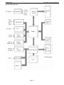
1
CPR-30201
Rack Mount LCD Keyboard Drawer
20.1” UXGA LCD
Four Port aRGB KVM
Technical Reference
Revision A
Warranty
The product is warranted against material and manufacturing defects for two years from
date of delivery. Buyer agrees that if this product proves defective Chassis Plans’ is only
obligated to repair, replace or refund the purchase price of this product at Chassis Plans’
discretion. The warranty is void if the product has been subjected to alteration, neglect,
misuse or abuse; if any repairs have been attempted by anyone other than Chassis Plans;
or if failure is caused by accident, acts of God, or her causes beyond the control of Chassis
Plans. Chassis Plans reserves the right to make changes or improvements in any product
without incurring any obligation to similarly alter products previously purchased.
In no event shall Chassis Plans be liable for any defect in hardware or software or loss or
inadequacy of data of any kind, or for any direct, indirect, incidental or consequential
damages arising out of or in connection with the performance or use of the product or
information provided. Chassis Plans’ liability shall in no event exceed the purchase price
of the product purchased hereunder. The foregoing limitation of liability shall be equally
applicable to any service provided by Chassis Plans.
Return Policy
Products returned for repair must be accompanied by a Return Material Authorization
(RMA) number, obtained from Chassis Plans prior to return. Freight on all returned items
must be prepaid by the customer, and the customer is responsible for any loss or damage
caused by common carrier in transit. Items will be returned from Chassis Plans via
Ground, unless prior arrangements are made by the customer for an alternative shipping
method
To obtain an RMA number, call us at 858-571-4330. We will need the following
information:
Return company address and contact
Model name and model # from the label on the back of the display
Serial number from the label on the back of the display
Description of the failure
An RMA number will be issued. Mark the RMA number clearly on the outside of each box,
include a failure report for each board and return the product(s) to our San Diego, CA
facility:
Chassis Plans.
8295 Aero Place
Suite 200
San Diego, CA 92123
Attn: Repair Department
Trademarks
Liability
Disclaimer
IBM, PC/AT, VGA, EGA, OS/2 and PS/2 are trademarks or registered trademarks of
International Business Machines Corp.
Intel is a registered trademark of Intel Corporation.
MS-DOS and Microsoft are registered trademarks of Microsoft Corp.
All other brand and product names may be trademarks or registered trademarks of their
respective companies.
This manual is as complete and factual as possible at the time of printing; however, the
information in this manual may have been updated since that time. Chassis Plans
reserves the right to change the functions, features or specifications of their products at
any time, without notice.
Copyright © 2007 by Chassis Plans. All rights reserved.
E-mail: [email protected]
Web: www.chassisplans.com
Chassis Plans
8295 Aero Place • San Diego, CA 92123
Phone: (858) 571-4330 • Fax: (858) 571-6146 • Email: [email protected]
Chassis Plans
CPR- 30201 Technical Reference
Table of Contents
Description ..................................................................................................................................1
Outline Drawing .....................................................................................................................2
Part Number Matrix.....................................................................................................................3
Keyboard Selection Options......................................................................................................3
Keyboard Options .....................................................................................................................3
Installation...................................................................................................................................4
Connecting the Display .............................................................................................................5
Picture-In-Picture (PIP) .............................................................................................................6
Front Panel Controls .................................................................................................................7
Sleep Mode ...............................................................................................................................8
OSD..............................................................................................................................................9
OSD Menu Organization ...........................................................................................................9
Display Menu ..........................................................................................................................10
PIP Menu ................................................................................................................................11
PIP More Setting Sub Menu ................................................................................................11
OSD Menu ..............................................................................................................................12
Audio Menu .............................................................................................................................12
Misc Menu...............................................................................................................................13
Misc. Zoom Sub Menu.........................................................................................................13
Misc. More Options Sub Menu ............................................................................................14
Video Controller Details ...........................................................................................................15
Features..................................................................................................................................15
General Description ................................................................................................................15
Controller Block Diagram ........................................................................................................16
Video Mode Support ...............................................................................................................17
Specifications ...........................................................................................................................18
Enclosure ................................................................................................................................18
Display ....................................................................................................................................18
Display Resolution ..................................................................................................................18
On Screen Display ..................................................................................................................18
Keyboards ...............................................................................................................................18
Regulations .............................................................................................................................18
Connectors:.............................................................................................................................19
Power Consumption................................................................................................................19
Environmental .........................................................................................................................19
Shipping ..................................................................................................................................19
Chassis Plans
CPR- 30201 Technical Reference
KVM Reference .....................................................................................................................20
Conventions ............................................................................................................................20
Introduction...............................................................................................................................21
Overview .................................................................................................................................21
Features..................................................................................................................................22
Hardware Requirements ............................................................................................................22
Console ..................................................................................................................................22
Computer ................................................................................................................................22
Hardware Setup ........................................................................................................................24
KVMS-RGBA4 Rear View ......................................................................................................24
Cable Connection....................................................................................................................25
Hot Plugging ...........................................................................................................................27
Hotkey Operation......................................................................................................................28
Port Switching .........................................................................................................................28
Cycling Through the Ports ...................................................................................................28
Going Directly to a Port .......................................................................................................29
Auto Scanning.........................................................................................................................29
Hotkey Setting Mode (Invoking HSM) ....................................................................................30
Alternate HSM Invocation Keys...............................................................................................30
Alternate Port Switching Keys .................................................................................................31
Keyboard Operating Platform..................................................................................................31
List Hotkey Settings ................................................................................................................32
USB Reset ..............................................................................................................................32
Hotkey Beeper Control............................................................................................................32
Disable Port Switching Keys ...................................................................................................32
Restore Default Settings .........................................................................................................33
HSM Summary Table..............................................................................................................33
Keyboard Emulation.................................................................................................................34
Sun Keyboard .........................................................................................................................34
Mac Keyboard.........................................................................................................................35
Firmware Upgrade Utility .........................................................................................................36
The Firmware Upgrade Utility .................................................................................................36
Before You Begin ....................................................................................................................36
Starting the Upgrade ...............................................................................................................37
Upgrade Successful ................................................................................................................38
Upgrade Failed........................................................................................................................38
Appendix ...................................................................................................................................39
KVM Specifications .................................................................................................................39
Troubleshooting ......................................................................................................................40
Chassis Plans
CPR-30201 Technical Reference
Description
The CPR-30201 is an ultra high performance rack mount 1U 20.1" TFT LCD display with UXGA 1600x1200
resolution. The display offers 250nit brightness, 500:1 contrast, and 89 degree viewing angle for exceptional
viewability. An anti-glare hard coating minimizes reflections making images that much clearer. The aspect ratio is
4:3 with a Pixel Pitch of only 0.255mm. It will display 16.7 million colors (True Color 32-bit).
With only 30” of depth, the CPR-30201 is perfect for rack or transit case installations. It can be used in Industrial,
Commercial, Military, or Broadcast applications. Its lightweight but rugged aluminum construction makes it perfect
for mobile installations. A ruggedized version with enhanced rack retention is offered for severe environments.
A variety of keyboards can be installed offering trackball or Glidepoint mouse functions. A Sun Microsystems Type
5 Compatible keyboard provides all Sun function keys. A NEMA-4 keyboard with integrated pressure sensitive
pointing device can be used in wet environments where chemicals or liquids may be spilled on the keyboard.
Multiple language support is available.
The CPR-30201 provides multiple signal input options including aRGB, DVI-D, NTSC, Pal S-Video and Composite
Video. Picture-In-Picture is supported with OSD control of the source. A KVM providing four channels of aRGB
switching is mounted to the rear.
As with all Chassis Plans products, a wide variety of custom options are available including paint color, customer
logo, transmissive daylight modification, hard coated vandal shields.
ENCLOSURE
20.1” UXGA 1600x1200 TFT LCD
1U (1.71”) x 30” deep
Rugged all aluminum construction
Designed to Satisfy Military, Industrial and
Commercial Requirements
Compact Enclosure for Limited Depth Installation
Speakers Mounted in Front Panel
DISPLAY
Largest LCD Panel that can fit within the standard
rack constraints in 1U.
20.1” Diagonal Active Matrix UXGA TFT LCD
Features LG Technology
1600 x 1200 @ 60Hz Native Resolution
89 deg Viewing Angle
500:1 Contrast Ratio
250cd/m2 Brightness
VIDEO CONTROLLER
Standard aRGB, DVI-D, S-Video and Composite
Video Inputs
OSD (On Screen Display) for Monitor Setup and
Control
Picture-in-Picture
Audio Input and Output with Built-In Amplifier
KEYBOARD
Several options including Sun and Nema 4, trackball
or Glidepad
OPTIONAL FEATURES / OPTIONS
Transflective LCD for Daylight Use
Enhanced Backlighting
Protective Glare Filters
Customer Specified Paint Color
Customer Logo
Page 1
Chassis Plans
CPR-30201 Technical Reference
Outline Drawing
Page 2
Chassis Plans
CPR-30201 Technical Reference
Part Number Matrix
CPR-30201-K where ‘K is the keyboard model shown below
Keyboard Selection Options
‘K’
1U
4U
5U
6U
8U
Keyboard Style
Cherry 83 Key
Cherry 83 Key
Nema 4
Sun
Nema 4 – 113 Key
Pointing Device
Trackball
Glide Point
Pressure Sensitive Pointing Device
Trackball
Hula Point
Keyboard Options
1U - USB
4U - USB
5U - USB
6U - USB
8U - USB
Cherry 83 key Keyboard with high quality 16mm integrated
trackball and two button pointing device. Featuring:
Mechanical keys with gold crosspoint contacts for highprecision key action, Individual key life expectancy
approximately 20 million cycles and a MTBF of 134,000
hours. Multiple language support available.
Cherry 83 Key Keyboard with high quality Integrated Cirque
Glidepad allows full mouse functionality. Featuring:
Mechanical keys with gold crosspoint contacts for highprecision key action, Individual key life expectancy
approximately 20 million cycles and a MTBF of 134,000
hours. Multiple language support available.
Nema 4 with integrated Pressure Sensitive Pointing Device
from Staco Switch. This keyboard was designed for rugged
duty computer applications where clean environments must
be maintained. This keyboard features a wipeable surface,
allowing for easy removal of dust, dirt, chemicals or foreign
matter. All keys are evenly backlit. Can be viewed while
wearing Night Vision Goggles.
Sun Microsystems Type 5 Compatible , 101 to 105 Key
(depending on Language Variant) Keyboard with high
quality 25 mm integrated trackball and three button pointing
device. Featuring: Individual Key Life expectancy
approximately 50 million cycles and a MTBF of 55,000
hours.
Nema 4 industrial 113 Key Keyboard with integrated
HulaPoint pointing device comes with 20 Function Keys, a 10Key Number pad and is made of industrial silicone rubber. It
has an operating temperature range of -40F to 194F (-40C to
90C) and a MTBF Greater than 10 Million Cycles. It can be
ordered in MS Windows or SUN configurations.
Page 3
Chassis Plans
CPR-30201 Technical Reference
Installation
To mount the CPR-30201 in a rack, it is first important you identify the correct holes to mount to. Please see the
following illustration. Note that a ‘U’ starts between the holes that are ½” apart. One very common problem is
trying to install into the wrong holes.
For most rack mount equipment, you can install the fixed rails in the rack and then slide the chassis into those rails.
However, the CPR-30201 is an integrated unit and must be installed completely assembled. This is much easier if
two people do the installation, one in front and one in back.
Because there are multiple styles of racks, we can’t provide detailed instructions on mounting the equipment.
However, there are general instructions at http://www.chassis-plans.com/PDF/Rack_Slide_Use.pdf for rack
installation which should help.
Rack Mounting Hole Spacing
The rack ears are widely adjustable. The display depth is 30.25” plus connectors. The ears provide for 2 10-32
screws on each ear.
Page 4
Chassis Plans
CPR-30201 Technical Reference
Connecting the Display
The CPR-30201 provides for analog, digital, composite and S-Video video inputs as well as connections for the
keyboard and mouse, and audio input and output. The CPR-30201 with KVM provides connectors mounted to the
rear of the system and includes 72” cables that connect to the user equipment. Optional cable lengths, connectors,
markings, etc. are available on special order.
Legend
Function
Connector
Audio L / Audio R
Audio Inputs for CVS and S-Video
RCA Plugs
CVI
Composite Video Input (CVS)
Recessed BNC.
S-Video
S-Video Input
4-Pin Mini Din
CPU1-4
aRGB Inputs to KVM plus Audio In/Out
Custom HD15 w/ 3.5mm Female Mini Stereo
Jacks
(See Note 1 Below)
aRGB Console
KVM Output – Loop Back to Display
HD15 w/ 3.5mm Female Mini Stereo Jacks
(See Note 2 Below)
F/W Upgrade
KVM Firm Ware Upgrade
RJ45 (See Note 3 Below)
USB
USB Output
USB Connector – Type A
(See Note 4 Below)
DVI-D
DVI-D Video Input
DVI-D Connector
15VDC
Power Input, 15VDC
2-Pin 2x5.5mm Power Plug Receptacle
Not Marked
aRGB Video and Sound Input to Display
from KVM
HD15 and 3.5mm Male Mini Stereo Plug
Video and Audio Connections
Note 1 – The CPR-30201 with KVM provides for connecting to four separate computers using the included
cables. Plug the Gold end of the cable with the Green and Red Audio Connectors into the
appropriate CPU1 through CPU4 connector on the rear of the CPR-30201. The computer end of
the cable provides a Blue HD15 connector for video, a Type A USB connector for the
trackball/touch pad (mouse input) and Red and Green audio connectors. The CPR-30201 does
not provide a microphone but provision is made on the rear of the display for a user provided
microphone to be connected to the Red Audio Connector in the aRGB Console area.
Note 2 – The output from the KVM is available at the aRGB Console connectors, outlined in Gold paint.
The two cables protruding from the right on the rear panel provide aRGB Video Input and Audio
Input to the display. These cables should be connected to the appropriate connectors in the
aRGB Console area.
Note 3 – The KVM provides for a Firm Ware upgrade using a special serial cable provided with the
display. Please see the appropriate area of the KVM section of this manual for instructions.
Leave the small switch in the Normal (right) position for operation.
Note 4 – The KVM provides two USB ports on the rear of the display. These USB ports are connected to
the selected CPU (1-4) when connected via the KVM. These USB ports can be connected by
the user to any USB compatible device.
Page 5
Chassis Plans
CPR-30201 Technical Reference
Rear Panel Signal Connectors
Cable Display End
Cable Computer End - USB
The CPR-30201 provides a front panel Source selection button for selecting which input signal is to be displayed.
In addition, Picture-In-Picture is supported where the S-Video or Composite video inputs can be displayed as a
small window on top of the aRGB or DVI-D inputs.
An audio amplifier is provided with a computer input source and 2 RCA audio inputs for right and left channel. The
front of the display provides two speakers connected to the audio amplifier. The audio channel can be selected via
the OSD for the computer input or the RCA video input (PIP). There is no provision to output sound from one RCA
input source to both speakers.
The KVM provides switching only for the aRGB inputs. The DVI-D, Composite and S-Video inputs are connected
directly to the display.
Picture-In-Picture (PIP)
The CPR-30201 supports PIP. The PIP window can be sized to Small (approx 1.4x2.0”), Medium (2.9x4.0”) or
Large (4.3x5.6”). There are 5 preset PIP window positions or the window can be moved to a user selected position
through the OSD menus. The PIP window is used to put a smaller video feed window on top of a full computer
display. The PIP button on the front panel can be used to select the video feed to display and the size.
The PIP source can only be S-Video or Composite input on top of either aRGB or DVI-D. The display will not use
either the aRGB or DVI-D as a PIP source. Setting the primary input to either Composite or S-Video disables the
PIP function.
The PIP window turns off when the monitor enters sleep mode, is turned off with the front Power control or is
stowed flat into the rack. To re-establish the PIP window, press the PIP button on the front panel and select the
desired input source and size using the + or – buttons.
Note
The default PIP source is TV. Whenever PIP is disabled by turning off the monitor or entering sleep
mode, the PIP input source will revert back to TV. After pressing PIP on the front panel, push either the
▲ or ▼ buttons to change to the PIP input selection Quick Menu and then + or ─ to change to the
desired input source.
Page 6
Chassis Plans
CPR-30201 Technical Reference
Front Panel Controls
The On Screen Display (OSD) is adjusted as follows:
1.
2.
3.
4.
Press the Menu Button located on the front of the monitor.
Use the buttons described below to maneuver around the Menu.
Select the desired OSD Menu from the Menu Screen Shots below to make the desired adjustment(s).
Press the Menu Button to exit out of the OSD Menu when complete or wait for the OSD window to
automatically close as set by the OSD Time Out setting.
•
•
•
•
•
•
•
•
Power: Turns the Unit On and Off
Menu/Exit: Enters and Exits the
menu and sub menus (Press
once to enter main menu,
press again to enter a sub
menu, press again to exit.
PIP: Brings up the Picture-In-Picture
Function Menu without having
to enter the Menu Key.
(▼) Arrow Down: Moves you Down
in the displayed menu
(▲) Arrow Up: Moves you Up in
the displayed menu
(─) Minus Sign: Decreases a
Function Level (Moves you
Left in the displayed menu).
(+) Plus Sign: Increases Function
Level (Moves you Right in the
displayed menu).
Source: Scrolls through the
different video sources.
Includes aRGB (VGA), DVI-D,
CVBS (Composite), SVHS (SVideo), TV (not available).
Quick Menu’s
A Quick Menu pops up by touching a single button. For
example by touching the minus button you bring up the
Volume’s Quick Menu and subsequently can adjust the Monitor
Volume level without have to go through the Main Menu, then
scrolling to the Volume Tab, moving to the Volume Level and
then making the adjustment.
Picture in picture Quick
Menu.
PIP: Brings up the PIP Menu
(V) Down Arrow: Toggles
between PIP source and
PIP On/Off/Size
(-) Minus Sign: Moves your
selection of Source or
Size Backward
(+) Plus Sign: Moves your
selection of Source or
Size Forward
Volume Quick Menu
(+) Brings up the Menu and
increases volume level
(-) Brings up the Menu and
decreases the volume
level
Display Auto Adjust
Pressing (+) and (-)
simultaneously will perform a
auto display adjustment
when in aRGB mode.
Front Panel Controls
To save your changes, press the front panel Menu/Exit button. Alternatively, changes are saved if no buttons are
pressed and the OSD times out returning back to the display.
There is a Factory Reset function under the Misc Adjustments Menu should you completely screw things up and
want to start over. See the right most Misc tab, More Options sub menu, Factory Reset.
Note – Pressing Source with the OSD displayed will over-ride the OSD and change the input source. Source
scans, in order, aRGB, DVI-D, TV, CVBS, SVHS. It is normal for the display to hang in the SVHS mode
while trying to change the source as the controller scans available SVHS modes. When a valid signal is
detected, a small window above the source indicator will display the resolution, frequency, and controller
mode.
Page 7
Chassis Plans
CPR-30201 Technical Reference
Sleep Mode
The display will enter sleep mode (turn off) if there is no input signal to the selected input mode. The delay to enter
Sleep Mode when the signal is not valid is approximately 6 seconds. When in sleep mode, the Power LED will
flash green. Pressing the Power button or Source button will exit the Sleep Mode and the display will scan the
selected input port for a signal. If no signal is present, the display will once again enter Sleep Mode. Note that
having a signal present on another port will not prevent the display from going into Sleep Mode if no signal is
present on the selected port. The display will only scan the selected port and does not auto-scroll through the other
ports.
Note that you can bring up the OSD menu when the display is brought out of Sleep Mode port but the OSD will
disappear when the display again enters Sleep Mode after not finding a signal.
Entering Sleep Mode will disable the PIP and revert to a TV PIP default. Use the front panel PIP to select the PIP
source and size to again display the PIP window. Alternatively, use the OSD to enable PIP.
Page 8
Chassis Plans
CPR-30201 Technical Reference
OSD
The CPR-30201 provides for On Screen Display (OSD) of the controls to adjust the display parameters such as
brightness, contrast, etc. The menus are context sensitive in that there are adjustments specifically for each
Source Input type (analog aRGB, digital DVI-D, S-Video and Composite). This allows you to tune the display for
each type of input without having to retune when changing the Source selection. The display controller stores the
settings in non-volatile memory so they are saved even when power is turned off or removed.
In the following menus, there are many common features and selections between each type of input. However,
some adjustments may not pertain to a particular input signal type so those adjustments are not shown.
Note
The display controller provides a TV function which is not utilized in theCPR-30201. While the TV
menu selections are available in the OSD, none of the TV functions work. Adverse display
behavior may be observed if the TV settings are changed and it is advised they be left set to the
default setting.
OSD Menu Organization
While different adjustments are available for each of the different input types, the menus are similarly organized
and the adjustments have the same effect.
Display Brightness (Fine and Course), Contrast, Phase, Frequency, H Position, V Position
PIP
Brightness, Contrast, Sharpness, Color, Tint, PIP Source, PIP Size, PIP More Settings (sub menu)
PIP More Settings – H Position, V Position, PIP Position Preset
OSD
OSD Background, OSD Time Out, OSD Position Preset, OSD H Position, OSD V Position, OSD
Language, Controller Firmware Revision
Audio
Volume, Treble, Bass, Balance, Audio Preset, Mute, Sound Swap
Misc.
Auto Adjustment, Source, Sleep Time, Sleep Time Remaining Indicator, Room Lighting, Freeze Frame,
Zoom Settings (sub menu), More Options (sub menu)
Zoom Settings – Zoom, Zoom H Pan, Zoom V Pan
More Options – Color Temp, Sharpness Filter, Scale Mode, Factory Reset
Note
An additional TV tab will display on the right if TV is selected for the Main Source or PIP Source.
It is recommended that TV not be selected or used for any adjustment.
Page 9
Chassis Plans
CPR-30201 Technical Reference
A typical menu appears as follows:
Display Menu
Adjustment
Brightness – Fine
Brightness – Course
Contrast
Phase
Frequency
H Position
V Position
Sharpness
Color
Tint
Brightness
Contrast
Phase
Frequency
H Position
V Position
Sharpness
Color
Tint
aRGB
●
●
●
●
●
●
●
Applicability
DVI-D
CVHS
●
●
●
●
●
●
●
●
●
CVBS
●
●
●
●
●
●
Top is Fine Adjustment and bottom is Course Adjustment. Adjusts the brightness
of the screen. Image brightness (ADC for analog signals, PW for digital).
Adjusts distinction (Image noise clearness). Image contrast (ADC for analog, PW
for digital).
Adjusts the phase signal sample. Use it to fine tune to eliminate noise or
overlapping lines.
Adjusts horizontal size of the screen by increasing or decreasing number of picture
elements.
Shifts displayed image left or right.
Shifts displayed image down or up.
Adjusts the sharpness of the picture.
Adjusts the display color saturation of the screen. (Video only, TV not available).
Used to adjust the display hue adjustment of the screen. (Video only, TV not
available).
Page 10
Chassis Plans
CPR-30201 Technical Reference
PIP Menu
Adjustment
Brightness
Contrast
Sharpness
Color
Tint
PIP Source
PIP Size
PIP More Settings (sub menu)
Brightness
Contrast
Sharpness
Color
Tint
PIP Source
PIP Size
PIP More Settings
aRGB
●
●
●
●
●
●
●
●
Applicability
DVI-D
CVHS
●
●
●
●
●
●
●
●
CVBS
Adjusts the brightness of the PIP display.
Adjust distinction (Image noise clearness).
Adjusts the sharpness of the PIP display.
Adjusts the display color saturation of the PIP display. (Video only, TV not available).
Used to adjust the display hue adjustment of the screen. (Video only, TV not
available).
S-Video (SVHS) or Composite (CVS) (TV not available)
Small, Medium, Large, and Off.
See Below.
PIP More Setting Sub Menu
Adjustment
H Position
V Position
PIP Position Preset
aRGB
●
●
●
Applicability
DVI-D
CVHS
●
●
●
CVBS
H Position
Move the PIP from Left Edge (0) to Right Edge (100)
V Position
Move the PIP from Bottom Edge (0) to Top Edge (100)
PIP Position Preset Top Left, Top Right, Middle of Screen, Bottom Left, Bottom Right.
Note
The PIP menus are not available (tab not shown) when the primary input source is set to CVHS or CVBS.
Page 11
Chassis Plans
CPR-30201 Technical Reference
OSD Menu
Adjustment
OSD Background
OSD Time Out
OSD Position Preset
OSD H Position
OSD V Position
OSD Language
Version 29A 1.00
OSD Background
OSD Time Out
OSD Position Preset
OSD H Position
OSD V Position
OSD Language
Version 29A 1.00
aRGB
●
●
●
●
●
●
●
Applicability
DVI-D
CVHS
●
●
●
●
●
●
●
●
●
●
●
●
●
●
CVBS
●
●
●
●
●
●
●
Opaque or Translucent
Sets the time (5 to 60 seconds) the OSD will be displayed without any user input.
Top Left, Top Right, Middle of Screen, Bottom Left, Bottom Right
Move OSD from Left Edge (0) to Right Edge (100)
Move OSD from Bottom Edge (0) to Top Edge (100)
English, French, Italian, German, two Asian languages
LCD Controller Firmware Revision
Audio Menu
Adjustment
Volume
Treble
Bass
Balance
Audio Preset
Mute
Sound Swap
Volume
Treble
Bass
Balance
Audio Presets
Mute
Sound Swap
aRGB
●
●
●
●
●
●
●
Applicability
DVI-D
CVHS
●
●
●
●
●
●
●
●
●
●
●
●
●
CVBS
●
●
●
●
●
●
Adjusts the audio output level.
Adjusts the midrange tone of the audio output.
Adjusts the base tone of the audio output.
Adjusts audio output to Right or Left bias.
Select preset Treble and Base settings (User, Movie, News and Standard).
Silence audio output. Off allows sound output. On mutes the sound (sound off)
Change audio input source from Main PC Audio in to PIP.
Audio Notes:
1. Treble and Bass will be ‘grayed out’ and not adjustable when Audio Preset is set to Movie, News or
Standard.
2. Sound Swap is not available when CVHS or CVBS are selected as the input because PIP is disabled in
that configuration.
3. A video signal must be present at CVHS or CVBS for the video sound input to function. Connecting an
audio source to the either the Audio Left or Audio Right without a corresponding video input will not work.
4. Pressing the front panel + or – control will raise or lower the volume without invoking the OSD. There is no
front panel Mute control.
Page 12
Chassis Plans
CPR-30201 Technical Reference
Misc Menu
Adjustment
Auto Adjustment
Source
Sleep Time
Room Lighting
Freeze Frame
Zoom Settings (sub menu)
More Options (sub menu)
aRGB
●
●
●
●
●
●
●
Applicability
DVI-D
CVHS
●
●
●
●
●
●
●
●
●
●
●
CVBS
●
●
●
●
●
Automatically adjusts the screen resolution and sync to the incoming signal.
(aRGB Source Only)
Source
Selects the video input signal source (aRGB, DVI-D, S-Video, and Composite
Video).
Sleep Time
Adjust (5 to 120 minutes) to set a desired time for monitor to go to sleep.
Sleep Time remaining Indicates remaining time until monitor goes to sleep (Grayed out until sleep timer is
activated.
Room Lighting
Bright, Normal, Movie changes the display brightness slightly with Movie being
lowest.
Freeze Frame
Retains the image on the monitor, including PIP.
Zoom Settings Menu See Below
More Options Menu See Below
Auto Adjust
Misc. Zoom Sub Menu
Adjustment
Zoom
Zoom H Pan
Zoom V Pan
Zoom
Zoom H Pan
Zoom V Pan
aRGB
●
●
●
Applicability
DVI-D
CVHS
●
●
●
●
●
●
CVBS
●
●
●
Zooms into the center of the displayed image, including PIP. If the PIP is not
located at the center of the display, it will be zoomed off the edge and will no
longer be visible. The maximum zoom factor is approximately 16:1.
Pans the zoomed image left or right.
Pans the zoomed image up or down.
Notes:
1. Zoom H Pan and Zoom V Pan will be grayed out if Zoom is set to 0.
Page 13
Chassis Plans
CPR-30201 Technical Reference
Misc. More Options Sub Menu
Adjustment
Color Temp
Red Temp
Green Temp
Blue Temp
Sharpness Filter
Scale Mode
Factory Reset
Color temp
User color
Sharpness Filter
Scale Mode
aRGB
●
●
●
●
●
●
●
Applicability
DVI-D
CVHS
●
●
●
●
●
●
●
●
●
●
●
●
●
●
CVBS
●
●
●
●
●
●
●
Adjust the Red/Green/Blue bias for Color Temperature (5500K, 7500K, 9300K and
User). Default value is set at 7300K.
You can adjust red, green and blue setting for user Color Temperature (grayed out
unless Color Temp set to User).
Adjust the picture Sharpness (Normal, Sharp, Sharpest, Soft, and Softest).
Adjust the output image size from the image scalar to be larger, smaller or same
as the display device.
Fill All – fill screen.
Fill Aspect – fill screen but maintain aspect ratio.
One To One – display image in original size (no scaling).
Zoom – convert letterboxed video to full screen.
Anamorphic – Squeezes a 16:9 image into a 4:3 space. Available only for
video inputs.
Video Game Zoom – Zooms display in slightly to remove game borders.
Available only for video inputs.
Factory Reset – Resets all settings back to factor settings including OSD
Language to English. Press (+) to reset.
Page 14
Chassis Plans
CPR-30201 Technical Reference
Video Controller Details
Features
• State of the art high performance picture quality design
• Analog RGB / DVI / CVBS (x1) & SVHS (x1) with NTSC, PAL, SECAM /Audio input (x3) / TV / Remote
control / Speaker out (x1)
• Optional input combination, e.g., PC Monitor only, PC Monitor with TV
• Full CRT multi-sync monitor compatibility
• Multi-sync capability up to UXGA resolution @ 75Hz, compatible standard DOS, VGA, SVGA, XGA and
SXGA VESA timing
• Expand DOS, VGA, SVGA ,XGA and SXGA to full screen display
• True color (16.7M) data processing and display driving
• Single control operated & transparent On-Screen-Display (hereafter ‘OSD’) user interface
• Full control of all relevant display and interface parameters via OSD
• Multi language support
• VESA DDC1/2B compliant
• Compatible with VESA DPMS power saving modes
• +12VDC single power: 48watts AC/DC power adapter recommended.
• Operating temperature: 0 to 50°C
• The 3watt x 2 ch. @ 7 ohms audio capability with treble, bass, volume and mute control through either
OSD or remote controller.
• OSD & Power switch board
• Optional TV tuner : NTSC, PAL and SECAM
• LCD Voltage select on Board : 5.0V, Adapter V, 12V
General Description
The DIT201001C Controller is an advanced TFT LCD Monitor Control Board. This design enables a
full conventional CRT monitor and/or video & audio replacement with a large size Active Matrix LCD
module. It is suitable for video resolution up to UXGA @ 75Hz in all video modes, the full display area
of the module is used.
The DIT201001C Controller is designed to act as a full monitor and/or video & audio interface. Besides the
main functionality of an analog and digital video interface, also CVBS (x1), SVHS (x1) and
stereo audio amplifier with 4 inputs.
Page 15
Chassis Plans
CPR-30201 Technical Reference
Controller Block Diagram
Page 16
Chassis Plans
CPR-30201 Technical Reference
Video Mode Support
The CPR-30201 monitor can support any video mode within the following input constraints:
• Signal sample frequency with the input ≤ 80kHz
• Horizontal sync frequency between 30KHz and 60KHz.
The modes are detected when presented to the input and previous alignments for setup are automatically
recalled. A true multi-sync monitor emulation is implemented.
The factory preset supported modes include:
Notes:
1. All mentioned modes are non-interlaced. The maximum and minimum frame rates are determined
the by the TFT LCD.
2. Factory preset modes are overwritten by additional user alignments for automatic recall. At all times
it remains possible to recall the initial factory presets.
Video Mode Support
Page 17
Chassis Plans
CPR-30201 Technical Reference
Specifications
ENCLOSURE
1U x 19" (wide) x 30" (deep) (Not including connectors)
Fits 27”-36” Rack
Weight: 30lbs
Color: Powder coated black, light texture (Custom colors and logos available)
DISPLAY
LG.Phillips LM201U04 20.1" TFT LCD w/ antiglare hard coating
Display area: 408mm x 306mm
Display Colors: 16.7 Million
Response Time: 16mS
Viewing Angle: 89/89/89/89 deg
Contrast Ratio: 500:1 typical
Brightness: 250cd/m2 typical
Pixel Pitch: 0.255mm x 0.255mm
Power Management: EPA Energy Star, VESA DPMS
DISPLAY RESOLUTION
Max Resolution:
D-Sub: Analog UXGA 1600 x 1200 @ 75Hz
DVI: UXGA 1600 x 1200 @ 60Hz
Recommended Resolution: DVI UXGA 1600 x 1200 @ 60Hz
19 Display Modes VGA to UXGA
Horizontal Frequency: 15-80KHz Automatic
Vertical Frequency: 60-75Hz Automatic
ON SCREEN DISPLAY
Contrast
Brightness
Autosetting
Clock / Phase
Horizontal & Vertical Position / Expansion / OSD
Text & Graph Mode Selection
Color Temp
Recall
Audio Function
PIP Source
KEYBOARDS
A variety of keyboards can be installed offering trackball or Glidepoint mouse functions. A Sun Microsystems
Type 5 Compatible keyboard provides all Sun function keys. A NEMA-4 keyboard with integrated pressure
sensitive pointing device can be used in wet environments where chemicals or liquids may be spilled on the
keyboard.
REGULATIONS
FCC-A, CE
Optional UL, CSA, TUV
Page 18
Chassis Plans
CPR-30201 Technical Reference
CONNECTORS:
aRGB:
DVI-D:
Composite:
S-Video In:
Audio In:
PC Audio In:
Keyboard/Mouns:
DC Power In:
15-pin high density DB15
DVI-D 23-pin female
BNC
4-Pin Mini Din
RCA (x2)
3.5mm Stereo Mini Jack Male
USB
2-Pin 2x5.5 Power Plug
POWER CONSUMPTION
Normal: 60W (front LED Green)
Power Input: 100-240VAC, 50/60Hz 1.2A
Power Cord: Wall-outlet type or PC-outlet type
The power supply is a Sunny model STD-1504 or equivalent "brick" measuring 2.5"(W) x 1.2"(H) x 4.3"(L). The
output is 15VDC at 4.0A. The DC cord length is approximately 36".
ENVIRONMENTAL
Operating conditions:
Temperature: 0 to 50 deg C
Humidity:
10% to 90% non-Condensing
Altitude:
12,000 feet
Storage conditions:
Temperature: -25 to 60 deg C
Humidity:
5% to 95% non-Condensing
Altitude:
40,000 feet
SHIPPING
Weight: 39lbs
Shipping Box - 40” x 23” x 6”
Page 19
Chassis Plans
CPR-30201 KVM Technical Reference
KVM Reference
Conventions
This KVM manual uses the following conventions:
[ ] Indicates keys you should press. For example, [Enter] means to press the Enter key. If keys need to be
chorded, they appear together in the same bracket with a plus sign between them: [Ctrl+Alt].
1.
Numbered lists represent procedures with sequential steps.
• Bullet lists provide information, but do not involve sequential steps.
� Indicates movement through a series. For example, Start � Run means to open the Start menu, and
then select Run.
Indicates critical information.
Page 20
Chassis Plans
CPR-30201 KVM Technical Reference
KVM Introduction
Overview
The KVMS-RGBA4 represents a revolutionary new direction in KVM (Keyboard, Video, Mouse) Switches. The
KVMS-RGBA4 are dual function four Port KVM Switches combined with 2 Port USB Hubs. As KVM switches,
they allow users to access four computers from a single USB keyboard, USB mouse, and monitor console. The
KVMS-RGBA4 improves on previous designs by giving the user a choice of either transferring keyboard or mouse
data to the computers via a USB connection, or with the traditional PS/2 connection.
If a USB connection is used, the KVMS-RGBA4‘s integrated two-port USB hub is available to each of the
computers. This permits each computer to access any peripherals connected to the hub on a ‘one computer at a
time’ basis.
The KVMS-RGBA4‘s asynchronous switching feature allows independent switching of the KVM, USB hub, and
audio focus. If you wish, you can give one computer the KVM console focus, another the USB hub focus, while a
third has the audio focus. You can work on a spreadsheet on one computer, for example, while you print from a
second computer at the same time, thus eliminating the need to purchase separate USB hubs or peripheral
sharers.
Recognizing the increased importance of sound, the KVMS-RGBA4 is audio enabled. A single microphone can
provide audio input to each of the computers, and you can listen to the audio output of each computer on a single
set of speakers (on a one-at-a-time basis).
Setup is fast and easy; simply plug cables into their appropriate ports. There is no software to configure, no
installation routines, and no incompatibility problems. Since the KVMS-RGBA4 intercepts keyboard input directly, it
works on multiple operating platforms (PC compatible, Mac*, Sun*, etc.).
Since a single console manages all of the computers, the KVMS-RGBA4 installation: 1) eliminates the expense of
having to purchase separate console components for each computer; 2) saves all the space those extra
components would take up; 3) saves on energy costs; and 4) eliminates the inconvenience and wasted effort
involved in constantly moving from one computer to another.
* Mac and Sun computers must use the USB cable connection.
Page 21
Chassis Plans
CPR-30201 KVM Technical Reference
Features
•
•
•
•
•
•
•
•
•
•
•
•
Dual function KVM-USB switch
One console 4 computers and two additional USB devices
Dual interface support -PS/2 or USB keyboard and mouse data transport*
Independent (asynchronous) switching of KVM and peripheral USB ports
Fully compliant with the USB 1.1 specification -supports transfer rates of 1.5/12 Mbps
Computer selection via Hotkeys
Auto Scan Mode for monitoring all computers
Complete keyboard emulation for error free booting
Superior video quality -2048x1536; DDC2B
Easy installation -no software required
Hot pluggable -add or remove computers for maintenance without powering down the switch
Supports Windows, Mac, and Sun host systems
Windows 98SE / ME / 2000 / XP; Mac OS8.6 or higher; Solaris; Linux
For PC compatible computers. Mac and Sun computers must use the USB cable connection.
Hardware Requirements
Console
A VGA, SVGA, or Multisync monitor capable of the highest resolution that you will be using on any
computer in the installation.
A USB style mouse
A USB style keyboard
Computer
The following equipment must be installed on each computer:
A VGA, SVGA or Multisync card.
Type A USB port, or PS/2 keyboard and mouse ports.
Page 22
Chassis Plans
CPR-30201 KVM Technical Reference
Cables
Only C50X and C60X Custom cable sets specifically designed to work with this switch may be used to link to
the computers. Four 1.2m 4-in-1 cable sets are provided with this package. They use the USB to transfer the
keyboard and mouse input from your console to the computer.
The switches also support computers that use PS/2 connectors to transfer keyboard and mouse data. Cable
sets with PS/2 connectors, as well as longer cable sets are also available:
Connector
USB
USB
PS/2
PS/2
Cable
Length
4 Feet
(1.2m)
6 Feet
(1.8m)
4 Feet
(1.2m)
6 Feet
(1.8m)
Part Number
KVMS-C504
KVMS-C604
Note: KVMS-RGBA4s USB hub function only
works with USB cable set connections. It will not
work with PS/2 cable set connections.
KVMS-C606
For additional cables, contact Chassis Plans.
KVMS-C506
Page 23
Chassis Plans
CPR-30201 KVM Technical Reference
Hardware Setup
KVMS-RGBA4 Rear View
1. Console Audio Jacks
The cables from your microphone and speakers plug in here. Each jack is marked with an appropriate
icon to indicate itself.
2. USB Hub Section
USB peripherals (printers, scanners, etc.) can plug into any available port.
3. Firmware Upgrade Section
Firmware Upgrade Switch
During normal operation this switch should be in the NORMAL position.
Firmware Upgrade Port The Firmware Upgrade Cable that transfers the firmware upgrade data from the
administrator’s computer to the KVMS-RGBA4 plugs into this RJ-11 connector.
4. Monitor Port
The video cable from your monitor plugs in here.
5. CPU Port Section
The cables that link the switch to your computers plug in here. Each CPU port is comprised of a
microphone jack, speaker jack, and KVM data connector.
Note:
The shape of these 15-pin connectors has been specifically modified so that only KVM cables designed
to work with this switch can plug in (see the Cables section, for details). Do NOT attempt to use
ordinary 15 pin VGA connector cables to link these ports to the computers.
Page 24
Chassis Plans
CPR-30201 KVM Technical Reference
Before you Begin
1. Make sure that power to all the devices you will be connecting up have been turned off.
2. To prevent damage to your installation make sure that all devices on the installation are properly grounded.
Cable Connection
To set up your KVMS-RGBA4 installation, refer to the installation diagrams on the following pages, and do the
following:
1. Plug your monitor into the Console monitor port located on the unit’s rear panel.
2. Plug your microphone and speakers into the Console microphone and speaker jacks located on the unit’s
rear panel.
3. Using a KVM cable set (provided with this package), plug the custom SPDB connector into any available
CPU Port on the switch and plug the accompanying microphone and speaker cables into the CPU Port’s
microphone and speaker jacks.
Note:
Be sure that all the plugs are in the same CPU Port sockets (all in Port 1, all in Port 2, etc.).
4. At the other end of the cable:
a) For a USB connection, plug the USB, video, microphone and speaker cables into their respective
ports on the computer.
b) For a PS/2 connection, plug the keyboard, mouse, video, microphone and speaker cables into their
respective ports on the computer. Repeat steps 4 and 5 for any other computers you are
connecting up.
5. Turn on the power to the computers.
Rear Panel Connections
Page 25
Chassis Plans
CPR-30201 KVM Technical Reference
USB Cable Connection
PS/2 Cable Connection
Page 26
Chassis Plans
CPR-30201 KVM Technical Reference
Hot Plugging
The KVMS-RGBA4 supports USB hot plugging. Components can be removed and added back into the installation
by unplugging their cables from the CPU ports without the need to shut the unit down.
Powering Off and Restarting
If it becomes necessary to Power Off the KVMS unit, before starting it back up you must do the following:
1. Shut down all the computers that are attached to the switch.
Note:
You must unplug the power cords of any computers that have the Keyboard Power On function that are
connected to the shut down switches. Otherwise, the switches will still receive power from the computers.
2. Unplug the switch’s power adapter cable.
3. Wait 10 seconds, then plug the switch’s power adapter cable back in.
4. After the switch is up, Power On the computers.
Port Numbering
Each CPU port on the KVMS-RGBA4 switch is assigned a port number 1 to 4. The port numbers are marked on
the rear panel of the switch.
The Port ID of a computer is derived from the CPU port number it is connected to. For example, a computer
connected to CPU port 3 has a Port ID of 3.
The Port ID is used to specify which computer gets the KVM, USB hub, and audio focus with the Hotkey port
selection method.
Page 27
Chassis Plans
CPR-30201 KVM Technical Reference
Hotkey Operation
The KVMS-RGBA4 provides an extensive, easy-to-use, hotkey function that makes it convenient to control and
configure your KVM installation from the keyboard. Hotkeys provide asynchronous (independent) switching of the
KVM, USB hub and audio focus. If you wish, you can give one computer the KVM console focus, another the USB
hub focus, while a third has the audio focus.
Port Switching
All port switches begin with tapping the Scroll Lock key twice. The tables below describe the actions that each
combination performs.
Note:
If using the Scroll Lock key conflicts with other programs running on the computer, the Ctrl key can be
used, instead.
Cycling Through the Ports
Hotkey
[ScrollLock][ScrollLock][Enter]
Action
Brings the KVM, USB hub, and audio focus
from the port that currently has the KVM
focus to the next port on the installation. (1
to 2; 2 to 3; 3 to 4; 4 to 1)
[ScrollLock][ScrollLock][K][Enter]
[ScrollLock][ScrollLock][U][Enter]
[ScrollLock][ScrollLock][n][S][Enter]
Note that the KVM, USB hub, and audio
focus all go to this port even if they were on
different ports to begin with.
Brings only the KVM focus from the port that
currently has it to the next port on the
installation. The USB hub and audio focus
remain where they are.
Brings only the USB hub focus from the port
that currently has it to the next port on the
installation. The KVM and audio focus
remain where they are.
Brings only the audio focus from the port
that currently has it to the next port on the
installation. The KVM and USB hub focus
remain where they are.
Page 28
Chassis Plans
CPR-30201 KVM Technical Reference
Going Directly to a Port
Hotkey
Action
Brings the KVM, USB hub, and audio
focus to the computer attached to the
port corresponding to the specified Port
ID.
[ScrollLock][ScrollLock][n][Enter]
[ScrollLock][ScrollLock][n][K][Enter]
[ScrollLock][ScrollLock][n][U][Enter]
[ScrollLock][ScrollLock][n][S][Enter]
[ScrollLock][ScrollLock][n][K][U][Enter]
[ScrollLock][ScrollLock][n][K][S][Enter]
[ScrollLock][ScrollLock][n][U][S][Enter]
Note:
Note that the KVM, USB hub, and audio
focus all go to this port even if they
were on different ports to begin with.
Brings only the KVM focus to the
computer attached to the specified port.
The USB hub and audio focus remain
where they are.
Brings only the USB hub focus to the
computer attached to the specified port.
The KVM and audio focus remain
where they are.
Brings only the audio focus to the
computer attached to the specified port.
The KVM and USB hub focus remain
where they are.
Brings the KVM and USB hub focus to
the computer attached to the specified
port. The audio focus remains where it
is.
Brings the KVM and audio focus to the
computer attached to the specified port.
The USB hub focus remains where it is.
Brings the USB hub and audio focus to
the computer attached to the specified
port. The KVM focus remains where it
is.
The n stands for the computer’s Port ID number (1, 2, 3, or 4-see Port Numbering). Replace the n with the
appropriate Port ID when entering hotkey combinations.
Auto Scanning
The KVMS-RGBA4‘s Auto Scan feature automatically cycles the KVM focus through the computer ports at regular
intervals. This allows you to monitor the computer activity without having to take the trouble of switching from port
to port manually. See the table below for details.
Note:
The n stands for the number of seconds that the KVMS-RGBA4 should dwell on a port before moving on to
the next. Replace the n with a number between 1 and 99 when entering this hotkey combination.
Page 29
Chassis Plans
CPR-30201 KVM Technical Reference
Hotkey Setting Mode (HSM)
Hotkey Setting Mode is used to set up your KVMS-RGBA4 switch configuration. All operations begin with invoking
Hotkey Setting Mode (HSM).
Invoking HSM
To invoke HSM do the following:
1. Press and hold down the Num Lock key
2. Press and release the minus key
3. Release the Num Lock key
Note:
1. There is an alternate key combination to invoke HSM. See below for details.
2. The minus key must be released within one half second, otherwise Hotkey invocation is canceled.
When HSM is active, the Caps Lock, and Scroll Lock LEDs flash in succession to indicate that HSM is in effect.
They stop flashing and revert to normal status when you exit HSM.
Ordinary keyboard and mouse functions are suspended -only Hotkey compliant keystrokes and mouse clicks
(described in the sections that follow), can be inputted.
At the conclusion of some hotkey operations, you automatically exit hotkey mode. With some operations, you must
exit manually. To exit HSM manually, press the Esc key, or the Spacebar.
Alternate HSM Invocation Keys
An alternate set of HSM invocation keys is provided in case the default set conflicts with programs running on
the computers.
To switch to the alternate HSM invocation set, do the following:
1. Invoke HSM (see above)
2. Press and release the H key The HSM invocation keys become the Ctrl key (instead of Num Lock)
and the F12 key (instead of minus).
Note:
This procedure is a toggle between the two methods. To revert back to the original HSM invocation keys,
invoke HSM, then press and release the H key again.
Page 30
Chassis Plans
CPR-30201 KVM Technical Reference
Alternate Port Switching Keys
The port switching activation keys can be changed from tapping the Scroll Lock key twice ([Scroll Lock] [Scroll
Lock]) to tapping the Ctrl key twice. To change the port switching activation keys, do the following:
1. Invoke HSM
2. Press and release the T key
Note:
This procedure is a toggle between the two methods. To revert back to the original [Scroll Lock] [Scroll
Lock] method, invoke HSM, then press and release the T key again.
Keyboard Operating Platform
The KVMS-RGBA4 ‘s default port configuration is for a PC Compatible keyboard operating platform. If your
requirements call for different port settings (you have a Mac or Sun attached to a port, e.g.), you can change a
port’s keyboard operating platform configuration as follows:
1. Bring the KVM focus to the port you want to set.
2. Invoke HSM
3. Press and release the appropriate Function key (see table). After completing a setting, you
automatically exit HSM.
* The first time that the Sun system runs from a port, you must configure its port for the Sun keyboard operating
platform before you turn the system on, or else the Sun system will not start.
Page 31
Chassis Plans
CPR-30201 KVM Technical Reference
List Hotkey Settings
To see a listing of the current hotkey settings, do the following:
1. Invoke HSM.
2. Press and release the F4 function key.
3. Open a text editor or word processor and use its Paste function to display the settings.
USB Reset
If the USB looses focus and needs to be reset, do the following:
1. Invoke HSM.
2. Press and release the F5 function key.
Hotkey Beeper Control
The Beeper can be hotkey toggled On and Off. To toggle the Beeper, do the following:
1. Invoke HSM.
2. Press and release the B key.
The Beeper toggles On or Off. The Command Line displays Beeper On or Beeper Off for one second; then the
message disappears and you automatically exit Hotkey Mode.
Disable Port Switching Keys
To disable the Port Switching Keys ([Scroll Lock] [Scroll Lock] / [Ctrl] [Ctrl]), do the following:
1. Invoke HSM.
2. Press [X] [Enter].
Note: This procedure is a toggle. To enable the Port Switching keys repeat steps 1 and 2.
Page 32
Chassis Plans
CPR-30201 KVM Technical Reference
Restore Default Settings
To reset the KVMS-RGBA4 to its default hotkey settings, do the following:
1. Invoke HSM.
2. Press [R] [Enter].
All hotkey settings return to the factory default settings.
HSM Summary Table
After invoking HSM, key in one of the following keys to perform the corresponding function:
Page 33
Chassis Plans
CPR-30201 KVM Technical Reference
Keyboard Emulation
Sun Keyboard
The PC compatible (101/104 key) keyboard can emulate the functions of the Sun keyboard when the Control
key [Ctrl] is used in conjunction with other keys. The corresponding functions are shown in the table below.
Note:When using [Ctrl] combinations, press and release the Ctrl key, then press and release the activation key.
Page 34
Chassis Plans
CPR-30201 KVM Technical Reference
Mac Keyboard
The PC compatible (101/104 key) keyboard can emulate the functions of the Mac keyboard. The emulation
mappings are listed in the table below.
Note:
When using key combinations, press and release the first key, then press and release the second one.
Page 35
Chassis Plans
CPR-30201 KVM Technical Reference
Firmware Upgrade Utility
The Firmware Upgrade Utility
The Windows-based Firmware Upgrade Utility (FWUpgrade.exe) provides a smooth, automated process for
upgrading the KVM switch’s firmware. The Utility comes as part of a Firmware Upgrade Package that is specific for
each device.
Before You Begin
5.
Choose the Firmware Upgrade Package you want to install (usually the most recent), and download it
to your computer.
Power off the switch.
Unplug the KVM cables from the back of the switch.
Use the Firmware Upgrade Cable provided with this unit, to connect a COM port on your computer to
the Firmware Upgrade Port of your switch
Slide the Firmware Upgrade Switch to the Upgrade position.
6.
Power the switch back on by plugging in the Unit. The Unit is now in Firmware upgrade Mode.
1.
2.
3.
4.
Page 36
Chassis Plans
CPR-30201 KVM Technical Reference
Starting the Upgrade
To upgrade your firmware:
1. Run the downloaded Firmware Upgrade Package file -either by double clicking the file icon, or by opening
a command line and entering the full path to it.
2. The Firmware Upgrade Utility Welcome screen appears:
Note:
The screenshots in this section are for example purposes. The screens that appear during your firmware
upgrade may vary slightly as to their wording and descriptions.
1. Read and Agree to the License Agreement (enable the I Agree radio button).
2. Click Next to continue. The Firmware Upgrade Utility main screen appears:
3. The Utility inspects your installation. All the devices capable of being upgraded by the package are
listed in the Device List panel.
4. As you select a device in the list, its description appears in the Device Description panel.
5. After you have made your device selection(s), Click Next to perform the upgrade. If you enabled Check
Firmware Version, the Utility compares the device’s firmware level with that of the upgrade files. If it
finds that the device’s version is higher than the upgrade version, it brings up a dialog box informing
you of the situation and gives you the option to Continue or Cancel.
Page 37
Chassis Plans
CPR-30201 KVM Technical Reference
If you didn’t enable Check Firmware Version, the Utility installs the upgrade files without checking whether they are
a higher level, or not. As the Upgrade proceeds status messages appear in the Status Messages panel, and
the progress toward completion is shown on the Progress bar.
Upgrade Successful
After the upgrade has completed, a screen appears to inform you that the procedure was successful.
To complete the upgrade:
1. Click Finish to close the Firmware Upgrade Utility.
2. Power off the switch by unplugging the KVM cable that you connected in step 6 of Before You Begin, from
the back of the switch.
3. Remove the Firmware Upgrade Cable.
4. Slide the Firmware Upgrade Switch to the Normal position.
5. Connect all the KVM cables.
6. If you are using a power adapter, plug its cable back in.
Upgrade Failed
If the Upgrade Successful screen doesn’t appear, it means that the upgrade failed to complete successfully, in
which case you should repeat the upgrade procedure from the beginning.
Page 38
Chassis Plans
CPR-30201 KVM Technical Reference
Appendix
KVM Specifications
Function
KVMS-RGBA4
Computer Connections
4
CPU Port Selection
Front Panel Switches; Hotkey
USB Port Selection
Console
Keyboard
Connectors
Mouse
Hotkey
Video
Audio
CPU
Connectors
KVM
data
Audio
1 x USB Type A (Integrated inside)
1 x USB Type A (Integrated Inside)
1 x HDB -15 female
1 x Stereo port 1 x Microphone port
4 x SPDB -15 female
4 x Stereo ports 4 x Microphone ports
USB Peripherals
2 x USB Type A
Firmware Upgrade
1 x RJ-11socket
Power Adapter
1 x DC 5V jack
Scan Interval
1 -99 secs. (5 secs. default)
Resolution
Up to 2048 x 1536
Power Consumption
1280mA
Operating Temperature
0 -50o C
Storage Temperature
-20 -60o C
Humidity
0 -80% RH
Page 39
Chassis Plans
CPR-30201 KVM Technical Reference
Troubleshooting
Symptom
Possible Cause
Action
Keyboard
and/or
Mouse not
responding.
Keyboard
and/or mouse
need to be
reset.
Press and hold port selection
switches 1 and 2 for two seconds
No connection
to the
computer.
Unplug the cable(s) from the console
port(s), then plug it/them back in.
Check the cable from the switch to
the computer to make sure it is
properly connected.
Power off all devices on the
installation; power off the KVM
switch; wait five seconds; then power
up.
Unplug the device’s USB cable from
the USB port on the switch’s rear
panel, then plug it back in.
Use the USB Reset hotkey
combination, to reset the USB ports.
1. Unplug the KVM cable from the
computer’s USB port.
KVM switch
needs to be
reset.
USB
devices not
responding.
Device not
recognized
message
(Windows)
USB ports need
to be reset.
Windows timing
problem.
2. Go into Windows’ System Settings
and remove the Unknown Device
entry.
Sun system
does not
start.
CPU port not
configured
correctly.
3. Plug the KVM cable back in.
Windows will now recognize the
device.
The first time that a Sun system runs
from a port, you must configure its
port for the Sun keyboard operating
platform before you turn the system
on, or else the Sun system will not
start.
Page 40