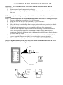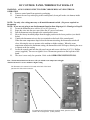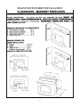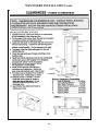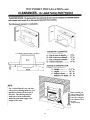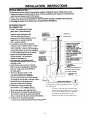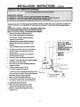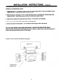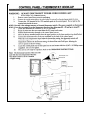
1
MAGNUM WINCHESTER
Corn/Biomass/Wood Pellet Stove
Models: WINACP, WINACI, WINDCI, WINDCP
Owner’s Manual
Installation – Operation – Maintenance Instructions
NOTE: THESE INSTRUCTIONS MUST BE SAVED for future reference
PLEASE READ THIS ENTIRE MANUAL BEFORE INSTALLATION AND USE OF THIS PELLET
BURNING STOVE. FAILURE TO FOLLOW THESE INSTRUCTIONS MAY RESULT IN PROPERTY
DAMAGE, BODILY INJURY OR EVEN DEATH.
IMPORTANT: Always contact your local MagnuM dealer/installer with questions before contacting the
factory. When you call, have your serial number, purchase date, who installed the unit and a list of
questions.
9 When installing your MagnuM Winchester (WIN) Corn/Biomass/Wood Pellet stove, particular attention
needs to be made in regards to fire protection. If the unit is not properly installed, a house fire may result.
For your safety, follow the installation and operation instructions provided, and if a question arises contact
local building or fire officials about restrictions and installation requirements in your area.
9 Read the operations and fuel section of this manual before plugging in your unit.
9 Always unplug the unit before attempting any service work.
9 Do not connect the unit to a chimney flue already serving another appliance.
9 When installing the chimney pipe to the unit, it is important to remember that the unit operates on a
negative pressure and the chimney on a positive pressure. All chimney connections, elbows and fittings
must be airtight. (Proper venting practices must be followed. Consult with a venting professional)
9 Ashes must be disposed of in a metal container with a tight fitting lid.
9 All minimum clearances to combustibles must be followed.
9 The MagnuM Corn/Biomass/Wood Pellet Stove is tested for operation with wood pellets, with an ash
content of no more than 2% and Corn with a moisture content from 10-14 percent. It is recommended
that wood pellets with an ash content of 1% or less be used for efficient operation of this unit. Higher
ash content fuels will require additional maintenance and service. Also, for use with wood pellets,
cherry pits, olive pits or other pelletized Biomass fuel. Corn with 11-12 percent moisture is ideal.
9 It is important to use fuel that is clean, dry and consistent. Make sure that your supplier is giving you
the same fuel each time that you purchase. It is recommended that you purchase your entire heating season
supply of fuel at one time so that the fuel will be the same.
9 A voltage surge protector or ground fault outlet is required for this unit. The electrical component
warranty will be voided if surge protection is not installed before operating this unit.
9 A grounded outlet must be provided with proper polarity. A constant 115 volt (12volt on DC
models), 60 cycles must be provided for proper operation or the warranty of this appliance will be
forfeited.
9 Special attention needs to be taken to clean out the top heat exchangers of this unit on a regular
basis. The fly ash settles on the heat exchangers and must be cleaned off to keep the unit operating
properly. Check for plugging every two-four weeks or when needed.
9 If unit is not operated for extended periods of time (like summer) unplug the unit and disconnect the
battery to assure long life of electrical components.
AMERICAN ENERGY SYSTEMS, INC. GRANTS NO WARRANTY, IMPLIED OR
STATED, FOR THE INSTALLATION OR MAINTENANCE OF THE STOVE AND
ASSUMES NO RESPONSIBILITY FOR ANY CONSEQUENTIAL DAMAGE(S).
AMERICAN ENERGY SYSTEMS, INC. - 150 Michigan Street SE - HUTCHINSON, MINNESOTA 55350
Web Site: www.MagnuMheat.com
date 07/9/07
SECTION
PAGE
Introduction/Specifications...……………………………………
Technical Bulletin/Importance of Adequate Fresh Air………….
Safety Steps………………………………………………………
Burning Solid Fuels………………………………………………
Unpacking Your MagnuM Wood Pellet Appliance …………….
Clearances………………………………………………………..
Guidelines for Exhaust Venting Systems Design………………..
Design Guidelines for Outside Combustion Air Connection…….
Installation Precautions…………………………………………..
Installation Configurations………………………………………..
Vent Termination General Instructions…………………………...
Horizontal Installation……………………………………….……
Vertical Installation……………………………………………….
AC/DC Control Panel/Thermostat Hook-up…..………………….
MagnuM WIN Insert Installation …………………………………
Installation Instructions……………………………………………
Control Panel/Thermostat Hook-up……………………………....
Optional 12 Volt Battery Back-up………………………………..
Operating Instructions AC/DC/All Models……………………….
Cleaning Instructions……………………………………………...
Cleaning Instructions for the Winchester Insert…………………..
Automatic Features………………………………………………..
Glass Maintenance, Adjustment, Removal and Replacement…….
Circuit Board Functions…………………………………………...
Setting the Draft…………………………………………………...
Wiring Diagram AC/DC.………………………………………….
Draft Slide Gate Adjustment………………………………………
Solar Panel Connections…………………………………………..
Igniter Replacement……………………………………………….
Trouble Shoot Guide...……………………………………………..
MagnuM Winchester Replacement Parts List…………………….
Warranty…………………………………………………………..
Service Record…………………………………………………….
3
4
5
6, 7
7, 8
9
10, 11
12
13
14
15
16
17, 18
19, 20
21, 22, 23
24, 25, 26
27
28
29, 30, 31
32, 33
34, 35
36
37
38, 39
40
41, 42
43
43
44
45, 46, 47, 48
49
50
51
TESTING/CERTIFICATION INFORMATION
The MagnuM WIN stove (report # 150-S-01b-4) independently tested in accordance with ASTM E1509
The MagnuM WIN Insert (report # 097-S-04-2) independently tested in accordance with ASTM E1509
Tested with OMNI-Test Laboratories, Inc, BEAVERTON, OREGON 97005
per EPA Method 28A, ULC C1482-M1990, CAN/ULC-S627-00, ULC-S628, APFI req.
The pellet fired appliance has been tested and listed for use in manufactured homes in accordance with
Oregon
Administrative Rules 814-23-900 through 814-23-909 (UM) 84-HUD
SERIAL #______________
DATE PURCHASED_______________
READ THIS MANUAL THOROUGHLY BEFORE INSTALLING THIS UNIT AND KEEP THIS
MANUAL IN A HANDY PLACE FOR FUTURE REFERENCE.
2
DEAR VALUED MAGNUM PRODUCT OWNER,
We appreciate your decision to help preserve our precious environment by purchasing your MagnuM
Corn/Biomass/Wood Pellet Appliance. With everyone working together, we can have clean air and
renewable heat for our homes.
Please read this Owners Manual carefully before using this appliance and if you have any questions contact
your local MagnuM dealer. We appreciate your business and wish you many warm days and nights with
your new MagnuM Corn/Biomass/Wood Pellet Appliance.
Sincerely,
Mike Haefner, President
American Energy Systems, Inc.
P.S. You are very important to the success of our business and your referral of our products is very much
appreciated. Many of our Resellers have referral rewards available and I encourage you to ask your local
dealer how to get involved in helping make our country energy self-sufficient. GOOD LUCK!
SPECIFICATIONS
American Energy Systems, Inc., manufacturer of the MagnuM Winchester Appliances, reserves the right to
alter its products, their specifications and/or price without notice.
Safety tested and EPA exemption tested by Omni to UL 1482, CAN/ULC-S627, ULC-S628, APFI
requirements, Oregon administrative rules 814-23-900 to 814-23-909 and E.P.A. Method 28A.
Winchester
Heating range
Insert
8,000- 40,000 BTU
Fuel Storage Capacity
Up to 68 Lbs.
Up to 60 Lbs.
Width
24”
23 1/2”
Height
33”ped,
Depth
22”
40”leg,
21 1/2”Insert
21 ½”
CLEARANCE TO COMBUSTIBLES, Stoves
Insert clearance to combustibles are on pages 21-24
Vertical Termination
w/3” Pellet Vent
3” (75mm)
Back Wall
Side
3” (75mm)
Corner
3” (75mm)
Flue to Wall
3” (75mm)
Floor Protection
6” (150mm) out in front of unit 6” to sides
BTU input will vary, depending on the brand of fuel, size of fuel, quality of fuel and moisture content.
Consult your authorized MagnuM reseller for information on the best fuel to use to get the best results.
Fuel feed rates can vary as much as 50 percent depending on fuel quality, size, brand and moisture content.
3
Technical Bulletin
Importance of Adequate Fresh Air
Every home is a slightly different situation and depending on the design of the air movement within
the home, might be easy to distribute heat or very difficult. If you have boiler heat or other nonducted central heating this becomes even more of a challenge as adequate circulation within the
home and proper make up air for combustion is lacking because of the design of your central
heating system.
When a forced-air system is put into a home that is not designed with proper circulatory patterns, it
might be necessary to add return air ducts or at least vents to get the air moving around the home.
Fresh air for the home and fresh air for combustion will have to be added or the stove or furnace
will burn dirty and efficiency will suffer.
Your dealer needs to assess the fresh air requirements for the home. At a minimum, there should be
a 6” or larger (this should be determined by figuring what the home requires) fresh air vent coming
in to a neutral part of the home to make sure that there is adequate fresh air to the home. Then the
3”make up air to the unit is required to be provided.
If the wood pellets are not burning correctly you need to address a few things. Are the wood pellets
wet or dirty? If they are, make sure that your wood pellets are cleaned (we have an excellent “ESIFTER” product that will do a great job) and below 15 percent moisture. 3-4 percent moisture is
ideal.
The most common cause of wood pellets not burning properly is contaminated air or negative
pressure in the home. It can be as simple as the air adjustment not set properly on the side of the
stove or it could be that there is a serious lacking of good quality air in the home caused by negative
pressure. If you have done any remodeling or if this is a newer home, it is a very real possibility
that this is happening. Most basements have negative pressure even if you feel that your home is
drafty. This is called the stack or chimney effect.
If there is a black coating of soot coming into the home it is caused by the reversal of the exhaust
that would normally exit the stove outside being drawn into the home by negative pressure or
improperly installed venting. Depending on your venting configuration this could be aggravated by
back drafts, high wind and cold chimneys.
Sometimes this also occurs if there is an intake for fresh air too close to the exhaust on the outside
of the home or other conditions causing the exhaust to be pulled back into the home.
The first indications of negative pressure affecting the stove occurs app. 3 days after the stove is lit.
The glass gets dirty very easy, the firepot might keep filling up even though you pull the air
adjustment out, and you notice that the venting fills up with soot rapidly. After a few days, the
exhaust can no longer adequately pull out all of the fly ash so it reverses and is pulled into the
home. This might happen through the venting if it is not sealed properly or it might come out when
you open the door for maintenance and also backwards through the air wash system.
This can be easily corrected by adding the fresh air for the home and also for the appliance. It is
imperative that you would have your dealer or installer check the unit out for proper operation to
make sure that there is nothing mechanical wrong with the appliance and then determine your need
for proper fresh air. Your dealer can contact the factory with any questions that he might have.
4
SAFETY STEPS
IMPORTANT: Proper installation of this stove is crucial for proper and safe operation. Installing this
product improperly may result in a house fire and/or personal injury. All applicable building codes for
your location must be followed. In areas where building codes require additional steps to the installation
of this product not included in this manual, the building codes will take precedent and must be followed.
Contact your local building inspector to obtain any necessary permits or inspection guidelines before
installing the product. (This appliance must be installed by a trained professional installer to assure
proper installation and warranty of this product) Warranty labor, parts failing due to improper
installation and shipping will not be covered if the unit is not installed by a trained installer.
9 DISCONNECT THE POWER CORD BEFORE SERVICING THIS STOVE! A power
surge protector is required. The unit must be plugged in to a grounded 110 volt 60 Hz or a 12V
DC sealed battery power source. NEVER use an “unsealed” type battery, nor operate unit on a
battery without a 12 volt 4 ampere in-line fuse on a positive line.
9 Always route the power cord away from the unit. Do not route cord in foot traffic areas. Do not
pinch cord under furniture. Do not add any additional length to the power cord.
9 This product requires simple periodic maintenance for proper operation and long life of the stove.
Read and follow the maintenance schedule closely. Do not operate with the doors or hopper
open.
9 The MagnuM Winchester stove models are designed, approved and tested to burn
corn/wood pellets and other Biomass fuels. The burning of other solid fuels such as cord wood
in this stove is not permitted. If you are burning fuels not approved for this appliance it will void
the warranty and no service/warranty will be allowed.
9 The MagnuM models will burn high ash content fuels but will require additional
maintenance/cleaning.
9 A working smoke detector must be installed in the same room as this product.
9 It is recommended that a fire extinguisher “class a-b-c” be installed close to the appliance.
9 Flammable or explosive liquids such as gasoline, naphtha or engine oil must NEVER be used in or
around this stove. These liquids must be stored well away from this stove as the open flame in the
burn chamber could ignite the fumes of such liquids. Do not burn garbage in this unit.
9 According to HUD requirements, when installed in a mobile home, this stove must be grounded
directly to the steel chassis of the mobile home and bolted to the floor.
9 This stove is not intended for use in commercial installations but can be used.
9 The moving parts of this stove are propelled by high torque electric motors. The auger can cause
severe injury to body parts that may get near them. Keep all body parts away from the auger while
the stove is plugged into an electrical outlet. These moving parts may begin moving at any time
while the stove is plugged in.
9 This unit must be installed on a non-combustible surface. Make sure that the unit is level.
9 Do not attempt internal service to the unit when it is burning and or plugged into power.
9 It is a good idea to burn the unit outside for a couple hours before installation to burn off any paint
or oil fumes. (Most resellers pre-burn the unit before you receive them, do not worry if your unit
looks like it has been burnt.)
IMPORTANT: It is the customer’s responsibility to make sure the MagnuM appliance is installed with the
proper make up air system and the home is checked for adequate fresh air so that the appliance does not
become the fresh air source for the home.
BURNING SOLID FUELS (shelled corn and wood pellets)
Unlike petroleum and natural gas products, solid fuels such as wood pellets create ash as the fuel is
burned. Even with the highly efficient flame your MagnuM stove will produce, the solid fuels used will
produce ash. This ash will have to be cleaned out of the stove from time to time. The cleaning procedure
will be discussed later in this manual. You can minimize the amount of cleaning required and maximize
the efficiency of your stove by maintaining the correct draft settings.
The draft setting on your stove may have to be changed from time to time to accommodate your specific
burning conditions. Proper draft setting will be discussed later in this manual. The point we wish to
make here is that your MagnuM stove, due to the nature of solid fuels, will require brief periodic
attention. Please do not expect to light your stove and walk away from it until you want to shut it off in
the spring. A few moments of adjustment and cleaning from time to time is an important part of burning
solid fuels.
The MagnuM stove has been designed to burn wood pellets that meet the Association of Pellet Fuel
Industries standards. Since these fuels vary greatly in quality and consistency, AES cannot be responsible
for damage done to your stove due to fuel problems. The following are guidelines to using and selecting
proper fuels for your stove.
SHELLED CORN (11-12 percent moisture recommended)
9 Store your corn supply in a dry place and keep the bags or containers sealed to prevent your corn from
absorbing excess moisture. Test the moisture content periodically to maintain the proper dryness.
9 Check your corn for foreign objects. Your stove warranty will not cover damage done to your
stove due to foreign objects in the fuel supply.
9 Do not carry your corn supply over into the next heating season if possible unless properly
stored. If you carry over your corn supply make sure to check the corn for proper moisture content.
9 DO NOT BURN “TREATED” SEED CORN IN YOUR STOVE. Seed corn is treated with
chemical pesticides that are harmful or fatal if swallowed; therefore, seed corn is dangerous to have in
the house, especially where children can reach it. Burning treated seed corn in your stove will void
the warranty and will destroy the exhaust system on the unit.
9 Corn must be 14% or less moisture content. Wet corn will cause rapid plugging and deterioration
of the stove and exhaust system, lower the heat output and will void the product warranty.
9 Corn must be cleaned and free from debris. Corn right from the field will often have stalks, sticks,
bolts and cob debris, which can plug the auger and/or cause damage to the auger and motor. Damage
caused by dirty corn and other foreign objects are not covered by the product warranty. Ask for clean
corn when you purchase it from your local corn supplier. Clean corn can be purchased in bulk or
bagged from most elevators, feed stores or even your local farmer.
ALWAYS ASK FOR CORN WITH 11-12% MOISTURE CONTENT.
9 If you are having trouble finding clean Corn, contact your local MagnuM Dealer and ask them
to get you an “Energy Sifter” corn cleaning system. Cleaning your corn with the Energy Sifter
from American Energy Systems will assure clean corn and a more consistent burn rate. It is also
important to vacuum out your hopper once a month to assure trouble free auguring of the corn.
6
9 There are many varieties of corn grown around the world. Each variety has unique characteristics
including the shape and size of the kernel. Your stove will burn more consistently with a small to
mid-size kernel corn. If the kernel size of the corn varies greatly or if you switch sources frequently,
you will get a less consistent burn, which will require more attention to the draft setting on your stove.
Therefore, purchasing corn from the same source will help achieve a more consistent burn. DO NOT
USE CORN WITH A HIGH WAX CONTENT!
WOOD PELLETS
9 Be consistent in your wood pellet fuel supplier. Wood pellets will vary in content and burn
characteristics from supplier to supplier. A consistent supply of wood pellets will require fewer
adjustments to the draft of the stove.
9 Check your wood pellets for foreign objects. Your stove warranty will not cover damage done to your
stove due to foreign objects in the fuel supply.
9 Store your wood pellets in a dry place to prevent them from absorbing excess moisture.
9 Vacuum the hopper out after every 6-7 bags to eliminate buildup of sawdust. More often if the wood
pellets are poor quality. If sawdust is a problem you will have to screen each bag of fuel for a
consistent feed.
9 Wood pellets vary from supplier to supplier in ash content from less than 1% to 3% or more. Low ash
content pellets will allow you to burn the stove longer between cleanings. Only wood pellets
manufactured to the Association of Pellet Fuel Industries (A.P.F.I.) standard for residential pellet fuels
are recommended. Look for A.P.F.I. registration number on the back of pellets. Consult your local
MagnuM reseller for more information on approved wood pellet fuel.
9 It is strongly recommended not to keep a supply of wood pellets over the summer months. Moisture
will build up and cause problems in the fall with your appliance operation. Make sure that your
supplier is not selling you left over fuel or fuel that has been out in the rain.
UNPACKING YOUR MAGNUM CORN/BIOMASS/WOOD PELLET UNIT
When you receive your MagnuM Corn/Biomass/Wood Pellet Stove, Pedestal unit, Leg unit or
Fireplace Insert, be careful to inspect all parts and components to make sure that nothing was
damaged or lost in shipment. If there was shipping damage, be sure to report it to your MagnuM
reseller, or the shipping company that delivered your unit. Freight damage claims must be made to
the Freight Company immediately. If parts are missing contact your local MagnuM reseller or
contact the factory right away. Your satisfaction is our top priority.
To uncrate your MagnuM appliance:
1) Cut the banding straps and open the carton lid. The carton is stapled to the wood pallet so it will be
necessary to pull the cardboard loose from the pallet. Remove the crating box carefully lifting up over
the top of the unit. Be careful not to scratch the unit with the staples. Remove the wood blocks and
plastic. We strongly urge you to recycle the packaging materials to help protect the environment.
7
The Pedestal unit comes completely assembled, the Insert comes with the shroud packaged separately and
the Leg unit comes with the legs packaged in the hopper.
The installation of the Insert shroud is shown later in the installation manual. Make sure that the shroud is
with the unit when you get it.
The following diagram will show how to install the legs on the Leg Unit. The legs are wrapped up and
packaged in the hopper. Unpack the legs and get the four (4) nuts out of the hardware bag.
Tip the unit back so that you can get the leg onto the bolt that is sticking down in each corner of the
bottom of the base. Be sure to have someone helping hold the unit while you are attaching the leg. The
casting could break if bound or dropped.
NOTE: It is best to attach the legs on one side first and then lift the unit up level to attach the other
side. You can also attach the legs on the back two corners first and then the front.
Place the ¼” nut on the bolt that is located on the base of the unit and attach the leg to the bolt. Swing the
leg so that the foot of the leg is parallel with the 45-deg. angle of the front of the unit. Align the back leg
to match the front leg.
Be careful not to bind the leg when bolting onto the unit so that it does not break. The legs are designed
to face at a 45 degree angle so that they will face in the same direction as the slanted side of the face.
When the legs are bolted on and positioned where you like them, tighten the four (4) nuts. Make sure not
to over tighten the nuts and twist them off.
8
CLEARANCES
NOTE: Clearances for the Insert models are shown on pages 21-24
CONVENTIONAL CLEARANCES
A…SIDEWALL
B…BACK WALL
C…CORNER WALL
D…VENT PIPE TO WALL
E…FLOOR PROTECTION FRONT
F…FLOOR PROTECTION SIDES
3 In. (75 mm)
3 In. (75 mm)…… (VERTICAL VENTING INSTALLATION REQUIRES A MIN. 3”
CLEARANCE FROM COMBUSTIBLES TO VENT PIPE).
3 In (75 mm)……. (VERTICAL VENTING INSTALLATION REQUIRES A MIN. 3”
CLEARANCE FROM COMBUSTIBLES TO VENT PIPE).
3 In (75 mm)…….. (MAINTAIN 3” INCH CLEARANCE FOR ALL INSTALLATIONS)
6 In (150 mm)
6 In (150 mm)
Floor protection must be 3/8” inch minimum thickness non-combustible material or equivalent extending beneath heater and to
the front/side/rear as indicated.
CHIMNEY AND CONNECTOR: 3” LISTED PELLET VENT ONLY
NOTE: REGARDLESS OF STOVE CLEARANCE, VENT PIPE MUST ALWAYS HAVE A 3” INCH CLEARANCE.
ALCOVE CLEARANCES
MIN. ALCOVE WIDTH
MIN. ALCOVE HEIGHT
MAX. ALCOVE DEPTH
27 In. (694 mm)
47 In. (1194 mm)
36 In. (914 mm)
WARNING: THE MINIMUM CLEARANCES LISTED ABOVE ARE BASED ON 3” INCH PL LISTED PELLET
VENT PIPE. IF YOUR APPIANCE IS NOT PROPERLY INSTALLED A HOUSE FIRE MAY RESULT. PLEASE
FOLLOW THE PIPE MANUFACTURERS INSTRUCTIONS AND LOCAL BUILDING CODES FOR THE
CLEARANCE TO COMBUSTIBLES REQUIRED FOR THE INSTALLATION OF THE VENT PIPE BEING USED.
9
GUIDELINES FOR EXHAUST VENTING SYSTEMS DESIGN
It is recommended that only an authorized MagnuM installer install your wood pellet stove. The following installation
guidelines must be followed to ensure conformity with both the safety listing of this stove and to local building codes.
9
A listed 3” or 4” type “PL” pellet vent exhaust system must be used for FREESTANDING installation and attached to the
pipe connector provided on the back of the stove. Use a 3” to 4” adapter for 4” pipe. A cap must be used at the
termination of type “L” vent chimneys.
9
Do not terminate vent in any enclosed or semi-enclosed area, such as; carports, garage, attic, crawl space, under a sundeck
or porch, narrow walkway or closed area, or any location that can build up a concentration of fumes such as a stairwell,
covered breezeway, etc.
9
Vent surfaces can get hot enough to cause burns if touched by children. Non-combustible shielding or guards may be
required. Do not install a flue damper in the exhaust vent of this unit.
9
Termination must exhaust above air inlet elevation. It is recommended that at least 3 ft. of vertical pipe be installed
when the appliance is vented directly through a wall or in a basement. This will create some natural draft to prevent
the possibility of smoke or odor during appliance shutdown and to keep exhaust from causing a nuisance or hazard from
exposing people or shrubs to high temperatures. In any case, the safest and preferred venting method is to extend the vent
through the roof. Do not connect this unit to a chimney flue serving another appliance.
9
Distance from doors and windows, gravity or ventilation air inlet into building:
Not less that 4 ft. / 1.2 m below, 4 ft. / 1.2 m horizontally from, 1 ft. / 305 mm above (This does not apply if the
windows are non-opening or have been fixed so they cannot open.)
9
Distance from bottom of termination and grade – 1 ft. / 305 mm minimum. This is conditional upon the plants and nature
of grade surface. The exhaust gases are not hot enough to ignite grass, plants or shrubs located in the vicinity of the
termination. The grade surface must not be a lawn. Distance from bottom of termination and public walkway is 7ft. /2.1m
minimum.
9
Distance to combustible materials – 2 ft. / 610 mm. This includes adjacent building, fences, protruding parts of the
structure, roof overhang, plants and shrubs, etc.
9
It is recommended that a single or double clean-out “tee”, for cleaning the vent in both directions, be installed at every 90degree junction to enable collection of fly ash and to permit periodic cleaning of the exhaust system. 90-degree elbows
accumulate fly ash and soot, thereby reducing exhaust flow and performance of the stove.
9
Total length of horizontal vent must not exceed 10 feet / 3,000 mm. All joints in the vent system must be fastened by at
least three (3) screws, and all joints must be sealed with high temp RTVsilicone sealer to be airtight.
9
A 3” inch single-wall, stainless steel flexible or rigid exhaust pipe should be used for INSERT installations and must be
attached to the stove with a single-wall, stainless steel “tee” with a clean-out cap. The stainless steel “tee” should be
inclined at 45-degrees to enable the vent to be centered on the stove and allow the “tee” to be cleaned without removing
the stove (see diagram 11.1).
9
When venting into an existing masonry or factory built chimney, the chimney must be cleaned, with all creosote removed.
The chimney must be a type suited for solid fuel. WARNING: The chimney and the chimney connections must be kept
clean and in good condition.
9
The “PL” venting or single wall stainless exhaust system must be installed so as to be GAS TIGHT! The vent
manufacturer’s installation procedures must be followed. In addition, pipe connections, joints and all pipe seams within
the home should be sealed with high temperature RTV silicone sealer.
9
If an insert is to be installed into an unlined masonry chimney, it is recommended that a 3” or 4” inch stainless steel pipe
be extended to the top of the existing chimney. The top of the existing chimney should be sealed with a steel plate (see
diagram 11.2).
10
GUIDELINES FOR EXHAUST VENTING SYSTEMS DESIGN, CONT……
To determine whether a 3” or 4” inch exhaust system should be used, follow the guidelines below:
1) Determine the “equivalent pipe length” for each component used according to the comparison chart
below. Add the “equivalent pipe length” of all components to get the “total equivalent pipe length”.
2) Determine the altitude at which you are installing the stove.
3) Cross-reference the “total equivalent pipe length” and the altitude using the graph below.
NOTE: The “total equivalent pipe length” should not exceed 30’ feet.
Diagram 11.1
Component
Equivalent Length
Horizontal Straight Pipe
Actual Length in ft. x 1.0
Horizontal Pipe
=
1 x (2+1) =
3 ft.
Vertical Straight Pipe
Actual Length in ft. x 0.5
Vertical Pipe
=
0.5 x 8 =
4 ft.
900 Elbow or Tee
5.0 feet
90 Degree Tee
=
2x5=
10 ft.
3.0 feet
45 Degree Tee
=
1x3=
3 ft.
TOTAL
=
0
45 Elbow
Equivalent Pipe Length
20 ft.
NOTE: These are guidelines only. Proper venting is accomplished by design and common sense. In most
installations 3” inch diameter venting is adequate. If it does not vent properly you will have to change it to
4” inch.
Diagram 11.2
CRITERIA FOR SELECTING PIPE DIAMETER
MAXIMUM
25
20
4” DIAMETER ONLY
15
10
3” OR 4” DIAMETER
5
0
0
0
2
4
2
6
4
8
10
ALTITUDE X 1,000 FEET
6
11
8
12
10
12
DESIGN GUIDELINES FOR OUTSIDE COMBUSTION AIR CONNECTION
OUTSIDE MAKE-UP AIR FOR COMBUSTION IS REQUIRED ON ALL INSTALLATIONS
1) For FREESTANDING installations with horizontal through-the-wall exhaust, it is REQUIRED that the stove
combustion air intake be connected to a fresh air intake outside. If the home is newer or has been tightly
insulated it is imperative to the operation of the unit to install outside combustion air. If you do not, then an
additional 6” inch intake into the furnace room in the basement is required.
2) For INSERT installations into an existing fireplace, or FREESTANDING installations with a vertical exhaust,
outside air connection is required. It is not recommended to exit the fresh air intake out the top of the chimney.
3) Connection to outside the house is REQUIRED for all installations.
IMPORTANT: It is the customer’s responsibility to make sure that there is adequate fresh air to the home
so that the MagnuM appliance does not become the fresh air source.
4) Only non-combustible piping 3” inches in diameter is approved to use for outside air connections (straight or
flexible). PVC pipe is NOT approved and should NEVER be used.
5) If the air inlet is connected to the outside, it MUST be terminated with a vertical 90-degree bend (down) or with
a wind hood. Failure to do so could result in a burn back during high winds blowing directly up the air inlet
during a simultaneous power failure (see diagram above).
6) It is important not to terminate the inlet of the fresh air intake too close to the venting outlet for the exhaust. It
is recommended that the inlet for the fresh air is a minimum of 3’ to 5’ feet away from the venting outlet and at
least 1’-2’ feet below.
7) Blockage, excessive length, or bends in the air intake pipe will starve the stove of combustion air. A 90-degree
bend is equivalent in restriction to approximately 30” inches of straight inlet pipe.
12
INSTALLATION PRECAUTIONS
CAUTION: Do not install this appliance in any manner other than as described in this manual. If you
have any questions about properly venting or installing your MagnuM corn/biomass/wood pellet stove,
please contact your dealer or American Energy Systems, Inc. for information.
NOTE: THIS STOVE MUST BE BURN TESTED OUTSIDE IN A WELL VENTILATED AREA
FOR AT LEAST FOUR (4) HOURS. THIS WILL CURE THE PAINT AND SEASON THE
STOVE METAL. SMOKING AND STEAMING IS NORMAL DURING THE CURING
PROCESS, AND MAY CONTINUE DURING THE FIRST FEW TIMES THE STOVE IS USED.
The ONLY authorized exhaust vent pipe for this appliance is 3” or 4” inch listed Type PL pellet vent
pipe, designed for use with pellet stoves. This stove may be connected to an existing factory-built
chimney using pellet vent pipe as a connector, and a 3”-4”, 3”-6”, or 3”-8” PELLET VENT to
CHIMNEY ADAPTER. Follow the pellet vent pipe manufacture’s instructions for the installation of the
vent pipe being used. (See “Existing Vertical Installation”).
As you plan your installation, consider the following:
- The stove should be placed as central in the home as possible. Consider safety, convenience,
traffic flow and the fact that the stove will need a venting system and fresh air to the outside of the
home.
- Before drilling or cutting holes, select the location of the appliance. Determine where the ceiling
rafters, wall studs or floor joists are located before making any large holes as the appliance may
have to be moved.
- Care must be taken to maintain minimum clearances to combustibles as per local building codes,
fire codes, and the safety listing tag on the inside hopper lid.
- An outside air source must be connected to the stove and can be brought in through the sidewall
or vented crawl space. Flexible or rigid pipe should be used and will connect to the adaptor on the
back of the stove. (See air inlet location under the CLEARANCE section of this manual)
- Place the stove where you will enjoy watching the fire along with getting the best heat distribution
possible. Locating the stove in a closed room will not allow the unit to perform properly.
Installing the stove in an un-insulated area will also not allow the stove to heat the home properly.
- If the home was not designed with proper heat circulation, the stove will not perform properly.
Make sure that the installer looks at the entire home as a unit when installing your MagnuM
appliance. Make sure that there is adequate cold air returns to pull the heat to adjoining rooms.
DO NOT CONNECT THIS STOVE TO A CHIMNEY FLUE SERVING ANOTHER
APPLIANCE.
DO NOT USE SINGLE WALL PIPE FOR ANY INSTALLATION.
DO NOT INSTALL A FLUE DAMPER IN THE EXHAUST VENTING SYSTEM OF THIS UNIT.
THIS EXHAUST SYSTEM IS PRESSURIZED.
Electrical power is 115volt-60 Hz. The stove is provided with a six foot grounded electrical cord, and
should be connected to a standard 3 prong 115volt, 60 Hz electrical outlet. (Make sure you have a surge
protector installed.) Do not route the cord in front of, or under the stove.
NOTE: A MAJOR CAUSE OF VENT RELATED FIRES IS FAILURE TO MAINTAIN
REQUIRED CLEARANCES (AIR SPACES) TO COMBUSTIBLE MATERIAL. PLEASE
FOLLOW THE VENT PIPE MANUFACTURERS INSTRUCTIONS AND LOCAL BUILDING
CODES FOR THE PROPER CLEARANCES TO COMBUSTIBLES REQUIRED FOR THE
INSTALLATION OF THE VENT PIPE BEING USED.
13
INSTALLATION CONFIGURATIONS
The MagnuM Corn/Biomass/Wood Pellet Appliances may be installed as follows:
1) A freestanding unit (with a pedestal only).
2) A hearth mounted fireplace insert into a masonry or factory built fireplace.
3) A built-in heater mounted in an alcove with a pedestal.
4) A built-in heater mounted on a non-combustible floor without a pedestal.
MOBILE HOME INSTALLATION REQUIREMENTS
IN ADDITION TO THE STANDARD INSTALLATION INSTRUCTION, THE FOLLOWING
REQUIREMENTS ARE MANDATORY FOR INSTALLATION IN A MOBILE HOME:
WARNING
DO NOT INSTALL IN SLEEPING ROOM
1)
2)
3)
4)
5)
Stove must be permanently bolted to the floor.
Stove must have permanent outside air source.
Stove must be permanently, electrically ground to the steel chassis of the mobile home. (12 ga. or larger wire)
All vertical chimney vent must have wall supports every five (5’) feet.
All exhaust systems must have a spark arrestor.
CAUTION
The structural integrity of the mobile home floor, wall and ceiling must be maintained.
Check with your local building official as other codes may apply.
4.25”
12.50”
3” Exhaust vent
12”
3” fresh air
intake
4.25”
14
VENT TERMINATION GENERAL INSTRUCTIONS
NOTE: The following are general instructions for installing this appliance.
THE PELLET VENT MANUFACTURER’S INSTRUCTIONS SHOULD BE
FOLLOWED FOR THE VENT PIPE BEING USED. USE ONLY 3” or 4” INCH
LISTED TYPE PL PELLET VENT PIPE.
WARNING: Shut off all electrical power to the wall or room where the appliance is going to be installed
before cutting any holes. Be careful not to drill or cut into any water lines or electrical wiring as water
damage or electrical fire may result.
Upon determining the best location for your new appliance, maintain at least the minimum allowable clearances.
Line up a plumb bob to the flue collar on the stove with the location for the hole in the wall or ceiling before
drilling or cutting any holes. (See rear exhaust and air inlet locations under the CLEARANCE section of this
manual.) Be sure to allow for any stove pad that you will be placing underneath the unit.
Prepare the vent pipe for painting (if you are painting the venting) by wiping down with straight vinegar. Rinse
vinegar off with clean water and allow the pipe to dry. Use high temperature paint as directed by the manufacturer
(the standard paint is Stove Bright Metallic Black). Let the paint dry for a couple hours before assembling.
Drill and enlarge the hole as required for installation of the wall thimble, vent pipe and components per the pellet
vent manufacturer’s instructions.
Connect the pipe and lock the joints as directed by the pellet vent manufacturer, and secure the vent pipe to the flue
collar on the back of the stove. Add a small bead of RTV high temperature silicone around the outside edge of the
flue collar prior to securing the vent pipe. Drill and attach the vent pipe to the flue collar with sheet metal screws.
Alternate (preferred) method: Attach the approved PL pipe adaptor on the back of the exhaust pipe located on the
rear of the appliance, secure with a 3” hose clamp and then attach all venting to the pipe adaptor.
Do not terminate the vent in any enclosed or semi-enclosed area, such as a carport, garage, attic, crawl space, under
a sun deck or porch, in a narrow walkway or closely fenced area, stairway, covered breezeway, or any other
location which can build up a concentration of flue gases.
Vent surfaces can become hot enough to cause burns if touched. Non-combustible shielding or guards may be
required.
Note: Make sure that you leave adequate clearance between the back of the unit and the wall to allow for proper
cleaning, servicing, and for when you open the hopper lid, that it does not hit the wall. It is recommended that you
leave 4”-6” inches of clearance between the appliance and the back wall of the home.
NOTE: THE VENT PIPE SHOULD BE INSPECTED FREQUENTLY TO VERIFY THE INTEGRITY OF
THE VENTING SYSTEM AND TO INSURE THAT NO OBSTRUCTIONS OR BUILD-UP EXIST
WITHIN THE VENT PIPE. FAILURE TO INSPECT THE VENT PIPE CAN CAUSE A MALFUNCTION
OR HAZARDOUS OPERATION OF THE STOVE.
15
HORIZONTAL INSTALLATION
EXHAUST VENT TERMINATION SHALL BE AS FOLLOWS:
A MINIMUM OF 4’ FEET/122Omm BELOW, BESIDE AND 1’ FOOT ABOVE ANY DOOR OR WINDOW THAT
OPENS, OR ANY OPENING INTO A BUILDING.
A MINIMUM OF 2’ FEET/610mm FROM ANY ADJACENT BUILDING OR OVERHANG.
A MINIMUM OF 7’ FEET/2130mm ABOVE GRADE, WHEN LOCATED ADJACENT TO PUBLIC WALKWAYS.
A MINIMUM OF 2’ FEET/610mm ABOVE GRASS, PLANTS OR OTHER COMBUSTIBLES.
Note: The pipe lengths shown are for reference only.
Your actual pipe length requirements may differ.
SINGLE WALL PIPE SHALL NOT BE
USED FOR ANY INSTALLATION.
HORIZONTAL INSTALLATION SHALL
BE A MAXIMUM OF 5’ FEET.
STOVE ADAPTER
MINIMUM12”
6"
(152mm)
(304
mm)
CLEARANCE
STOVE ADAPTER
MIN. 12"
CLEARANCE
Wall Thimble
RAIN CAP
WARNING:
Vent surfaces can become hot enough to cause burns
if touched. Non-combustible shielding may be required.
WALL THIMBLE
PLEASE FOLLOW THE PELLET VENT MANUFACTURER’S INSTRUCTIONS AND LOCAL BUILDING CODES
FOR THE CLEARANCES TO COMBUSIBLES REQUIRED FOR INSTALLATION OF THE VENT PIPE BEING
USED.
16
Storm Collar
VERTICAL INSTALLATION
GUIDELINES FOR CONNECTING TO AN EXISTING FACTORY-BUILT CHIMNEY:
1.
2.
3.
4.
5.
6.
Inspect the chimney for the presence of creosote, soot or other combustible deposits, and blockage or
obstructions. Thoroughly clean the chimney and remove any obstructions.
Thoroughly inspect the chimney for soundness, proper clearances and presence of all necessary parts, including a
chimney cap, prior to making the connection.
This stove may be connected to an existing ceiling-mounted factory-built chimney with a diameter of 4”, 6”, or 8”
inches.
Use a 3”-4”, 3”-6” or 3”-8” inch pellet vent to chimney adapter provided by the pellet vent manufacturer.
Use only listed 3” inch Type PL pellet vent pipe between the stove and the chimney.
Follow the pellet vent manufacturer’s instructions to assemble the vent pipe and make the connection to the
chimney.
17
Storm Collar
Note: This type of installation
is not recommended in cold
climates unless closed in and
insulated properly.
3” min.
required
Warning: Unless the venting is enclosed and insulated, this installation will cause poor venting,
excess ash buildup, premature failure of exhaust system, staining of the house siding and serious
creosote buildup. This installation should not be used in a cold climate area.
18
AC CONTROL PANEL/THERMOSTAT HOOK-UP
WARNING: ALWAYS DISCONNECT POWER CORD DURING ANY ELECTRICAL
OPERATION
1.
Remove control panel from protective packaging.
2.
Connect the one way molex plug to the control panel; do not pull on the wire harness inside
the stove.
NOTE: Use only a low voltage mercury or bi-metal thermostat switch. (No power required on
thermostat)
NOTE: If you are not going to use the thermostat function then skip steps #4 - #8 and go to Step #9.
3.
Locate the thermostat on a wall six (6’) to (10’) feet away.
4.
Route the wires into the stove near where the AC power cord enters.
5.
Pull the thermostat wire through to the control panel cut-out.
6.
Move the factory installed jumper from the upper position to the lower position. (see details
below)
7.
Connect the thermostat wires to the two terminals on the back of the control panel.
When the room temperature drops below the thermostat setting, the thermostat switch will
close, allowing the stove to operate at the medium or higher settings. When the room
temperature matches the thermostat setting, the thermostat switch will open, allowing the stove
to operate at the low setting.
Locate the control panel into the side panel cut-out and secure with four (4) #7 X ½ Phillips
8.
screws (supplied). Do not over tighten. Set control board to thermostat operation.
9.
The stove is now ready for operation. Refer to the OPERATING INSTRUCTIONS.
Note: The thermostat function of the stove will cycle with the room temperature when the “Fuel
Feed Control” is set at a medium or higher setting.
THERMOSTAT JUMPER
Must be in this
position
MUST BE MOVED TO
THIS POSITION
THERMOSTAT WIRE
CONNECTION
MERCURY SWITCH
.250 TERMINAL SPADE
LOW VOLTAGE
THERMOSTAT
MOLEX PLUG
CONTROL PANEL
QTY.- 4
#7 x 1/2"
SCREWS
.250
TERMINAL
MOLEX PLUG
AC POWER CORD
19
MOLEX
PLUG
DC CONTROL PANEL/THERMOSTAT HOOK-UP
WARNING: ALWAYS DISCONNECT POWER CORD DURING ANY ELECTRICAL
OPERATION
Remove control panel from protective packaging.
10.
11.
Connect the one way molex plug to the control panel; do not pull on the wire harness inside
the stove.
NOTE: Use only a low voltage mercury or bi-metal thermostat switch. (No power required on
thermostat)
NOTE: If you are not going to use the thermostat function then skip steps #4 - #8 and go to Step #9.
12.
Locate the thermostat on a wall six (6’) to (10’) feet away.
13.
Route the wires into the stove near where the AC power cord enters.
14.
Pull the thermostat wire through to the control panel cut-out.
15.
Move the factory installed jumper from the upper position to the lower position. (see details
below)
16.
Connect the thermostat wires to the two terminals on the back of the control panel.
When the room temperature drops below the thermostat setting, the thermostat switch will
close, allowing the stove to operate at the medium or higher settings. When the room
temperature matches the thermostat setting, the thermostat switch will open, allowing the stove
to operate at the low setting.
17.
Locate the control panel into the side panel cut-out and secure with four (4) #7 X ½ Phillips
screws (supplied). Do not over tighten. Set to Thermostat operation on the top front of the
board.
18.
The stove is now ready for operation. Refer to the OPERATING INSTRUCTIONS.
Note: The thermostat function of the stove will cycle with the room temperature when the
“Fuel Feed Control” is set at a medium or higher setting.
The Thermostat wire connection is located on the back of the board
just above the white molex connector.
To operate the unit in the thermostatic operation mode, place the selector
switch in the T-Stat position. (Center position)
20
MAGNUM WIN INSERT INSTALLATION
21
WIN INSERT INSTALLATION cont.
Chimney cap
Storm Collar
Seal Plate
6” (150mm) min.
3”(75mm
Minimum
Clearance
Around
vent
Use only rigid Pellet
Vent pipe
Siding
Framing
16” (375mm)
minimum
6” (150mm)
minimum
22
WIN INSERT INSTALLATION cont.
For a raised Hearth, you can have
a decorative skirting made by your
installer to finish off the front of
the unit. The skirting must be
made out of non-combustible
materials and must support the
weight of the unit.
When extending the
unit beyond a raised
hearth, you must use
some type of support
bolt to hold and level
the unit.
(not provided)
23
It is not recommended to
run the fresh air to the
top of the chimney
Your installer will determine what type of
leveling bolts or other means that will level
the unit properly.
It is best to route the fresh air intake either
out the back of the fireplace cavity or down
and out to an outside air source. Running
the fresh air up and out the top of the
chimney can cause excessive draft issues.
24
25
Fireplace Insert Shroud Installation Diagram:
26
Thermostat wire
connection
24 volt thermostat
hookup
Low voltage thermostat
Molex Plug
27
OPTIONAL 12 VOLT BATTERY BACK-UP
WARNING: ALWAYS DISCONNECT POWER CORD DURING ANY ELECTRICAL OPERATION
Note: Never use an unsealed battery.
1.
Disconnect the 110 volt AC power before connecting the 12 volt battery.
2.
Determine the location for the 12 volt battery and obtain the proper length and type of wire (Use 18
gauge stranded wire)
3.
Drill and install 1/2” conduit where passing through a wall or floor.
4.
Connect a red 18 gauge wire to red positive (+) battery terminal on the stove.
5.
Install a 4 amp inline fuse on the red positive wire near the stove.
6.
Connect a black 18 gauge wire to black negative (-) battery terminal on the stove.
7.
Pass wire through the conduit to battery location. Allow enough wire length between battery box and
exterior wall for a drip loop to prevent moisture from reaching terminals. (see diagram)
8.
Connect the red positive (+) lead to the positive (+) battery terminal.
9.
Connect the black negative (-) lead to the negative (-) battery terminal.
10.
Reconnect the 110 volt AC power. The stove is now ready for 12 volt back-up and will switch
automatically to 12 volt operation when AC power is lost. When AC power is restored, the stove will
automatically switch back to AC power and recharge the battery.
NOTE: THE SELF IGNITER WILL NOT START THE STOVE IN THE DC POWER MODE.
(12v Battery Back-up)
STARTING THE STOVE IN DC POWER MODE (12v Battery Back-up)
1.
Clean out and dump the firepot.
2.
Pull the air damper rod out to approximately ¼ to ¾.
3.
Turn the “Fuel Feed Control” to the 3rd position.
4.
Open the door and add approved fire starter to ½” of pellets in the firepot and light the fire starter.
Once the fire starter is burning freely, close the door.
5.
When the pellets are burning well, press the “On/Off” switch to the “On” position.
6.
Let the fire continue to build approximately 1 minute, then push the “Start” button.
FRESH AIR
NE
G. P
OS.
BATTERY
CONNECTIONS
POWER
CORD
ELECTRICAL CONDUIT
WHERE PASSING
THROUGH A WALL
+ DENOTES POSITIVE
VENTED
BATTERY
BOX
- DENOTES NEGATIVE
12 V
DRIP LOOP
4 AMP FUSE ON
POSITIVE LEAD
28
OPERATING INSTRUCTIONS (DC Models)
NOTE: Each time the stove is started, the firepot should be checked for debris and clear air holes. Some fuels will
cause the firepot to build up more frequently making it necessary to stir and clean the firepot more often. Do not allow
ash to build up underneath the firepot. Take the firepot out at least weekly to vacuum out any ash in the bottom.
PRIMING THE AUGER:
Place Thermostat switch in manual position or turn up wall thermostat to call for heat. Never leave the stove
unattended during priming or start-up. Priming the auger is required when the unit is new or when the hopper has
completely run out of fuel. Be sure to vacuum out the hopper every 4-6 bags of fuel.
TO PRIME THE AUGER:
A. Load the hopper with Fuel.
B. Push the “On/Off” switch to the “On” position. Wait about 1 minute.
C. Press the “auger” switch button until fuel begins to drop into the firepot.
When fuel begins to drop regularly, the auger is primed.
STARTING YOUR STOVE: Place Thermostat switch in manual position or
turn up wall thermostat to call for heat.
Note: The viewing door, ash pan door and hopper door must be closed
and/or latched during operation.
A. Turn the air intake butterfly damper to approximately ¼ open. (located on back of unit)
B. If using a DC battery, make sure that all connections are secure. If the unit
will not start, the battery (not supplied with unit) may need charging.
C. Clean out the firepot; make sure nothing is plugging the igniter.
D. Press the “On/Off” switch to the “On” position.
This stove is equipped with a self igniter (optional) that will start Wood Pellets
without the use of fire starter. NOTE: The igniter will not operate if the unit
is on DC battery power. You must manually light the unit.
Fuel will drop into the firepot and ignite in 3-5 minutes. The igniter will
continue to run for approximately 10 min until a fire is established. If a fire is
not started within the minimum cycle time, the auger will stop feeding and you
will need to start the cycle over again.
Pushing and holding the auger switch allows you to prime the auger and add
fuel to the firepot automatically. This can be done app. 1 minute after pushing
the on/off start button. The unit starts automatically on the low heat setting.
When you have started the unit (app. 10 minutes) you can press and hold the
heat level button and it will advance one heat setting. Press the button until you
have reached the desired heat setting. It is recommended to burn the unit on the
number 3 heat setting for the first 30-45 minutes.
The convection blower speed varies directly with the feed rate. The “High Fan” switch will override the variable fan
function (# 1 heat setting only). Setting 2-5 is full fan speed.
NOTE: In case of a power outage or interruption lasting longer than 5 seconds, the “Start” button must be pushed to
re-engage the auger. The self-igniter will not operate if the unit is on battery power. Manually light the unit.
IMPORTANT: The circuit board will not function properly if the outlet is not a constant 115 volt, 60 cycle power
source. The outlet must be grounded properly and have the correct polarity. A polarity and ground tester can be
picked up at any hardware store to assure proper operation. If you are using a power generator, solar power or wind
generation make sure that you have a constant correct power source.
The unit’s electrical warranty would become void if a constant power source is not available. Also, make sure that a
proper surge protector is between the unit and the power source. The circuit board will not be warranted if there is not
a surge protector installed to the unit.
It is strongly recommended that you unplug the power source during times when the unit is not being operated to
protect the unit from power surges, power spikes and drops in power. It is very common for a circuit board to work
when the unit is shut off in the spring and then won’t work in the fall. Unplugging the unit will prevent this from
happening.
29
OPERATING INSTRUCTIONS (AC models)
NOTE: Each time the stove is started, the firepot should be checked for debris and clear air holes. Some fuels will
cause the firepot to build up more frequently making it necessary to stir and clean the firepot more often. Do not allow
ash to build up underneath the firepot.
PRIMING THE AUGER:
Never leave the stove unattended during priming or start-up. Priming the auger is required when the unit is new or when
the hopper has completely run out of fuel. Be sure to vacuum out the hopper every 4-6 bags of fuel.
TO PRIME THE AUGER:
A. Load the hopper with fuel.
B. Push the “On/Off” switch to the “On” position.
C. Press the auger override switch until fuel begins to drop into the firepot.
When fuel begins to drop regularly, the auger is primed. You may need to prime the auger a couple times if the fuel
has been completely run out. This may take 2 or 3 cycles to light properly.
STARTING YOUR STOVE
Note: The viewing door, ash pan door and hopper door must be closed and/or latched during operation.
A.
B.
C.
D.
Pull the air damper control rod out to approximately 1/4.
Clean out and dump the firepot. Place a small amount of fuel in firepot.
Press the “On/Off” button to initiate the start up sequence.
Set the heat level on #3. (Press the advance button.)
This stove maybe equipped with a self igniter that will start
the pellets without the use of fire starter. Fuel will
drop into the firepot and ignite in 3-5 minutes. The
igniter will continue to run for approximately 10 min
until a fire is established. If a fire is not started
within the minimum cycle, the auger will stop feeding.
The auger button allows you to prime the
auger and add fuel to the firepot automatically. Press and
hold the button until you have the right fuel load.
Do not continue to hold the auger button under
normal operation, as it could overload the firepot,
smother the fire and lead to a dangerous condition.
The convection blower speed varies directly with the feed rate. The “Fan” button will override the variable fan
function when pressed. It will set the convection blower to high at any feed rate setting.
NOTE: In case of a power outage, the pressure switch has tripped, the door has been opened, the hopper door has been
left open or any power interruption lasting longer than 5 seconds, the “On/Off” button must be pushed and held for
app. 7 seconds (or until you here a click) to re-engage the auger system.
IMPORTANT: The circuit board will not function properly if the outlet is not a constant 115 volt, 60 cycle power
source. The outlet must be grounded properly and have the correct polarity. A polarity and ground tester can be
picked up at any hardware store to assure proper operation. If you are using a power generator, solar power or wind
generation make sure that you have a constant correct power source.
The unit’s electrical warranty would become void if a constant power source is not available. Also make sure that a
proper surge protector is between the unit and the power source. The circuit board will not be warranted if there is not
a surge protector installed to the unit.
It is strongly recommended that you unplug the power source during times when the unit is not being operated to
protect the unit from power surges, power spikes and drops in power. It is very common for a circuit board to work
when the unit is shut off in the spring and then won’t work in the fall. Unplugging the unit will prevent this from
happening.
30
OPERATING INSTRUCTIONS…continued (ALL MODELS)
PROPER FUEL
This stove is designed and approved to burn approved Biomass fuel only. Do not use any other type of
fuel. Clean corn with moisture content less than 15% must be used. Factory approved pellets are those ¼”
in diameter and not over 1” in total length. Larger pellets will cause the auger to jam or bridge in the
pellet hopper. The use of unapproved fuel will void all warranties. Do not burn damp or wet pellets. The
stove’s performance depends greatly on the quality of your pellet fuel.
Clean fuel means a consistent and trouble-free operation. Do not use corn/wood pellets that have:
1.
Excess fines-loose material that looks like sawdust or sand. Loading this material into the
hopper may eventually slow down or jam the auger and prevent the flow of fuel in the hopper
compartment. Dirty Corn (corn cobs, cockle burrs, etc. will plug the auger)
2.
Binders-material used to hold the pellet together. Wax content corn cannot be used.
3.
High ash content-avoid pellet brands that immediately smoke up the viewing window and
leave a residue in the burn pot. You will be required to clean the ash boxes and vent pipe more
frequently. It may be necessary to sample several brands until you find a brand of pellets that
will burn properly. Corn supply must be clean, consistent and preferred 11-12% moisture.
RUNNING YOUR STOVE
After starting the stove, leave it burning on the #3 setting for at least 20-30 minutes to allow
A.
the stove to heat to operating temperatures. You may then set the desired burn rate by moving
the control switch to the desired operating position.
Select the most efficient burn by adjusting the air damper control rod in or out. An air damper
B.
closed too much will produce a lazy and slow flame. Adjusted properly, the flames should be
bright and lively. Altitude and fuel types greatly affect the amount of air required. Opening
the damper approximately ¼-1/2 will be sufficient for most installations and fuels. The
operating temperatures of this unit may vary with the different types or grades of fuel
used.
TURNING THE STOVE OFF
A.
Move the power switch to the “Off” position. (push the On/Off button on the AC & DC
models) The fan will continue to run for approximately 45 minutes to let the stove cool down,
and then automatically shut itself off.
NOTE: IF THIS UNIT RUNS OUT OF FUEL AND COOLS DOWN, THE AUGER WILL STOP
FEEDING. IT WILL BE NECESSARY TO PRIME THE AUGER ANY TIME THE HOPPER
RUNS OUT OF FUEL. THE BLOWERS WILL CONTINUE TO RUN UNTIL THE POWER
SWITCH IS MOVED TO THE “OFF” POSITION.
WARNING: DO NOT USE ADDITIONAL GRATES TO SUPPORT THE FUEL.
WARNING: Auger jams are the leading cause of stove malfunctions. Jams occur due to foreign objects
in the fuel, or more commonly, failure to follow the operating instructions. Most auger jams are
preventable by properly priming the auger as required before starting the stove. Keeping the hopper from
running out of fuel will help prevent auger jams.
IMPORTANT: Selecting the proper combustion air is done by moving the air damper control rod in or
out to decrease or increase the air flow (in = closed = decrease, out = open = increase). High altitude or
high ash fuel may require more air for efficient fuel combustion. The stove should be started with the
damper control rod out in the 1/4 open position.
31
CLEANING INSTRUCTIONS
NOTE: BE SURE THE STOVE IS TURNED OFF, THE POWER CORD IS UNPLUGGED, AND
THE UNIT IS COLD BEFORE CLEANING OR SERVICING.
RECOMMENDED CLEANING PERIODS:
A.
The heat exchange tubes in the stove should be cleaned daily.
B.
The firebox should be cleaned every 3 to 7 days or when needed.
C.
The interior ash chambers should be inspected and cleaned as needed.
D.
The chimney pipe and cap should be checked monthly for soot buildup.
E.
Combustion blower should be cleaned as needed. Check at least semi-annually.
DISPOSAL OF ASHES:
Ashes should be placed in a metal container with a tight fitting lid. The closed container of ashes should
be placed on a noncombustible floor or on the ground, well away from all combustible materials, pending
final disposal. If the ashes are disposed by burial in soil or otherwise locally dispersed, they should be
retained in the closed container until all cinders have been thoroughly cooled.
WARNING: MANY HOME VACUUM CLEANERS ALLOW ASH TO ESCAPE INTO THE
ROOM AIR; HOWEVER, VACUUMING (Use an approved Ash vacuum system.) IS
RECOMMENDED OCCASIONALLY TO AID IN SEASONAL CLEANING AND KEEP THE
UNIT FREE OF EXCESS ASH. DISCARD THE VACUUM BAG AFTER EACH USE ON THE
STOVE.
FIREBOX: This needs to be done every 3-7 days depending on fuel quality, heat settings.
Shut off unit and let cool, open the door,
sweep or vacuum out the ash buildup.
Remove the firepot and empty,
inspect all air holes and clean if blocked.
Inspect under the firepot for buildup of
ash. Replace the firepot in the stove.
Periodically inspect the ash chambers
“A”, “B”, and “C” by removing the
inspection doors. If the heat exchangers
become plugged remove the three (3) wing
nuts, bracket and brick panels. The ash
chambers can be removed from the firewall for a
more thorough cleaning.
BACK ASH CHAMBER AREA: Every 2-4 weeks
Periodically inspect the back ash chambers to make
sure that they have not plugged. Contact your local
dealer for the proper cleaning tools. Clean out any
obstruction that would cause the ash to not drop out
of the chamber. There is a clean out plug behind the
ash pan that needs to be inspected once a month.
32
ASH PAN: Empty as needed.
Empty the ash pan before it overflows with ash. Clean out the area that the ash pan sits in so that the ash
pan can go back to its original location.
NOTE: The ash pan door must be latched for the unit to operate.
WARNING: Failure to clean the stove is a leading and preventable cause of stove malfunctions.
Fuel types and installations may dramatically affect the cleaning intervals required for your stove.
Sampling different brands of fuel to find the cleanest burning fuel available in your area can
greatly reduce the amount of maintenance required.
Ash Rake Handle
HEAT EXCHANGER:
This stove is designed with a built-in heat exchange
rake. The rake handle is located on the front of the stove
and is moved backwards and forwards several times
to remove the buildup of ash. After cleaning, push the
rake handle in until it stops.
COMBUSTION BLOWER:
Over the course of the heating season dust and ash may
collect on the blades of the combustion blower.
Periodically they should be inspected, vacuumed, and
clean. The combustion blower is accessed by opening
the stove’s right side panel and then removing the
inspection caps or the exhaust manifold cover (See
figure to the right). Never
operate the stove without
200 Manual Reset
the inspection cap or
High Temp Shut Off
manifold cover in place.
Auger Thermodisk
Inspection Cap
Auto Reset
110 deg Normally open
Cool Down
The convection (room air fan) blower will accumulate dust, pet hair, etc. on
the blades during the heating season. This must be vacuumed and clean as
needed. If you have pets, the convection blower will need to be cleaned
regularly as the pet hair will clog up the blades and motor windings and
cause premature wear, overheating and failure of the blower system.
33
CLEANING INSTRUCTIONS FOR THE WIN INSERT
ESSEX model shown but all DC & AC models
have the same items
110
Auto reset 110 deg.
Normally open proof of fire
thermodisk
Auto reset 110 deg.
Normally open cool down
thermodisk
The convection (room air fan) blower will accumulate dust, pet hair, etc. on the blades during the heating
season. This must be vacuumed and clean as needed. If you have pets, the convection blower will need to
be cleaned regularly as the pet hair will clog up the blades and motor windings and cause premature wear,
overheating and failure of the blower system.
34
INSERT CLEANING INSTRUCTIONS…continued
WARNING: DISCONNECT POWER CORD BEFORE CLEANING OR SERVICING.
NOTE: CLEANING INTERVALS MAY VARY GREATLY WITH DIFFERENT
TYPES/BRANDS OF FUEL DUE TO THE ASH CONTENT, MOISTURE, AND MATERIAL
COMPOSITION OF DIFFERENT FUELS.
INSPECT AND CLEAN EXHAUST SYSTEM FREQUENTLY
DAILY
WEEKLY
MONTHLY
Stirred
SCRAPPED &
FIREPOT
Emptied
CLEANED
CHECKED
CLEANED
FIREBOX (BURN
CHAMBER)
CHECKED
CLEANED
EXTRA
ASH CHAMBERS
CLEANING
CLEANED
EXTRA
EXCHANGER
CLEANING
TUBES
INSPECTED
COMBUSTION
FAN
CHECKED
CLEANED
VENTING
SYSTEM
INSPECTED
GASKETS
CLEANED
INSPECTED
DOOR GLASS
ANNUALLY
CLEANED
V. CHIMNEY CLEANING:
A.
B.
C.
Creosote Formation - Any time wood or a wood product is burned slowly, tar and other
bi-products of combustion are produced. These products can condense in a cooled chimney
flue and will accumulate over a period of time. It is important to remove these products
periodically to eliminate the possibility that they will be ignited in the chimney and produce
damage to the chimney or even possibly destroy the home. Clean the chimney as often as
needed and never go more than one (1) year without a flue cleaning.
Soot and Fly Ash - Formation and Need for Removal - The products of combustion will
contain small particles of fly ash. The fly ash will collect in the exhaust venting system and
restrict the flow of the flue gases. Incomplete combustion, such as it occurs during startup,
shutdown, or incorrect operation of the stove will lead to some soot formation which will
collect in the exhaust venting system. The exhaust venting system should be inspected at least
once every year to determine if cleaning is necessary.
Inspection and Removal - The chimney connector and the chimney should be inspected to
eliminate the risk of a chimney fire. Check the chimney from both the top and bottom. The
creosote should be removed with a brush designed for your chimney. A chimney sweep can
perform this service. It is recommended that before each heating season the entire system be
professionally inspected, cleaned, and repaired if necessary.
35
AUTOMATIC FEATURES
A.
THERMOSTAT OPTION (Optional):
When using a thermostat, set the unit to one of the medium or higher settings. The unit will
burn at the rate selected on demand by the thermostat (medium to high). When the room
temperature drops below the thermostat setting, the thermostat switch will close, allowing the
unit to operate at the medium or higher settings. When the room temperature matches the
thermostat setting, the thermostat switch will open, allowing the stove to operate at the low
setting.
B.
THERMOSTAT EQUIPMENT REQUIRED (is optional): A low voltage millivolt
thermostat that will automatically switch between settings previously selected.
Type CL2 thermostat wire-20 AWG, 2 conductors.
C.
VACUUM PRESSURE SWITCH/STOVE PRESSURE SENSOR:
A blocked flue, a down draft, open door, open hopper lid, negative or positive pressure in the
home, drafty location of the appliance, not hooking up the outside air, improper venting or
maintenance of the 3” inch exhaust venting from the stove will cause the pressure switch to
shut off the auger. To resume operation, it is necessary to locate the cause and correct it.
Restart the unit following the instructions in this manual.
D.
HIGH TEMP THERMODISK/SNAP DISK:
If the unit overheats, it will shut itself down safely. The unit may not be restarted until it has
cooled and the reset button is depressed. (See Thermodisk location section) If the auger does
not turn after cleaning the back of the unit, you might have tripped this disk. To reset high
temp push in on the center button until it clicks into place.
E.
SELF-IGNITER (Optional):
Automatically ignites the pellets within 3-5 minutes, without the use of fire starter. The igniter
will continue to run for approximately 10 minutes until a fire is established. If the fuel is wet,
poor quality or the hopper has not been primed, it might take 2 or 3 cycles for the unit to
properly light. Using a small amount of fire starter will help with this.
F.
PROOF OF FIRE THERMODISK/SWITCH/SNAP DISK:
If the temperature required by the PROOF OF FIRE thermodisk is not high enough within the
10 (15 minutes on the AC models) minute cycle, the auger will stop feeding fuel.
G.
COOL DOWN SENSOR/SWITCH/LOW LIMIT: (Same as Proof of Fire Thermodisk)
After the power switch has been moved to the “OFF” position, the blowers will continue to run
for approximately 45 minutes. The cool down sensor will allow the stove to cool down and
then automatically shut itself off. If the hopper runs out of fuel and the stove cools off, the
auger will stop feeding. However, the blowers will continue to run until the POF switch has
cooled down to initiate the shut down cycle
36
GLASS MAINTENANCE, ADJUSTMENT, REMOVAL AND REPLACEMENT
Your MagnuM Biomass Pellet Stove comes to you with the glass door installed in place, ready for use.
The glass is surrounded on the edges with a gasket and seated in a glass channel. It is held in place with
two (2) clips on the top and two (2) clips on the bottom and two (2) clips on each side.
REMOVAL OF BROKEN OR DAMAGED GLASS
Open the door and lift it off of hinges. If the door is tight, tap gently on the bottom of the door with your
hand or rubber hammer. Lay door on newspaper with glass clips facing you. Using a #2 Phillips
screwdriver, loosen the screws and take the glass clips off. Remove the broken glass carefully and
discard. Check to insure that the gasket material under the glass is in working order. You can obtain this
material from the factory or from an authorized MagnuM reseller if it is in need of replacement.
Reverse the above procedure for replacing the new glass. When installing the new glass insure that the
glass is not sitting on top of any obstructions. The glass will break when tightening the screws if the
glass is on the gasket. Hold the glass toward the top of the door glass channel when tightening.
WARNING
Do no operate unit with broken glass.
Do not substitute original factory glass.
You must use only factory authorized glass:
Do not slam door shut.
Do not strike glass.
Do not use abrasive cleaners.
Do not clean when glass is hot.
CLEANING THE GLASS
When the fire is first started, it will produce some smoke. The smoke might accumulate on the glass
surface. Before the fire gets hot, open the door and wipe the glass surface off with a damp rag. Do not
touch the surface with your hands. If after constant use, the glass is dirty; you must clean the glass so that
it will not become etched with the fly-ash. When the glass has cooled off, take a damp rag, put a little fly
ash from the unit on it and clean the glass. If this does not clean the glass use a special glass cleaner
provided by your MagnuM reseller. We have found that Amway’s Crème Glass & Chrome Cleaner
works very well.
GLASS CLIPS
37
CIRCUIT BOARD/CONTROL BOARD FUNCTIONS (How does the circuit
board operate?)
Startup/Normal Operation
When the circuit board is energized (the On/Off button is pushed), the start up cycle is initiated. This
starts a timed 8-15 minute cycle which allows the unit to light. If the unit is on AC power, the automatic
ignition system will energize. The igniter (optional feature) will glow red in the firepot for 10 minutes
and then shut off to protect the igniter. If the unit is on DC back up power the automatic ignition system
will not work and the unit will have to be lit manually. If the proof of fire thermodisk has not reached
operating temperature, the unit will go into the shut down mode. The circuit board is programmed to start
at a specified feed rate regardless of where the heat level setting is set. The unit should be set to the # 2 or
#3 heat level setting for the first 45 minutes. To restart the system if it does not light, push the ON/OFF
button and the startup sequence will start over again. If you open the door, it will stop the startup
sequence.
The circuit board is programmed to start on the # 2 heat setting regardless of what the advance heat
setting is on.
NOTE: Make sure that the wall thermostat is turned up so the unit will start. (When using T-STAT or
AUTO settings.)
Once the unit is operating at the proper temperature (usually after 10-15 minutes), the circuit board
switches from the start up cycle to normal operation. Then the manual draft slide can be set for the right
fuel load in the firepot.
The unit is not designed to be operated for long periods of time on the highest heat level setting.
Optimum efficiency is achieved by using lower settings (2 or 3). It is also recommended that the unit not
be run for extended periods of time on the #1 heat level setting. The draft blower and venting will fill up
with fly ash after a period of time. It is recommended to run the unit on a higher # heat level setting (2 or
3) once a week. Run it this way for a few hours to clear the venting and draft blower.
With all models, the manual draft will have to be adjusted when the higher (4-5) heat level settings are
used. The circuit board will automatically change the draft and also the room air speed when you change
heat level settings.
If you open the door, ash pan door, hopper lid, have negative or positive pressure in the home or place the
unit in a drafty location the vacuum pressure switch will shut off the auger and the unit will go into shut
down mode. If the unit does not respond, then the pressure switch will have to be re-set by pressing and
holding the start button for several seconds, or unplugging the power and starting over again.
Shutdown
To shut the unit down, simply press the On/Off button. The room fan and exhaust blower will continue to
operate until the low limit/cool down sensor tells it that the fire is out. At that point the exhaust fan will
continue to run for an additional 45 minutes to make sure there is no exhaust in stove.
Before starting the MagnuM Biomass unit again, it is important to remember to clean out the firepot,
empty the ashes, clean out the heat exchangers, vacuum out the hopper if needed and fill the hopper
with fuel.
38
Basic Circuit Board Functions (expanded)/Diagnostics Operation
The ON/OFF button initiates the start of the circuit board and the shut down of the board. Pushing the ON/OFF
button momentarily will engage the start up sequence. The ON/OFF button also is used to re-set the board when the
vacuum switch or proof of fire switch is tripped. Pushing the ON/OFF button until the
board re-sets (usually 3-5 seconds) will re-establish the system and the fire will continue
unless there is a failure in the electrical components.
When you push the ON/OFF button to start the unit, the green light will flash until the
start up sequence is complete (app. 10-15 min.). During the start up sequence, the fuel
level setting will be over ridden and the unit will feed at the #2 fuel rate setting. After the
start up sequence has been established (app. 10-15 min.) the unit will run at whatever fuel
level setting you selected. The number #2 or #3 heat level setting is recommended.
The auger light will flash when the auger is running. After the first (1) minute of startup,
you can hold the auger button down to override the system and manually prime the auger.
The room fan button will override the # 1 heat level setting fan speed and go to high
speed. This will not change the fan speed on the #2 - #5 heat level settings.
The auger trim button allows for a low fuel setting fine tune adjustment on the # 1 heat
level setting ONLY. When pushing the auger trim button, if the #1 and # 4 heat level
setting light is on this indicates the lowest fuel feed setting, when pushing the auger trim
button again, if the #1 and #5 heat level setting light is on this indicates the highest fuel
setting. If no light is on, this indicates the normal programmed # 1 low heat level setting.
The heat level setting button is a manual heat adjustment. Pushing the heat level
setting button will advance the heat settings one level each time that it is pushed. The
LED light will show which heat level setting the unit is on. At start up, regardless of
where the heat level setting button is set, the unit will feed on the #2 heat level setting.
Once the start up sequence has been established, the fuel feed rate setting will run at
whatever fuel level setting you selected.
During a short power outage, the board will detect if the proof of fire switch is
engaged. If it is still engaged (closed) the unit will auto re-start.
DIAGNOSTICS:
If the proof of fire switch does not close after 15 minutes, the board will shut the igniter
and auger feed motor off then it will put the unit into a shut down mode. The # 3 heat
level setting led light will flash indicating the proof of fire switch did not close. If the
air pressure switch, opens during operation at any time, the system will auto disable the
auger motor and/or the igniter. If the switch does not reset during start up, the # 2 heat
level setting led light will flash indicating that the air pressure switch is not closed.
This will initiate the shut down mode. As of 5/1/07 the following error lights have
been added to the DC control panel. Bad auger motor the #1 led light will flash and
shut down the system, igniter drawing to many ohms the #4 led light will flash, the
system will continue to work but must be checked, high limit switch opens the #5 led
light will flash and shut down the unit. If the start up mode fails during the AUTO TSTAT mode, the unit will shut down and require toggling (on/off) of T-STAT to
restart.
Your MagnuM comes with the ability to use three (3) separate programming features. This programming
must be done by a qualified factory trained technician. Contact your local dealer to set up an appointment
to have this done. The unit also has three (3) separate modes of operation (switch located on top of board).
The manual setting allows the operator to choose heat level setting changes. The T-STAT setting allows the
operator to set the high heat level setting and when the thermostat is satisfied, the unit will automatically go
to the low heat level setting. The AUTO setting allows the unit to shut completely off when the thermostat is
satisfied and re-start when the thermostat calls for heat. This setting can only be used with wood pellets.
39
SETTING THE DRAFT
A proper draft setting is crucial to the successful burning of solid fuels. Draft refers to the amount of air
flowing through the burn chamber/firebox of your unit. Too much or too little draft will cause your unit
to burn improperly and may result in the fire burning out. Please follow these guidelines carefully as you
operate your unit to achieve maximum efficiency and enjoyment.
9 The amount of draft required for your unit to burn properly will depend upon your installation and the
fuel you use. You can set your draft by looking at the flame and following these guidelines. The
manual draft knob is the rod and knob on the left side of the unit. Pulling the knob out increases the
draft and pushing the knob in decreases the draft. A little movement of the knob goes a long way to
changing the flame. It may take several trial and error adjustments on the draft to achieve the correct
setting.
9 The flame should be an “active” flame. A flame that moves around lazily and emits visible smoke
needs more draft. To give the fire more draft, pull the damper out 1/8” and check the flame again. If
the status of the flame has not changed, move the damper another 1/8” until you get a clean “dancing”
flame. If moving the damper does not change the fire, you might have negative pressure in the
home.
9 The base of the flame should be blue in color and the top of the flame should be white will some
yellow.
9 If the flame does not have enough draft, fuel will build up in the firepot and eventually smother the
flame. If this happens, or if you notice the firepot is filling up with partially burned fuel, open the
damper 1/8” at a time until the fire is clean and dancing. If this continues and moving the draft knob
does not change anything, you probably have a negative air problem and should have a service tech
inspect your installation. Do not operate the unit if smoke is being pulled into the home.
9 If the flame has too much draft, the flame will look like a torch in that it will be moving rapidly and
blowing fuel out of the firepot. If you find that you have this condition, move the damper inward 1/8”
at a time until the condition of the flame changes.
9 If the fuel crusts over, you will need to check into the fuel quality. This will also be a problem if you
do not have outside air hooked up or if your home is starving for fresh air.
40
AC MODEL WIRING DIAGRAM
DHC-3000 AC board
WARNING: DISCONNECT POWER BEFORE SERVICING THIS UNIT.
41
DC MODEL DDC-3000 WIRING DIAGRAM
WARNING: DISCONNECT POWER BEFORE SERVICING THIS UNIT
42
OPTIONAL SOLAR PANEL CONNECTIONS
WARNING: Use a 3 AMP, 50 volt diode on the “+” positive lead between the solar panel and battery as
shown in the diagram below.
3 AMP / 50V DIODE
+ POS.
NEG. - NEG.
POS. +
12 VOLT
SOLAR PANEL
12 VOLT
BATTERY
DRAFT SLIDE GATE ADJUSTMENT
NOTE: Draft Slide Gate does not come with unit. This is a add-on only done by a qualified technician
Exhaust Draft Motor
(AC model shown)
located inside of right
side panel.
NOTE: Always
disconnect power
before making this
adjustment.
Draft Slide
Gate
(optional)
# 10 bolt with 5/16 hex head
The normal operation of the MagnuM appliances would be with the Draft Slide Gate open fully as shown.
When the gate is in the fully open position, the plate will be against the mounting plate as shown.
If the unit needs a draft correction adjustment, loosen the bolts (see above) and then rotate the slide gate a
few degrees at a time until the proper operation of the unit is achieved.
NOTE: This adjustment must be made by a qualified MagnuM Service Technician.
When rotating the slide gate, be careful not to damage the gasket. Re-tighten the bolts and check for
leaks.
43
IGNITER REPLACEMENT
The igniter system on the MagnuM appliances’ is an integral part of the wiring system. If the igniter is
shorted out, the wiring must be disconnected in order for the unit to operate. If the wires are by-passed it
will cause the stove to short out and blow a fuse. It is recommended that once a season the igniter is
checked for proper operation and replaced if it does not glow red.
Access to the igniter assembly, can be
made by opening the left side panel.
The power must be disconnected, check
that you do not pull on the wiring, when
taking out the circuit board. Take
special care not to cut yourself or
damage wiring.
Use two (2) pliers or needle nose pliers
to take the wire terminals apart. Be
careful not to pull the wire out of the
terminal ends as they are tight.
Ignitor
Wires for Igniter
The igniter assembly is threaded, turn counter
clockwise to loosen. You will be able to slide the
igniter out the back if the end of the igniter in the
firepot is not deformed. If the igniter will not slide
out the back, you will need to work the igniter back
and forth to dislodge any buildup.
Remove the firepot from the unit to access the
igniter end. When installing the new igniter, hand
tighten the igniter and then apply slight pressure to
secure the threads. Do not over tighten the igniter
assembly.
If you over tighten the igniter assembly it may ruin
the igniter. Crimp and attach the terminal ends to the wiring harness. If you do not have a terminal
crimping tool, you will need to get one from a hardware store. Igniters are a consumable item and will
need to be replaced periodically.
Do not attempt to take the igniter out of the unit while the unit is plugged into power or if the
igniter is hot.
44
TROUBLE SHOOTING GUIDE
Unplug power to the appliance before performing any service.
PROBLEM
? Fire burns with a lazy, orange flame
and/or fuel builds up in the firepot and
the glass will soot up quickly.
CAUSES
i
Insufficient combustion air.
i
Feed rate too high for manual draft
setting.
i
i
i
Fuel has too much moisture, has too
many fines, too high of ash content
or is old.
Combustion/Exhaust blower
plugged or going out.
SOLUTIONS
9
Remove any clinkers or ash from
the firepot by using scraping tool.
Clean entire system.
9
Clean out primary air in firepot
holes if plugged.
9
Empty ash drawer. Clean out heat
exchangers by removing the access
plates.
9
Change to a better grade of fuel if
necessary.
9
Check that damper control knob is
adjusted properly. Pull out to
increase fire burn.
9
Push ash cleanout slides in.
9
Check gasket seal around the door.
If the door is loose, adjust the
handle latch. A small adjustment
can be made to the door seal by
adjusting the door latch rod and/or
the door hinges. Replace the door
gasket if necessary.
9
Check for blockage in the air inlet
tube or exhaust pipe. Clean out as
needed.
9
Check combustion/exhaust blower
impeller. This can be done by
removing the exhaust pipe and
shining a light into the tube or using
the access plug on the exhaust
manifold side plate.
Venting plugged with fly ash or ice.
i
Home does not have adequate make
up air (negative pressure).
i
Ash slides are pulled out.
9
Replace combustion/exhaust blower
if needed.
NOTE: Negative pressure in a home is
a serious issue. All MagnuM appliances
should be installed with outside air
hookups.
Also, make sure that adequate
ventilation is supplied for the rest of the
home, or the unit will become the air
intake causing problems.
45
PROBLEM
? Fire goes out or stove shuts down
automatically.
? Fuel will not feed.
CAUSES
Hopper is empty.
i
Fuel is not feeding.
i
High limit temperature switch has
tripped.
i
Vacuum
tripped.
pressure
switch
has
9
i
Poor quality or wet fuel.
i
Combustion air too high.
9
9
i
Fuel feed rate is too low.
9
i
i
Hopper is empty.
Auger, circuit board, high limit
switch tripped.
Foreign object caught in auger.
Fuel is dirty or wet.
Auger, circuit board, pressure
switch or relay.
9
i
Exhaust gas is not up to
temperature. Started on too low of
heat level setting. Must be on # 3
heat level setting.
9
9
9
9
9
Low limit snap switch not operating
correctly; may be defective.
Wires to either the low limit snap
switch (mounted on the side of the
firebox) are loose or disconnected.
9
i
Low limit snap switch has failed in
the closed position.
9
i
Unit has not cooled down yet.
i
i
? Blower will not shut off after the fuel
has been switched off and the stove has
cooled down.
9
9
9
i
i
i
i
? Stove runs for 10 minutes and then
shuts down.
SOLUTIONS
46
Refill hopper.
See “Fuel will not feed” below.
Allow stove to cool for 1 hour and
relight after re-setting the high
temperature thermodisk. If this
problem persists, particularly at
lower burn rates, then the high limit
snap switch may need to be
replaced contact your authorized
MagnuM reseller.
Correct cause of vacuum pressure
Have an
switch tripping.
authorized tech service unit. Install
outside air.
Replace fuel with proper fuel.
Adjust the damper to reduce
combustion airflow.
Have your MagnuM reseller adjust
the fuel control.
Check contents of the hopper. Add
fuel if necessary.
Check all operations, fuses, re-set
manual high limit thermodisk.
Clean out auger system.
Have your MagnuM reseller
diagnose the problem and replace
parts if needed.
Relight the stove. Start on # 3 heat
level setting.
Have your MagnuM reseller replace
the low limit switch.
Contact your MagnuM reseller for
service.
Have your MagnuM reseller replace
the low limit snap switch.
9 It can take up to 1 hour for the unit
to cool down enough for the blower
to shut off. If it takes longer than 2
hours for the blower to shut off or if
it fails to shut off contact your local
MagnuM service technician.
PROBLEM
? Room blower will not operate.
CAUSES
i
No power to stove.
i
No power to control board.
i
Blower has overheated due to dirt
on blades or in motor.
i
Blower is defective.
SOLUTIONS
9
Check to see that the unit is
plugged into the wall outlet.
9
Check to see if your circuit breaker
has “tripped”.
9 Clean blades and motor, have a
MagnuM tech replace blower if
needed.
? Soot or fly ash in the house.
i
i
i
i
? Buildup of soot on glass, venting and
heat exchangers.
Cleaning the glass, particularly
when the unit is operating.
Leakage on the joints between the
combustion fan, exhaust pipe and
“PL” vent. This will be evident by
dust on the heat exchanger tubes
and the impeller of the room fan.
Using a conventional vacuum for
cleaning. Ash will bypass the filter
and enter the room.
Negative pressure in home sucking
ash/soot out of venting and unit.
i
Fireplace insert installation: If the
existing fireplace opening was not
thoroughly cleaned and painted
before the insert was installed, then
the room fan may be picking up the
fireplace dust, soot or ash and
blowing it into the home.
i
i
i
i
Dirty fuel.
Inadequate air supply.
Negative pressure in home.
Air wash plugged or out of
adjustment.
9
Clean the glass when the unit is not
running.
9
Seal any leaks in the exhaust
system with RTV high temperature
silicone sealer.
9
Use approved ash vacuum.
9
Correct negative pressure situation.
9
Pull the insert away from the
fireplace opening. Thoroughly
clean the opening and paint the
inside of the opening with latex or
an inexpensive spray paint to hold
the finer particles of dust.
9
9
Make sure you use clean fuel.
Pull manual draft control out
slightly to insure there is app. ½
inch of fuel in firepot.
Install outside air to unit. Verify
home has adequate make-up air.
(Suggested 6” make-up air into
home.)
Clean air-wash located on bottom
of glass door.
9
9
CAUTION: When performing any internal electrical maintenance
x Moving parts inside of the cabinet may cause injury.
x HOT parts. Do not operate the unit with panel open.
x Risk of electrical shock. Disconnect power before servicing unit.
x In the event of component failure, replace with original factory equipment.
IMPORTANT: Electrical work must be performed by a Factory authorized technician.
47
PROBLEM
? Fuel burns off to quickly, have
difficulty keeping a pilot fire.
? Foreign object caught in the auger
and will not turn.
? Getting to much ash.
? The heat output is not as high as
when the unit was installed.
CAUSES
9
Adjust your air damper to a more
closed position.
9
Positive or negative pressure in home
is affecting the units operation.
A chimney restrictor may need to be
installed. Consult with your MagnuM
dealer.
9
Make sure that the installation is
correct and nothing is affecting the
furnace room.
Accidental object in fuel.
9
If there still is a fire, let it extinguish
and let the unit cool down. Unplug
unit after the fire has exhausted. It will
be necessary to clean out hopper. As
you are facing the unit open the right
side panel.
9
Take the auger motor off and gently
turn the auger backwards until the
object is free.
9
If you cannot get the object loose,
contact your MagnuM Reseller.
9
Dirty, wet fuel will produce excessive
ash.
9
Obtain quality fuel.
9
Take proper steps to protect fuel from
the elements to not take on moisture.
9
Check air damper and check
combustion air inlet for obstructions.
9
Check all cleanouts and exhaust
venting for obstructions. Refer to
cleaning section of this manual.
i
Air shutter is open to far.
i
Over drafting on a vertical install.
i
Outside air is not hooked up.
i
i
SOLUTIONS
i
Dirty fuel.
i
Wet fuel.
i
Lack of clean combustion air.
i
Dirty or plugged stove or venting.
Poor exhaust vent configuration.
i
Negative pressure present in the
home.
i
Exhaust fan motor going out.
i
Use combustion enhancement
system.
9
Call your MagnuM reseller to inspect
the installation, operation and replace
any bad parts if necessary.
i
Wet or dirty fuel.
9
i
Inadequate cleaning.
Wet fuel has a much lower BTU
output. Dirty fuel does not produce
adequate heat. Excessive amounts of
fines interrupt the amount of fuel
delivered for burning and will
decrease heat output.
i
Change of fuel to lower BTU value.
9
Clean heat exchangers daily, inspect
unit for proper air flow.
i
Negative pressure or improper fresh
air make up system.
9
Have your MagnuM dealer check for
proper installation and negative
pressure in the home.
48
MAGNUM WINCHESTER APPLIANCES REPLACEMENT PARTS LIST
ORDER #
BC2500
BC2009
RP2010
RP2004DC3
RP2007
P1315
P1316
RP2100
RP2020
RP2022
RP2025
RP2026
RP2027
RP2030
RP2035
MF3541
RP2045
RP2050
RT080
RP2099
RP2063
RP2062
RP2098
RP2087
RP2088
RP2089
RP2090
RP2091
P1155
RP2093
RP2096
RP2097
RP2001
RP2002
RP2065
RP2070
RP2072
MODEL NAME/DESCRIPTION
MagnuM Baby Countryside Auto-Light system, complete assembly
Igniter, Baby Countryside
MagnuM Baby Countryside, Win, Essex DC Power Supply RPS-300
MagnuM Baby Countryside, WIN, Essex Control Board (DC)
MagnuM Baby Countryside Circuit Board (Digital electronic board)
4 ¾” diameter draft blower blade (located in draft blower housing)
3” diameter blade for DC Combustion (draft) blower
Door Gasket (separate) per foot (specify WIN or Essex)
MagnuM Baby Countryside, WIN, Essex, Avent DC 2 rpm Auger
Motor
MagnuM Baby Countryside, WIN AC 2 rpm Auger Motor
MagnuM Baby Countryside, WIN, Essex DC Combustion (draft)
Blower Motor (Motor Only)
WIN, Essex DC Combustion (draft) Blower Motor support plate
WIN, Essex DC Combustion (draft) Blower (complete assembly)
MagnuM Baby Countryside, WIN AC Combustion Blower (complete
assembly)
MagnuM Baby Countryside, WIN, Essex, Avent DC Room Fan
MagnuM Baby Countryside, WIN AC Convection blower
F-110 N/O POF Switch (interchangeable with F-140 & F-150)
L-225 N/C Switch (manual reset) MagnuM Baby C/S, WIN / Essex
MagnuM Baby Countryside, WIN, Essex, Hopper Pressure Switch
Glass Gasket (separate) per foot (specify WIN or Essex)
MagnuM Baby Countryside, AC unit Wire Harness assembly
MagnuM Baby Countryside DC unit Wire Harness assembly
MagnuM Baby Countryside / WIN / Essex Arched Glass (w/gasket)
Gold Grill assembly (separate)
Nickel Grill Assembly (separate)
MagnuM Baby Countryside, Essex Black Trivet (separate)
MagnuM Baby Countryside, Essex Gold Trivet (separate)
MagnuM Baby Countryside, Essex Nickel Trivet (separate)
MagnuM Baby Countryside, WIN, Essex, Avent Auger Assembly
NOTE: RP2090 used on some models, RP2090-P400 used on
newer models. Provide serial number when ordering
Auger Bushing (set)
Heat Exchanger Rake Handle
Damper Spring Handle
Neoprene Hose ¼” ID Hose (per foot)
Door Handle Assembly
WIN Brick Panel, Left
WIN Brick Panel, Right
WIN Gold Door Finish (only) (re-finish gold door)
WIN Gold Door (complete door assembly)
WIN Black Door (complete door assembly)
49
Dealer
Pricing
MSRP
5 YEAR LIMITED WARRANTY
This warranty is issued by American Energy Systems, Inc. (Manufacturer) and extends only to the original purchaser of
this product.
This limited warranty will not become effective unless you have returned the attached warranty card within 30 days of
your purchase. If you fail to do so, you may make no claim under this warranty. American Energy Systems, Inc.
excludes and disclaims all implied warranties including, but not limited to, the implied warranty of merchantability.
For a period of (five) 5 years from the original purchase, Manufacturer will warrant, to the original consumerpurchaser, that all steel components are free from defects in materials and workmanship (except the firepot, which has a
lifetime warranty and glass which carries a lifetime warranty against heat breakage). There is expressly no warranty on
the fiberglass rope gasketing, pyroboard insulation (brick backing), log sets, paint, brass or gold plated surfaces, baffles
or handles.
The original manufacturer covers all electrical components, for a period of one year from the original purchase date.
There is no warranty coverage for variances in fuel feed rates. BTU heat ratings will vary with different fuel conditions
and is not considered a defect if the unit does not feed a constant amount of fuel.
The warranty covers defects in materials and workmanship in covered components, provided the product has been
installed and operated strictly in accordance with manufacturers printed instructions. This warranty does not cover
damage or breakage due or caused by mishandling, freight damage or misuse or unauthorized modification of the
structure or electrical system.
This warranty will become null and void if unauthorized fuel is used.
This warranty will become null and void if outside air is not connected to the appliance.
This warranty will become null and void if the appliance is not installed according to the guidelines and
requirements of this manual along with proper venting and operation of the appliance.
Before exercising this warranty, a local representative must inspect the unit to determine if the unit is defective. If the
inspection reveals that the failure is due to defective material or workmanship and the part is covered by the condition of
this warranty, the Manufacturer will, at its option, repair or replace the defective part. The sole duty of the
Manufacturer and liability under this warranty is limited to the repair or replacement of the covered defective part. The
purchaser shall assume all costs related to shipping the replacement parts or return of the unit to the factory for
replacement. If it is determined that the defect was caused by the Manufacturer, the Manufacturer will cover the costs
of shipping the repaired unit or replacement parts to the original purchaser.
REMOVAL OR REINSTALLATION COSTS ARE NOT COVERED BY THIS WARRANTY.
Neither the Manufacturer, nor the Reseller to the purchaser, accepts responsibility, legal or otherwise, for incidental or
consequential damage to property of persons resulting from the use of this product. Any warranty implied by law,
including but not limited to implied warranties of merchantability or fitness, shall be limited to one year from the date of
original purchase. Whether a claim is made against the Manufacturer based on a breach of this warranty or any other
type of warranty, expressed or implied by law, Manufacturer shall in no event be liable for any special, indirect,
consequential or other damages of any nature whatsoever in excess of the original purchase price of this product. All
warranties by Manufacturer are set forth herein and no claim shall be made against Manufacturer on any oral warranty
or representation.
THE MANUFACTURER WILL NOT BE LIABLE FOR ANY DAMAGE RESULTING FROM THIS
APPLIANCE BEING INSTALLED BY A NON-CERTIFIED/FACTORY TRAINED INSTALLER
Some states do not allow the exclusion or limitation of consequential damages, or limitations of implied warranties, so
the limitations or exclusions set forth in this warranty may not apply to you. This warranty gives you specific legal
rights and you may also have other rights, which vary, from state to state.
Warranty/replacement parts must be handled through the dealer that sold you your appliance.
ALL CLAIMS NOT HANDLED THROUGH YOUR LOCAL DEALER UNDER THIS WARRANTY MUST BE
MADE IN WRITING TO THE MANUFACTURER AT:
AMERICAN ENERGY SYSTEMS, INC., 150 Michigan Street SE, Hutchinson, Minnesota 55350
Technical Support telephone number 320-234-0743
Included with the claim needs to be the following:
Name, address and telephone number of local reseller or representative.
Name, address and telephone number of the original purchaser.
Name, address and telephone number of the installer
Date of purchase along with the model and serial number of the unit.
Nature of defect and procedures of what has been done to correct the problem. (unit must be checked out by the
dealer that sold you the unit before submitting warranty replacement parts.)
50
SERVICE RECORD
DATE
SERVICE OR CLEANING PERFORMED
This record must be sent in when any warranty claims are made.
51