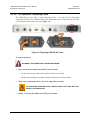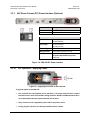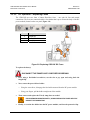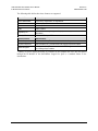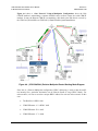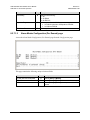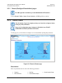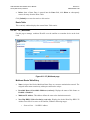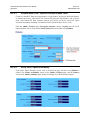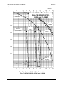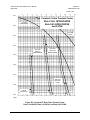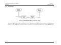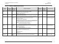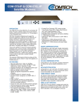
1
CDD-562L/564 Demodulator with IP Module Installation and Operation Manual (Includes data for the CDD-562L, CDD-564, and CDD-564L Configurations) For Firmware Version 1.6.10 or higher IMPORTANT NOTE: The information contained in this document supersedes all previously published information regarding these products. Product specifications are subject to change without prior notice. Part Number MN/CDD564L.IOM Revision 2 CDD-562L/564 Demodulator with IP Module Installation and Operation Manual (Includes data for the CDD-562L, CDD-564, and CDD-564L Configurations) For Firmware Version 1.6.10 or higher Part Number MN/CDD564L.IOM Revision 2 Copyright © 2012 Comtech EF Data. All rights reserved. Printed in the USA. Comtech EF Data, 2114 West 7th Street, Tempe, Arizona 85281 USA, 480.333.2200, FAX: 480.333.2161 This page is intentionally blank. ii TABLE OF CONTENTS TABLE OF CONTENTS .............................................................................................................. III TABLES ....................................................................................................................................... X FIGURES ..................................................................................................................................... X PREFACE ................................................................................................................................. XIII About this Manual ................................................................................................................................... xiii Reporting Comments or Suggestions Concerning this Manual ........................................................................... xiii Conventions and References ................................................................................................................... xiii Warnings, Cautions, and Notes............................................................................................................................... xiii Patents and Trademarks........................................................................................................................................... xiv Metric Conversion ................................................................................................................................................... xiv Recommended Standard Designations .................................................................................................................. xiv Safety and Compliance ............................................................................................................................ xiv Electrical Safety and Compliance........................................................................................................................... xiv Grounding................................................................................................................................................................. xiv Electrical Installation .................................................................................................................................................xv Operating Environment .............................................................................................................................................xv European Union Radio Equipment and Telecommunications Terminal Equipment (R&TTE) Directive (1999/5/EC) and EN 301 489-1 ................................................................................................................................xv European Union Electromagnetic Compatibility (EMC) Directive (2004/108/EC) ........................................xv European Union Low Voltage Directive (LVD) (2006/95/EC) ...................................................................... xvi European Union RoHS Directive (2002/95/EC) ............................................................................................. xvii European Union Telecommunications Terminal Equipment Directive (91/263/EEC) ................................ xvii CE Mark ........................................................................................................................................................... xvii Warranty Policy ..................................................................................................................................... xviii Limitations of Warranty ........................................................................................................................................ xviii Exclusive Remedies................................................................................................................................................. xix Getting Help .............................................................................................................................................. xx Contacting Comtech EF Data ...................................................................................................................................xx Returning a Product for Upgrade or Repair ........................................................................................................... xxi CHAPTER 1. INTRODUCTION ............................................................................................. 1–1 1.1 Overview ...................................................................................................................................... 1–1 1.2 Functional Description ............................................................................................................... 1–3 1.3 Features ........................................................................................................................................ 1–5 iii CDD-562L/564 Demodulator with IP Module Table of Contents Revision 2 MN/CDD564L.IOM 1.3.1 Physical Description ............................................................................................................................. 1–5 1.3.2 Major Assemblies ................................................................................................................................. 1–5 1.3.3 Interoperability/Compatibility.............................................................................................................. 1–5 1.3.4 Dimensional Envelopes ........................................................................................................................ 1–6 1.3.5 Physical Features................................................................................................................................... 1–8 1.3.5.1 Front Panel ........................................................................................................................................ 1–8 1.3.5.2 Rear Panel ......................................................................................................................................... 1–9 1.3.6 Data Interfaces..................................................................................................................................... 1–10 1.3.7 Updating Demodulator Firmware...................................................................................................... 1–10 1.3.8 Fully Accessible System Topology (FAST) ..................................................................................... 1–10 1.4 Summary of Specifications ....................................................................................................... 1–12 1.4.1 Demodulator........................................................................................................................................ 1–12 1.4.1.1 70/140 MHz (CDD-564 only) ....................................................................................................... 1–12 1.4.1.2 L-Band (CDD-562L, CDD-564L) ................................................................................................ 1–13 1.4.2 Low Noise Block Converter (LNB) Support (CDD-564L only) .................................................... 1–14 1.4.3 Environmental and Physical............................................................................................................... 1–14 1.4.4 Network Protocols .............................................................................................................................. 1–14 1.4.5 BER (Bit Error Rate) .......................................................................................................................... 1–15 CHAPTER 2. INSTALLATION AND STARTUP .................................................................... 2–1 2.1 Unpacking and Inspecting the Shipment .................................................................................. 2–1 2.2 Rack-mounting the CDD-56X .................................................................................................... 2–2 2.2.1 Installing the Optional Rear-Mounting Support Brackets Kit ........................................................... 2–4 2.3 Initial Configuration ................................................................................................................... 2–5 2.4 Connecting External Cables ....................................................................................................... 2–5 CHAPTER 3. REAR PANEL CONNECTOR PINOUTS ........................................................ 3–1 3.1 CDD-56X Rear Panel Overview ................................................................................................ 3–1 3.2 CDD-56X Cable Connections ..................................................................................................... 3–2 3.2.1 Rx IF Connections ................................................................................................................................ 3–3 3.2.1.1 CDD-562L and CDD-564L L-Band Chassis Rx Input ................................................................. 3–3 3.2.1.2 CDD-564 70/140 MHz Chassis Rx Input....................................................................................... 3–3 3.2.2 Terrestrial Data Connection – 10/100 Ethernet (RJ-45 Traffic/M&C Port) ..................................... 3–4 3.2.3 Utility Connections ............................................................................................................................... 3–5 3.2.3.1 Remote Control (DB-9M) ............................................................................................................... 3–5 3.2.3.2 Console (RJ-11 Async-Serial Port) ................................................................................................. 3–5 3.3 CDD-56X Ground and Power Connections .............................................................................. 3–6 3.3.1 Chassis Ground Interface ..................................................................................................................... 3–6 3.3.2 100V/240V Alternating Current (AC) Power Interface (Standard) .................................................. 3–7 3.3.2.1 AC Operation – Applying Power .................................................................................................... 3–7 3.3.2.2 AC Operation – Replacing Fuses .................................................................................................... 3–8 iv CDD-562L/564 Demodulator with IP Module Table of Contents Revision 2 MN/CDD564L.IOM 3.3.3 48V Direct Current (DC) Power Interface (Optional)........................................................................ 3–9 3.3.3.1 DC Operation – Applying Power .................................................................................................... 3–9 3.3.3.2 DC Operation – Replacing Fuses .................................................................................................. 3–10 CHAPTER 4. IP MODULE ETHERNET INTERFACE ........................................................... 4–1 4.1 Introduction ................................................................................................................................. 4–1 4.1.1 Standard Features .................................................................................................................................. 4–1 4.1.2 10/100 BaseT Ethernet Interface ......................................................................................................... 4–2 4.1.3 Powerful Network Management.......................................................................................................... 4–2 4.1.4 Remote Firmware Update via FTP...................................................................................................... 4–2 4.1.5 Configuration Backup and Restore via FTP ....................................................................................... 4–3 4.1.6 Event Logging to Capture All Demodulator Activity ........................................................................ 4–3 4.1.7 Detailed Statistics of IP Traffic ............................................................................................................ 4–3 4.1.8 IGMP Support for Multicast ................................................................................................................ 4–3 4.1.9 Static IP Routing for Unicast and Multicast........................................................................................ 4–3 4.2 Demodulator Features ................................................................................................................ 4–3 4.2.1 3xDES Encryption with Ability to Change Keys ............................................................................... 4–4 4.2.2 IP Header Compression........................................................................................................................ 4–4 4.2.3 Payload Compression ........................................................................................................................... 4–5 4.2.3.1 ADLC vs LZS Compression Comparison...................................................................................... 4–5 4.3 IP Module Specifications ............................................................................................................ 4–6 4.3.1 Supported RFCs and Protocols ............................................................................................................ 4–6 4.3.2 CDD562L/564/564L Compatibility .................................................................................................... 4–6 4.4 Typical IP Module Operational Setups ..................................................................................... 4–7 4.4.1 IP Module Working Modes ................................................................................................................. 4–7 4.4.1.1 Router Working Mode – Point-to-Point ......................................................................................... 4–9 4.4.1.2 Router Working Mode – Point-to-Multipoint .............................................................................. 4–11 CHAPTER 5. UPDATING FIRMWARE ................................................................................. 5–1 5.1 Updating Firmware via the Internet ......................................................................................... 5–1 5.2 About Firmware Files, Naming, Versions and Formats .......................................................... 5–3 5.3 Ethernet FTP Upload Procedure ............................................................................................... 5–4 5.3.1 Getting Started: Preparing for the Firmware Download .................................................................... 5–4 5.3.2 Downloading and Extracting the Firmware Update........................................................................... 5–6 5.3.3 Bulk Firmware FTP Upload Procedure .............................................................................................. 5–8 CHAPTER 6. ETHERNET-BASED REMOTE PRODUCT MANAGEMENT ......................... 6–1 6.1 Introduction ................................................................................................................................. 6–1 6.2 Ethernet Management Interface Protocols ............................................................................... 6–1 v CDD-562L/564 Demodulator with IP Module Table of Contents Revision 2 MN/CDD564L.IOM 6.3 SNMP Interface ........................................................................................................................... 6–1 6.3.1 Management Information Base (MIB) Files....................................................................................... 6–2 6.3.2 SNMP Community Strings .................................................................................................................. 6–2 6.3.3 SNMP Traps.......................................................................................................................................... 6–3 6.3.4 MIB-II.................................................................................................................................................... 6–4 6.3.5 Private MIB ........................................................................................................................................... 6–4 6.3.5.1 Administration Group ...................................................................................................................... 6–4 6.3.5.1.1 Access Lists Subgroup ................................................................................................ 6–4 6.3.5.1.2 Features Subgroup....................................................................................................... 6–4 6.3.5.1.3 3xDES Decryption Subgroup...................................................................................... 6–5 6.3.5.1.4 SMTP Subgroup.......................................................................................................... 6–5 6.3.5.1.5 SNMP Traps Subgroup ............................................................................................... 6–5 6.3.5.2 Interface Group ................................................................................................................................. 6–5 6.3.5.2.1 Ethernet Interface Subgroup ....................................................................................... 6–5 6.3.5.2.2 Demodulator Interface Subgroup ................................................................................ 6–5 6.3.5.3 Route Table Group ........................................................................................................................... 6–5 6.3.5.4 Protocols Group ................................................................................................................................ 6–5 6.3.5.4.1 IGMP Subgroup .......................................................................................................... 6–6 6.3.5.5 Maintenance Group .......................................................................................................................... 6–6 6.3.5.6 Statistics Group................................................................................................................................. 6–6 6.3.5.6.1 IP Routing Statistics Subgroup ................................................................................... 6–6 6.3.5.6.2 Ethernet Statistics Subgroup ....................................................................................... 6–6 6.3.5.6.3 Satellite Statistics Subgroup........................................................................................ 6–6 6.3.5.7 Demodulator Configuration Group ................................................................................................. 6–6 6.3.5.7.1 Rx Parameters ............................................................................................................. 6–6 6.3.5.7.2 Alarm Mask Parameters .............................................................................................. 6–7 6.3.5.7.3 Reference Parameters .................................................................................................. 6–7 6.3.5.7.4 LNB Parameters .......................................................................................................... 6–7 6.3.5.8 Monitor Group .................................................................................................................................. 6–7 6.3.5.8.1 Unit Monitor ............................................................................................................... 6–7 6.3.5.8.2 Rx Monitor .................................................................................................................. 6–7 6.3.5.8.3 LNB Monitor............................................................................................................... 6–7 6.3.5.8.4 Stored Events Log ....................................................................................................... 6–7 6.3.5.8.5 Stored Statistics ........................................................................................................... 6–7 6.3.5.9 Utilities Group .................................................................................................................................. 6–7 6.4 Telnet Interface ........................................................................................................................... 6–8 6.4.1 Telnet Operation via HyperTerminal .................................................................................................. 6–8 6.5 HTTP (Web Server) Interface ................................................................................................. 6–10 CHAPTER 7. QUICK START GUIDE .................................................................................... 7–1 7.1 Introduction ................................................................................................................................. 7–1 7.2 Getting Started ............................................................................................................................ 7–2 7.2.1 Equipment List ...................................................................................................................................... 7–2 7.2.2 Basic Equipment Setup ........................................................................................................................ 7–2 7.2.3 Transmit and Receive IF Configuration .............................................................................................. 7–3 vi CDD-562L/564 Demodulator with IP Module Table of Contents 7.2.4 7.2.5 Revision 2 MN/CDD564L.IOM Serial Console Port Command Line Interface (CLI) Configuration ................................................. 7–3 Restoring Factory Default Configuration............................................................................................ 7–5 7.3 Router Mode – Point-to-Point System Configuration ............................................................. 7–6 7.3.1 PC Configuration .................................................................................................................................. 7–6 7.3.2 Set CDM-IP Modems to Router Mode Operation ............................................................................. 7–7 7.3.3 Set CDD-56X Demodulator to Router Mode Operation ................................................................... 7–8 7.3.4 Set IP Address(es) ................................................................................................................................. 7–9 7.3.5 Set IP Stack DES Select Key to ClearRoute Table ............................................................................ 7–9 7.4 Troubleshooting the IP Module ............................................................................................... 7–11 7.4.1 Router Mode Troubleshooting ........................................................................................................... 7–12 CHAPTER 8. CDD-56X CLI AND TELNET OPERATION..................................................... 8–1 8.1 Overview ...................................................................................................................................... 8–1 8.1.1 Interface Access .................................................................................................................................... 8–2 8.2 CLI Menu Pages .......................................................................................................................... 8–3 8.2.1 Main Menu page ................................................................................................................................... 8–5 8.2.2 Administration page.............................................................................................................................. 8–6 8.2.2.1 Name/Password Configuration page .............................................................................................. 8–7 8.2.2.2 Access Lists page ............................................................................................................................. 8–8 8.2.2.3 Feature Configuration page ............................................................................................................. 8–9 8.2.2.4 Triple DES Decrypt Configuration (Per Demod) page ............................................................... 8–11 8.2.2.5 SMTP Configuration page............................................................................................................. 8–13 8.2.2.6 SNMP Configuration page ............................................................................................................ 8–14 8.2.2.7 Working Mode ............................................................................................................................... 8–15 8.2.2.8 Telnet Timeout ............................................................................................................................... 8–15 8.2.3 Interface Configuration page.............................................................................................................. 8–16 8.2.3.1 Ethernet Interface page................................................................................................................... 8–17 8.2.3.2 Satellite/HDLC Interface page ...................................................................................................... 8–18 8.2.3.2.1 Receive HDLC Addresses (Per Demod) page .......................................................... 8–19 8.2.4 Route Table Configuration page ........................................................................................................ 8–20 8.2.5 Protocol Configuration page .............................................................................................................. 8–22 8.2.5.1 IGMP Information page................................................................................................................. 8–23 8.2.5.2 ARP Table Utilities page ............................................................................................................... 8–24 8.2.5.3 (VLAN) Brouter page .................................................................................................................... 8–26 8.2.6 Vipersat Configuration page .............................................................................................................. 8–27 8.2.7 Satellite Demod Configuration page ................................................................................................. 8–28 8.2.7.1 Configuration page ......................................................................................................................... 8–29 8.2.7.1.1 Rx Configuration (Per Demod) page ........................................................................ 8–30 8.2.7.1.2 Alarm Masks Configuration (Per Demod) page ....................................................... 8–31 8.2.7.1.3 LNB Configuration (Per LNB) page ......................................................................... 8–32 8.2.7.2 Monitor page................................................................................................................................... 8–33 8.2.7.2.1 Rx Parameters page ................................................................................................... 8–34 8.2.7.2.2 Stored Events (Per Demod) page .............................................................................. 8–35 8.2.7.2.3 Link Statistics (Per Demod) page ............................................................................. 8–36 8.2.7.3 Information page ............................................................................................................................ 8–37 vii CDD-562L/564 Demodulator with IP Module Table of Contents Revision 2 MN/CDD564L.IOM 8.2.7.4 Features page .................................................................................................................................. 8–37 8.2.7.5 Utilities page ................................................................................................................................... 8–38 8.2.8 Operations and Maintenance page..................................................................................................... 8–39 8.2.8.1 Unit Information page .................................................................................................................... 8–41 8.2.8.2 Statistics Menu page....................................................................................................................... 8–42 8.2.8.2.1 IP Statistics page ....................................................................................................... 8–43 8.2.8.2.1.1 Filter/Drop Statistics page .................................................................................. 8–44 8.2.8.2.2 Ethernet Statistics page ............................................................................................. 8–47 8.2.8.2.3 WAN Statistics page ................................................................................................. 8–49 8.2.8.2.4 VLAN Statistics page................................................................................................ 8–50 8.2.8.2.5 Event Log page ......................................................................................................... 8–51 8.2.8.3 Database Operations page.............................................................................................................. 8–53 8.2.8.4 Diagnostics page............................................................................................................................. 8–54 CHAPTER 9. CDD-56X HTTP (WEB SERVER) INTERFACE ............................................. 9–1 9.1 Overview ...................................................................................................................................... 9–1 9.2 HTTP Interface Introduction .................................................................................................... 9–1 9.2.1 Interface Access .................................................................................................................................... 9–1 9.2.2 Interface Menu Tree and Splash Page ................................................................................................. 9–2 9.2.3 Selecting Demodulators ....................................................................................................................... 9–3 9.3 HTTP Interface Page Descriptions ............................................................................................ 9–4 9.3.1.2 Home | Contact ................................................................................................................................. 9–5 9.3.1.3 Home | Support ................................................................................................................................. 9–6 9.3.1.4 Home | Logoff................................................................................................................................... 9–7 9.3.2 Admin (Administrative) pages............................................................................................................. 9–8 9.3.2.1 Admin | Summary ............................................................................................................................ 9–8 9.3.2.2 Admin | Mode ................................................................................................................................... 9–9 9.3.2.3 Admin | Access ............................................................................................................................... 9–10 9.3.2.4 Admin | Features............................................................................................................................. 9–12 9.3.2.5 Admin | SNMP ............................................................................................................................... 9–13 9.3.2.6 Admin | Decryption ........................................................................................................................ 9–15 9.3.3 Demod (Configure Demodulator) pages........................................................................................... 9–16 9.3.3.1 Demod | Demod.............................................................................................................................. 9–16 9.3.3.2 Demod | Utilities ............................................................................................................................. 9–18 9.3.3.3 Demod | Status ................................................................................................................................ 9–19 9.3.3.4 Demod | Events............................................................................................................................... 9–20 9.3.3.5 Demod | Statistics ........................................................................................................................... 9–21 9.3.3.6 Demod | LNB.................................................................................................................................. 9–22 9.3.4 IP pages................................................................................................................................................ 9–23 9.3.4.1 IP | Ethernet..................................................................................................................................... 9–23 9.3.4.2 IP | HDLC ....................................................................................................................................... 9–25 9.3.4.3 IP | Routes ....................................................................................................................................... 9–27 9.3.4.4 IP | Multicast ................................................................................................................................... 9–28 9.3.4.5 IP | ARP........................................................................................................................................... 9–30 9.3.4.6 IP | VLAN ....................................................................................................................................... 9–31 9.3.4.7 IP | IGMP ........................................................................................................................................ 9–33 viii CDD-562L/564 Demodulator with IP Module Table of Contents Revision 2 MN/CDD564L.IOM 9.3.5 Stats Pages ........................................................................................................................................... 9–34 9.3.5.1 Stats | Ethernet ................................................................................................................................ 9–34 9.3.5.2 Stats | IP ........................................................................................................................................... 9–35 9.3.5.3 Stats | WAN .................................................................................................................................... 9–36 9.3.6 Maint (Maintenance) pages................................................................................................................ 9–37 9.3.6.1 Maint | Unit Info ............................................................................................................................. 9–37 9.3.6.2 Maint | Operations .......................................................................................................................... 9–38 9.3.6.3 Maint | Save .................................................................................................................................... 9–39 9.3.6.4 Maint | Reboot ................................................................................................................................ 9–40 APPENDIX A. FAST ACTIVATION PROCEDURE .............................................................. A–1 A.1 FAST System Overview ............................................................................................................. A–1 A.2 FAST Activation Procedure ...................................................................................................... A–2 A.2.1 FAST Activation via the Command Line Interface (CLI) ................................................................ A–2 A.2.2 FAST Activation via the HTTP (Web Server) Interface .................................................................. A–3 A.2.2.1 Record Serial Number..................................................................................................................... A–3 A.2.2.2 View Currently Installed Features.................................................................................................. A–4 A.2.2.3 Acquire/Enter FAST Option Purchase Access Code.................................................................... A–5 A.2.2.4 Verify FAST Option Availability .................................................................................................. A–5 APPENDIX B. FORWARD ERROR CORRECTION (FEC) .................................................. B–1 APPENDIX C. EB/N0 MEASUREMENT ................................................................................ C–1 APPENDIX D. CDM/CDD NMCS REMOTE PRODUCT MANAGEMENT PROTOCOL ...... D–1 D.1 Introduction ................................................................................................................................ D–1 D.2 Architecture ................................................................................................................................ D–2 D.3 NMCS Protocol .......................................................................................................................... D–3 D.3.1 Overview .............................................................................................................................................. D–3 D.3.2 Telnet Interface .................................................................................................................................... D–3 D.3.3 Basic Protocol ...................................................................................................................................... D–3 D.3.4 Command Structure ............................................................................................................................. D–4 D.3.4.1 Start of Packet .................................................................................................................................. D–5 D.3.4.2 Target Address................................................................................................................................. D–5 D.3.4.3 Address Delimiter............................................................................................................................ D–5 D.3.4.4 Instruction Code .............................................................................................................................. D–5 D.3.4.5 Instruction Code Qualifier .............................................................................................................. D–6 D.3.4.6 Optional Message Arguments ........................................................................................................ D–7 D.3.4.7 Table Support Qualifier .................................................................................................................. D–7 D.3.4.7.1 Index.......................................................................................................................... D–7 D.3.4.7.2 Argument Lists .......................................................................................................... D–8 D.3.4.8 End of Packet ................................................................................................................................... D–8 ix CDD-562L/564 Demodulator with IP Module Table of Contents Revision 2 MN/CDD564L.IOM D.4 Commands and Queries ............................................................................................................ D–9 D.4.1 IP Commands and Queries................................................................................................................ D–10 D.4.1.1 Admin Commands and Queries ................................................................................................... D–10 D.4.1.2 Interface Commands and Queries ................................................................................................ D–16 D.4.1.3 QoS Commands and Queries ....................................................................................................... D–17 D.4.1.4 Protocol Commands and Queries................................................................................................. D–20 D.4.1.5 Operations and Maintenance Commands and Queries............................................................... D–22 D.4.1.6 Redundancy Query........................................................................................................................ D–25 D.4.1.7 Routing Commands and Queries ................................................................................................. D–25 D.4.1.8 Statistics Commands and Queries ................................................................................................ D–27 D.4.1.8.1 Wan Stats ................................................................................................................ D–27 D.4.1.8.2 IP Stats .................................................................................................................... D–28 D.4.1.8.3 Ethernet Stats .......................................................................................................... D–30 D.4.1.8.4 QoS Stats ................................................................................................................. D–31 D.5 Param Files ............................................................................................................................... D–32 TABLES Table 3-1. Rear Panel External Cable Connections ................................................................................. 3–2 Table 6-1. MIB-II Support ........................................................................................................................ 6–4 Table B-1. Turbo Product Coding Processing Delay Comparison ......................................................... B–2 Table B-2. Turbo Product Coding Summary .......................................................................................... B–3 FIGURES Figure 1-1. CDD-562L L-Band Satellite Dual Demodulator.................................................................... 1–1 Figure 1-2. CDD-564/564L 70/140 MHz / L-Band Satellite Quad Demodulators ................................... 1–1 Figure 1-3. CDD-5xx Block Diagrams ..................................................................................................... 1–4 Figure 1-4. CDD-562L Dimensional Envelope ........................................................................................ 1–6 Figure 1-5. CDD-564/564L Dimensional Envelope ................................................................................. 1–7 Figure 1-6. Front Panel Views .................................................................................................................. 1–8 Figure 1-7. Rear Panel Views ................................................................................................................... 1–9 Figure 2-1. Unpacking and Inspecting the Shipment ................................................................................ 2–1 Figure 2-2. Installation into a Rack Enclosure .......................................................................................... 2–3 Figure 2-3. Optional Rear-Mounting Support Brackets Kit Installation................................................... 2–4 Figure 3-1. CDD-56X Rear Panel View ................................................................................................... 3–1 Figure 3-2. CDD-56X Typical Chassis Ground Interface ........................................................................ 3–6 Figure 3-3. CDD-56X AC Power Interface .............................................................................................. 3–7 Figure 3-4. Applying AC Power to the CDD-56X ................................................................................... 3–7 Figure 3-5. Replacing CDD-56X AC Fuses ............................................................................................. 3–8 Figure 3-6. CDD-56X DC Power Interface .............................................................................................. 3–9 Figure 3-7. Applying DC Power to the CDD-56X ................................................................................... 3–9 Figure 3-8. Replacing CDD-56X DC Fuses ........................................................................................... 3–10 Figure 4-1. (CDD-562L) Router Mode Point-to-Point Diagram ............................................................. 4–9 Figure 4-2. (CDD-564/564L) Point-to-Point Router Working Mode Diagram ..................................... 4–10 x CDD-562L/564 Demodulator with IP Module Table of Contents Revision 2 MN/CDD564L.IOM Figure 4-3. (CDD-562L) Point-to-MultiPoint Router Working Mode Diagram ................................... 4–11 Figure 4-4. (CDD-564/564L) Point-to-MultiPoint Router Working Mode Diagram ............................ 4–12 Figure 5-1. CDD-56X Rear Panel Connections to User PC ..................................................................... 5–2 Figure 7-1. CLI Main Menu via Telnet or HyperTerminal (CDD-56X shown) ....................................... 7–4 Figure 7-2. Router Mode Point-to-Point System Configuration ............................................................... 7–6 Figure 9-1. HTTP Interface “Splash” page ............................................................................................... 9–3 Figure 9-2. CDD-56X Home page ............................................................................................................ 9–4 Figure 9-3. Home | Contact page .............................................................................................................. 9–5 Figure 9-4. Home | Customer Support page.............................................................................................. 9–6 Figure 9-5. Home | Logoff page................................................................................................................ 9–7 Figure 9-6. Admin | Summary page .......................................................................................................... 9–8 Figure 9-7. Admin | Mode page ................................................................................................................ 9–9 Figure 9-8. Admin | Access page ............................................................................................................ 9–10 Figure 9-9. Admin | Features page .......................................................................................................... 9–12 Figure 9-10. Admin | SNMP page .......................................................................................................... 9–13 Figure 9-11. Admin | Decryption page ................................................................................................... 9–15 Figure 9-12. Demod | Demod page ......................................................................................................... 9–16 Figure 9-13. Demod | Utilities page ........................................................................................................ 9–18 Figure 9-14. Demod | Status page ........................................................................................................... 9–19 Figure 9-15. Demod | Events page .......................................................................................................... 9–20 Figure 9-16. Demod | Statistics page ...................................................................................................... 9–21 Figure 9-17. Demod | LNB page ............................................................................................................. 9–22 Figure 9-18. IP | Ethernet page ............................................................................................................... 9–23 Figure 9-19. IP | HDLC page .................................................................................................................. 9–25 Figure 9-20. IP | Routes page .................................................................................................................. 9–27 Figure 9-21. IP | Multicast page .............................................................................................................. 9–28 Figure 9-22. IP | ARP page ..................................................................................................................... 9–30 Figure 9-23. IP | VLAN page .................................................................................................................. 9–31 Figure 9-24. IP | IGMP page ................................................................................................................... 9–33 Figure 9-25. Stats | Ethernet page ........................................................................................................... 9–34 Figure 9-26. Stats | IP page ..................................................................................................................... 9–35 Figure 9-27. Stats | WAN page ............................................................................................................... 9–36 Figure 9-28. Maint | Unit Info page ........................................................................................................ 9–37 Figure 9-29. Maint | Operations page ..................................................................................................... 9–38 Figure 9-30. Maint | Save page ............................................................................................................... 9–39 Figure 9-31. Maint | Reboot page ........................................................................................................... 9–41 Figure B-1. Comtech EF Data Turbo Product Codec Rate 3/4 QPSK (OQPSK), 8-PSK, and 16-QAM ...... ......................................................................................................................................................... B–4 Figure B-2. Comtech EF Data Turbo Product Codec Rate 7/8 QPSK(OQPSK) , 8-PSK, and 16-QAM ...... ......................................................................................................................................................... B–5 Figure B-3. Comtech EF Data Turbo Product Codec Rate 21/44 QPSK, Rate 0.95 QPSK, and Rate 0.95 8-PSK ............................................................................................................................................... B–6 Figure D-1. CDM/CDD NMCS Basic Architecture Layout .................................................................... D–2 xi CDD-562L/564 Demodulator with IP Module Table of Contents Revision 2 MN/CDD564L.IOM This page is intentionally blank. xii PREFACE About this Manual This manual provides installation and operation information for the Comtech EF Data CDD-562L (L-Band) Dual, CDD-564 (70/140 MHz) Quad, and CDD-564L (L-Band) Quad Demodulator with IP Module. The demodulators include support for externally connected Low-Noise Block Downconverters (LNBs). This is document is intended for the persons responsible for the operation and maintenance of the demodulator. Reporting Comments or Suggestions Concerning this Manual Comments and suggestions regarding the content and design of this manual are appreciated. To submit comments, contact the Comtech EF Data Technical Publications Department: [email protected] Conventions and References Warnings, Cautions, and Notes A WARNING gives information about a possible hazard that MAY CAUSE DEATH or SERIOUS INJURY. A CAUTION gives information about a possible hazard that MAY CAUSE INJURY or PROPERTY DAMAGE. A NOTE gives important information about a task or the equipment. A REFERENCE directs the user to additional information about a task or the equipment. xiii CDD-562L/564 Demodulator with Optional IP Module Preface Revision 2 MN/CDD564L.IOM Patents and Trademarks See all of Comtech EF Data's Patents and Patents Pending at http://patents.comtechefdata.com. Comtech EF Data acknowledges that all trademarks are the property of the trademark owners. Metric Conversion Metric conversion information is located on the inside back cover of this manual. This information is provided to assist the operator in cross-referencing non-metric to metric conversions. Recommended Standard Designations Recommended Standard (RS) Designations have been superseded by the new designation of the Electronic Industries Association (EIA). References to the old designations are shown only when depicting actual text displayed on the screen of the unit (RS-232, RS-485, etc.). All other references in the manual will be shown with the EIA designations. The user should carefully review the following information. Safety and Compliance Electrical Safety and Compliance The unit complies with the EN 60950 Safety of Information Technology Equipment (Including Electrical Business Machines) safety standard. IF THE UNIT IS OPERATED IN A VEHICLE OR MOVABLE INSTALLATION, MAKE SURE THE UNIT IS STABLE. OTHERWISE, EN 60950 SAFETY IS NOT GUARANTEED. Grounding PROPER GROUNDING PROTECTION IS REQUIRED: The installation instructions require that the integrity of the protective earth must be ensured and that the equipment shall be connected to the protective earth connection at all times. The CDD-562L/564 is designed for connection to a power system that has separate ground, line and neutral conductors. The equipment is not designed for connection to a power system that has no direct connection to ground. It is therefore imperative during installation, configuration, and operation for the user to ensure that the unit has been properly grounded using the ground stud provided on the rear panel of the unit. xiv CDD-562L/564 Demodulator with Optional IP Module Preface Revision 2 MN/CDD564L.IOM Electrical Installation The equipment is rated for operation over the range 100 - 240 volts AC. It has a maximum power consumption of 140 Watts (when all inputs are supplying DC to LNBs), and draws a maximum of 1.5 Amps. The installation and connection to the line supply must be made in compliance to local or national wiring codes and regulations. The CDD-562L/564 is shipped with a line inlet cable suitable for use in the country of operation. If it is necessary to replace this cable, ensure the replacement has an equivalent specification. Examples of acceptable ratings for the cable include HAR, BASEC and HOXXX-X. Examples of acceptable connector ratings include VDE, NF-USE, UL, CSA, OVE, CEBEC, NEMKO, DEMKO, BS1636A, BSI, SETI, IMQ, KEMA-KEUR and SEV. Operating Environment DO NOT OPERATE THE UNIT IN ANY OF THESE EXTREME OPERATING CONDITIONS: • AMBIENT TEMPERATURES LESS THAN 0°C (32°F) OR MORE THAN 50°C (122°F). (MAXIMUM STORAGE TEMPERATURE ALLOWED IS -25°C (-13°F) TO 85°C (185°F)). • PRECIPITATION, CONDENSATION, OR HUMID ATMOSPHERES OF MORE THAN 95% RELATIVE HUMIDITY. • UNPRESSURIZED ALTITUDES OF MORE THAN 2000 METRES (6561.7 FEET). • EXCESSIVE DUST. • FLAMMABLE GASES. • CORROSIVE OR EXPLOSIVE ATMOSPHERES. European Union Radio Equipment and Telecommunications Terminal Equipment (R&TTE) Directive (1999/5/EC) and EN 301 489-1 Independent testing verifies that the unit complies with the European Union R&TTE Directive, its reference to EN 301 489-1 (Electromagnetic compatibility and Radio spectrum Matters [ERM]; ElectroMagnetic Compatibility [EMC] standard for radio equipment and services, Part 1: Common technical requirements), and the Declarations of Conformity for the applicable directives, standards, and practices that follow: European Union (2004/108/EC) • Electromagnetic Compatibility (EMC) Directive EN 55022 Class B – Limits and Methods of Measurement of Radio Interference Characteristics of Information Technology Equipment. xv CDD-562L/564 Demodulator with Optional IP Module Preface Revision 2 MN/CDD564L.IOM • EN 55024 – Information Technology Equipment: Immunity Characteristics, Limits, and Methods of Measurement. • EN 61000-3-2 – Harmonic Currents Emission • EN 61000-3-3 – Voltage Fluctuations and Flicker. • EN 61000-4-2 – ESD Immunity • EN 61000-4-4 – EFT Burst Immunity • EN 61000-4-5 – Surge Immunity • EN 61000-4-6 – RF Conducted Immunity • EN 61000-4-8 – Power Frequency Magnetic Field Immunity • EN 61000-4-9 – Pulse Magnetic Field Immunity • EN 61000-4-11 – Voltage Dips, Interruptions, and Variations Immunity • EN 61000-4-13 – Immunity to Harmonics • Federal Communications Commission Federal Code of Regulation FCC Part 15, Subpart B. TO ENSURE THAT THE UNIT COMPLIES WITH THESE STANDARDS, OBEY THESE INSTRUCTIONS: • Use coaxial cable that is of good quality (e.g., RG58/U (50Ω) or RG59/U (75Ω)) for connections to the IF Tx and Rx (transmit and receive) BNC female connectors. • Use Type 'D' connectors that have back-shells with continuous metallic shielding. Type ‘D’ cabling must have a continuous outer shield (either foil or braid, or both). The shield must be bonded to the back-shell. • Operate the unit with its cover on at all times. European Union Low Voltage Directive (LVD) (2006/95/EC) Symbol Description <HAR> Type of power cord required for use in the European Community. ! CAUTION: Double-pole/Neutral Fusing ACHTUNG: Zweipolige bzw. Neutralleiter-Sicherung xvi CDD-562L/564 Demodulator with Optional IP Module Preface Revision 2 MN/CDD564L.IOM International Symbols Symbol Definition Symbol Definition Alternating Current Protective Earth Fuse Chassis Ground For additional symbols, refer to Warnings, Cautions and Notes listed earlier in this Preface. European Union RoHS Directive (2002/95/EC) This unit satisfies (with exemptions) the requirements specified in the European Union Directive on the Restriction of Hazardous Substances in Electrical and Electronic Equipment (EU RoHS, Directive 2002/95/EC). European Union Telecommunications Terminal Equipment Directive (91/263/EEC) In accordance with the European Union Telecommunications Terminal Equipment Directive 91/263/EEC, the unit should not be directly connected to the Public Telecommunications Network. CE Mark Comtech EF Data declares that the unit meets the necessary requirements for the CE Mark. xvii CDD-562L/564 Demodulator with Optional IP Module Preface Revision 2 MN/CDD564L.IOM Warranty Policy Comtech EF Data products are warranted against defects in material and workmanship for a specific period from the date of shipment, and this period varies by product. In most cases, the warranty period is two years. During the warranty period, Comtech EF Data will, at its option, repair or replace products that prove to be defective. Repairs are warranted for the remainder of the original warranty or a 90 day extended warranty, whichever is longer. Contact Comtech EF Data for the warranty period specific to the product purchased. For equipment under warranty, the owner is responsible for freight to Comtech EF Data and all related customs, taxes, tariffs, insurance, etc. Comtech EF Data is responsible for the freight charges only for return of the equipment from the factory to the owner. Comtech EF Data will return the equipment by the same method (i.e., Air, Express, Surface) as the equipment was sent to Comtech EF Data. All equipment returned for warranty repair must have a valid RMA number issued prior to return and be marked clearly on the return packaging. Comtech EF Data strongly recommends all equipment be returned in its original packaging. Comtech EF Data Corporation’s obligations under this warranty are limited to repair or replacement of failed parts, and the return shipment to the buyer of the repaired or replaced parts. Limitations of Warranty The warranty does not apply to any part of a product that has been installed, altered, repaired, or misused in any way that, in the opinion of Comtech EF Data Corporation, would affect the reliability or detracts from the performance of any part of the product, or is damaged as the result of use in a way or with equipment that had not been previously approved by Comtech EF Data Corporation. The warranty does not apply to any product or parts thereof where the serial number or the serial number of any of its parts has been altered, defaced, or removed. The warranty does not cover damage or loss incurred in transportation of the product. The warranty does not cover replacement or repair necessitated by loss or damage from any cause beyond the control of Comtech EF Data Corporation, such as lightning or other natural and weather related events or wartime environments. The warranty does not cover any labor involved in the removal and or reinstallation of warranted equipment or parts on site, or any labor required to diagnose the necessity for repair or replacement. xviii CDD-562L/564 Demodulator with Optional IP Module Preface Revision 2 MN/CDD564L.IOM The warranty excludes any responsibility by Comtech EF Data Corporation for incidental or consequential damages arising from the use of the equipment or products, or for any inability to use them either separate from or in combination with any other equipment or products. A fixed charge established for each product will be imposed for all equipment returned for warranty repair where Comtech EF Data Corporation cannot identify the cause of the reported failure. Exclusive Remedies Comtech EF Data Corporation’s warranty, as stated is in lieu of all other warranties, expressed, implied, or statutory, including those of merchantability and fitness for a particular purpose. The buyer shall pass on to any purchaser, lessee, or other user of Comtech EF Data Corporation’s products, the aforementioned warranty, and shall indemnify and hold harmless Comtech EF Data Corporation from any claims or liability of such purchaser, lessee, or user based upon allegations that the buyer, its agents, or employees have made additional warranties or representations as to product preference or use. The remedies provided herein are the buyer’s sole and exclusive remedies. Comtech EF Data shall not be liable for any direct, indirect, special, incidental, or consequential damages, whether based on contract, tort, or any other legal theory. xix CDD-562L/564 Demodulator with Optional IP Module Preface Revision 2 MN/CDD564L.IOM Getting Help Review the Warranty Policy before contacting Comtech EF Data Technical Support or Customer Service. Contacting Comtech EF Data Contact Comtech EF Data for: • Technical Support – Product support or training. • Customer Service – Information on returning an in-warranty or out-of-warranty product for upgrade or repair. Be prepared to provide the product model number and its serial number. Contact Comtech EF Data Customer & Technical Support during normal business hours (Monday through Friday, 8 A.M. to 5 P.M Mountain Standard Time (MST)): For: CDM-625 Technical Support and Service Comtech EF Data Web Site Contact: Telephone +1.480.333.4357 Email [email protected] Fax +1.480.333.2500 Main Page http://www.comtechefdata.com Customer and Technical Support RMA (Return Material Authorization) http://www.comtechefdata.com/support.asp http://www.comtechefdata.com/rmaform.asp Comtech EF Data Main Number +1.480.333.2200 Mailing Address 2114 West 7th Street Tempe, Arizona 85281 USA xx CDD-562L/564 Demodulator with Optional IP Module Preface Revision 2 MN/CDD564L.IOM Returning a Product for Upgrade or Repair Step Task 1 Go to the Comtech EF Data Service page (http://www.comtechefdata.com/ service.asp) and read the Return Material Authorization section in its entirety. 2 Request a Return Material Authorization Number: • On the Comtech EF Data Service page: Select the Return Material Authorization hyperlink. • On the Comtech EF Data Support page (http://www.comtechefdata.com/support.asp): Click [Send RMA Request] (http://www.comtechefdata.com/rmaform.asp); • Fill out the RMA form completely; • Click [Send Email]. • Alternately: o Send an e-mail providing this same detailed information to Comtech EF Data Customer Service ([email protected]). o Contact Comtech EF Data Customer & Technical Support by phone or fax. 3 Pack the product in its original shipping carton and protective packaging. 4 Ship the product back to Comtech EF Data. Shipping charges should be prepaid. xxi CDD-562L/564 Demodulator with Optional IP Module Preface Revision 2 MN/CDD564L.IOM Notes: xxii Chapter 1. INTRODUCTION 1.1 Overview The CDD-562L (Figure 1-1) is a dual (2-channel) L-Band satellite demodulator. The CDD-564L (Figure 1-2) is a quad (4-channel) L-Band satellite demodulator; the CDD-564 is the 70/140 MHz IF version of the same demodulator; apart from the IF frequency band, these two demodulators are essentially identical. Equipped with IP router, these demodulators are intended for closed network applications. Figure 1-1. CDD-562L L-Band Satellite Dual Demodulator Figure 1-2. CDD-564/564L 70/140 MHz / L-Band Satellite Quad Demodulators To simplify reading, the product is referred to hereafter as either “the demodulator” or “the CDD56X”. If there is a need to distinguish between the units, the specific model number will be identified. 1–1 CDD-562L/564 Demodulator with IP Module Introduction Revision 2 MN/CDD564L.IOM The CDD-56X provides many standard and optional features: • Fast acquisition demodulator: o CDD-562L: Two independent demodulators o CDD-564/564L: Four independent demodulators • CDD-564: Demodulator programmed from 50–90, 100–180 MHz IF range (70./140 MHz) • CDD-562L/CDD-564L: Demodulators programmed from 950–1950 MHz (L-Band) • Optional: Variable data rates from 16 kbps to 9.98 Mbps • Optional: Rates above 512 kbps • 2nd Generation Turbo Product Coding (TPC) Forward Error Correction (FEC) • QPSK modulation • Optional: 8-PSK and 16-QAM • SNMP, HTTP (Web Server), and Telnet Remote Product Management • LNB Support: 10 MHz reference and LNB power 1–2 CDD-562L/564 Demodulator with IP Module Introduction 1.2 Revision 2 MN/CDD564L.IOM Functional Description The CDD-562L has two Rx channels. The CDD-564/564L have four Rx channels. The demodulators have two fundamentally different types of interface: Ethernet and IF. The Ethernet interface is a bidirectional path, which connects with the customer’s equipment through an Ethernet Switch. The Ethernet interface is a 10/100 BaseT Ethernet port where data flow is the combined output of the demodulator channels. Control and status information also uses this port. The IF interfaces provides independent unidirectional links (Rx only) with the satellite via the downlink equipment. In the demodulator, the Rx IF signal in the range (50–90 or 100–180 MHz for 70/140 MH z units, and 950–1950 MHz for L-Band units) is translated to an intermediate frequency (approx. 465 MHz for L-Band), and then further translated to baseband using the carrier recovery VCO. This is a complex mix, resulting in the signal once more being split into an in-phase (I) and a quadrature (Q) component. An AGC circuit maintains the desired signal level constant over a broad range. Following this, the I and Q signals are sampled by high-speed (flash) A/D converters. All processing beyond this conversion is purely digital, performing the functions of Nyquist filtering, carrier recovery, and symbol timing recovery. The resultant demodulated signal is fed, in soft decision form, to the selected FEC decoder (Turbo). After decoding, the recovered clock and data pass to the IP Module where traffic is examined and processed for four channels before it is delivered to the Ethernet port. The demodulator signal processing functions are performed in two, large Field-Programmable Gate Array (FPGA), which permits rapid implementation of changes, additions and enhancements in the field. These signal-processing functions are controlled and monitored by a 32-bit RISC microprocessor, which also controls all front panel indicators, serial and Ethernet interfaces. As shown in the block diagrams depicted in Figure 1-3, the demodulator is physically comprised of a single printed circuit board assembly, with integral Turbo FEC and IP router. 1–3 CDD-562L/564 Demodulator with IP Module Introduction Revision 2 MN/CDD564L.IOM CDD-562L Block Diagram CDD-564/564L Block Diagram Figure 1-3. CDD-5xx Block Diagrams 1–4 CDD-562L/564 Demodulator with IP Module Introduction 1.3 1.3.1 Revision 2 MN/CDD564L.IOM Features Physical Description The demodulators are constructed as a 1RU-high, rack-mounting chassis, which can be freestanding if desired. Rack handles at the front facilitate removal from and placement into a rack. 1.3.2 Major Assemblies Model Assembly Description PL/10915-1 AC Chassis PL/10915-2 DC Chassis PL/11548-1 AC Chassis PL/11548-2 DC Chassis CDD-562L PL/10735-2 Demodulator Card CDD-564L PL/10735-1 Demodulator Card CDD-562L/564L CDD-564 1.3.3 Interoperability/Compatibility The demodulator is interoperable with the Comtech EF Data CDM-570 and CDM-570L Satellite Modems populated with the optional IP Module/router, as well as other Comtech EF Data IPenabled products (including modems and Performance Enhancement Proxies). The demodulator supports the functions associated with receive side of the equipment. 1–5 CDD-562L/564 Demodulator with IP Module Introduction 1.3.4 Revision 2 MN/CDD564L.IOM Dimensional Envelopes Figure 1-4. CDD-562L Dimensional Envelope 1–6 CDD-562L/564 Demodulator with IP Module Introduction Revision 2 MN/CDD564L.IOM Figure 1-5. CDD-564/564L Dimensional Envelope 1–7 CDD-562L/564 Demodulator with IP Module Introduction 1.3.5 Revision 2 MN/CDD564L.IOM Physical Features 1.3.5.1 Front Panel CDD-562L CDD-564/564L Figure 1-6. Front Panel Views Figure 1-6 shows the front panel of the demodulators. Depending on the unit, the front panel features six (CDD-562L) or eight (CDD-564/564L) Light-Emitting-Diode (LED) indicators. The LEDs indicate, in a summary fashion, the status of the unit: • Overall Unit Status • Stored Event • Ethernet Link Activity • 10BaseT or 100BaseT Ethernet Activity • Traffic Status for each of the two (CDD-562L) or four (CDD-564/564L) Rx Traffic (receive) channels 1–8 CDD-562L/564 Demodulator with IP Module Introduction 1.3.5.2 Revision 2 MN/CDD564L.IOM Rear Panel Chapter 3. REAR PANEL CONNECTORS AND PINOUTS CDD-562L CDD-564 CDD-564L Figure 1-7. Rear Panel Views Figure 1-7 shows the rear panels of the demodulators. External cables are attached to connectors on the rear panel of the unit, comprised as follows: Connector Type Connector Group (Chapter 3 Sect. Ref.) IF (Sect. 3.2) Terrestrial Data (Sect. 3.3) Utility (Sect. 3.4) Power/Ground (Sect 3.5) Name CDD-562L (L-Band) CDD-564 (70/140 MHz) CDD-564L (L-Band) Rx 1 (Rx A on CDD-564L) Type ’N’ female BNC female Type ’N’ female Rx 2 (Rx B on CDD-564L) Type ’N’ female BNC female Type ’N’ female Rx 3 (Rx C on CDD-564L) N/A BNC female Type ’N’ female Rx 4 (Rx D on CDD-564L) N/A BNC female Type ’N’ female Function IF Input 10/100 Ethernet RJ-45 female Ethernet Traffic Console RJ-11 female Async Serial Console Port Remote Control 9-pin Type ‘D’ male Remote Interface (EIA-232) for Factory Test AC See Sect. 3.5.1 DC (Optional) See Sect. 3.5.2 Ground #10-32 stud Chassis power Common Chassis Ground The European EMC Directive (EN55022, EN50082-1) requires using properly shielded cables for DATA I/O. These cables must be double-shielded from endto-end, ensuring a continuous ground shield. 1–9 CDD-562L/564 Demodulator with IP Module Introduction 1.3.6 Revision 2 MN/CDD564L.IOM Data Interfaces The demodulators include, as standard, a 10/100 BaseT Ethernet port that serves as both a terrestrial data (i.e., IP traffic) interface and a management and control interface (i.e., the HTTP Web Server Interface). 1.3.7 Updating Demodulator Firmware Chapter 5. UPDATING FIRMWARE The demodulators store theirs firmware internally in flash memory, which simplifies the firmware updating process. If a firmware update is needed, it can be acquired by download from Comtech EF Data’s Web site or from Comtech EF Data Customer Support during normal business hours via e-mail or on CD by standard mail delivery. The firmware update, once acquired, can be transferred from an external user PC that is connected to the unit 10/100BaseT Ethernet port. Once connectivity has been established with the demodulator, the upgrade can be performed by "FTPing" the download from the PC. 1.3.8 Fully Accessible System Topology (FAST) Appendix A. FAST ACTIVATION PROCEDURE The demodulators incorporate a large number of optional features. In order to permit a lower initial cost, a demodulator may be purchased with only the desired features enabled. If, at a later date, the user wishes to upgrade the functionality of a unit, Comtech EF Data provides Fully Accessible System Topology (FAST), a technology which permits the purchase and installation of options through special authorization codes. These unique Fast Access Codes may be purchased from Comtech EF Data during normal business hours, and then loaded into the unit using either the serial/Telnet CLI (connected to the rear panel “Remote control” port) or the unit’s Web Server (HTTP) Interface. FAST System Theory FAST allows an operator to order a unit precisely tailored for the initial application. When service requirements change, FAST allows the operator to upgrade the topology of the unit onlocation, within minutes, and without having to remove the unit from the setup. This accelerated upgrade is possible due to FAST’s extensive use of the programmable logic devices incorporated into Comtech EF Data products. FAST Implementation Hardware options can be ordered and installed either at the factory or in the field. In the field, the operator can select options that can be easily activated, depending on the current hardware 1–10 CDD-562L/564 Demodulator with IP Module Introduction Revision 2 MN/CDD564L.IOM configuration of the unit. The unique, register-specific FAST Access Code that is purchased from Comtech EF Data enables configuration of the available hardware. FAST Accessible Options Hardware options for basic demodulators can be ordered and installed either at the factory or in the field. The operator can select options that can be activated easily in the field, depending on the current hardware configuration of the demodulator. A unique access code enables configuration of the available hardware. As standard features, the demodulator is configured with an Integrated IP router compatible with the optional IP Module/router available in the CDM-570/570L Satellite Modem, and Integrated 2nd Generation Turbo FEC compatible with the CDM-570/570L. The following table shows the available FAST and FAST-accessible hardware options: Option Description and Comments Low-Rate Variable QPSK TPC Codec IP Router -48 VDC Mid-Rate Variable Full-Rate Variable High-Rate Variable 3xDES Data Encryption Data rate 16 kbps to 512 kbps Modulation Type Turbo Product Codec (IESS-315 compliant) 10/100 Base-T Interface -48 VDC Prime Power Supply Data rate 16 kbps to 2.048 Mbps Data rate 16 kbps to 5.0 Mbps Data rate 16 kbps to 9.98 Mbps Uses NIST certified 3x core Software Version 1.5.1 and later Uses proprietary IP Header Compressions Software Version 1.5.1 and later Uses proprietary Payload Compressions Software Version 1.5.1 and later 8-PSK Modulation 16-QAM Modulation IP Header Compression Payload Compression 8-PSK 16-QAM 1–11 Installation Method Base Unit Standard Standard Standard Hardware FAST FAST FAST FAST FAST FAST FAST FAST CDD-562L/564 Demodulator with IP Module Introduction 1.4 Revision 2 MN/CDD564L.IOM Summary of Specifications 1.4.1 Demodulator 1.4.1.1 70/140 MHz (CDD-564 only) System Specification Frequency Range 50 to 90 or 100 to 180 MHz, 100 Hz resolution Symbol Rate Range 16 ksps to 3.0 Msps Data Rate Range Each demodulator independently in 1 bps increments Rate 3/4 QPSK TPC 16 kbps to 4.5 Mbps Rate 7/8 QPSK TPC 16 kbps to 5.25 Mbps Rate 0.95 QPSK TPC 16 kbps to 5.666Mbps Rate 3/4 8-PSK TPC 16 kbps to 6.75 Mbps Rate 7/8 8-PSK TPC 16 kbps to 8.5 Mbps Rate 0.95 8-PSK TPC 16 kbps to 7.875 Mbps Rate 3/4 16-QAM TPC 16 kbps to 9.0 Mbps Rate 7/8 16-QAM TPC 16 kbps to 9.98 Mbps Descrambling Comtech to IESS-315 Rate 3/4, 0.95 QPSK Rate 3/4, 0.95 8-PSK FEC Turbo Product Rate 3/4, 16-QAM Rate 7/8, QPSK, 8-PSK, 16-QAM Inputs (4X) Type ‘BNC’ female Input Impedance 50 or 75Ω user selection Return Loss 17 dB min Traffic and Management Interface 10/100 BaseT Ethernet RJ-45 Command Line Interface (CLI) EIA-232, RJ-11 Factory Test Connector DB-9 male Frequency Reference Internal ± 0.06 ppm, 32 to 122°F (0 to 50°C) External None Demodulator Input Power Range -30 to –60 dBm Max Composite Level +35 dBc, up to –5 dBm Acquisition Range ± 1 to ± 32 kHz (1 kHz steps) < 625 ksps Monitor Functions Eb/No Frequency Offset, BER LNB current and voltage Rx signal level 1–12 CDD-562L/564 Demodulator with IP Module Introduction 1.4.1.2 Revision 2 MN/CDD564L.IOM L-Band (CDD-562L, CDD-564L) System Specification Frequency Range 950 to 1950 MHz Symbol Rate Range 16 ksps to 3.0 Msps Data Rate Range Each demodulator independently in 1 bps increments Rate 3/4 QPSK TPC 16 kbps to 4.5 Mbps Rate 7/8 QPSK TPC 16 kbps to 5.25 Mbps Rate 0.95 QPSK TPC 16 kbps to 5.666Mbps Rate 3/4 8-PSK TPC 16 kbps to 6.75 Mbps Rate 7/8 8-PSK TPC 16 kbps to 7.875 Mbps Rate 0.95 8-PSK TPC 16 kbps to 8.5 Mbps Rate 3/4 16-QAM TPC 16 kbps to 9.0 Mbps Rate 7/8 16-QAM TPC 16 kbps to 9.98 Mbps Descrambling Comtech to IESS-315 Rate 3/4, 0.95 QPSK Rate 3/4, 0.95 8-PSK FEC Turbo Product Rate 3/4, 16-QAM Rate 7/8, QPSK, 8-PSK, 16-QAM Inputs CDD-562L: (2X) Type ‘N’ female CDD-564L: (4X) Type ‘N’ female Input Impedance 50Ω, 17 dB minimum return loss Traffic and Management Interface 10/100 BaseT Ethernet RJ-45 Command Line Interface (CLI) EIA-232, RJ-11 Factory Test Connector DB-9 male Frequency Reference Internal ± 0.06 ppm, 32 to 122°F (0 to 50°C) External None Demodulator Input Power Range -130 + 10 log (Symbol Rate) to –90 +10 Log (Symbol Rate) Max Composite Level +40 dBc, up to –5 dBm Acquisition Range ± 1 to ± 32 kHz (1 kHz steps) < 625 ksps ± 1 to ± 200 kHz ≥ 625 ksps Monitor Functions Eb/No Frequency Offset, BER LNB current and voltage Rx signal level 1–13 CDD-562L/564 Demodulator with IP Module Introduction 1.4.2 1.4.3 Low Noise Block Converter (LNB) Support (CDD-564L only) Parameters Specifications LNB Voltage +13 volts, +18 volts, and +24 volts DC or OFF at 500 mA max per Rx input 10 MHz Reference -3 dBm ± 3 dB via Rx center conductor Power Level Selectable ON or OFF per Rx input Environmental and Physical Parameters Temperature 1.4.4 Revision 2 MN/CDD564L.IOM Specifications Operating 32 to 122°F (0 to 50°C) Storage -13 to 185°F (-25 to 85°C) Power Supply 100 to 240 volts AC, 50/60 Hz Optional: 48 VDC input (38 to 60) Power Consumption 75 W typical (140 W max – powering 4 LNBs) Fuse 120/230 VAC: T3, 15A, slow-blow 20 mm 48VDC (38 to 60 VDC): T8.0A, slow-blow 20 mm Physical Dimensions 1RU high x 19 inches wide x 16 inches deep ( 43.8 mm h x 482.6 mm w x 406 mm d) Weight 7 lbs (3.2 kg) Agency Approvals CE Mark FCC Part 15, Class B Network Protocols Protocols RFC 768 - UDP RFC 2045 - MIME RFC 791-IP RFC 2236 – IGMP v2 RFC 792 – ICMP RFC 2474 – DS Field RFC 793 – TCP RFC 2475 - ADS RFC 826 - ARP RFC 2578 - SMI RFC 856 - Telnet RFC 2597 – PHB Group RFC 862 – Ping RFC 2598 - PHB RFC 894 – IP RFC 2616 - HTTP RFC 959 – FTP RFC 2821 - SMTP RFC 1112 – IP Multicast RFC 3412 - SNMP RFC 1213 –SNMP MIB II RFC 3416 – SNMPv2 RFC 1812 – IPv4 Routers RFC 3418 – SNMP MIB 1–14 CDD-562L/564 Demodulator with IP Module Introduction 1.4.5 Revision 2 MN/CDD564L.IOM BER (Bit Error Rate) IMPORTANT NOTE: Starting with Release 1.4.1 of the CDM-570/570L firmware, the maximum symbol rate has been increased from 2.5 to 3.0 Symbol/sec. This has been done without modification to the hardware and as a consequence there may be a small degradation in BER versus Eb/No performance for rates above 2.5 Msymbols/sec. The degradation is as follows: Rates from 2.5 to 2.65 Msps: degradation < 0.1 dB Rates from 2.65 to 2.80 Msps: degradation < 0.2 dB Rates from 2.80 to 3.00 Msps: degradation < 0.3 dB TURBO PRODUCT CODEC Rate 3/4 QPSK Rate 3/4 8-PSK Rate 3/4 16-QAM Rate 3/4 (8-PSK) Guaranteed Eb/No: (typical value in parentheses) Rate 3/4 (16-QAM) Guaranteed Eb/No: (typical value in parentheses) BER=10-6 3.8dB (3.4dB) 6.2dB (5.8dB) 7.4dB (7.0dB) BER=10-7 4.1dB (3.7dB) 6.4dB (6.0dB) 7.8dB (7.3dB) BER=10-8 4.4dB (4.0dB) 6.8dB (6.3dB) 8.2dB (7.7dB) Rate 7/8 (Q) Guaranteed Eb/No: (typical value in parentheses) Rate 7/8 (8-PSK) Guaranteed Eb/No: (typical value in parentheses) Rate 7/8 (16-QAM) Guaranteed Eb/No: (typical value in parentheses) BER=10-6 4.3dB (4.0 dB) 7.0dB (6.6dB) 8.1dB (7.7dB) BER=10-7 4.4dB (4.1 dB) 7.1dB (6.7dB) 8.2dB (7.8dB) BER=10-8 4.5dB (4.2 dB) 7.2dB (6.8dB) 8.3dB (7.9dB) Rate 0.95 (Q) Guaranteed Eb/No: (typical value in parentheses) Rate 0.95 (8-PSK) Guaranteed Eb/No: (typical value in parentheses) BER=10-6 6.4dB (6.0dB) 9.3dB (8.9dB) BER=10-7 6.7dB (6.3dB) 9.8dB (9.4dB) BER=10-8 6.9dB (6.5dB) 10.3dB (9.9dB) For: (With two adjacent carriers, each 7 dB higher than the desired carrier) TURBO PRODUCT CODEC Rate 7/8 QPSK Rate 7/8 8-PSK Rate 7/8 16-QAM Rate 3/4 (Q) Guaranteed Eb/No: (typical value in parentheses) For: BER (With two adjacent carriers, each 7 dB higher than the desired carrier) TURBO PRODUCT CODEC Rate 0.95 QPSK Rate 0.95 (8-PSK) For: (With two adjacent carriers, each 7 dB higher than the desired carrier) Monitor Functions Eb/No estimate: 2 to 16 dB (± 0.25 dB accuracy) Corrected Bit Error Rate: 1E-3 to 1E-9 Frequency offset: ± 200 kHz range 100 Hz resolution) Buffer fill state (in percent) Receive signal level: -20 to -90 dBm (± 5.0 dB accuracy) 1–15 CDD-562L/564 Demodulator with IP Module Introduction Revision 2 MN/CDD564L.IOM Notes: 1–16 Chapter 2. INSTALLATION and STARTUP 2.1 Unpacking and Inspecting the Shipment Figure 2-1. Unpacking and Inspecting the Shipment The CDD-56X Satellite Demodulator with IP Module, its Installation and Operation Manual, and its power cord were packaged and shipped in a reusable cardboard carton containing protective foam spacing. This equipment contains parts and assemblies sensitive to damage by Electrostatic Discharge (ESD). Use ESD precautionary procedures when handling the equipment. 2–1 CDD-562L/564 Demodulator with IP Module Installation and Startup Revision 2 MN/CDD564L.IOM Once opened, inspect the shipment: Step 2.2 Task 1 Keep all shipping materials for storage or reshipment. 2 Check the packing list to ensure the shipment is complete. 3 Inspect the equipment for any possible damage incurred during shipment. Contact the carrier and Comtech EF Data immediately to submit a damage report if damage is evident. 4 Review the Installation and Operation Manual carefully to become familiar with operation. 5 Proceed to Section 2.2 Rack-mounting the CDD-56X. Rack-mounting the CDD-56X When mounting the CDD-56X into a rack enclosure: • PROPER GROUNDING PROTECTION IS REQUIRED. The equipment must be connected to the protective earth connection at all times. It is therefore imperative that the unit is properly grounded, using the ground stud provided on the unit rear panel, during installation, configuration, and operation. • PROPER AIR VENTILATION IS REQUIRED. In a rack system where there is high heat discharge, provide forced-air cooling with top- or bottom-mounted fans or blowers. o Make sure there is adequate clearance inside the enclosure, especially at the side for air ventilation. o Air temperature inside the rack enclosure should never exceed 50°C (122°F). For information about custom rack enclosures, contact Comtech EF Data Customer Support during normal business hours or visit Comtech EF Data’s Web site (www.comtechefdata.com/support.asp). The CDD-56X CANNOT have rack slides mounted to the sides of the chassis. Cooling fans and exhaust vents are provided here – air flow must not be impeded. Comtech EF Data recommends that an alternate method of support is provided within the rack, such as standard rack shelves (Figure 2-2) or the optional RearMounting Support Brackets Kit (Figure 2-3). If there is any doubt, contact Comtech EF Data Customer Support during normal business hours. 2–2 CDD-562L/564 Demodulator with IP Module Installation and Startup Revision 2 MN/CDD564L.IOM Figure 2-2. Installation into a Rack Enclosure Mount the CDD-56X in its assigned position in the rack enclosure. Use, as required: • A standard rack-mounted shelf; • User-supplied screws to secure the front panel to the rack enclosure threaded front mounting rails; • Comtech EF Data’s optional KT/6228-2 (4”) or KT/6228-3 (10”) Rear-Mounting Support Brackets Kit. 2–3 CDD-562L/564 Demodulator with IP Module Installation and Startup Revision 2 MN/CDD564L.IOM 2.2.1 Installing the Optional Rear-Mounting Support Brackets Kit Detail Description 1 Back of Unit 2 Rack Enclosure Threaded Rear Mounting Rail (typical) Item Kit / Quantity Part Number Description 2 HW/10-32SHLDR Shoulder Screw, #10 4 4 HW/10-32FLT Flat Washer, #10 3 2 2 HW/10-32SPLIT Lock Washer, #10 4 2 2 HW/10-32HEXNUT Hex Nut, #10 5 4 4 HW/10-32x1/2RK Bolt, #10, Rear Support Bracket 2 – FP/6138-2 Bracket, Rear Support – 4” – 2 FP/6138-3 Bracket, Rear Support – 10” KT/6228-2 KT/6228-3 1 2 2 6 Figure 2-3. Optional Rear-Mounting Support Brackets Kit Installation 2–4 CDD-562L/564 Demodulator with IP Module Installation and Startup Revision 2 MN/CDD564L.IOM The tools needed to install the KT/6228-2 (4”) or KT/6228-3 (10”) Rear-Mounting Support Brackets Kit are as follows: • A medium Phillips™ screwdriver • A 5/32-inch SAE Allen™ Wrench • An adjustable Crescent™ wrench. To install the kit (Figure 2-3): Step 2.3 Task 1 Use the #10 flat washers, #10 split washers, and #10 hex nuts to secure the #10 shoulder screws to the unit chassis through the rear right and left side mounting slots. 2 Use the #10 rack bracket bolts to install the rear support brackets onto the rack enclosure threaded rear mounting rails. 3 Mount the unit into the rack enclosure. Ensure that the shoulders of the #10 shoulder screws properly engage into the rear support bracket slots. Initial Configuration There are no internal jumpers to configure, no interface cards to install, and no other options to install—all configurations are carried out entirely via firmware. The unit will ship with a default 64 kbps, QPSK, Rate 3/4 configuration; the unit should first be further configured locally, using the EIA-232 Console Interface. Note: The auto-sensing AC power supply does not require any adjustments. Simply plug in the supplied line cord, and turn on the switch on the rear panel. 2.4 Connecting External Cables Once the desired configuration settings have been made, proceed to connect all external cables to the connectors outlined in the next chapter (Chapter 3. REAR PANEL CONNECTORS AND PINOUTS). Should difficulties occur, call Comtech EF Data Customer Support for assistance. 2–5 CDD-562L/564 Demodulator with IP Module Installation and Startup Revision 2 MN/CDD564L.IOM Notes: 2–6 Chapter 3. REAR PANEL CONNECTOR PINOUTS 3.1 CDD-56X Rear Panel Overview (Top) CDD-562L Dual Demodulator with IP Module (L-Band) (Center) CDD-564 Quad Demodulator with IP Module (70/140 MHz) (Bottom) CDD-564L Quad Demodulator with IP Modulator (L-Band) Figure 3-1. CDD-56X Rear Panel View The CDD-56X Satellite Demodulator rear panel connectors, shown here in Figure 3-1, provide all necessary external connections between the modem and other equipment: • Section 3.2 summarizes the cabling connections provided on the rear panel interface, grouped according to service function. • Section 3.3 summarizes the grounding and power features for the unit. 3–1 CDD-562L/564 Demodulator with IP Module Rear Panel Connections 3.2 Revision 2 MN/CDD564L.IOM CDD-56X Cable Connections Table 3-1. Rear Panel External Cable Connections Sect. 3.2.1 3.2.2 3.2.3 Service Type Rx IF Terrestrial Data Connector Type Connector Name CDD-562L (L-Band) CDD-564 (70/140 MHz) CDD-564L (L-Band) Rx 1 (Rx A on CDD-564L) Type ’N’ female BNC female Type ’N’ female Rx 2 (Rx B on CDD-564L) Type ’N’ female BNC female Type ’N’ female Rx 3 (Rx C on CDD-564L) N/A BNC female Type ’N’ female Rx 4 (Rx D on CDD-564L) N/A BNC female Type ’N’ female Connector Function RF Input RJ-45 female Ethernet Traffic and M&C Remote Control 9-pin Type ‘D’ male NOT FOR CUSTOMER USE Remote Interface for Factory Test Console RJ-11 female Async Serial Console Port 10/100 Ethernet Utility The European EMC Directive (EN55022, EN50082-1) requires using properly shielded cables for DATA I/O. These cables must be double-shielded from end-to-end, ensuring a continuous ground shield. 3–2 CDD-562L/564 Demodulator with IP Module Rear Panel Connections 3.2.1 Revision 2 MN/CDD564L.IOM Rx IF Connections 3.2.1.1 CDD-562L and CDD-564L L-Band Chassis Rx Input There may be DC voltages present on the Type ‘N’ Rx IF connectors, up to a maximum of 48 volts. The Rx IF input port connectors on the L-Band demodulators are 50Ω ‘N’ female types. Two connectors, labeled Rx1 and Rx2, are provided on the CDD-562L (shown at left), while four connectors labeled Rx A through Rx D are available on the CDD-564L (shown to the right). The return loss on these ports is typically better than 17 dB, and if the user wishes to connect to a 75Ω system, an inexpensive ‘N’ to ‘F’ type adapter can be used and is available as an optional accessory. While there will be a reduction in return loss when doing this, the effect in most systems will be imperceptible. 3.2.1.2 CDD-564 70/140 MHz Chassis Rx Input The Rx IF Input port connectors are BNC female types, with a programmable impedance of 50Ω or 75Ω. Four connectors, labeled Rx 1 through Rx 4, are provided on the CDD-564. 3–3 CDD-562L/564 Demodulator with IP Module Rear Panel Connections 3.2.2 Revision 2 MN/CDD564L.IOM Terrestrial Data Connection – 10/100 Ethernet (RJ-45 Traffic/M&C Port) The 10/100 BaseT Ethernet port is a standard 8-pin RJ-45 modular jack, It is used for Ethernet traffic, management of CDD-562L/564/564L IP Module functions via Telnet/HTTP/SNMP, and for updating of the demodulator’s IP Module firmware. Note the following: Pin # Function 1 Tx+ 2 Tx- 3 Rx+ 4 N/C 5 N/C 6 Rx- 7 N/C 8 N/C 3–4 CDD-562L/564 Demodulator with IP Module Rear Panel Connections 3.2.3 Revision 2 MN/CDD564L.IOM Utility Connections 3.2.3.1 Remote Control (DB-9M) THIS CONNECTOR IS NOT A STANDARD EIA-232 INTERFACE. IT IS NOT INTENDED FOR CUSTOMER USE. IT IS INTENDED FOR FACTORY TEST USE ONLY. CONTACT CEFD CUSTOMER SUPPORT PRIOR TO CONNECTING ANY EQUIPMENT TO THIS INTERFACE. The Remote Control interface is a 9-pin Type ‘D’ male (DB-9M) connector, reserved for use in in-factory test applications. Note the following: Pin # 1 6 2 7 3 8 4 9 5 3.2.3.2 Description Direction Ground -- Selected Demod RS-422 Rx Data + In EIA-232 Transmit Data (38.4k, 8N1 fixed) Out Selected Demod RS-422 Rx Data - In EIA-232 Receive Data (38.4k, 8N1 fixed) In Selected Demod RS-422 Tx Clock + Out Selected Demod I-Channel monitor Out Selected Demod RS-422 Tx Clock - Out Selected Demod Q-Channel monitor Out Console (RJ-11 Async-Serial Port) The Console port is a standard 6-pin RJ-11 modular jack. The Async-Serial EIA-232 DCE Console services the IP Module Command Line Interface (CLI). The supplied adapter cable connects the user PC to the Console port. A user-supplied terminal emulator program such as HyperTerminal or Tera Term is used for management of demodulator and IP Module functions. Note the following: Pin # Function 1 Ground 2 Rx 3 Tx 4 Ground 5 Not used 6 Not used 3–5 CDD-562L/564 Demodulator with IP Module Rear Panel Connections 3.3 Revision 2 MN/CDD564L.IOM CDD-56X Ground and Power Connections 3.3.1 Chassis Ground Interface PROPER GROUNDING PROTECTION IS REQUIRED. The equipment must be connected to the protective earth connection at all times. It is therefore imperative that the unit is properly grounded, using the ground stud provided on the unit rear panel, during installation, configuration, and operation. (Top) Standard AC Unit (Bottom) Optional 48V DC Unit Figure 3-2. CDD-56X Typical Chassis Ground Interface Use the #10-32 stud, located adjacent to the power interface, for connecting a common chassis ground among equipment. The AC power interface provides the safety ground. 3–6 CDD-562L/564 Demodulator with IP Module Rear Panel Connections 3.3.2 Revision 2 MN/CDD564L.IOM 100V/240V Alternating Current (AC) Power Interface (Standard) Feature Description 1 On / Off Switch 2 Press-fit Fuse Holder 3 IEC Three-prong Connector AC Power Specifications Input Power 40W maximum, 20W typical Input Voltage 100V to 240V AC, +6%/-10%, autosensing (total absolute max. range is 90V to 254V AC) Connector Type IEC Fuse Protection Line and neutral fusing (2X) 5mm x 20mm Slow-blow type fuses: T3.15A (100V or 240V AC operation) Figure 3-3. CDD-56X AC Power Interface 3.3.2.1 AC Operation – Applying Power Figure 3-4. Applying AC Power to the CDD-56X To apply AC power to the CDD-56X (Figure 3-4): • First, plug the provided AC power cord female end into the unit. • Then, plug the AC power cord male end into the user-supplied power source. • Finally, switch the unit ON. 3–7 CDD-562L/564 Demodulator with IP Module Rear Panel Connections 3.3.2.2 Revision 2 MN/CDD564L.IOM AC Operation – Replacing Fuses The CDD-56X uses two 5mm x 20mm Slow-blow fuses – one each for line and neutral connections. The fuses are contained within a fuse holder that is press-fit into the body of the IEC power module (located on the rear panel, Figure 3-5). Figure 3-5. Replacing CDD-56X AC Fuses To replace the fuse(s): DISCONNECT THE POWER SUPPLY BEFORE PROCEEDING! • • First, unseat the fuse holder from the IEC power module. o Use the slot to pry the holder outward from the IEC power module. o Pull the holder straight out, and then swing the holder away from the module. Then, remove and replace the T3.15A (3.15 Amp) fuses as needed. • FOR CONTINUED OPERATOR SAFETY, ALWAYS REPLACE THE FUSES WITH THE CORRECT TYPE AND RATING. Finally, re-seat the fuse holder in the IEC power module. 3–8 CDD-562L/564 Demodulator with IP Module Rear Panel Connections 3.3.3 Revision 2 MN/CDD564L.IOM 48V Direct Current (DC) Power Interface (Optional) Feature Description 1 On / Off Switch 2 Plug-in Power Receptacle DC Power Specifications Input Power 48 watts (typical) 55 watts (maximum) Input Voltage 48 volts DC nominal (36 volts to 60 volts) Connector Type Corcom PS series Mating Connector Corcom GA210 or Molex 03-12-1026 Fuse Protection Line and Neutral Fusing (2X) 5mm x 20mm Slow-blow type fuses: T8A (8 Amp) Figure 3-6. CDD-56X DC Power Interface 3.3.3.1 DC Operation – Applying Power Figure 3-7. Applying DC Power to the CDD-56X To apply DC power to the CDD‐56X: • First, assemble the user‐supplied red (+) and black (–) DC power leads and their crimped terminals into the shell of the module mating connector. Number 18 AWG minimum wires are recommended. Note the keyed orientation for the wires. • Then, connect the user‐supplied DC power leads to the power source. • Finally, plug the connector into the keyed module socket as shown. 3–9 CDD-562L/564 Demodulator with IP Module Rear Panel Connections 3.3.3.2 Revision 2 MN/CDD564L.IOM DC Operation – Replacing Fuses The CDD-56X uses two 5mm x 20mm Slow-blow fuses – one each for line and neutral connections. The fuses are contained within a fuse holder that is press-fit into the body of the DC power module (located on the rear panel, Figure 3-8). Feature Description 1 Hinged Flap 2 Press-fit Fuse Holder 3 Fuse (2X) Figure 3-8. Replacing CDD-56X DC Fuses To replace the fuse(s): DISCONNECT THE POWER SUPPLY BEFORE PROCEEDING! • First, using a flat-bladed screwdriver, use the slot to pry open and swing back the hinged flap. • Next, extract the press-fit fuse holder: • o Using the screwdriver, disengage the fuse holder outward from the DC power module. o Using your fingers, pull the holder straight out of the module. Then, remove and replace the T8A (8 Amp) fuses as needed. • FOR CONTINUED OPERATOR SAFETY, ALWAYS REPLACE THE FUSES WITH THE CORRECT TYPE AND RATING. Finally, re-seat the fuse holder into the DC power module, and close the protective flap. 3–10 Chapter 4. IP MODULE ETHERNET INTERFACE 4.1 Introduction For information specific to CDD-56X IP Module operation when deployed in a Vipersat system, please consult adjunct Comtech EF Data publication MN/22137 – Vipersat CDD-56X Series Satellite Network Demodulator Router User Guide. The CDD-562X Satellite Demodulator’s integral IP Module Ethernet Interface is intended for closed network Single Channel Per Carrier (SCPC) links. It concentrates traffic from two or four independent demodulators into a single Ethernet port, making it ideal for networked VSAT applications. The CDD-56X can also be utilized in a Vipersat satellite bandwidth management system. 4.1.1 Standard Features • 10/100BaseT Ethernet Interface (RJ-45) • Powerful network management: o SNMP with public and private MIB o Telnet interface for remote product M & C o Web Server interface for complete product management o Console Port interface for local network management • Remote software/firmware upgrade via FTP • Configuration backup and restore via FTP • Event Logging to capture all IP Module activity • Detailed Statistics of IP traffic 4–1 CDD-562L/564 Demodulator with IP Module IP Module Ethernet Interface 4.1.2 Revision 2 MN/CDD564L.IOM • IGMP support for Multicast • Static IP routing for unicast and multicast • Symmetric and/or asymmetric operation for maximum bandwidth efficiency • Point-to-Point or Point-to-Multipoint configuration • Interoperable with the CDM-570/570L with IP Module, CDM-IP550, and CDM-IP 300L 10/100 BaseT Ethernet Interface In Router Mode operation, the 10/100BaseT Ethernet Interface is used for routing IP traffic received over the satellite to another device on the local LAN, and for monitor and control purposes. 4.1.3 Powerful Network Management Local or remote management of all demodulator and IP Module functions is available via SNMP, Telnet, or HTTP. The demodulator may be configured, operated and monitored using any of the following methods: User Interface Local or remote – Ethernet via 10/100 BaseT Traffic interface Local or remote – Ethernet via 10/100 BaseT Traffic interface SNMP Telnet 4.1.4 Connection Demod Functions IP MODULE Functions Manual Reference ALL ALL Chapter 6 ALL ALL Chapter 6 Serial Command Line Interface (CLI) Local – Serial RS-232 via Console Port ALL ALL Chapter 8 Web Server Local or remote – Ethernet via 10/100 BaseT Traffic interface ALL ALL Chapter 9 Remote Firmware Update via FTP Chapter 5. UPDATING FIRMWARE The CDD-56X Satellite Demodulator with IP Module uses flash memory technology internally. Firmware update archive files may be downloaded from the Internet to a user PC (from Comtech EF Data’s website), or obtained through Comtech EF Data Customer Support via e-mail or on CD by standard mail delivery. Once acquired from Comtech EF Data, new firmware can be uploaded from the user PC by File Transfer Protocol (FTP) without opening the unit or having to be in the same physical location. 4–2 CDD-562L/564 Demodulator with IP Module IP Module Ethernet Interface 4.1.5 Revision 2 MN/CDD564L.IOM Configuration Backup and Restore via FTP All demodulator configuration parameters are stored in a simple text file. The parameter file can easily be retrieved locally or remotely by FTP. The file can then be used to quickly configure a replacement unit if needed. 4.1.6 Event Logging to Capture All Demodulator Activity All activity can be stored into an easy-to-read Event Log. This file also can be retrieved locally or remotely by FTP. 4.1.7 Detailed Statistics of IP Traffic IP traffic statistics are continuously updated and allow detailed performance analysis or can be used to identify traffic problems. The statistics are available through the Serial Console locally, or can be gathered remotely by SNMP, Telnet, or HTTP. 4.1.8 IGMP Support for Multicast IGMP is a standard feature in the demodulator. If enabled as an IGMP client, it responds to IGMP queries for the configured multicast routes. If enabled as an IGMP server, it generates IGMP queries and transmits multicast traffic per IGMP clients’ request. If there are no active IGMP clients on the LAN, it will stop forwarding the multicast traffic (received from the satellite) to the LAN. 4.1.9 Static IP Routing for Unicast and Multicast Up to 256 static routes can be entered into the demodulator to direct IP traffic to another device on the local LAN. 4.2 Demodulator Features Appendix A. FAST ACTIVATION PROCEDURE Additional features can be added quickly on site to the CDD-56X by entering FAST Access Codes purchased from Comtech EF Data. FAST-accessible options include: • 3xDES Data Encryption • IP Header Compression • Payload Compression 4–3 CDD-562L/564 Demodulator with IP Module IP Module Ethernet Interface 4.2.1 Revision 2 MN/CDD564L.IOM 3xDES Encryption with Ability to Change Keys The demodulator optionally supports 3xDES-128 (using NIST certified 3x core) decryption for the highest-level security. For link encryption, each unit supports eight decryption keys. 4.2.2 IP Header Compression Header Compression also is an optional feature of the demodulator. The demodulator supports Header Compression for the following Ethernet and Layer 3 & 4 Headers: Supported Ethernet Headers Ethernet 2.0 Ethernet 2.0 + VLAN-tag Ethernet 2.0 + MPLS 802.3-raw 802.3-raw + VLAN-tag 802.3 + 802.2 802.3 + 802.2 + VLAN-tag 802.3 + 802.2 + SNAP 802.3 + 802.2 + SNAP + VLAN-tag 802.3 + 802.2 + SNAP + MPLS Supported Layer 3&4 Headers IP TCP UDP RTP (Codec Independent) Header Compression reduces the required VoIP bandwidth by 60 percent. Example: A G.729a voice codec, operating at 8 kbps, will occupy 32 kbps once encapsulated into IP framing on a LAN. Using IP/UDP/RTP Header Compression, the same traffic only needs 10.8 kbps total WAN satellite bandwidth to cross the link. A total maximum of 64 simultaneous VoIP calls can be compressed. Normal Web/HTTP traffic can be reduced an additional 10% via IP/TCP header compression. Header Compression Configuration – Header Compression is completely independent from QoS, and there is no configuration required except enabling the Header Compression feature on both the sending and receiving Comtech EF Data IP modem/demod. Packets with a Header Compression supported header will automatically be identified for compression. The only configuration consideration is the Header Compression Refresh Rate. This is how many compressed header packets will be sent before a single full header packet is sent. Sometimes compressed header traffic could be lost during deteriorated satellite link conditions. Sending a full header packet will allow the return of the traffic stream. The Refresh Rate can be increased for poor satellite link conditions or decreased to further reduce overhead. 4–4 CDD-562L/564 Demodulator with IP Module IP Module Ethernet Interface 4.2.3 Revision 2 MN/CDD564L.IOM Payload Compression Traffic optimization through Payload Compression is another optional feature of the demodulator. 4.2.3.1 • FAST feature to upgrade • Uses AHA© chip • Compression algorithm applied to all data (HDLC header excluded). • Compression statistics are fed back to QoS in order to maximize WAN utilization while maintaining priority, jitter and latency. • 1024 simultaneous compression sessions to maximize compression across multiple distinct traffic flows. • Compression algorithm not applied to RTP streams because this traffic is already compressed and would only INCREASE the satellite bandwidth if compressed again. • Additional statistics have been added to the compression statistics menu in order to provide feedback on the compression efficiency that has been achieved. • Payload Compression is selectable on a per route basis. ADLC vs LZS Compression Comparison These numbers have been generated using an internally created test program. This program takes the target benchmark files and splits the files into payload size chunks and compresses each chunk in a separate invocation of the compression algorithm. This is important to note because most compression algorithms are applied to the entire file data set as a single invocation of the compression algorithm, which is easier for other types of compression algorithms (LZS, GZIP in specific). This, of course, does not apply to streamed packet data across an IP network (e.g., FTP transfer). Algorithm Payload size File Set Ratio Algorithm Payload size File Set Ratio ADLC 1472 Calgary 1.76 LZS 1472 Calgary 1.66 ADLC 1000 Calgary 1.76 LZS 1000 Calgary 1.66 ADLC 500 Calgary 1.77 LZS 500 Calgary 1.68 ADLC 100 Calgary 2.09 LZS 100 Calgary 1.97 ADLC 1472 Canterbury 1.71 LZS 1472 Canterbury 1.61 ADLC 1000 Canterbury 1.72 LZS 1000 Canterbury 1.62 ADLC 500 Canterbury 1.74 LZS 500 Canterbury 1.63 ADLC 100 Canterbury 2.04 LZS 100 Canterbury 1.91 4–5 CDD-562L/564 Demodulator with IP Module IP Module Ethernet Interface 4.3 4.3.1 Revision 2 MN/CDD564L.IOM IP Module Specifications Supported RFCs and Protocols RFC RFC 768 User Datagram Protocol RFC 792 Internet Control Message Protocol RFC 826 An Ethernet Address Resolution Protocol RFC 862 Echo Protocol RFC 959 File Transfer Protocol RFC 1213 Management Information Base for Network Management of TCP/IP-based internet: MIB-II RFC 2045 Multipurpose Internet Mail Extensions (MIME) RFC 2474 Definition of the Differentiated Services Field (DS Field) in the Ipv4 and Ipv6 Headers RFC 2578 Structure of Management Information Version 2 (SMIv2) RFC 2598 An Expedited Forwarding PHB RFC 2821 Simple Mail Transfer Protocol RFC 3416 Version 2 of the Protocol Operations for the Simple Network Management Protocol (SNMP) 4.3.2 Protocol RFC 791 Internet Protocol RFC 793 Transmission Control Protocol RFC 856 Telnet Binary Transmission RFC 894 A Standard for the Transmission of IP Datagrams over Ethernet Networks RFC 1112 Host Extensions for IP Multicasting RFC 1812 Requirements for IP Version 4 Routers RFC 2236 Internet Group Management Protocol, Version 2 RFC 2475 An Architecture for Differentiated Services RFC 2597 Assured Forwarding PHB Group RFC 2616 Hypertext Transfer Protocol – HTTP/1.1 RFC 3412 Message Processing and Dispatching for the Simple Network Management Protocol (SNMP) RFC 3418 Management Information Base (MIB) for the Simple Network Management Protocol (SNMP) CDD562L/564/564L Compatibility The CDD-56X is compatible with other Comtech EF Data IP modems (referred to hereafter as CDM-IP), provided the modems have similar operating modes and IP options. The following is a list of compatible CDM-IP modems: CDD-564L IP FW Version Version 1.1.0 or later Version 1.1.0 or later Version 1.1.0 or later Comtech EF Data IP Modem / IP FW Version CDM-IP 550 Version 1.3.0 or later CDM-IP 300L Version 1.3.0 or later CDM-570/570L Version 1.4.0 or later 4–6 Comments Must have Framer II Module (PL/9956-1) to support Data Compression IP option Must have Framer II Module (PL/9956-1) to support Data Compression IP option CDD-562L/564 Demodulator with IP Module IP Module Ethernet Interface 4.4 Revision 2 MN/CDD564L.IOM Typical IP Module Operational Setups The CDD-56X has several modes of operation. The typical setup examples that follow serve as a means to determine the best mode of operation for the appropriate network topology and Ethernet traffic environment. 4.4.1 IP Module Working Modes Typical CDM-IP modems support two Working Modes: Managed Switch Mode (formerly easyConnect™) and Router Mode; however, the demodulator only supports Router Mode, so the CDM-IP modem that is transmitting to demodulator must be in Router Mode. Non-IP traffic is not supported in Router Mode. Router Mode supports three HDLC Addressing Modes: Point-to-Point, Small Network, and Large Network. Separate HDLC Modes allow the user to minimize the HDLC overhead transmitted over the satellite based on the size of their network. In Router/Point-to-Point Mode, no HDLC address is transmitted, Router/Small Network transmits 1 byte, and Router/Large Network transmits 2 bytes as part of HDLC header for each packet. In the sections that follow, the functionality of these modes is described in further detail, in order to optimize the Comtech EF Data IP modems in the network, based upon Network Topology and Ethernet Traffic requirements. 1. The demodulator only supports Router Mode, so the CDM-IP modem that is transmitting to demodulator must be in Router Mode. 2. The HDLC Address Mode of the Comtech EF Data IP modems must be identical to pass traffic between the TX modems and the demodulator. 3. Changing the HDLC Address Mode of the demodulator requires the IP Module to be rebooted. Before the user can select a different mode, the demodulator will notify the user that changing the mode will require a reboot. Working Mode HDLC Address Mode Network Topology Ethernet Traffic Router Mode Point-to-Point Point-to-Point only Both sites on different LAN subnet IP v4 only Router Mode Small Network Point-to-Point or Point-to-Multipoint (up to 254 sites) All sites on different LAN subnet IP v4 only Router Mode Large Network Point-to-Point or Point-to-Multipoint (up to 32766 sites) All sites on different LAN subnet IP v4 only Feature Support - The demodulator also has several standard and optional features to further optimize security, performance and efficiency. 4–7 CDD-562L/564 Demodulator with IP Module IP Module Ethernet Interface Revision 2 MN/CDD564L.IOM The following table defines how these features are supported: Standard Features Additional Notes HDLC Address Mode Point-to-Point, Small Network, or Large Network Access Lists 4 Clients by IP or IP Subnet Multicast RX all or specific Multicast streams IGMP IGMPv1, IGMPv2 Upgrade by FTP By local LAN or remotely through satellite (requires a two way connection to demodulator) * Quality of Service Min/Max, Max/Priority, or DiffServ Optional Features Additional Notes Header Compression Must be enabled if any TX modem stream has Header Compression enabled. Payload Compression Must be enabled if any TX modem stream has Payload Compression enabled. 3xDES Encryption Must be enabled if any TX modem stream has 3xDES Encryption enabled. Up to 8 Decrypt Keys or random * Quality of Service (QoS) processing is performed by the transmit end of the link and passed through the IP Module in the demodulator. Support for QoS is a standard feature in the demodulator. 4–8 CDD-562L/564 Demodulator with IP Module IP Module Ethernet Interface 4.4.1.1 Revision 2 MN/CDD564L.IOM Router Working Mode – Point-to-Point Figure 4-1 shows an example setup using the CDD-562L L-Band Satellite Dual Demodulator at a Hub site to receive two separate DVB return channels. Note the following: • The CDD-562L and all CDM-IP modems are in Point-to-Point Mode. • Each remote site has a CDM-IP modem with a default static route. • The CDD-562L has a default static route directing traffic to the hub router. • The hub router would have routes defined for each remote network that would be directed to the DVB Encapsulator. Figure 4-1. (CDD-562L) Router Mode Point-to-Point Diagram 4–9 CDD-562L/564 Demodulator with IP Module IP Module Ethernet Interface Revision 2 MN/CDD564L.IOM Figure 4-2 shows an example setup using the CDD-564 (70/140 MHz) or CDD-564L (L-Band) Satellite Quad Demodulator at a Hub site to receive three separate DVB return channels. Note the following: • The demodulator and all CDM-IP modems are in Point-to-Point Mode. • Each remote site has a CDM-IP modem with a default static route. • The demodulator has a default static route directing traffic to the hub router. • The hub router would have routes defined for each remote network that would be directed to the DVB Encapsulator. Figure 4-2. (CDD-564/564L) Point-to-Point Router Working Mode Diagram 4–10 CDD-562L/564 Demodulator with IP Module IP Module Ethernet Interface 4.4.1.2 Revision 2 MN/CDD564L.IOM Router Working Mode – Point-to-Multipoint Figure 4-3 shows a “Star Network” Point-to-Multipoint Configuration, where the Hub CDM-IP modem is transmitting a common STDMA carrier to two remote sites with CDM-IP modems. In turn, the Remote CDM-IP is transmitting a link back to the Hub that is received by the CDD-562L L-Band Satellite Dual Demodulator. Figure 4-3. (CDD-562L) Point-to-Multipoint Router Working Mode Diagram 4–11 CDD-562L/564 Demodulator with IP Module IP Module Ethernet Interface Revision 2 MN/CDD564L.IOM Figure 4-4 shows a “Star Network” Point-to-Multipoint Configuration where the Hub CDM-IP modem is transmitting a common STDMA carrier to three remote sites with CDM-IP modems. In turn, the Remote CDM-IP is transmitting a link back to the Hub that is received by the CDD-564 (70/140 MHz) or CDD-564L (L-Band) Satellite Quad Demodulator. Figure 4-4. (CDD-564/564L) Point-to-Multipoint Router Working Mode Diagram Since this is a Point-to-Multipoint configuration, HDLC addressing is used so that the traffic not intended for a particular destination can be filtered (Small or Large HDLC Mode). For unicast traffic, it is best to associate a unique HDLC address for each site in the network. In this case: • The Hub Site is HDLC 0x01 • CDM-IP Remote ‘A’ is HDLC 0x02 • CDM-IP Remote ‘B’ is 0x03 • CDM-IP Remote ‘C’ is 0x04. 4–12 CDD-562L/564 Demodulator with IP Module IP Module Ethernet Interface Revision 2 MN/CDD564L.IOM Each CDM-IP modem would select the HDLC address associated with its site as an Rx HDLC Address. Therefore: • Both the Hub CDM-IP modem and CDD-564L would have 0x01 as the first RX HDLC Address • CDM-IP Remote ‘A’ would have 0x02 • CDM-IP Remote ‘B’ would have 0x03 • CDM-IP Remote ‘C’ would have 0x04. The remote CDM-IP modems only need a single default route to is directed to the Hub HDLC, 0x01. All of the traffic is managed by the static route entries in the hub CDM-IP and demodulator. The demodulator has a default route to the router for Internet access. It also has specific routes for the remote networks which are directed to the Hub CDM-IP. The Hub CDM-IP also has specific routes for the remote networks with the HDLC address associated with each site. 4–13 CDD-562L/564 Demodulator with IP Module IP Module Ethernet Interface Revision 2 MN/CDD564L.IOM Notes: 4–14 Chapter 5. UPDATING FIRMWARE 5.1 Updating Firmware via the Internet TO ENSURE OPTIMAL PERFORMANCE, IT IS IMPORTANT TO OPERATE THE CDD-56X WITH ITS LATEST AVAILABLE FIRMWARE. The CDD-56X Satellite Demodulator with IP Module eliminates the need for updating firmware by physically replacing EPROMs. Instead, the demodulator uses ‘Flash memory’ technology internally. This makes the firmware update process very simple. Firmware update archive files may be downloaded from the Internet (from Comtech EF Data’s website), or obtained through Comtech EF Data Customer Support via e-mail or on CD by standard mail delivery. The complete firmware update process is as follows: • New firmware can be downloaded from Comtech EF Data’s website to a user-supplied PC. • Transfer the firmware update file, via File Transfer Protocol (FTP) upload, from the user PC to the CDD-56X. • Perform the update, without opening the CDD-56X, using the rear panel interface M&C connections: o The 10/100 BaseT Ethernet port connects to the Ethernet port of the user PC for user access to SNMP/Telnet/HTTP operations. o The Console port connects to an available serial port for user access to the IP Module Command Line Interface (CLI) operations. (Figure 5-1 on the next page summarizes the rear panel data interfaces used – or not used – with the CDD-56X firmware update process.) 5–1 CDD-562L/564 Demodulator with IP Module Updating Firmware Feature 1 Name (Specification) 10/100 Ethernet (BaseT Ethernet port – RJ45 8-pin modular jack) Revision 2 MN/CDD564L.IOM Connection to User PC CABLING: CAT5, user-supplied to an available Ethernet port, via hub or switch or direct connection 2 Remote Control DO NOT USE. 3 (NOTE: This DB-9M (Type ‘D’ 9-pin male) connector is NOT a standard EIA-232 interface) Console Contact CEFD Customer Support prior to connecting any equipment to this interface. CABLING: Use the provided adapter cable to connect to an available 9-pin serial port. (Async-Serial EIA-232 DCE port – RJ-11 6-pin modular jack) Used for: • • Ethernet traffic Management of IP Module functions via SNMP/Telnet/ HTTP • Updating IP Module firmware Factory Test use ONLY – NOT intended for customer use IP Module Command Line Interface (CLI) SOFTWARE: A user-supplied terminal emulator program such as HyperTerminal or Tera Term is used for management of demodulator and IP Module functions. Figure 5-1. CDD-56X Rear Panel Connections to User PC 5–2 CDD-562L/564 Demodulator with IP Module Updating Firmware 5.2 Revision 2 MN/CDD564L.IOM About Firmware Files, Naming, Versions and Formats All CEFD products are shipped configured with the current version firmware release. Comtech EF Data’s website catalogues its firmware update files by product type (e.g., modem, converter, etc.) and specific model/optional configuration. The example naming schematic at right shows the demodulator firmware download hyperlink F0000122X_V###, where ‘X’ denotes the revision letter, and ### represents the release version, of the firmware. (The linked file applies to Version 1.6.3 and earlier operation without the 3xDES Encryption option.) The CDD-56X is optionally available with 3xDES Encryption. The desired firmware updates are available from Comtech EF Data per the following table: Web Hyperlink EXE/ZIP Filename F0000122X_V### FW0000122X N/A Contact CEFD F0000364X_V### FW0000364X F0000362X_V### Contact CEFD Contains Image File (* denotes revision letter) FW-0000122*.bin – Ver. 1.6.3 (and earlier) with HDLC Encapsulation, without 3xDES Encryption option FW11669*.bin – Ver. 1.6.3 (and earlier) with HDLC Encapsulation, with 3xDES Encryption option FW-0000364*.bin – Ver. 1.7.0 (and later) with Streamline Encapsulation, without 3xDES Encryption option FW-0000362*.bin – Ver. 1.7.0 (and later) with Streamline Encapsulation, with 3xDES Encryption option Ver. 1.7.0 firmware (featuring Streamline Encapsulation) is not compatible with Ver. 1.6.x firmware (featuring HDLC Encapsulation). Only firmware for the CDD-562L/564 without the 3xDES Encryption option is available for download from the CEFD Web site. To obtain the firmware upgrade for the CDD-562L/564 with the 3xDES Encryption option, the user must Contact Network Product Customer Support: Phone – 480.333.2433 E-mail – [email protected]. The firmware download files are available from Comtech EF Data in two archive file formats: *.exe (self extracting) and *.zip (compressed). Some firewalls will not allow downloading of *.exe files; in this case, download the *.zip file instead. If applicable, one version prior to the current release is also available for download. For additional help with "zipped" file types, refer to the help files provided with the "PKZIP for Windows", "WinZip", or "ZipCentral" file archiving programs. “PKZIP for DOS” is not supported due to file naming conventions. To verify the correct firmware number, see Step 2 in the next section of this guide, Sect. 4.3.1 Getting Started: Preparing for the Firmware Download. 5–3 CDD-562L/564 Demodulator with IP Module Updating Firmware 5.3 Revision 2 MN/CDD564L.IOM Ethernet FTP Upload Procedure 5.3.1 Step Getting Started: Preparing for the Firmware Download Task 1 Connect the user PC to the CDD-56X 10/100 Ethernet port either via a hub or a switch or with a direct Ethernet cable connection, and connect the CDD-56X Console port (do NOT use the Remote Control port) to a serial port on the user PC using an adapter cable. See Figure 4-1. 2 Identify the product in use, its firmware number for download, and its version number. The current product M&C version and/or firmware number can be viewed as follows: • Using the 10/100 Ethernet port, via HTTP and the IP Module Web Server Interface – first click the Maint (Maintenance) tab, and then select the Unit Info hyperlink. For more information, see Chapter 6. WEB SERVER (HTTP) INTERFACE. • Using the 10/100 Ethernet port, via Telnet and the IP Module Command Line Interface (CLI) – first type ‘O’ (for Operations and Maintenance) on the main page, and then type‘I’ (for Unit Information). For more information, see Chapter 7. IP MODULE – CLI AND TELNET OPERATION. 3 Create a temporary folder (subdirectory) on the user PC for the firmware archive download. • Drive letter “c:” is used in these examples. Any valid, writable drive letter can be used. • Typical for all tasks: Type the command without quotes, and then press Enter to execute. There are several ways the user may create a temporary folder on a Windows-based PC: A. Use the Windows Desktop to create and rename the temporary folder. • Right-click anywhere on the Windows Desktop to open the popup submenu, and then select New > Folder to create the temporary folder. The “New Folder” will be created on the desktop. • Right-click on the “New Folder” and then select ‘Rename’ from the popup submenu. Rename this folder to "temp" or some other convenient, unused name. B. Use Windows Explorer to create and rename the temporary folder. • Select File > New > Folder to create the temporary folder. The new folder will be created in the active folder. • Right-click the “New Folder” folder name, and then rename this folder to "temp" or some other convenient, unused name. 5–4 CDD-562L/564 Demodulator with IP Module Updating Firmware Step 3 (cont) Revision 2 MN/CDD564L.IOM Task C. Use Windows Command-line to create the temporary folder: • First, click [Start] on the Windows taskbar, and then click the Run... icon (or, depending on Windows OS versions prior to Windows 95, click the MS-DOS Prompt icon from the Main Menu). • Next, open a Command-line window… o For Windows 95 or Windows 98, type “command”. o For any Windows OS versions later than Windows 98, type “cmd” or “command”. o Alternately, from [Start], select All Programs > Accessories > Command Prompt. o Finally, from the Command-line prompt (c:\>), type “mkdir temp” or “md temp” (mkdir and md stand for make directory), and then click [OK]. D. Use the ‘Run’ and ‘Browse’ windows to create and rename the temporary folder. • Select [Start] on the Windows taskbar, and then click the Run... icon. The ‘Run’ window will open. • Click [Browse] in the ‘Run’ window. The ’Browse’ window will open. • Click the Create New Folder icon in the ‘Browse’ window. The new folder will be created. Right-click the “New Folder” folder name, and then rename this folder to “temp” or some other convenient, unused name. There should now be a "temp" folder created and available for placement of the firmware file download. 5–5 CDD-562L/564 Demodulator with IP Module Updating Firmware 5.3.2 Step 1 Revision 2 MN/CDD564L.IOM Downloading and Extracting the Firmware Update Task Download the correct firmware archive file to the user PC temporary folder. A. Go online to www.comtechefdata.com. B. On the Main page – under Support Information or the Support tab, select the Software Downloads hyperlink. C. On the Software Downloads page – click Download Flash and Software Update Files. D. On the Flash & Software Update Files page – select the (Select a Product Line) Modems hyperlink. E. On the Modems product page – select the CDD-564/L or CDD-562L product hyperlink. F. Select the appropriate firmware EXE or ZIP download hyperlink (i.e., without 3xDES) or contact CEFD Network Product Customer Support to obtain the download with 3xDES). Refer to the table in Sect. 4.2 About Firmware Numbers, File Versions, and Formats in this chapter for the naming and availability of the firmware download hyperlinks, archive files, and downloaded image files. G. Download the archive file to the temporary folder. Once the EXE or ZIP hyperlink is selected, the ‘File Download’ window opens and prompts selection of [Open] or [Save]: • Click [Open] to turn over file extraction to the user-supplied utility program. Be sure to extract the firmware files to the “temp” folder created earlier. • Click [Save] to open the ‘Save As’ window. Be sure to select and [Save] the archive *.exe or *.zip file to the “temp” folder created earlier. • Otherwise, click [Cancel] to quit and exit the file download process. 2 Extract the firmware files from the archive file (if not already done with File Download > [Open]). Extract the firmware files from the downloaded *.exe or *.zip archive file with the usersupplied utility program: A minimum of three files should be extracted (note that ‘*’ denotes the revision letter for the image file): • • Without 3xDES FW-0000122*.bin (Ver. 1.6.3 and earlier) –or– FW-0000364*.bin (Ver. 1.7.0 or later). –or– With 3xDES FW11669*.bin (Ver. 1.6.3 and earlier) –or– FW-0000362*.bin (Ver. 1.7.0 or later). • CDD 56x L X.X.X Release Notes.pdf (or a variation of this filename); • CDD 56x L X.X.X Upgrade (or a variation of this filename) – Installation notes. 5–6 CDD-562L/564 Demodulator with IP Module Updating Firmware Step 3 Revision 2 MN/CDD564L.IOM Task Confirm availability of the firmware files in the temporary folder. There are a number of ways the user may view the contents of the temporary folder on a Windows-based PC: A. From the Windows Desktop: • Double-left-click the “temp” folder saved to the Windows Desktop. • Use Windows Explorer to locate, and then double-left-click the “temp” folder. • Use the ‘Browse’ window ([Start] > ...Run > [Browse]) to locate, and then doubleclick the “c:\temp” folder. B. Using Command-line: • Type “cd c:\temp” at the Command-line prompt to change to the temporary directory created earlier using Command-line. • Type “dir” to list the files extracted to the temporary directory from the downloaded archive file. The firmware files have been successfully downloaded and are now available for transfer to the CDD-56X. 5–7 CDD-562L/564 Demodulator with IP Module Updating Firmware 5.3.3 Step 1 Revision 2 MN/CDD564L.IOM Bulk Firmware FTP Upload Procedure Task Verify that: • The firmware update has been downloaded to the user PC and is available in the temporary folder, and • 2 The user PC is connected to the CDD-56X 10/100 Ethernet port either via a hub or a switch or with a direct Ethernet cable connection, and that the CDD-56X Console port (do NOT use the Remote Control port) is connected to a serial port on the user PC using an adapter cable. Confirm that there is proper connection and communication between the user PC and the CDD-56X. First, determine the IP Address as follows: • Using the front panel – use the SELECT: CONFIG Æ Remote Æ Remote Æ Ethernet menu. • Using serial remote control – use the <0/IPA? query. Then, use Command-line to “ping” the modem: • 3 From Windows, click [Start] on the Windows toolbar, and then select the Run... option (as an alternative, use the ‘Command-line Prompt’ or ‘Command Prompt’ icon in the Start menu): o Using Win95 or Win98 – Type “command”. o Using WinNT, Win2K or WinXP – Type “cmd”. Type “ping xxx.xxx.xxx.xxx” at the Command-line prompt (where "xxx.xxx.xxx.xxx" is the CDD-56X IP Address). The results should confirm whether or not the modem is connected and communicating. Use Command-line to initiate an FTP session with the CDD-56X: A. Type "ftp xxx.xxx.xxx.xxx" (where ‘xxx.xxx.xxx.xxx’ denotes the unit IP Address). B. Enter the Admin User Name and Password to complete login. C. Type “bin” to set the binary transfer mode. 4 D. Type "prompt", and then type "hash" to facilitate the file transfers. Upload the files from the temporary folder on the user PC: Type "put FW-0000###*.bin" (where ‘0000###’ is the firmware number, and ’*’ is the firmware revision letter) to begin the file transfers. The process sequences through several blocks – this may take several minutes. When the firmware update image file has been uploaded, it will be written to flash memory. 5–8 CDD-562L/564 Demodulator with IP Module Updating Firmware Step 5 Revision 2 MN/CDD564L.IOM Task Change the desired image to boot. By default, the demodulator will boot to the version with the latest date (Boot to – Latest). “Boot to” can also be set to force the demodulator to boot up using either Image #1 or Image #2. The unit will then need to be reset (i.e., rebooted or power cycled) from the serial console, Web Server Interface, or CLI/Telnet for the firmware upgrade selection to become active: • To reset from the Web Server Interface – Select the Maint | Reboot page, and then click [Yes, Reboot]. • To reset from the CLI/Telnet Main Menu – Select Operations and Maintenance [O], and then select Reset [R]. The CDD-56X is now operating with its latest firmware. The firmware update process is now complete. 5–9 CDD-562L/564 Demodulator with IP Module Updating Firmware Revision 2 MN/CDD564L.IOM Notes: 5–10 Chapter 6. ETHERNET-BASED REMOTE PRODUCT MANAGEMENT 6.1 Introduction Ethernet-based Remote Product Management of the CDD-56X Satellite Demodulator with IP Module is available using the rear panel RJ-45 10/100 BaseT Ethernet M&C port. This chapter summarizes the functionality of this interface and references other chapters for further details. 6.2 Ethernet Management Interface Protocols A user-supplied PC facilitates access to Ethernet-based remote monitor and control (M&C) of the CDD-56X through three separately-operated protocols: 6.3 • Simple Network Management Protocol (SNMP). This requires a user-supplied Network Management System (NMS) and a user-supplied Management Information Base (MIB) File Browser. • The Telnet Interface. This requires use of the CDM-625 Command-Line Interface (CLI), which is accessed via a user-supplied terminal emulation program, such as HyperTerminal, installed on the user PC. • The CDD-56X HTTP (Web Server) Interface. This requires a compatible user-supplied web browser such as Internet Explorer. SNMP Interface The Simple Network Management Protocol (SNMP) is an Internet-standard protocol for managing devices on IP networks. An SNMP-managed network consists of three key components: • The managed device. This includes the CDD-56X Demodulator with IP Module. 6–1 CDD-562L/564 Demodulator with IP Module Ethernet-based Remote Product Management 6.3.1 Revision 2 MN/CDD564L.IOM • The SNMP Agent. The software that runs on the CDD-56X. The CDD-56X SNMP Agent supports both SNMPv1 and SNMPv2c. • The user-supplied Network Management System (NMS). The software that runs on the manager. Management Information Base (MIB) Files MIB files are used for SNMP remote management of a unique device. A MIB file consists of a tree of nodes called Object Identifiers (OIDs). Each OID provides remote management of a particular function. These MIB files should be compiled in a user-supplied MIB Browser or SNMP Network Monitoring System server. The following MIB files are associated with the CDD-56X: MIB File/Name (where * is revision letter) FW11669-2*.mib ComtechEFData MIB file FW11669-3*.mib MIB file FW11669-4*.mib Traps MIB file Description ComtechEFData MIB file gives the root tree for ALL Comtech EF Data products and consists of only the following OID: Name: comtechEFData OID: 1.3.6.1.4.1.6247 Path: iso(1).org(3).dod(6).internet(1).private(4).enterprises(1).comtechEFData(6247) CDD-564 MIB file consists of all of the OID’s for management of the demodulators functions. CDD-564 Traps MIB file is provided for SNMPv1 traps. 6.3.2 SNMP Community Strings In SNMP v1/v2c, the SNMP Community String is sent unencrypted in the SNMP packets. Caution must be taken by the network administrator to ensure that SNMP packets travel only over a secure and private network if security is a concern. The CDD-56X uses Community Strings as a password scheme that provides authentication before gaining access to the demodulator agent’s MIBs. They are used to authenticate users and determine access privileges to the SNMP agent. Type the SNMP Community String into the user-supplied MIB Browser or Network Node Management software. The user defines three Community Strings for SNMP access: • Read Community default = public • Write Community default = private • Trap Community default = comtech 6–2 CDD-562L/564 Demodulator with IP Module Ethernet-based Remote Product Management Revision 2 MN/CDD564L.IOM 1. For proper SNMP operation, the CDD-56X MIB files must be used with the associated version of the demodulator M&C. See the CDD-562L/ 564/564L FW Release Notes for information on the required FW/SW compatibility. 2. Maximum number of characters for community strings shall not exceed 20. All printable ASCII characters, except ’\’ and ‘~’ are allowed. No trailing spaces are permitted for community strings. 3. Any changes made to the IP Parameters will be lost if the demodulator is reset or loses power unless the changes are saved to permanent storage. The IP Parameters can be saved by a SET of the cdd564SaveParamToFlash OID within the MIB. 6.3.3 SNMP Traps The CDD-56X supports both SNMPv1 traps and SNMPv2 notifications. The demodulator has the ability to send out SNMP traps when certain events occur in the demodulator. Which style of traps the demodulator sends can be configured by the user using the cdd564SNMPTrapVersion OID. These include unit faults, Rx faults, and LNB faults. A trap is sent both when a fault occurs and is cleared. The following MIB-II v1traps/v2 notifications are supported by the CDD-56X: MIB-II SNMPv1 traps: Cold Start 1 Link Up 4 Authentication Failure 5 MIB-II SNMPv2 notifications: Cold Start 1.3.6.1.6.3.1.1.5.1 Link Up 1.3.6.1.6.3.1.1.5.4 Authentication Failure 1.3.6.1.6.3.1.1.5.5 The following Alarms and Faults v1 traps / v2 notifications are supported by the CDD-56X: Alarms and Faults SNMPv1 traps: cdd564UnitAlarmTrap 6247251 cdd564RxAlarmTrap 6247252 cdd564LNBAlarmTrap 6247253 Alarms and Faults SNMPv2 notifications: cdd564UnitAlarmNotification 1.3.6.1.4.1.6247.24.2.0.1 cdd564RxAlarmNotification 1.3.6.1.4.1.6247.24.2.0.2 cdd564LNBAlarmNotification 1.3.6.1.4.1.6247.24.2.0.3 6–3 CDD-562L/564 Demodulator with IP Module Ethernet-based Remote Product Management 6.3.4 Revision 2 MN/CDD564L.IOM MIB-II The demodulator agent implements RFC 1213, Management Information Base for Network Management of TCP/IP-based Internets. This is known as “MIB-II” or “Public MIB support.” For detailed OID information please see the actual MIB file. The agent implements the following Groups: Table 6-1. MIB-II Support 6.3.5 Group Comments System Group Mandatory for RFC1213 Interface Mandatory for RFC1213 IP Mandatory for RFC1213 ICMP Mandatory for RFC1213 TCP Mandatory for RFC1213 UDP Mandatory for RFC1213 SNMP Mandatory for RFC1213 Address Translation Group Implemented but depreciated in MIB-II EGP Not applicable Private MIB The Private MIB holds all the security, feature selection, IP related parameters and all the demodulator specific parameters. For detailed OID information please see the actual MIB file. 6.3.5.1 Administration Group This group contains system security, administration, and feature configuration parameters. 6.3.5.1.1 Access Lists Subgroup This subgroup allows the user to define which remote clients can connect to a demodulator when the Access List Enforcement is enabled. Each entry allows the user to specify an IP address and a subnet mask to define a unique class of clients that are allowed access to the unit. 6.3.5.1.2 Features Subgroup This subgroup allows the user to enable/disable a Standard or FAST feature. Standard features (ping reply, telnet, , IGMP, and multicast forwarding) can be enabled or disabled by sending a 1 (enable) or 0 (disable). Header decompression can be enabled or disabled on a per demodulator basis via the FeaturesTable. Changing the Working mode between Point-to-Point Mode, Small Network Mode, Large Network Mode, and Vipersat Mode forces the system to reboot. System configuration will be saved before re-booting. Please make sure you are setting the correct value. 6–4 CDD-562L/564 Demodulator with IP Module Ethernet-based Remote Product Management 6.3.5.1.3 Revision 2 MN/CDD564L.IOM 3xDES Decryption Subgroup This subgroup controls the parameters for the triple DES (3xDES) feature. Each Receive key is of 192-bit length. The Rx DES keys can be entered through the DESRxKeyTable. 6.3.5.1.4 SMTP Subgroup This subgroup sets up the unit to use a SMTP mail server to send a problem report back to Comtech EF Data Modem Support. Along with the problem report, the unit sends the equipment serial number and configuration, which is attached to the e-mail message. By default, the problem report is sent to: [email protected]. In order for this to work, the user is required to enter the IP address of their outgoing SMTP mail server. Also the user should enter their e-mail username (text before the @ in an e-mail address) and e-mail domain name (text after the @ in an e-mail address). 6.3.5.1.5 SNMP Traps Subgroup This subgroup controls where SNMP traps are sent and the community string used in sending traps. Either SNMPv1 or SNMPv2 traps can be sent. 6.3.5.2 Interface Group This group controls the parameters of the unit’s Ethernet and demodulator interfaces. 6.3.5.2.1 Ethernet Interface Subgroup This subgroup defines the unit’s Ethernet interface. These include parameters for setting the Ethernet speed, IP address, and IP address subnet prefix length. 6.3.5.2.2 Demodulator Interface Subgroup This subgroup defines the Demodulator’s interfaces each demodulator’s HDLC addresses. HDLC Address Mode has been changed to be read-only. This parameter is now settable through the Working Mode OID (cdd564WorkingMode) in the Features subgroup. 6.3.5.3 Route Table Group This group allows the user to define how the packets that the unit receives are routed. 6.3.5.4 Protocols Group These protocols groups allow the user to control networking protocols such as IGMP. 6–5 CDD-562L/564 Demodulator with IP Module Ethernet-based Remote Product Management 6.3.5.4.1 Revision 2 MN/CDD564L.IOM IGMP Subgroup This subgroup controls the IGMP, Internet Group Management Protocol, which is the standard for IP multicasting in the Internet. 6.3.5.5 Maintenance Group This group contains several miscellaneous operations for the demodulator, including the unit information, bulk database configuration (allows the user to define which image to boot from and into which image to save a new bulk file), and IP PARAM file configuration. Rebooting the unit is also possible from this group. 6.3.5.6 Statistics Group This group collects various statistics on Ethernet interface, satellite interfaces, and IP routing. 6.3.5.6.1 IP Routing Statistics Subgroup This subgroup reports statistics collected by the IP router mechanism. 6.3.5.6.2 Ethernet Statistics Subgroup This subgroup collects statistics reported on the Ethernet network card. 6.3.5.6.3 Satellite Statistics Subgroup This subgroup collects statistics reported on the WAN (satellite interface) FPGA. 6.3.5.7 Demodulator Configuration Group Whenever modifying the demodulator parameters by SNMP, the user must be aware that the following variables must be executed in this order: 1. FEC (Forward Error Correction 2. Demodulation 3. Code Rate 4. Data Rate This group allows the user to configure the demodulator parameters, alarm masks, and internal reference adjustment. LNB units attached to the demodulator can also be configured. For detailed OID information please see the actual MIB file. 6.3.5.7.1 Rx Parameters This section allows the user to configure the demodulators’ parameters. 6–6 CDD-562L/564 Demodulator with IP Module Ethernet-based Remote Product Management 6.3.5.7.2 Revision 2 MN/CDD564L.IOM Alarm Mask Parameters This section allows the user to mask the AGC, Eb/No, and LNB alarms. 6.3.5.7.3 Reference Parameters This section allows the user to change the internal reference adjustment. 6.3.5.7.4 LNB Parameters This section allows the user to configure LNB parameters when an LNB is attached to the demodulator. 6.3.5.8 Monitor Group This group reports the demodulator’s status, including alarms, receive parameters, event log entries, statistics entries, and LNB parameters. 6.3.5.8.1 Unit Monitor This section reports serial number, software revision, model number, and temperature. Any alarms that have been raised for the unit are also available. 6.3.5.8.2 Rx Monitor This section reports the demodulator’s bit error rate (BER), buffer fill state, frequency offset, receive signal level, and Eb/No value. Alarms that have been raised on a specific demodulator are also reported. 6.3.5.8.3 LNB Monitor This section reports LNB unit status, including LNB current, LNB voltage, and any alarms. 6.3.5.8.4 Stored Events Log The event log is a table that informs the user of any faults that have occurred in the demodulators. Event entries may also include informational items, such as power on/off. 6.3.5.8.5 Stored Statistics The statistics log is a table that gathers data concerning receive Eb/No. The user can decide to collect these statistics on intervals ranging from 10 minutes to 90 minutes. 6.3.5.9 Utilities Group This group allows the user set the unit’s time and date, and set the circuit ID string per demodulator. 6–7 CDD-562L/564 Demodulator with IP Module Ethernet-based Remote Product Management 6.4 Revision 2 MN/CDD564L.IOM Telnet Interface The CDD-56X provides a Telnet interface for two primary functions: 1. Equipment M&C via the Command Line Interface (CLI) application. For further details about using this application, see Chapter 8. IP MODULE CLI AND TELNET OPERATION. 2. Equipment M&C via Comtech EF Data’s CDM/CDD NMCS application and associated Remote Control protocol. For further details about using this application, see Appendix D. CDM/CDD NMCS PROTOCOL. The Telnet interface requires login at the Administrator and Read/Write User Access Levels. An example of the login process is shown here: Once logged into the Telnet interface as the Administrator, the NCMS interface defined in Appendix D. CDM/CDD NMCS PROTOCOL is accessible, as shown here: 6.4.1 Telnet Operation via HyperTerminal There is a disadvantage when using Windows Command-line as a Telnet client. Since Commandline cannot translate a ‘\r’ (i.e., carriage return or “CR”) to a ‘\r\n’ (i.e., CR+line feed “LF”) for the messages coming from Telnet Server, any multi-line Target-to-Controller response (e.g., the 6–8 CDD-562L/564 Demodulator with IP Module Ethernet-based Remote Product Management Revision 2 MN/CDD564L.IOM response to the FRW? query) will be displayed as one line, with the latter lines overwriting the previous lines. In order to view the full response messages, Comtech EF Data recommends use of the HyperTerminal terminal emulation program, configured as a Telnet client. Configure HyperTerminal as follows: 1. Ensure that the connection is made using TCP/IP (Winsock) instead of COM1 or COM2, as shown at the near right. 2. ASCII Setup (File Æ Properties Æ Settings Æ ASCII Setup): Check the "Send line ends with line feeds" option in the ASCII Sending section, and the "Append line feeds to incoming line ends" option in the ASCII Receiving section, as shown at the far right. An example of login and remote command/query execution, when using HyperTerminal as the interface, appears as follows: 6–9 CDD-562L/564 Demodulator with IP Module Ethernet-based Remote Product Management 6.5 Revision 2 MN/CDD564L.IOM HTTP (Web Server) Interface A user-supplied web browser allows the full monitor and control (M&C) of the CDD-56X from its HTTP Interface. The CDD-56X embedded web application is designed for, and works best with, Microsoft’s Internet Explorer Version 6.0 or higher. The parameters featured on the individual web pages are described in Appendix D. CDM/CDD NMCS PROTOCOL. For further details on using the HTTP Interface, see Chapter 9. HTTP (WEB SERVER) INTERFACE. 6.5.1 HTTP (Web Server) Interface – Typical Operational Features 6.5.1.1 Interface Access Type the CDD-56X IP Address (shown here as http://xxx.xxx.xxx.xxx) into the Address area of the user-supplied web browser: The Login window will appear, similar to the example shown here, and the user is prompted to type a User name and Password. The Web Server Interface default user names and passwords are as follows: • Admin comtech/comtech • Read/Write opcenter/1234 • Read Only monitor/1234 Type the User Name and Password, and then click [OK]. Once the valid User Name and Password is accepted, the user will see the CDD-56X Web Server Interface “splash” page, as per the example shown to the right: HTTP Login User Access Levels are further defined as follows: Admin User Read/Write User Read Only User Full Access to all web pages. No Access to Admin web pages. No Access to Admin web pages. Full Access for all other web pages View Only Access for all other web pages. 6–10 CDD-562L/564 Demodulator with IP Module Ethernet-based Remote Product Management 6.5.1.2 Revision 2 MN/CDD564L.IOM Navigation This manual uses a naming format for all web pages to indicate the depth of navigation needed to view the referenced page: “Top Level Tab | Page Hyperlink” For example: “Home | Support” is interpreted to mean “first click the top-level ‘Home’ navigation tab; then, click the ‘Support’ page hyperlink. Roll the cursor over the navigation tabs located at the top of each page, and then select from the available page hyperlink. You can fully monitor and control operations of the CDD-56X from the HTTP Interface. Roll the cursor over the navigation tabs located at the top of each page (shown at right) to select from the available nested hyperlinks. For further details on using the Web Server Interface, see Chapter 9. HTTP (WEB SERVER) INTERFACE. 6.5.1.3 Page Sections Each web page is divided into operational content sections. Whether there is one section to a page, or there are multiple sections, the title at the upper-left corner of each page or page section provides a reference to its operational features. This manual explains the purpose and operation for each web page on a per-page, per-section basis. 6.5.1.4 Execution Buttons Configuration changes generally do not take effect until a selection has been saved to Flash memory. There may be anywhere from one execution button per page up to multiple execution buttons within a page section. The label for each of these buttons is generally self-explanatory, e.g., [Submit], [Refresh], etc. All execution buttons serve the same purpose – to save the configuration changes to Flash memory, or to execute an update of the active page display. 6.5.1.5 Always make sure to click the execution button before selecting another web page. Any changes made on that previous page will not be saved if the execution button for those functions is not clicked. Feature Selection Drop-down menus provide access to multiple setting selections, where available, for a specific function. Move the cursor to the drop-down tab, and then left-click the tab. The drop-down will open and list the available selections. Move the cursor to the desired choice and then left-click once again to select that choice. 6–11 CDD-562L/564 Demodulator with IP Module Ethernet-based Remote Product Management 6.5.1.6 Revision 2 MN/CDD564L.IOM Text or Data Entry Text boxes are provided any time an alphanumeric entry is required for access or configuration. Move the cursor to the text box, and then left-click anywhere inside the box. Then, use the keyboard to type in the desired alphanumeric string. Press Enter when done. 6–12 Chapter 7. QUICK START GUIDE 7.1 Introduction This chapter assumes user familiarity with the configuration and the operation of both the CDM-IP modem and the CDD-56x demodulator. Use this chapter to quickly configure a pair of Comtech EF Data IP-compatible modems (referred to hereafter as the CDM-IP modems) using a CDD-56X as the demodulator. By following this Quick Start Guide, the user – beginning with the factory default settings – may be able to pass traffic within a matter of minutes. 7–1 CDD-562L/564 Demodulator with IP Module Quick Start Guide 7.2 Revision 2 MN/CDD564L.IOM Getting Started 7.2.1 Equipment List Item Description Qty Comments 1 CDM-IP modems (e.g., CDM-IP550, CDM-IP300L, CDM-570/570L w/IP Module, etc.) 2 2 CDD564/564L/562L Demodulator 1 Depending upon the modems used, the user may need to provide equipment to convert 70 MHz IF to L-Band for a duplex connection. Provided by user. Note the following: 3 10/100 BaseT Ethernet Hub 2 1. Only 10 BaseT operation is supported in Managed Switch Mode (formerly easyConnect™ Mode). 2. RJ-45 crossover Ethernet cables can be substituted to directly connect PC to CDM-IP modem without the use of a hub. 4 PC equipped with network interface card and terminal emulation program (e.g., HyperTerminal, Tera Term, etc.) 2 Provided by user. 5 Console cable (DB-9 to RJ-11) 1 Supplied by Comtech EF Data. 6 CAT5 Ethernet cables 4 Provided by user. 7 IF cables 2 Provided by user to interconnect Tx/Rx between both CDM-IP modems (Type BNC for 70/140 MHz operation or Type ‘N’ for L-Band operation). 7.2.2 Basic Equipment Setup See Figure 7-2 in Sect. 7.3 of this chapter for the diagram of this basic equipment setup. Step Task 1 Connect CDM-IP 1 and CDD-56X Demod 3 to PC 1 via the 10/100 BaseT Ethernet Hub 1; connect CDM-IP 2 to PC 2 via the 10/100 BaseT Ethernet Hub 2 2 Connect the TX IF on CDM-IP 1 to RX IF of CDM-IP 2; connect the Tx IF on CDM-IP 2 to the RX1 IF of CDD-56X Demod 3 [RX-1 First Demodulator]. 3 Connect the DB-9 end of the Console cable to the COM1 or COM2 port of the PC, and the RJ-11 end to the Console port on the CDM-IP 1 rear panel. 4 Connect CDM-IP 1, CDM-IP 2, and CDD-56X Demod 3 to a suitable power supply and turn all units ON. 7–2 CDD-562L/564 Demodulator with IP Module Quick Start Guide Revision 2 MN/CDD564L.IOM 7.2.3 Transmit and Receive IF Configuration Step 1 Task Configure the transmit and receive IF parameters for CDM-IP 1, CDM-IP 2, and the CDD-56X Demod 3 via the modem front panel. The IF parameters can also be set via Command Line Interface (CLI), Telnet, Web interface, or SNMP, but for this exercise it is recommended that the modem front panel be used. 2 Set the TxPower to minimum level. 3 Before proceeding to next step, make sure that CDM-IP 1 is appropriately carrier-locked to CDM-IP 2, and that CDM-IP 2 is carrier-locked to CDD-56X Demod 3. 7.2.4 Serial Console Port Command Line Interface (CLI) Configuration Step Task 1 Launch the terminal emulation program (e.g., HyperTerminal, Tera Term, etc.) via Microsoft Windows. 2 Select the appropriate COM port (i.e., the port to which the DB-9 end of the console cable is connected) and configure it for: 3 38,400 bps 8 data bits No parity 1 stop bit No hardware flow control Press Enter to first log onto, then bring up the CLI Main Menu as depicted in Figure 7-1 via either the Telnet or HyperTerminal interfaces. To use the CLI, select the appropriate submenu or command entry by typing the character indicated at the right. For either interface, enter [X] to return to the previous menu. To save any CDM-IP configuration changes: From any menu screen, type [S] (Save Parameters to permanent storage), and then type [y] to confirm save. 7–3 CDD-562L/564 Demodulator with IP Module Quick Start Guide Revision 2 MN/CDD564L.IOM Figure 7-1. CLI Main Menu via Telnet or HyperTerminal (CDD-56X shown) 7–4 CDD-562L/564 Demodulator with IP Module Quick Start Guide Revision 2 MN/CDD564L.IOM 7.2.5 Restoring Factory Default Configuration The remaining sections in this chapter assume that the CDM-IP is still in factory default configuration for IP. If this is not the case, the factory default configuration may be restored from the menu as follows: Step Task 1 From the Main Menu, select the Operations and Maintenance submenu [O]. 2 From the Operations and Maintenance submenu, select Database Operations submenu [D]. 3 From the Database Operations menu, select Restore Factory Default option [R]. 4 When the following prompt is displayed: Are you sure you want to restore factory default settings? WARNING: Choosing Yes will restore factory defaults and then reboot.. Type [Y] (yes) to confirm restore. By completing the above procedure, this erases any user configurations made to date and restores the CDD-56X to its factory default configuration. Proceed to Section 7.3 to perform the Router Mode configuration. 7–5 CDD-562L/564 Demodulator with IP Module Quick Start Guide 7.3 Revision 2 MN/CDD564L.IOM Router Mode – Point-to-Point System Configuration The steps in this section are used to establish a Router Mode Point-to-Point System Configuration. Note that all steps outlined in the subsections that follow refer back to Figure 7-2. Figure 7-2. Router Mode Point-to-Point System Configuration 7.3.1 PC Configuration Step Task 1 Set the IP address on PC 1 to 172.16.10.11; Set Mask to 255.255.255.0; Set PC Gateway to 172.16.10.1. 2 Set the IP address on PC 2 to 172.17.10.11; Set Mask to 255.255.255.0; Set PC Gateway to 172.17.10.1. 3 Reboot the PCs (if required). 7–6 CDD-562L/564 Demodulator with IP Module Quick Start Guide Revision 2 MN/CDD564L.IOM 7.3.2 Set CDM-IP Modems to Router Mode Operation Perform the following steps on Satellite Modems (CDM-IP) 1 and (CDM-IP) 2: Step 1 Description Beginning with the CDM-IP 1 modem: From the CLI Main Menu, select the Administration [A] submenu. 2 From the Administration submenu, select CDM-IP Working Mode [C]. 3 Select [1] for Router Mode – Small Network Mode. When the following prompt is displayed: Changing Modem working mode requires system Reboot. Do you want to continue(Y/N)[Enter :No] Confirm, when prompted, by typing [y] (yes). 4 Allow CDM-IP to reboot then, from the CLI Main Menu select Interface Configuration [ I ]. 5 From the Interface Configuration submenu, select Receive HDLC Channel Addresses [H]. 6 From the Receive HDLC Channel Addresses submenu, select [1] for HDLC Addr 1. When the following prompt is displayed: Please enter a value for the HDLC Addr 1 Press ESC to abort HDLC address [SMALL NETWORK] in hex <0x1 - 0xFE, enter = 0001>: Enter [1] to set HDLC Addr 1 to 0x01. HDLC Addr 1 will display as 0x0001, although only the last two digits are used in Small Network Mode, allowing up to 254 separate HDLC addresses. 7 Continuing to the CDM-IP 2 modem: For CDM-IP 2, repeat Steps 1-6 – except – for Step 6, set HDLC Addr 1 to 0x02. 7–7 CDD-562L/564 Demodulator with IP Module Quick Start Guide Revision 2 MN/CDD564L.IOM 7.3.3 Set CDD-56X Demodulator to Router Mode Operation Perform the following steps on Satellite Demodulator (CDD-56X) 3: Step Description 1 From the CLI Main Menu, select the Administration [A] submenu. 2 From the Administration submenu, select Working Mode [C]. 3 When the following prompt is displayed: Changing working mode requires system Reboot. Do you want to continue(Y/N)[Enter :No] Confirm, when prompted, by typing [y] (yes). Select [1] for Router Mode – Small Network Mode. 4 Allow the CDD-56X to reboot then, from the CLI Main Menu, select Interface Configuration [ I ]. 5 From the Interface Configuration menu, select Receive HDLC Channel Addresses [H]. 6 Set “Demod Select” to [1]. 7 From the Receive HDLC Channel Addresses menu, select [1] for HDLC Addr 1. The following prompt will display: Please enter a value for the HDLC Addr 1 Press ESC to abort HDLC address [SMALL NETWORK] in hex <0x1 - 0xFE, enter = 0001>: Enter [1] to set HDLC Addr 1 to 0x01. HDLC Addr 1 will display as 0x0001, although only the last two digits are used in Small Network Mode, allowing up to 254 separate HDLC addresses. Both CDM-IP modems and the CDD56X demodulator are now in Router/Small Network Mode, meaning that CDM-IP 1 & CDD-56X DEMOD 3 are on 172.16.10.xxx subnet, and CDM-IP 2 is on 172.17.10.xxx subnet. Modems will be on independent IP subnets and will require adding static routes to pass traffic between them. The HDLC MAC address is user-configurable. 7–8 CDD-562L/564 Demodulator with IP Module Quick Start Guide Revision 2 MN/CDD564L.IOM 7.3.4 Set IP Address(es) Step Task 1 From the CLI Main Menu, select Network Interface Configuration submenu [ I ]. 2 From the Interface Configuration Menu, select Ethernet Interface submenu [E]. 3 Select Ethernet IP Addresses [ I ], then set the addresses as follows: • CDM-IP 1 to 172.16.10.1 • CDD-56X to 172.16.10.2 • CDM-IP 2 to 172.17.10.1 4 Set Ethernet Subnet MaskSubnet Prefix Length [M] to 24. 7.3.5 Set IP Stack DES Select Key to ClearRoute Table First, perform the following steps on Satellite Modem (CDM-IP) 1: Step Task 1 From the CLI Main Menu, select the Route Table [R] submenu. 2 Enter ‘1’ to configure the first route. 3 Enter a suitable name (e.g., ‘test’). 4 Set IP Address to ‘172.17.10.0’. 5 Set Number of Subnet Bits to ‘24’. 6 For Interface to which route is destined to <E-Ethernet S-Satellite Enter : S> select ‘S’. 7 For HDLC address [SMALL NETWORK] in hex <0x1 - 0xFE, enter = 0000>: select ‘2’. 8 Per this example, the CDM-IP 1 Route Table should now display the following: Route Name Dest IP/SNet Bits Next Hop MultiCast State Route001...[test 172.17.10.0/24 9 0x2 N/A Go to “Per Route” by pressing [E], then disable ‘HdrCompression’, ‘PayloadCompression’ and ‘3xDES’ by selecting ‘No’ (‘Clear’ for 3xDES) for each of these choices. Next, perform the following steps on Satellite Modem (CDM-IP) 2: Step 1 toSat]..1 Task From the CLI Main Menu, select the Route Table [R] submenu. 7–9 CDD-562L/564 Demodulator with IP Module Quick Start Guide Revision 2 MN/CDD564L.IOM 2 Enter ‘1’ to configure the first route. 3 Enter a suitable name (e.g., ‘test’) 4 Set IP Address to ‘172.16.10.0’ 5 Set Number of Subnet Bits to ‘24’. 6 For Interface to which route is destined to <E-Ethernet S-Satellite Enter : S> select ‘S’. 7 For HDLC address [SMALL NETWORK] in hex <0x1 - 0xFE, enter = 0000>: select ‘1’. 8 Per this example, the CDM-IP 2 Route Table should now display the following: Route Name Dest IP/SNet Bits Next Hop MultiCast State Route001...[test 172.16.10.0/24 9 0x1 N/A toSat]..1 Go to “Per Route” by pressing [E], then disable ‘HdrCompression’, ‘PayloadCompression’ and ‘3xDES’ by selecting ‘No’ (‘Clear’ for 3xDES) for each of these choices. Finally, perform the following steps on the Satellite IP Demodulator (CDD-56X) 3: Step Task 1 From the CLI Main Menu, select the Route Table [R] submenu. 2 Enter ‘1’ to configure the first route. 3 Enter a suitable name (e.g., ‘ToCDMIP2’). 4 Set IP Address to ‘172.17.10.0’. 5 Set Number of Subnet Bits to ‘24’. 6 For Interface to which route is destined to <E-Ethernet S-Satellite Enter : S> select ‘E’. 7 Set the Next-hop IP Address to ‘172.16.10.1’. 8 Per this example, the CDD-56X Demod 3 Route Table should now display the following: Route Name Dest IP/SNet Bits Next Hop MultiCast State Route001...[ToCDMIP2 172.17.10.0/24 172.16.10.1 N/A toEth]..1 9 If the Header Compression Feature is available on this demodulator, do the following: From the CLI Main Menu, select Administration [A] Æ Features Configuration [F] Æ RxHeaderCompression [H], then press ‘1’ to disable the Header Compression on ‘Demod 1’. At this point the basic configuration is over and the user should be able to: Ping PC 1 from PC 2 and vice versa; 7–10 CDD-562L/564 Demodulator with IP Module Quick Start Guide Revision 2 MN/CDD564L.IOM Ping CDM-IP 2 from PC 1 and vice versa; Pass any other data between PC 1 and PC 2: ► From PC 1: o Ping 172.16.10.1 (CDM-IP 1) o Ping 172.16.10.2 (CDD-56X DEMOD 3) o Ping 172.17.10.2 (CDM-IP 2) o Ping 172.17.10.11 (PC 2) ► From PC 2: 7.4 o Ping 172.17.10.1 (CDM-IP 2) o Ping 172.16.10.1 (CDM-IP 1) o Ping 172.16.10.2 (CDD-56X DEMOD 3) o Ping 172.16.10.11 (PC 1) Troubleshooting the IP Module The CDM-IP & CDD-56X come with a variety of diagnostic tools to aid in identifying the traffic path going into and out of the modems. This section shows how to use some of these troubleshooting tools, and additionally identifies several common problems encountered when first setting up two CDM-IP modems. If following these troubleshooting steps fails to resolve the problem, contact a User Support representative at: Comtech EF Data Attention: User Support Department 2114 West 7th Street Tempe, Arizona 85281 USA 480.333.2200 (Main Comtech EF Data Number) 480.333.4357 (User Support Desk) 480.333.2161 FAX Alternately, E-mail can be sent to the User Support Department at: [email protected] 7–11 CDD-562L/564 Demodulator with IP Module Quick Start Guide Revision 2 MN/CDD564L.IOM 7.4.1 Router Mode Troubleshooting Use the following troubleshooting steps if unable to successfully send traffic in Router Mode. Router Mode Troubleshooting Step Problem Action 1 No ping response from the locally connected PC to the CDM-IP/CDD56X Ethernet port. ICMP response is: a) Verify correct IP address/subnet on PC and CDM-IP/CDD56X. Request timed out. b) Verify Ethernet connection – cables, hub, etc. c) The PC, hub, and CDM-IP/CDD-564L should have Ethernet activity LED lit. A PC must be connected to the CDM-IP using a hub, switch or a RJ45 crossover cable. When the CDM-IP/CDD-56X Ethernet port senses an Ethernet connection, the CLI displays: Ethernet Interface UP If the connection is broken, the CLI displays: Ethernet Interface DOWN 2 No Ping response from PC 1 to PC 2 or vice versa. ICMP response is: a) Verify CDM-IP, CDD-564L Route Tables are correct. b) Verify that both the hdrcomp and decomp are either enabled or disabled. Reply from 172.XXX.10.1 -Destination net unreachable Go to the Route Table, then Options page to verify hdrcomp is enabled or disabled. On the remote modem, go the main menu, press ‘A’ Administration, and ‘F’ for Feature; hdrdecomp should be same as hdrcomp (i.e., both should either be enabled or disabled). 7–12 Chapter 8. CDD-56X CLI AND TELNET OPERATION 8.1 Overview The CLI (Command Line Interface) is a user menu system that facilitates configuration, monitoring and control of the CDD-56X Satellite Demodulator with IP Module. This interface is accessible with a user-provided terminal emulator application such as HyperTerminal, or over the Ethernet interface using Telnet. 8–1 CDD-562L/564 Demodulator with IP Module CDD-56X CLI and Telnet Operation Revision 2 MN/CDD564L.IOM 8.1.1 Interface Access 1. The demodulator does not allow concurrent access to the menu via Telnet and the Console port. If the user connects via Telnet, the demodulator automatically disables the Console port for the duration of the Telnet session. All Telnet-based menu pages allow a Telnet Logout to end a Telnet session. Additionally, the demodulator automatically ends a Telnet session after a preconfigured period of inactivity (definable from 1 to 60 minutes). 2. Any changes made to the demodulator IP parameters will be lost if the demodulator is reset or loses power, unless the changes are first saved to permanent storage. This applies to all of the IP parameters. Type ‘S’ from any CLI/Telnet Menu page to save the actively set parameters. 3. All demodulator parameters configured via the CLI or Ethernet interface will be automatically stored in the demodulator unit non-volatile RAM and will be retained if there is a power loss. For connection via a Terminal Emulator: The user PC should be physically attached to the Console port of the CDD-56X. The terminal emulator should be configured to match the Console port setting. The default Console port setting is 38,400 bps, 8 data bits, no parity, 1 stop bit and no flow control. For connection via Telnet: The user PC must have network connectivity to the 10/100 Ethernet port of the CDD-56X. This connectivity can be over a local LAN, a remote LAN, or by satellite link from another IP modem. The Ethernet Speed Mode is a configurable parameter of the demodulator and, accordingly, its exact setting can vary between specific installations. The CLI and Telnet User Access Levels are defined as follows: User Interface User Login Access Level Admin User Read/Write User Read Only User CLI (direct to Console port) Full Access – no Login Full Access – no Login Full Access – no Login Telnet Full Access, all Menus No Access to Admin Menu Full Access all other Menus The factory defaults for user names/passwords are as follows: Admin comtech/comtech Read/Write opcenter/1234 Read Only monitor/1234 8–2 No Access CDD-562L/564 Demodulator with IP Module CDD-56X CLI and Telnet Operation 8.2 Revision 2 MN/CDD564L.IOM CLI Menu Pages Interface Appearance – The remaining sections in this chapter show CLI pages as they appear with the user-supplied HyperTerminal terminal emulator application. The appearance of this interface may vary across individual user configurations. For this reason, a complete CLI window is shown for the Main Menu page only. The remainder of this chapter shows the selectable CLI pages. Functionality is explained in tabulated format as follows: • Selection: This column lists the name of the function or command as it appears on the menu page. • Entry: This column identifies the letter or number assigned as the keystroke/mnemonic for execution of that function or command. Type this letter to execute; otherwise, where the Entry column specifies [RO], this means that the pertinent menu selection is a readonly feature. • Description: This column provides the detailed explanation for the selection. Where applicable, command modifiers required to execute a specific action are also specified. Common Interface Selections/field – The menu functions indicated here are common for all primary and nested pages: Selection Entry Description Demod Select Z Selects the active receive channel to apply the configuration: • CDD 564/564L has 4 Rx Channels • CDD 562/562L has 2 Rx Channels. Save Parameters to permanent storage S Allows user to permanently save the current configuration. This configuration is then stored to flash memory and recalled for subsequent operational sessions. Exit X Allows user to exit the current menu and return to its parent menu. 8–3 CDD-562L/564 Demodulator with IP Module CDD-56X CLI and Telnet Operation Revision 2 MN/CDD564L.IOM Telnet Logout Option – When operating the demodulator through a Telnet-based CLI session, an additional means of ending a session is available on all menu pages – the Telnet Logout option, executed by typing ‘L’: By typing this letter, the user logs out of the Telnet session and returns control of the CLI to the serial interface. The IP Module does not allow concurrent access to the menu via Telnet and the Console port. If a user connects via Telnet, the demodulator automatically disables the console port for the duration of the Telnet session. All menu pages allow a Telnet logout to end a Telnet session. Also, the demodulator will automatically end a Telnet session after a configured period of inactivity (configurable from 1 to 60 minutes). 8–4 CDD-562L/564 Demodulator with IP Module CDD-56X CLI and Telnet Operation Revision 2 MN/CDD564L.IOM 8.2.1 Main Menu page The Main Menu page provides access to the following submenus: Selection Entry Description Administration A Provides a basic set of standard administrative functions to the demodulator. When connected via Telnet, navigation to this menu is restricted to the Admin user. Interface Configuration I Allows configuration of the Ethernet and Satellite interfaces. Route Table R Defines how the demodulator routes packets that it receives on its Ethernet and Satellite interfaces. Protocol Configuration P Allows configuration of various protocols used by the demodulator. These protocols currently include ARP and IGMP. Vipersat Configuration V Viewable/selectable only when the demodulator is used in a Vipersat system. For details on configuration and use of the CDD-56X Vipersat feature, consult adjunct Comtech EF Data publication MN/22137 – Vipersat CDD-56X Series Satellite Network Demodulator Router User Guide. Satellite Demod Configuration M Allows configuration and monitoring of the satellite base unit. Operations and Maintenance O Allows configuration of various control and maintenance options for the system. Diagnostic/troubleshooting tools, and Statistics pages are also accessible. 8.2.2 8–5 CDD-562L/564 Demodulator with IP Module CDD-56X CLI and Telnet Operation Revision 2 MN/CDD564L.IOM Administration page Access the Administration page from the Main Menu page. p Access to the Administration page is restricted to the Admin user when connecting via the Telnet, SNMP, or HTTP interface. The Administration page is available when connected via the Terminal Emulator (serial) connection because there is no login. This page contains the following unique selections/fields: Selection Entry Description Name/Password Configuration P Allows definition of the user name and passwords that are required in order to access the management interfaces, like Telnet, SNMP, HTTP. Access Lists A Sets access restrictions to the management interfaces based upon the requester’s IP address. Feature Configuration F Opens the Feature Configuration page. 3xDES Configuration (Per Demod) D Determines if 3xDES encryption is enabled on a device and, if so, the 3xDES keys that are used to decrypt traffic. SMTP Configuration M Specifies appropriate settings for Simple Mail Transfer Protocol email server. SNMP Configuration N Specifies management Management Protocol. Working Mode C Selects the IP Module Working Mode. Note that only Router Mode is supported: 1 -- Router – Small Network 2 -- Router – Large Network 3 -- Router – Point to Point 4 -- Router – Vipersat 5 -- Managed Switch 8–6 parameters for Simple Network CDD-562L/564 Demodulator with IP Module CDD-56X CLI and Telnet Operation Selection 8.2.2.1 Revision 2 MN/CDD564L.IOM Entry Description Managed Switch Multicast Option E Selectable only when Managed Switch is the selected Working Mode: Allows user to enable or disable the ability to route multicast IP traffic over the satellite or to another device on the local LAN. Telnet timeout T Determines, in minutes (1-60), the period of Telnet inactivity before the Telnet session is automatically terminated. Name/Password Configuration page Access the Name/Password Configuration page from the Administration page. 1. All Usernames and Passwords are case sensitive. 2. There is a minimum of 1 and maximum of 11 characters. 3. Any or all of the Usernames and Passwords can be removed by entering “NONE NONE” from the CLI or Telnet. 4. Removing all Usernames and Passwords would only allow access to the IP functions when connected via the Terminal Emulator (serial) connection (because there is no log in). 5. FTP access is restricted to Admin Username/Password only. FTP is only used to upgrade the IP SOFTWARE or to load or retrieve the IP Parameter file. Use this page to define the passwords required for access via HTTP, FTP, SNMP, and Telnet. This page contains the following unique selections/fields: Selection Entry Description Admin User/Password A Enter the user name and password with a space delimiter. Example: <user> <passwd> Type NONE NONE to erase Read/Write User/Password W Enter the user name and password with a space delimiter. Example:<user> <passwd> Type NONE NONE to erase Read Only User/Password R Enter the user name and password with a space delimiter. Example:<user> <passwd> Type NONE NONE to erase 8–7 CDD-562L/564 Demodulator with IP Module CDD-56X CLI and Telnet Operation 8.2.2.2 Revision 2 MN/CDD564L.IOM Access Lists page Access the Access Lists page from the Administration page. If connecting to the IP modem (or demodulator) remotely, the IP address of the machine used to manage the IP modem should be included in the Access List. Use this page to limit monitor and control access to the unit from a specified list of authorized clients. This page contains the following unique selections/fields: Selection AccessClient1 through Entry 1 through AccessClient4 4 Access List Enforcement E Description Allows definition of which remote clients can connect when the Access List Enforcement is enabled. Each entry Allows user to specify an IP Address or a subnet mask to define a unique class of machines that are allowed access. For example: If the user wanted to grant access to a PC with an IP Address of 10.10.10.1 and any PC on a subnet of 192.168.10.xxx, then the Access List would be defined as: AccessClient1 …[10.10.10.1/32] AccessClient2…. [192.168.10.0/24] Allows access to be granted via ping, Telnet, HTTP, FTP, and SNMP to a well-defined list of client machines. Access List Enforcement toggles between [Enabled] and [Disabled]: • If enabled, then only those machines specified in the Access Client List will be allowed to connect via ping, Telnet, HTTP, and SNMP. • If disabled, then any client machine will be able to connect via ping, Telnet, HTTP, FTP, and SNMP. 8–8 CDD-562L/564 Demodulator with IP Module CDD-56X CLI and Telnet Operation 8.2.2.3 Revision 2 MN/CDD564L.IOM Feature Configuration page • • Chapter 1. INTRODUCTION Appendix A. FAST ACTIVATION PROCEDURE Access the Feature Configuration from the Administration page to display the current availability for each feature. Any feature marked “Unavailable” is a FAST feature that must be activated with a FAST Option Purchase Access Code. This page contains the following unique selections/fields: Selection Entry Description Ping Reply P Toggles [Enabled] or [Disabled]: • Enabled tells the demodulator to respond to ping requests directed to the demodulator Ethernet Interface. • Disabled tells the demodulator not to respond to ping requests. This is used as a security feature to prevent unauthorized parities from determining if a device exists via the ping utility. Telnet E Toggles [Enabled] or [Disabled]: • Enabled allows access via Telnet. • Disabled denies access via Telnet. SNMP N Toggles [Enabled] or [Disabled]: • Enabled tells the demodulator to respond to SNMP requests against the private and public MIB. • Disabled tells the demodulator not to respond to SNMP requests against the private and public MIB. 8–9 CDD-562L/564 Demodulator with IP Module CDD-56X CLI and Telnet Operation Selection Revision 2 MN/CDD564L.IOM Entry Description IGMP I Toggles [Enabled] or [Disabled]. If Enabled: • The receive portion of a demodulator utilizes the demodulator as an IGMP server. • The transmit portion of a demodulator utilizes the demodulator as an IGMP client. • The IGMP Information page configures the demodulator to report an interest to join a Multicast group on an IGMP server. • The IGMP protocol regulates the Multicast traffic on a LAN segment to prevent information of no interest from consuming bandwidth on the LAN. Downlink Route All Available Multicast M Toggles [Enabled] or [Disabled]: • When Enabled, the demodulator routes all Multicast packets coming from the Satellite interface to the Ethernet LAN regardless of the Route Table entries. • When Disabled, the demodulator does not automatically forward all Multicast packets. This demodulator will only forward multicast traffic received from the satellite to the Ethernet port if the multicast route exists in the Route Table. Receive 3XDES Decryption [RO] This option is always available if purchased. • When Available, the demodulator decrypts packets being received from the Satellite Interface. • When Unavailable, the demodulator cannot decrypt packets received from the Satellite Interface. This option is autosensed by a bit carried in packet headers. K Toggles [Enabled] or [Disabled]. This option is set per Rx Channel. For each Rx Channel: • Enabled – Perform Header Decompression. • Disabled – Does not perform Header Decompression. When Enabled, the system expects received streams to be Header compressed. Note: A CDM-IP modem (or demodulator) must receive all streams as compressed or not compressed – the unit has no way to distinguish between the two. [RO] This option is always available if purchased. Allows a unit receiving a stream of data that has been payload compressed to be correctly uncompressed. This option is autosensed by a bit carried in packet headers. FAST Feature Code V Allows the entry of a FAST Option Pruchase Access Code that has been provided by the Comtech EF Data Sales Representative upon purchase of a specific option/upgrade. Vipersat Feature Codes F Allows user to enter a Vipersat features activation code that has been provided by Comtech Vipersat for modems (or demodulators) configured to operate under VMS control. Vipersat Management V Vipersat STDMA A Vipersat Auto Switching W Vipersat File Streamer R Rx Header Compression (Per Demod) Rx Payload Compression For details on configuration and use of the CDD-56X Vipersat feature, consult adjunct Comtech EF Data publication MN/22137 – Vipersat CDD-56X Series Satellite Network Demodulator Router User Guide. 8–10 CDD-562L/564 Demodulator with IP Module CDD-56X CLI and Telnet Operation Selection LAN-to-LAN Routing Revision 2 MN/CDD564L.IOM Entry B Description When LAN-to-LAN Routing is enabled, packets ingress from LAN can be routed (egress) to the LAN port instead of sending the ICMP redirect message. If selected, the user is prompted with the following message: “Configuring LAN-to-LAN Routing disables the ICMP redirect Messages. Do you want to continue(Y/N)[Enter :No]” Type ‘Y’ for “Yes” or ‘N’ for NO to proceed. 8.2.2.4 Triple DES Decrypt Configuration (Per Demod) page This menu is accessible only when the 3xDES FAST Feature has been purchased and activated. Access the Triple DES Decrypt Configuration (Per Demod) page from the Administration page. Use this page to determine if 3xDES encryption is enabled on a device and, if so, define the 3xDES keys that are used to decrypt traffic. This page contains the following unique selections/fields: Selection Entry Description 3xDES Status [RO] Displays status as [Available] or [Unavailable]: • Status displays as Available when the 3xDES feature is installed. • Status displays as Unavailable when the 3xDES feature is not installed. 8–11 CDD-562L/564 Demodulator with IP Module CDD-56X CLI and Telnet Operation Selection Revision 2 MN/CDD564L.IOM Entry Receive Key 1 through Receive Key 8 Description These 3xDES keys are used to decrypt traffic being received from the Satellite Interface. The key is entered in HEX format (48 digits through max). The keys specified for one receive channel are completely 8 independent for the 3xDES keys specified for other receive channels. Note: The “Demod Select” appearing on the bottom of each CLI Menu specifies the active receive channel for which configuration is being done. 1 A 24 Byte [192-bit] 3xDES key is actually a combination of 3 single DES keys of 8 Bytes [64-bits]. The CLI will display the Key with a space separating the Key into 3 sections. In the screen capture above, Transmit Key 1 is displayed as: 2222222222222222 4444444444444444 6666666666666666 Consider the first section as Key1A, the second as Key1B, and the third as Key1C. Data is first encrypted with Key1A and then decrypted with Key1B and again encrypted with Key1C. So if the user specifies all the three Keys the same, (like 48 ‘1's OR all the characters in DES key the same) the cumulative effect of 3xDES is just a single DES. When data is first encrypted with Key1A and decrypted with Key1B we get back the original data and then when encrypted with Key1C results in a total effect of single DES key. Because of this, the user is required to enter unique 64-bit keys. If any 2 sections of the Key match, the demodulator will respond Invalid Key - Please Re-enter Also, The Least Significant bit of each byte in a 24 Byte [192-bit] 3xDES key is reserved for the DES Algorithm for parity. Entries of 1, 3, 5, 7, 9, B, D, or F will have all the corresponding bit positions masked. So a Key entry of: 1111111133333333 5555555577777777 99999999BBBBBBBB becomes 1010101032323232 5454545476767676 98989898BABABABA 8–12 CDD-562L/564 Demodulator with IP Module CDD-56X CLI and Telnet Operation 8.2.2.5 Revision 2 MN/CDD564L.IOM SMTP Configuration page Access the SMTP Configuration page from the Administration page. Use this page to specify appropriate settings for Simple Mail Transfer Protocol e-mail server. This page contains the following unique selections/fields: Selection Entry Description SMTP Server IP Address I Defines the mail server address from where e-mail should be sent. SMTP Domain D Sets the domain of the e-mail server (usually found to the right of the @ symbol in an e-mail address). SMTP Destination Name N Sets the e-mail recipient names (usually found to the left of the @ symbol in an e-mail address). If there are any questions about or problems with the CDD-56X, SMTP is used to send e-mail to CEFD IP Modem Support [email protected] using the Home | Support Web page (once Ethernet connectivity has been established between the User PC’s Web browser and the demodulator). The user can also select to automatically attach the demodulator parameter file in order to facilitate troubleshooting or to resolve configuration issues. 8–13 CDD-562L/564 Demodulator with IP Module CDD-56X CLI and Telnet Operation 8.2.2.6 Revision 2 MN/CDD564L.IOM SNMP Configuration page Access the SNMP Configuration page from the Administration page. Use this page to specify management parameters for Simple Network Management Protocol. This page contains the following unique selections/fields: Selection Entry Description SNMP Read Community R (GET community) Allows GET operations to all portions of the demodulator Controller and Quad Demodulator MIBs. SNMP Write Community W (SET community string) Allows SET operations to all portions of the demodulator Controller and Quad Demodulator MIBs. SNMP Trap Community T Defines Community String that will be set in the Community field of all outgoing traps. This field on the trap PDU may be checked by the network manager application to determine if the trap came from a “trusted” agent. SNMP Trap Destination #1 D IP address where all traps/notifications will be sent. If a network management application is running in the network, it should be configured to receive traps and its IP address should be entered here. Supports 2 – Trap Destinations. SNMP Trap Destination #2 2 IP address where all traps/notifications will be sent. If a network management application is running in the network, it should be configured to receive traps and its IP address should be entered here. Supports 2 – Trap Destinations. SNMP Trap Version V Determines whether an SNMPv1 trap or SNMPv2 notification is sent. SNMP Enable Authentication Trap A Determines whether a MIB2 authentication trap will be sent when a PDU with an invalid community string is encountered. A community string is invalid when it does not match the Admin, the Read Write, or the Read Only community strings. SNMP System Contact C User-defined SNMP Contact information. SNMP System Name N User-defined SNMP Name information. 8–14 CDD-562L/564 Demodulator with IP Module CDD-56X CLI and Telnet Operation Selection 8.2.2.7 Entry Revision 2 MN/CDD564L.IOM Description SNMP System Location O User-defined SNMP Location information. SNMP Stats P Displays statistics concerning the operation of the SNMP agent (number of IN SNMP packets, number of OUT SNMP packets, number of OUT Traps, etc.) Working Mode The CDD-56X demodulator only supports Router Mode. Access the Working Mode page from the Administration page. Note that selecting a Working Mode other than the currently active mode will cause the unit to reboot. At the prompt, type ‘Y’ to proceed, then select the desired Working Mode; otherwise, press the [ESC] or [Enter] keys to abort the command and return back to the Administration page. 8.2.2.8 Telnet Timeout Telnet timeout, as accessed from the Administration page, defines the number of minutes (1-60) of Telnet inactivity before the Telnet session is automatically terminated by the demodulator. The demodulator does not allow concurrent access to the menu via Telnet and the console port. If the user connects via Telnet, demodulator automatically disables the console port for the duration of the Telnet session. All menu pages allow a Telnet logout to end a Telnet session. Also, the demodulator will automatically end a Telnet session after a period of inactivity (configurable from 1 to 60 minutes). 8–15 CDD-562L/564 Demodulator with IP Module CDD-56X CLI and Telnet Operation Revision 2 MN/CDD564L.IOM 8.2.3 Interface Configuration page Access the Interface Configuration page from the Main Menu page. This page contains the following unique selections/fields: Selection Entry Description Ethernet Interface E Opens Ethernet Interface page. Satellite/HDLC Interface H Opens Satellite/HDLC Interface page. 8–16 CDD-562L/564 Demodulator with IP Module CDD-56X CLI and Telnet Operation 8.2.3.1 Revision 2 MN/CDD564L.IOM Ethernet Interface page Access the Ethernet Interface page from the Interface Configuration page. This page contains the following unique selections/fields: Selection Entry Description MAC Address [RO] The MAC Address defines the hardware destination MAC Address that is used when an Ethernet packet is destined for the demodulator Traffic Ethernet Interface. This address is unique and has been assigned permanently at the factory. Speed/Mode E The Ethernet Speed Mode is a configurable parameter and thus its exact setting can vary between specific installations. The default setting allows the Ethernet port to auto negotiate its link speed on power-up. Selections are: 1 -- Auto 2 -- 10 MB/sec Half Duplex 3 -- 100 MB/sec Half Duplex 4 -- 10 MB/sec Full Duplex 5 -- 100 MB/sec Full Duplex IP Address I This is the IP Address assigned to the Ethernet Traffic Interface. Enter the IP address in aaa.bbb.ccc.ddd format Subnet Prefix Length M Specifies the Subnet Mask assigned to the Ethernet Traffic Interface. Enter the subnet mask prefix length (valid range is from 8 to 30). [RO] Displays the Ethernet Link status like the speed, duplex, and whether the link is ‘UP’ Or ‘DOWN’. G Selectable only when Managed Switch is the selected Working Mode: This is the IP Address assigned to the Managed Switch Gateway. Enter the IP address in aaa.bbb.ccc.ddd format Link Status Managed Switch Gateway IP 8–17 CDD-562L/564 Demodulator with IP Module CDD-56X CLI and Telnet Operation 8.2.3.2 Revision 2 MN/CDD564L.IOM Satellite/HDLC Interface page Access the Satellite/HDLC Interface page from the Interface Configuration page. This page contains the following unique selections/fields: Selection Entry HDLC Addr Mode [RO] Receive HDLC Channel Addresses (Per Demod) H Description • Point-To-Point Mode – In this mode of operation, no HDLC address is used over the satellite link. The restrictions on using this mode are that it can only be used for pure Point-toPoint configurations. • Small Network Mode (up to 254 addresses) - In this mode of operation, demodulator expects a single byte HDLC address over the satellite link (0x1 – 0xFE). • Large Network Mode (up to 32766 addresses) - In this mode of operation, demodulator expects two byte HDLC address over the satellite link (0x1 – 0xFFFE). Opens Receiver HDLC Channel Addresses (Per Demod) page. 8–18 CDD-562L/564 Demodulator with IP Module CDD-56X CLI and Telnet Operation 8.2.3.2.1 Revision 2 MN/CDD564L.IOM Receive HDLC Addresses (Per Demod) page Access the Receive HDLC Addresses (Per Demod) page from the Satellite/HDLC Interface page. Use this page to define up to four HDLC addresses per receive channel that can carry user information on the Satellite Interface. Note the following: • The CDD 564/564L has four Receive channels; • The CDD 562/562L has two Receive channels. This page contains the following unique selections/fields: Selection HDLC Addr 1 through Entry 1 through HDLC Addr 4 4 Delete HDLC Addr D Description Note: For HDLC addresses in hex <1 - 7FFE, enter = 0001> Note the following: • Point-To-Point Mode: HDLC addresses are not used in this mode. • Small Network Mode (up to 254 addresses) - The user is limited to valid addresses between the values of 0x01 and 0xFE. • Large Network Mode (up to 32766 addresses) - The user is limited to valid addresses between the values of 0x0001 and 0x7FFE. Specifies the HDLC entry to delete (1,2,3 or 4) 8–19 CDD-562L/564 Demodulator with IP Module CDD-56X CLI and Telnet Operation Revision 2 MN/CDD564L.IOM 8.2.4 Route Table Configuration page Access the Route Table Configuration page from the Main Menu page. Do not operate a CDM-IP modem satellite link where both IP modems have a Default Route to the satellite. For example, if both IP modems had this Route Table entry: IP Dest Next Hop Type 0.0.0.0/0 Point-to-Point ToSat In this setup, any traffic forwarded by an IP modem that did not have a valid IP host at the remote LAN would then be resent by the remote IP modem. This traffic would continue to be forwarded until the TTL expired. This “routing loop” will limit the performance of the IP modem by wasting satellite bandwidth. This page contains the following unique selections/fields: Selection Entry Route001 1-8 through Route008(256) (The menu page displays eight routes at a time. System can be configured up to 256 routes.) Description Allows user to define how packets the IP Module receives are routed. Defining an entry in this table is similar to using 'route add' command of machines that support that command. For each route, the user must define: • A name assigned by the user to reference the route. The assigned name cannot contain any whitespace and must be unique. • The destination address of an IP packet of interest. • The number of network addresses that are governed by the selected destination entry, i.e., subnet mask. • The Next Hop IP address. This is the IP address where the packet will be routed for further processing, on the same subnet as the Ethernet interface. 8–20 CDD-562L/564 Demodulator with IP Module CDD-56X CLI and Telnet Operation Selection Revision 2 MN/CDD564L.IOM Entry Description Optionally: If entering a multicast address (224.0.0.0-239.255.255.255) as the destination IP address, then the following parameters will be requested: Route Multicast packets from Satellite to Ethernet? [y/n] The option Allows user to specify if multicast packets that match the provided IP address will be routed from the Satellite to Ethernet. “No” means that the packets will be discarded. Multicast Routes always have a subnet length of 32 and the next hop is 0.0.0.0 because it is not applicable. Note: The IP Module does allow the specification of one and only one default route. Destination IP = 0.0.0.0 Subnet Length = 0. The default route can be defined to send traffic to an IP Address on the same subnet as the Ethernet interface. This will cause all packets that do not match any other route to be sent to the destination you have defined for further processing. Base B Allows user to view up to 8 different routes per screen. To allow editing on any of the 256 entries that can be defined, the user can select a base address to control which 8 routes are displayed. For example, if the user wants to edit Routes 32-40, then a Base value of 32 should be defined. Delete Route D Specifies Route Name to delete. Display P Displays all of the routes that are currently defined in the system. This will include automatically generated routes that are provided to simplify provisioning of the system. The information displayed is: • Route Name • DestIP/SnetBits • Next Hop • HDLC Flags. Downlink Mcast [RO] Shows Read Only status of Downlink Multicast as [Enabled] or [Disabled]. This feature is enabled or disabled on the Administration Feature Configuration page. 8–21 CDD-562L/564 Demodulator with IP Module CDD-56X CLI and Telnet Operation Revision 2 MN/CDD564L.IOM 8.2.5 Protocol Configuration page Access the Protocol Configuration page from the Main Menu page. This page contains the following unique selections/fields: Selection Entry Description IGMP I Opens IGMP Information page. ARP A Opens ARP Table Utilities page. Brouter Mode B Opens the (VLAN) Brouter Configuration page. 8–22 CDD-562L/564 Demodulator with IP Module CDD-56X CLI and Telnet Operation 8.2.5.1 Revision 2 MN/CDD564L.IOM IGMP Information page Access the IGMP information page from the Protocol Configuration page. Use this page to view the IGMP clients that are actively listening to content being provided by the demodulator. This page also helps to determine how the Ethernet Interface is configured, either to receive requests to join IGMP groups or to announce groups for others to join. This page contains the following unique selections/fields: Selection IGMP Entry [RO] View IGMP Table V CDM-IP as Server: IGMP query period Q CDM-IP as Server: IGMP max. response time R CDM-IP as Server: Number of missed responses before leaving IGMP group M Description Shows IGMP status as [Enabled] or [Disabled]. Reports the content that clients have subscribed to the demodulator using the IGMP protocol. This Allows user to determine which services are being used and the minimum time before a service will be terminated. Requests that a server periodically publish to users on the LAN the Multicast IP Addresses that it can service. The IGMP query period defines the time interval (in seconds) between each of these queries for membership. Defines the time interval (in seconds) that the demodulator should wait before it assumes that no parties are interested in the content published via an IGMP query. This option is expressed in seconds, and the max response time that is accepted by the demodulator is 25 seconds. Defines the number of membership queries that go unanswered from LAN clients before the Ethernet Interface will no longer forward data for that IGMP group. For example, consider a demodulator that has the IGMP query period set to 60 seconds, and the number of missed responses set to 3. If a client joins an IGMP group, then the service to that group will not be discontinued until no clients respond to a query from the demodulator for a period of 60*3 = 180 seconds. 8–23 CDD-562L/564 Demodulator with IP Module CDD-56X CLI and Telnet Operation 8.2.5.2 Revision 2 MN/CDD564L.IOM ARP Table Utilities page Access the ARP Table Utilities page from the Protocol Configuration page. Use this page to view and edit the ARP table defined by the demodulator. It allows up to 256 static IPÆMAC ARP entries. This page contains the following unique selections/fields: Selection Entry001 through Entry008 (256) (The menu page displays 8 ARP definitions at a time on the demodulator. User can define up to 256 ARP definitions.) Entry 1 through 8 Description Define up to 256 static ARP definitions on the demodulator. A static ARP definition is defined as: • Unicast IP Address – This IP Address is used as a lookup into the ARP table when the demodulator needs to resolve a MAC or HDLC Address. Restrictions: o IP Address must be on the same subnet as the Ethernet Interface. o IP Address must be a valid Unicast address (Not Multicast, broadcast, etc.) • Delete ARP Entry D Display ARP Tbl A MAC Address – The MAC Address defines the hardware destination MAC Address that is used when an Ethernet packet is destined for an IP machine from the demodulator. Allows deletion of a Static ARP entry. Queries the user for the IP address of the ARP entry to delete. Displays the entire IP to MAC ARP table, in blocks of 10 ARP entries, including the static as well as dynamic ARP entries. Hit ‘Enter’ key to display next 10 entries, or ‘ESC’ key to return to ARP Table Utilities page. 8–24 CDD-562L/564 Demodulator with IP Module CDD-56X CLI and Telnet Operation Selection Flush ARP Table Base Revision 2 MN/CDD564L.IOM Entry F B Description Allows the entire ARP table [Dynamic Entries] to be removed. This is equivalent to performing the standard UNIX command “arp –d” on each address reported in an “arp –a” command. The command only flushes the dynamic ARP entries. The static ARP entries will not be removed. Allows user to view up to 8 different Static ARP definitions per screen. To allow editing on any of the 256 entries that can be defined, the user can select a base address to control which 8 ARP entries are displayed. For example, if the user wants to edit static ARP Entries 32-40, then a Base value of 32 should be defined. 8–25 CDD-562L/564 Demodulator with IP Module CDD-56X CLI and Telnet Operation 8.2.5.3 Revision 2 MN/CDD564L.IOM (VLAN) Brouter page Access the Brouter Configuration page from the Protocol Configuration page. This page contains the following unique selections/fields: Selection Entry Description Toggle VLAN Brouter Mode as [Enabled] or [Disabled]. This feature allows VLAN tagged packets to be forwarded when in Router mode. VLAN Brouter Mode B VLAN Brouter Next Hop MAC N Allows user to enter a Next Hop MAC address in 01-02-03-04-0506 format. R Toggle VLAN Brouter Remote Mode as [Enabled] or [Disabled]. In this mode, IP traffic received from the WAN interface will not be forwarded back to the WAN interface even though the route table matches. F Toggle Filtering Mode as [Enabled] or [Disabled]. This feature, when Enabled, allows the filtering of "Brouted" Packets – i.e., this will permit the bridging of VLAN destination packets and the routing of non-VLAN traffic using static route table information. VLAN Brouter Remote Mode Enable VLAN Filtering VLAN ID 1 through VLAN ID 10 Notes: 1. This feature is automatically disabled when Managed Switch Mode is selected. 2. Header Compression must be purchased and available for this feature to work. 1-9, Enter a valid ID in the range of 0000 to 4095. A (for 10) 8–26 CDD-562L/564 Demodulator with IP Module CDD-56X CLI and Telnet Operation Revision 2 MN/CDD564L.IOM 8.2.6 Vipersat Configuration page Comtech EF Data publication MN/22137 – Vipersat CDD-56X Series Satellite Network Demodulator Router User Guide. This page and its operations are functional only when the demodulator is used in a Vipersat Management System (VMS). Access the Vipersat Configuration page from the Main Menu page. 8–27 CDD-562L/564 Demodulator with IP Module CDD-56X CLI and Telnet Operation Revision 2 MN/CDD564L.IOM 8.2.7 Satellite Demod Configuration page Access the Satellite Demodulator page from the Main Menu page. This page contains the following unique selections/fields: Selection Entry Description Modem Type [RO] Displays the unit type in use – i.e., CDD-562L, CDD-564L, etc. Configuration C Opens Receive Configuration page. Monitor M Opens Monitor page. Features F Opens Features page. Information I Opens Information page. Utilities U Opens Utilities page. 8–28 CDD-562L/564 Demodulator with IP Module CDD-56X CLI and Telnet Operation 8.2.7.1 Revision 2 MN/CDD564L.IOM Configuration page Access the Configuration page from the Satellite Demodulator page. This page contains the following unique selections/fields: Selection Entry Description Rx Configuration (Per Demod) R Opens Rx Configuration (Per Demod) page. Alarm Masks Configuration (Per Demod) A Opens Alarm Masks Configuration (Per Demod) page. LNB Configuration (Per LNB) N Opens LNB Configuration (Per Demod) page, when the presence of an LNB is detected. 8–29 CDD-562L/564 Demodulator with IP Module CDD-56X CLI and Telnet Operation 8.2.7.1.1 Revision 2 MN/CDD564L.IOM Rx Configuration (Per Demod) page Access the Rx Configuration page from the Configuration page. Note that all parameters on this page are configurable on a per-Demod basis (as determined via Demod Select). This page contains the following unique selections/fields: Selection Entry Description Frequency Q CDD-562L/CDD-564L (L-Band): Valid ranges for Rx Frequency are from 950 to 1950 MHz. Data Rate D Valid range for Rx Data Rate is from 2.4 kbps to 9980 kbps. Note: High data rate [>5000Kbps] is a FAST Feature to be purchased from Comtech EF Data FEC T Select one of the following for the Decoder Type: 1 – Uncoded 2 – TURBO Note: Selection 2 (TURBO) available only with the CDD-564L. Code Rate R Select one of the following for the Decoder Rate: 1 – 3/4 2 – 7/8 3 – 0.95 4 – 1/1 Demodulation M Select one of the following for the Rx Demodulation type: 1 – QPSK 2 – 8-PSK 3 – 16QAM Note: Selections1, 2, 3 available only with the CDD-564L. Spectrum Inversion U Select one of the following: 1 – NRM (Normal) 2 – INV (Inverted) Data Inversion I Select one of the following: 1 – NRM (Normal) 2 – INV (Inverted) 8–30 CDD-562L/564 Demodulator with IP Module CDD-56X CLI and Telnet Operation Selection Revision 2 MN/CDD564L.IOM Entry Description Descrambling B Select one of the following: 1 – Off 2 – On-Default 3 – On-IESS-315 Acquisition Range W Valid ranges are from 0 to 200 kHz: • 1 to 32HKz if symbol rate < 625Ksymbol on CDD-564L • 1 to 32HKz on CDD-564 Eb/No Alarm Point P Valid range is from 0.1 to 16.0. 8.2.7.1.2 Alarm Masks Configuration (Per Demod) page Access the Alarm Masks Configuration (Per Demod) page from the Configuration page. This page contains the following unique selections/fields: Selection Entry Description Rx AGC (Auto Gain Control) Mask D Select as [Active] or [Masked]. Eb/No Mask E Select as [Active] or [Masked]. LNB Mask J Select as [Active] or [Masked], when the presence of an LNB is detected. 8–31 CDD-562L/564 Demodulator with IP Module CDD-56X CLI and Telnet Operation 8.2.7.1.3 Revision 2 MN/CDD564L.IOM LNB Configuration (Per LNB) page Access the LNB Configuration (Per Demod) page from the Configuration page. Note that all parameters on this page are configurable on a per-LNB basis (as determined via Demod Select). This page contains the following unique selections/fields: Selection Entry Description LNB DC Supply Voltage P Select as [On] or [Off]. LNB 10MHz Reference Enable R Select as [On] or [Off]. LNB Current Alarm Lower Limit (mA) C Valid range is from 10 to 400 mA. LNB Current Alarm Upper Limit (mA) H Valid range is from 50 to 600 mA. LNB LO Frequency (MHz) L Valid range is from 3000 MHz to 65000 MHz. LNB Current [RO] Displays active LNB current values on a per-LNB basis, when the presence of an LNB is detected. LNB Voltage [RO] Displays active LNB voltage values on a per-LNB basis, when the presence of an LNB is detected. 8–32 CDD-562L/564 Demodulator with IP Module CDD-56X CLI and Telnet Operation 8.2.7.2 Revision 2 MN/CDD564L.IOM Monitor page Access the Monitor page from the Satellite Demodulator page. This page contains the following unique selections/fields: Selection Entry Description Rx Parameters R Opens Receive Parameters (Per Demod) page. Stored Events (Per Demod) E Opens Stored Events (Per Demod) page. Link Statistics (Per Demod) L Opens Link Statistics (Per Demod) page. 8–33 CDD-562L/564 Demodulator with IP Module CDD-56X CLI and Telnet Operation 8.2.7.2.1 Revision 2 MN/CDD564L.IOM Rx Parameters page Access the Rx Parameters page from the Monitor page. This read-only page provides, in a summary fashion, the following functional status indicators or operating statistics on a per-Demod basis: • Rx Alarm • Rx Eb/No (dB) • Rx Signal Level (dBm) • Rx Freq Offset (kHz) • Rx BER • LNB Current (mA) • LNB Voltage (volts) Additionally, the presence of any Unit (system-level) alarms/faults is indicated. Press any key to return to the previous CLI menu page. 8–34 CDD-562L/564 Demodulator with IP Module CDD-56X CLI and Telnet Operation 8.2.7.2.2 Revision 2 MN/CDD564L.IOM Stored Events (Per Demod) page Access the Stored Events (Per Demod) page from the Monitor page. This page contains the following unique selections/fields: Selection Entry Description Number of Unviewed Stored Events [RO] Displays the number of events not yet viewed. Events are displayed five at a time [5X] and, once viewed this tally of unviewed events is adjusted/reduced accordingly. Jump to First Stored Event J Resets the internal Event Index to 1, permitting the user to browse through those previously viewed events. View Next 5 Stored Events V Displays the next five events, starting from the internal Event Index. Clear All Stored Events C Clears all stored events from the NVRAM buffer. 8–35 CDD-562L/564 Demodulator with IP Module CDD-56X CLI and Telnet Operation 8.2.7.2.3 Revision 2 MN/CDD564L.IOM Link Statistics (Per Demod) page Access the Link Statistics (Per Demod) page from the Monitor page. This page contains the following unique selections/fields: Selection Entry Description Number of Unviewed Link Statistics [RO] Displays the number of statistics not yet viewed. Statistics are displayed [5] at a time and, once viewed, this tally of unviewed statistics is adjusted/reduced accordingly. Jump to First Link Statistics J Resets the internal Statistics index to 1, permitting the user to browse through those previously viewed statistics. View Next 5 Link Statistics V Displays the next 5 statistics, starting from the internal Statistics index. Clear All Link Statistics C Clears all Link Statistics from the NVRAM buffer. Statistics Logging Interval (min) I Defines the period of time, in 10-minute increments, over which the statistics will be measured. The user can choose 10, 20, 30, 40, 50, 60, 70, 80, or 90 minutes, or OFF to disable the feature. 8–36 CDD-562L/564 Demodulator with IP Module CDD-56X CLI and Telnet Operation 8.2.7.3 Revision 2 MN/CDD564L.IOM Information page Access the Information page from the Satellite Demodulator page. This read-only page displays the current operating parameters for the serial remote control port that is configured for use with the interface to the CLI. 8.2.7.4 Features page Access the Features page from the Satellite Demodulator page. This read-only page displays the operational features and other information specific to the unit in use (the screen shot shown here is for example only). Press any key to return to the Satellite Demodulator page. 8–37 CDD-562L/564 Demodulator with IP Module CDD-56X CLI and Telnet Operation 8.2.7.5 Revision 2 MN/CDD564L.IOM Utilities page Access the Utilities page from the Satellite Demodulator page. This page contains the following unique selections/fields: Selection Entry Description Time T Allows user to set the Time on the Unit, in 24-Hour Format, as HH:MM:SS Date D Read/Set the Date in DD/MM/YY format, where: DD – Day MM – Month YY – Year. Internal Reference Adjust F Adjust the Internal Reference Clock Frequency, in the range of – 999 to +999. Circuit ID (Per Demod) I Sets the Circuit Identifier per receive channel on a per-Demod basis. This can be any text up to 24 – Characters in length. Recenter Buffer (Per Demod) C Recenter the internal receive data buffer on a per-Demod basis. 8–38 CDD-562L/564 Demodulator with IP Module CDD-56X CLI and Telnet Operation Revision 2 MN/CDD564L.IOM 8.2.8 Operations and Maintenance page Access the Operations and Maintenance page from the Main Menu page. This page contains the following unique selections/fields: Selection Entry Description Unit Up Time [RO] Displays the elapsed time the unit has been running continuously since its last reboot. Unit Information I Opens the Unit Information page, which provides details about the unit’s current operational firmware. Boot From B Determines which version of the IP Module firmware (including Application, FPGA, and FFPGA) will be loaded upon boot-up. The possible options are: 0 (Latest) – Boots the newest firmware package based upon date. 1 (Image1) – Boots the firmware package loaded into the first slot in permanent storage. 2 (Image2) – Boots the firmware package loaded into the second slot in permanent storage. Upgrade To U Determines which installed firmware package (including Application, FPGA, and FFPGA) that the IP Module will overwrite when upgrading with a new firmware package. The possible options are: 0 (Oldest) – Overwrites the oldest firmware package based upon date. 1 (Image1) – Overwrites the firmware package loaded into the first slot in permanent storage. 2 (Image2) – Overwrites the firmware package loaded into the second slot in permanent storage. Codecast Multicast Address M Configures the IP Multicast Address for the Codecast protocol. The IP Module has the ability to get the firmware updates installed on multiple units using the Codecast protocol, making unit upgrades easy in bigger networks. 8–39 CDD-562L/564 Demodulator with IP Module CDD-56X CLI and Telnet Operation Selection Revision 2 MN/CDD564L.IOM Entry Description PARAM Image C Identifies the PARAM file that will be loaded on bootup. The options are: 1. Factory – Uses the internal, hard-coded factory default parameters. 2. PARAM – Last saved Parameter file. Statistics T Opens Statistics Menu page. Event Log E Opens Event Log page. Database Operations D Opens administrative Database Operations page. Reset R Allows user to reboot the Unit. This has the same logical effect of power-cycling the unit. Diagnostics G Opens Diagnostics page. M&C Interface F Provides user access to the demodulator’s available remote product management commands and queries. Once the M&C Interface is selected, at the ‘#’ prompt a Controller-toTarget remote command or query takes the following form: • • • • • Start of Packet ‘<’ Address Delimiter ‘/’ Target Address (1-4 characters, 0001 – 0004) 3-character Instruction Code (e.g., RFQ) Instruction Code Qualifier – Command ‘=’ or Query ‘?’ Example: M&C CLI INTERFACE (X=Exit) #<1/RFQ? >0001/RFQ=1200.0000 When finished, type ‘X’ to exit the M&C Interface and return to the Operations and Maintenance page. Appendix D. CDM/CDD NMCS REMOTE PRODUCT MANAGEMENT PROTOCOL 8–40 CDD-562L/564 Demodulator with IP Module CDD-56X CLI and Telnet Operation 8.2.8.1 Revision 2 MN/CDD564L.IOM Unit Information page Access the Unit Information page from the Operations and Maintenance page. The M&C (Monitor & Control) Interface (option ‘F’ on this page) is reserved for CEFD test & development and system test tools only. It is not intended for customer use. If this interface is inadvertently selected, do not attempt to execute any commands on this page; rather, type ‘X’ to exit this page to return to the Main Menu. Otherwise, this page provides the following read-only information: Information Displayed… Description System time is… Displays the system time in “DAY MONTH DATE hh:mm:ss YEAR” format Database Version is… The Database Version, in combination with the Release Number, is used by the VMS and VLOAD to detemine which version of the Param Config Editor to use. Booted using Bulk #X… Displays Image # from which the unit currently boots. By default will be the Latest, unless “Boot From” is set to Image #1 or Image #2 Using configuration parameters from PARAM. Displays PARAM file from which the unit is currently configured. By default, this file is the PARAM file from Flash memory, or Factory Default if no parameter file is found in Flash memory. Type/Date – Time/Name/Rev/Len Boot IP Bulk #1 IP Bulk #2 Currently Loaded demodulator boot firmware – displays Build Date, CEFD FW#, Revision #, and size of each FW file. Type/Date – Time/Name/Rev/Len EVENTLOG Displays the date/time that the EVENTLOG file was last updated. Note the following: • There is a single Boot FW file. • The Bulk file contains all of the FW files for the unit; there are two slots available. • The FPGA files are subsets of the Bulk FW. 8–41 CDD-562L/564 Demodulator with IP Module CDD-56X CLI and Telnet Operation Revision 2 MN/CDD564L.IOM Information Displayed… Description Type/Date – Time/Name/Rev/Len PARAM Displays the date/time that the PARAM1 file was last updated/saved. This also shows what user interface was used to update/save the PARAM file last time. Note the following: • From CLI – displays ‘console’ • From Web – displays ‘http’ • From Telnet – displays Telnet user login name • From SNMP – displays ‘snmp’ Press any key to return to the previous CLI menu page. 8.2.8.2 Statistics Menu page Access the Statistics Menu page from the Operations and Maintenance page. Note that all statistics/information presented on this page automatically updates once every 6 seconds. This page contains the following unique selections/fields: Selection Entry Description IP Statistics R Displays Statistics for IP Routing and allows counters to be reset. Ethernet Statistics E Displays Statistics for the Ethernet Port and allows counters to be reset. WAN Statistics (Per Demod) W Displays Statistics, on a per-Demod basis, for the WAN (HDLC) Port, and allows counters to be reset. CPU Statistics U Displays, on a percentage basis, the CPU usage. VLAN Statistics V Displays, in groups of 8, Statistics for the VLAN. Clear all statistics C Globally resets all statistics counters. 8–42 CDD-562L/564 Demodulator with IP Module CDD-56X CLI and Telnet Operation 8.2.8.2.1 Revision 2 MN/CDD564L.IOM IP Statistics page Access the IP Statistics page from the Statistics Menu page. This page tallies the number of packets routed or dropped in the IP Module. This page contains the following unique selections/fields: Selection Entry Description From Ethernet - Total [RO] Displays Ethernet Statistics page, Rx Good Frames To Ethernet - Total Displays Ethernet Statistics page, Tx Good Frames To Ethernet – Unicasts Displays Unicast packets to LAN To Ethernet – Multicasts Displays Multicast packets to LAN To Ethernet – Broadcasts Displays Broadcast packets to LAN From Satellite – Total Displays WAN Statistics page, Rx HDLC Packet Count From Endstation – Total Displays Packets sent from demodulator To Endstation – Total Displays Packets directed to demodulator Received IGMP Packets Displays Internet Group Management Packets received (used for management of multicast traffic). Received IP Options Packets Displays number of IP Options packets received. Reset All Counters C Resets all WAN, Ethernet and IP Routing statistics gathered to zero. Filter/Drop Statistics F Opens Filter Statistics page. 8–43 CDD-562L/564 Demodulator with IP Module CDD-56X CLI and Telnet Operation Revision 2 MN/CDD564L.IOM 8.2.8.2.1.1 Filter/Drop Statistics page Access the Filter/Drop Statistics page from the Statistics Menu | IP Statistics page. This read-only page tallies the number of packets filtered or dropped in the IP Module. This page provides the following unique information: Packet Item Description Filtered – Boot Packets are filtered while booting. Filtered – Flow Descriptor 1. Packet are Filtered due to a Multicast packet classified as UNICAST packet. 2. Packets are filtered due to Off-line modem is receiving packet from WAN port. 8–44 CDD-562L/564 Demodulator with IP Module CDD-56X CLI and Telnet Operation Revision 2 MN/CDD564L.IOM Packet Item Description Filtered – Unknown Reason Code Packets dropping due to reasons were not listed here. Filtered – Flow Correlator Packet are filtered due to improper establishing SAT-to-SAT traffic (This counter generally will be seen on out bounding Hub modem in point-to-multipoint setup) Filtered – Management Path Not used currently. Filtered – WAN Scaling Internal Error occurred during WAN scaling sub process in processing packet. Filtered – Ping Ping packets were received but PING feature was disabled. Filtered – Access Control Packets are received while “Access List” control is enabled but IP address does not match the access list database. Filtered – Vipersat MCP Internal Error occurred while processing Vipersat Multi command messages. Filtered – Vipersat UCP Internal Error occurred while processing Vipersat Uni-command messages. Filtered – Codeload Internal error occurred while processing Codeload messages. Filtered – Multicast A multicast packet is received but there is no application associated with it. Filtered – Bad Packet Malformed packet is received. This may be due to internal or external error. Filtered – Route Applies to Vipersat Remote only – when a packet is received from the WAN and the Route Table contains a route to transmit that packet to the WAN, the packet will be filtered to prevent a routing loop. Filtered – Vipersat Remote Packet filtered due to QoS Rule configured to filter. Filtered – QoS Rule Packet filtered due to QoS Rule configured to filter. Filtered – Vipersat Loop Packet filtered due to Vipersat loop (a modem configured as a Vipersat Remote Expansion unit and default route set to 0.0.0.0/0). Filtered – Bad Header Len Filtered due to packets received with less than 14 bytes of L2 header. Filtered – Bad Data Ptr Internal error occurred while accessing the packet data. Filtered – MAC Split Err Not currently used. Filtered – L3Type Err Not currently used. Filtered – Local Destination Packet received with destination MAC as modem MAC and destination IP is not modem IP while modem is operating in bridge mode (EasyConnect) Filtered – Redundancy Err Applies to Offline modem in 1:1 Redundancy Packets will be received on the WAN port by the both Offline unit and Online unit, only Online unit is allowed to forward the packets. Indicates packets received by Offline unit from WAN port that were filtered because unit is Offline. Filtered – ICMP Filter This is the same as “Filtered Ping”, except this will update in easyConnect mode. Filtered – Port Err Non-IP or ARP packets are targeted to End-station. (End-station will not allow any non-IP packets.) Filtered – Per port route rule In 1:1 Redundancy Easy connect mode – a packet received with modem destination MAC, but the IP does not match the traffic IP or management IP. In Router mode - per port WAN filtered mode is ON. Filtered – Total Total Filtered Packets Dropped – Bad IP Header Checksum Total Dropped Packets due to incorrect IP Header Checksum. Dropped – Bad Buffer Length IP length (as specified in packet header) was greater than payload received in the Ethernet packet. This would indicate the packet was truncated before arriving). 8–45 CDD-562L/564 Demodulator with IP Module CDD-56X CLI and Telnet Operation Revision 2 MN/CDD564L.IOM Packet Item Description Dropped – Bad IP Version Total Dropped IP Version 6 Packets (IP Module only supports IP Version 4). Dropped – TTL Expired Total Dropped Packets due to Time To Live counter expired (TTL limits the number of hops, or seconds, before a packet reaches it’s destination). Dropped – No Route Total Dropped Packets due to no Route for the destination in the IP Module Route Table. These are packets that are directed to the IP Module’s MAC address and the IP Module will reply to the sender with a ICMP ‘Destination net unreachable’ message. Dropped - No ARP Entry Total Dropped Packets due to no ARP entry in IP Module ARP Table. For example, if a IP Module receives packets from the satellite for a host that is not in the ARP table, the IP Module will send an ARP request. If there is no response, the packets will be dropped. Dropped – Filtered Multicast Total Dropped Multicast Packets received from the satellite due to no SAT→LAN or Dropped – Multicast Disable Group Multicast packet was dropped because, although route existed, IGMP is being used, and there is no client requesting forwarding of this traffic or due to a IGMP “leave group” message. Dropped – Router Queue Full Indicates that the router task is dropping packets due to being full. Represents a graceful drop process when the processor performance is being overdriven. Dropped – Total Total Dropped Packets Additionally, management of the information reported on this page is provided: Selection Reset All Counters Entry C Description Executing this menu option resets all gathered WAN, Ethernet and IP Routing statistics gathered to zero. 8–46 CDD-562L/564 Demodulator with IP Module CDD-56X CLI and Telnet Operation 8.2.8.2.2 Revision 2 MN/CDD564L.IOM Ethernet Statistics page Access the Ethernet Statistics page from the Statistics Menu page. This read-only page tallies the number of IP packets received from and sent to the Ethernet interface. This page provides the following unique information: Selection Description Tx Bytes Displays number of bytes transmitted by this Ethernet interface. Tx Good Frames Displays number of good frames transmitted by this Ethernet interface. Tx Maximum Collision Count Displays number of frames that are not transmitted because they encountered configured max collisions. Tx DMA Underrun Error Count Displays number of frames not transmitted or re-transmitted due to transmit DMA underrun. Tx Lost Carrier Sense Count Displays number of frames transmitted by device despite the fact that it detected a de-assertion of carrier sense. Tx Deferred Count Displays number of frames deferred before transmission due to activity on link. Tx Single Collision Count Displays number of transmitted frames that encountered only one collision. Tx Multiple Collision Count Displays number of transmitted frames that encountered more than one collision. Tx Total Collision Count Displays total number of collisions encountered while attempting to transmit. Rx Bytes Displays number of bytes received by this Ethernet interface. Rx Good Frames Displays count of good frames received by the Ethernet device. Rx CRC Error Frame Count Displays number of aligned frames discarded due to a CRC error. Rx Alignment Error Count Displays number of frames that are both misaligned and contain a CRC error. 8–47 CDD-562L/564 Demodulator with IP Module CDD-56X CLI and Telnet Operation Revision 2 MN/CDD564L.IOM Selection Description Rx Resource Error Count Displays count of good frames discarded due to unavailable resources. Rx FIFO Overrun Error Count Displays number of good frames discarded due to overflow of internal receive FIFO. Rx Collision Detect Error Count (CDT) Displays number of frames encountered collisions during frame reception. Rx Runt Frames Count Displays count of undersize frames received by the Ethernet device. Tx Flow Control Pause Frames Transmitted Displays number of Flow Control frames transmitted by the device. Rx Flow Control Pause Frames Received Displays number of Flow Control frames received by the device. Additionally, management of the information reported on this page is provided: Selection Clear Entry C Description Resets all Ethernet Statistics 8–48 CDD-562L/564 Demodulator with IP Module CDD-56X CLI and Telnet Operation 8.2.8.2.3 Revision 2 MN/CDD564L.IOM WAN Statistics page Access the WAN Statistics page from the Statistics Menu page. This read-only page tallies the number of IP packets received from and sent to the Ethernet Interface. Note that these statistics are provided on per-Demod [Receive Channel] basis, as determined via the “Demod Select” option used before viewing the statistics. This page provides the following unique information: Selection Description WAN Rx Bad Addr Count The count of received frames that did not match any of the 4 HDLC addresses or the broadcast address, configured for this Receive channel WAN Rx Pkt Proc CRC Error Count Count of received frames that failed packet processor CRC check. WAN Rx Abort/Octet Error Count Count of aborted frames and octet error frames. WAN Rx Overrun Count Count of received frames that exceeded max frame length of 2K bytes in length (Or) overflowed the HDLC buffer. WAN HDLC CRC Error Count Number of received frames that failed HDLC CRC check. WAN Rx HDLC Payload Count The count of payload bytes that were received over satellite link excluding any frame overhead. WAN Rx HDLC Header Count The count of HDLC header bytes received over satellite link including control, HDLC address, Flow ID, and CRC. WAN Rx HDLC Packet Count Number of packets received over satellite link. WAN Rx Err Invalid Flow Id Number of packets which the flow identifier has been corrupted, does not fall into the range of acceptable values. WAN Rx Err SAR Reassemble Number of packets unable to correctly reassemble a segmented packet. WAN Rx Err Hdr Decomp Number of packets unable to correctly decompress the header information. WAN Rx Err Mem Alignment Number of packets discarded (caused by memory corruption). WAN Rx Err bad CRC Number of corrupted packets indicated by CRC check. 8–49 CDD-562L/564 Demodulator with IP Module CDD-56X CLI and Telnet Operation Revision 2 MN/CDD564L.IOM Additionally, management of the information reported on this page is provided: Selection CLEAR 8.2.8.2.4 Entry C Description Resets all WAN Statistics for this specific demodulator. VLAN Statistics page Access the VLAN Statistics page from the Statistics Menu page. Note that this page displays information only when the unit is in one of the router modes, and VLAN Brouter Mode is enabled. This page contains the following unique read-only information plus information display controls: Selection Entry Description VLANStatXX [RO] Displays, in groups of eight (8), the VLAN Statistics. Clear C Resets all VLAN Statistics. Base B Allows user to define which group of up to 8 consecutive stats per screen is displayed. The user can select a base address to control which group of 8 stats are displayed. For example: If the user wants to view VLANStat25 through VLANStat32, then a Base value of 25 should be entered. 8–50 CDD-562L/564 Demodulator with IP Module CDD-56X CLI and Telnet Operation 8.2.8.2.5 Revision 2 MN/CDD564L.IOM Event Log page Access the Event Log page from the Operations and Maintenance page. Use this page to capture all IP Module events to a log. This page contains the following unique selections/fields: Selection Entry Description Logging Feature F Select [Enable] or [Disable]. Logging Level E Select the logging level: 1 – Errors Only 2 – Errors and Warnings 3 – All Information View log V Allows user to view log/most recent events. Press any key to scroll through events, or ‘ESC’ to exit. All events will display the following information: • Type – Error, Warning, or Information • Date/Time – Note: During Bootup, multiple Boot Events will be created, but a Date/Time will only be seen when the Bootup has completed. • Category – Boot, Database, FTP logins, upgrade file transfers, Ethernet Link status change. • Description – Event details Clear log C Select to clear log contents. 8–51 CDD-562L/564 Demodulator with IP Module CDD-56X CLI and Telnet Operation Revision 2 MN/CDD564L.IOM The full Event log file can be retrieved by FTP. Using the Admin-level login, type the command ‘get eventlog’. The entire Event log can then be viewed with a text viewer, similar in appearance to the example shown here: 54 1041 Information FTP 05/21/2004 10:12:04 C:/Comtech/ftp/ftpCallbacks.c FTP Connected - 'User: comtech' logged in 53 520 Information Database 05/21/2004 09:07:40 C:/Comtech/cimmib/cimMib.c Set system clock to FRI MAY 21 09:07:40 2004 52 534 Information Boot Unknown Unknown C:/Comtech/startup/usrAppInit.c Configuring router using PARAM file 51 364 Information Boot Unknown Unknown C:/Comtech/startup/usrAppInit.c Detected Framer Module II. 50 520 Information Database 05/21/2004 08:57:42 C:/Comtech/cimmib/cimMib.c Set system clock to FRI MAY 21 08:57:42 2004 49 534 Information Boot Unknown Unknown C:/Comtech/startup/usrAppInit.c Configuring router using PARAM file 48 364 Information Boot Unknown Unknown C:/Comtech/startup/usrAppInit.c Detected Framer Module II. 47 180 Information FTP 05/21/2004 08:13:02 C:/Comtech/ftp/ftpCallbacks.c Disconnected FTP 46 540 Information FTP 05/21/2004 07:58:06 C:/Comtech/ftp/ftpCallbacks.c FTP Transfer complete 45 863 Information FTP 05/21/2004 07:58:04 C:/Comtech/ftp/ftpCallbacks.c Image has been saved to FLASH 44 1041 Information FTP 05/21/2004 07:57:40 C:/Comtech/ftp/ftpCallbacks.c FTP Connected - 'User: comtech' logged in 43 421 Information Telnet 05/21/2004 06:55:14 C:/Comtech/telnetd/telnetd.c Telnet disconnected 42 385 Information Telnet 05/21/2004 06:54:26 C:/Comtech/telnetd/telnetd.c Connected host 10.6.6.94 41 180 Information FTP 05/21/2004 06:38:02 C:/Comtech/ftp/ftpCallbacks.c Disconnected FTP 40 540 Information FTP 05/21/2004 06:23:07 C:/Comtech/ftp/ftpCallbacks.c FTP Transfer complete 39 863 Information FTP 05/21/2004 06:23:06 C:/Comtech/ftp/ftpCallbacks.c Image has been saved to FLASH 38 1041 Information FTP 05/21/2004 06:22:43 C:/Comtech/ftp/ftpCallbacks.c FTP Connected - 'User: comtech' logged in 8–52 CDD-562L/564 Demodulator with IP Module CDD-56X CLI and Telnet Operation 8.2.8.3 Revision 2 MN/CDD564L.IOM Database Operations page Access the Database Operations page from the Operations and Maintenance page. The User Configuration File allows overwrite of the values defined in the Factory Configuration File. The demodulator uses these files to initialize itself on power-up. The use of the User Configuration File allows full customization of a demodulator without erasing the factory-defined operating parameters. This file also can be retrieved or overwritten via FTP by specifying the filename ‘param1’. Use this page to view, save, or erase an existing User Configuration File for the demodulator. This page contains the following unique selections/fields: Selection Entry Description Restore Factory Default R Restores the demodulator settings to “safe” values as defined by the factory. Load Parameters from permanent storage P Overwrites the current configuration of the demodulator with the configuration last saved to permanent storage. Allows user to perform an “Undo” type operation if the demodulator is put into an undesirable state by the user [provided the undesired configuration is not saved.]. 8–53 CDD-562L/564 Demodulator with IP Module CDD-56X CLI and Telnet Operation 8.2.8.4 Revision 2 MN/CDD564L.IOM Diagnostics page Access the Diagnostics page from the Operations and Maintenance page. When using Dump Packets Diagnostics Utilities: 1. The Dump Packet Utilities will display a hexadecimal representation of each packet and should not be used when the demodulator is on a “live” network. 2. Selecting the menu option a second time terminates the dump operation. Each selection toggles the value of the dump engine. This page contains the following unique selections/fields: Selection Entry Description Dump Packets received from Satellite Interface R Select [Yes] or [No]. Selecting [Yes] forces the IP Module to dump a hexadecimal representation of each packet that it receives from the Satellite Interface. Dump Packets transmitted to Ethernet Interface U Select [Yes] or [No].Selecting [Yes] forces the IP Module to dump a hexadecimal representation of each packet that is transmitted to the Ethernet Interface. Dump Packets received from Ethernet Interface V Select [Yes] or [No]. Selecting [Yes] forces the IP Module to dump a hexadecimal representation of each packet that it receives from the Ethernet Interface. Dump Packets received by Router B Select [Yes] or [No]. Selecting [Yes] forces the IP Module to dump a hexadecimal representation of each packet that is received by the routing engine. (Note: Does not apply when in easyConnect™ mode.) 8–54 CDD-562L/564 Demodulator with IP Module CDD-56X CLI and Telnet Operation Selection Revision 2 MN/CDD564L.IOM Entry Description Dump Packets sent to EndStation G Select [Yes] or [No]. Selecting [Yes] forces the IP Module to dump a hexadecimal representation of each packet that is received/destined for the demodulator only. Dump Packets received from EndStation H Select [Yes] or [No]. Selecting [Yes] forces the IP Module to dump a hexadecimal representation of each packet that is sourced from this unit and destined for some other device. This Allows user to see what type of packets this unit is generating internally. Ping P Enter the IP address in aaa.bbb.ccc.ddd format to ping, on the same subnet as CDD-56x unit. Traceroute A Enter the IP address in aaa.bbb.ccc.ddd format Command Line Debug Prompt D Enter the password to access the debug command line. Note: This option is reserved for Customer Service and engineering use only. 8–55 CDD-562L/564 Demodulator with IP Module CDD-56X CLI and Telnet Operation Revision 2 MN/CDD564L.IOM Notes: 8–56 Chapter 9. CDD-56X HTTP (WEB SERVER) INTERFACE 9.1 Overview This chapter describes the functionality of the CDD-56X Satellite Demodulator with IP Module’s HTTP (Web Server) Interface. This non-secure interface complements operation of the CDD-56X’s use of the serial-based Command Line Interface (CLI) as well as remote control commands and queries via the Telnet-based network management interface. • • 9.2 Chapter 8. CDD-56X CLI AND TELNET OPERATION Appendix D. CDM/CDD NMCS PROTOCOL, REV 1.0 HTTP Interface Introduction A user-supplied web browser allows the full monitor and control (M&C) of the CDD-56X from its HTTP Interface. The CDD-56X’s embedded web application is designed for, and works best with, Microsoft’s Internet Explorer Version 6.0 or higher. 9.2.1 Interface Access Type the CDD-56X IP Address (shown here as http://xxx.xxx.xxx.xxx) into the Address area of the user-supplied web browser: The Login window appears, similar to the example shown here, and prompts you to type a User name and Password. The HTTP Interface default user names and passwords are as follows: • Admin comtech/comtech • Read/Write opcenter/1234 • Read Only monitor/1234 9–1 CDD-562L/564 Demodulator with IP Module HTTP (Web Server) Interface Revision 2 MN/CDD564L.IOM User accessibility to the interface is further defined: Admin User Read/Write User Read Only User No Access to Admin web pages. No Access to Admin web pages. Full Access for all other web pages View Only Access for all other web pages. Full Access to all web pages. Once the valid IP address has been entered, the CDD-56X HTTP Interface “splash” page is displayed (Figure 9-1). 9.2.2 Interface Menu Tree and Splash Page This menu tree illustrates the CDD-56X HTTP Interface. The interface provides six primary interface navigation tabs (represented in blue). Nested page hyperlinks are shown here in grey: Home Admin Demod IP Stats Maint Home Summary Demod Ethernet Ethernet Unit Info Contact Mode Utilities HDLC IP Operations Support Access Status Routes WAN Save Logoff Features Events Multicast SNMP Statistics ARP Decryption LNB* VLAN Reboot IGMP Web pages providing monitor and control over the individual demodulator channels – i.e., M&C on a per-demod basis – are shown in this menu tree as bold/italicized. Otherwise, the remaining pages here impact operations on a per-unit (system level) basis. * The ‘LNB’ hyperlink is available only on the CDM-562L/564L HTTP Interfaces. Depending on the unit in use and the number of configured modulators on that unit, this page provides the means to control and monitor up to four Low-Noise Block Downcoverters (LNBs), on a per-demod basis, when connected to the CDD-562L/ 564L. Click any tab or hyperlink to continue. 9–2 CDD-562L/564 Demodulator with IP Module HTTP (Web Server) Interface Revision 2 MN/CDD564L.IOM Figure 9-1. HTTP Interface “Splash” page 9.2.3 Selecting Demodulators Two demodulator channels are available for selection on each page of the CDD-562L HTTP Interface. Four demodulator channels are available on the CDD-564/564L HTTP Interface pages. Select the individual demodulator channel number, located in the upper left hand corner of every web page, to designate that demodulator as active. System-level web pages that do not impact per-demod parameters (i.e., routing, administrative pages, etc.) are not affected by any change to this demodulator selection. 9–3 CDD-562L/564 Demodulator with IP Module HTTP (Web Server) Interface 9.3 Revision 2 MN/CDD564L.IOM HTTP Interface Page Descriptions Refer to the chapter sections listed here for detailed information about the web pages that are accessble via nested hyperlink from the HTTP Interface top-level navigation tabs: Navigation Tab For nested pages, see Chapter Sect: Home 9.3.1 Admin (Administration) 9.3.2 Demod (Configure Demodulator) 9.3.3 IP 9.3.4 Stats 9.3.5 Maint (Maintenance) 9.3.6 9.3.1 Home pages Click the Home, Contact, Support or Logoff hyperlink to continue. 9.3.1.1 Home | Home Click the Home tab or hyperlink from any location within the HTTP Interface to return back to this top-level page. Figure 9-2. CDD-56X Home page 9–4 CDD-562L/564 Demodulator with IP Module HTTP (Web Server) Interface 9.3.1.2 Revision 2 MN/CDD564L.IOM Home | Contact Use this page to obtain contact information for Comtech EF Data Sales and Service via phone or fax, or by clicking on the available e-mail hyperlinks. Figure 9-3. Home | Contact page 9–5 CDD-562L/564 Demodulator with IP Module HTTP (Web Server) Interface 9.3.1.3 Revision 2 MN/CDD564L.IOM Home | Support For this page to operate correctly, the demodulator’s Administrator is required to specify the SMTP server, domain name, and destination on the Admin | Access page (see Sect. 9.3.2.3). This page uses SMTP (Simple Mail Transport Protocol) to compose and send an e-mail message to Comtech EF Data Modem Support ([email protected]). Use this communications portal for questions about or problems with the unit. Figure 9-4. Home | Customer Support page Contact Information Use this section to provide Comtech EF Data with your contact information. Problem Report Use this section to compose the required message – up to 256 characters maximum are permitted. Fill in the pertinent Contact Information, create the desired message, and then click [Send Email] to send the message. 9–6 CDD-562L/564 Demodulator with IP Module HTTP (Web Server) Interface 9.3.1.4 Revision 2 MN/CDD564L.IOM Home | Logoff Use this page to formally disconnect from the HTTP Interface. Figure 9-5. Home | Logoff page At present, the demodulator only allows one connection to the CLI or the HTTP Interface. Click [Yes, Disconnect] when prompted to execute logoff from the session. The web browser must be closed upon logoff in order to delete the demodulator security cookie. 9–7 CDD-562L/564 Demodulator with IP Module HTTP (Web Server) Interface 9.3.2 Revision 2 MN/CDD564L.IOM Admin (Administrative) pages The Admin pages are available only if you have logged in using the Administrator Name and Password. The Administrator may use these pages to set up user names, passwords, the e-mail server, and the host IP Addresses as required to establish communication with the HTTP Interface. Click the Summary, Mode, Access, Features, SNMP, or Decryption hyperlink to continue. 9.3.2.1 Admin | Summary Use this read-only page to view the unit’s configured Ethernet MAC and IP addresses, and to review the operational status of the FAST-accessible product features – Available (i.e., activated) or Unavailable. Figure 9-6. Admin | Summary page 9–8 CDD-562L/564 Demodulator with IP Module HTTP (Web Server) Interface 9.3.2.2 Revision 2 MN/CDD564L.IOM Admin | Mode Use this page to define how the active demodulator is to operate in Vipersat or non-Vipersat Working Mode. Once this unit’s role in the network is determined, this single point of configuration simplifies deployment. Figure 9-7. Admin | Mode page Working Mode Select an available working Mode, and then click [Submit] to execute the selection made on this page. Router – Small Network Mode: Small Network Mode supports up to 255 remotes, as allowed using HDLC addressing. Select this mode to set the demodulator to be on independent IP subnets; this mode requires adding static routes to pass traffic between them. Router – Large Network Mode: This mode is similar to Small Network Mode, the exception being that a maximum of 32,766 remotes are allowed on a single shared satellite outbound carrier. Router – Point-to-Point Mode: Select for use in a Point-to-Point SCPC link where there are different IP subnets on either side of the link. Router – Vipersat Mode For details on configuration and use of Vipersat operations via the HTTP Interface, consult adjunct Comtech EF Data publication MN/22137 – Vipersat CDD-56X Series Satellite Network Demodulator Router User Guide Managed Switch: Managed Switch Mode functions as a learning bridge with VLAN support. Optional supported features include QoS, Header Comp, Payload Comp, and 3xDES. No routes are required in this mode. 9–9 CDD-562L/564 Demodulator with IP Module HTTP (Web Server) Interface 9.3.2.3 Revision 2 MN/CDD564L.IOM Admin | Access Use this page to set up and maintain the user names, passwords, e-mail server, and host IP addresses as needed to facilitate communication with the HTTP Interface. Figure 9-8. Admin | Access page System Account Access Information • Admin, Read/Write, and Read Only Names and Passwords: The factory defaults for these names/passwords are: o Admin comtech/comtech o Read/Write opcenter/1234 o Read Only monitor/1234 Note that the Name and Password fields can each accept any alphanumeric combination with a maximum length of 10 characters. • SMTP Server: Specify the mail server IP address from where you want to send the e-mail. • SMTP Domain / Destination Name: The Administrator can assign the SMTP Domain Name and Destination. This is required if the e-mail feature of the ‘Home | Support’ Page (Sect. 9.3.1.3 in this chapter) is to be used. o For SMTP Domain Name, specify the domain of the e-mail server (usually found to the right of the @ symbol in an e-mail address). o For SMTP Domain Destination,specify the e-mail recipient name (usually found to the left of the @ symbol in an e-mail address). 9–10 CDD-562L/564 Demodulator with IP Module HTTP (Web Server) Interface Revision 2 MN/CDD564L.IOM Host Access List • IP (#) / Mask: The Host Access List is used to define which remote clients can connect when the Access List is Enabled. Each entry allows a user to specify an IP address and a subnet mask to define a unique class of machines that are allowed access. For example, if a user wanted to grant access to a PC with an IP Address of 10.10.10.1 and any PC on a subnet of 192.168.10.xxx, then the Access List would be defined as : IP 1 / Mask: 10.10.10.1/32 IP 2 / Mask: 192.168.10.0/24 For IP 3 / Mask and IP 4 / Mask, make sure they are not 0.0.0.0/0. An entry with 0.0.0.0/0 simply means any machine is allowed to access. • Access List: Use the Access List to grant access via HTTP and SNMP to a defined list of client machines. From the drop-down list, select Enable or Disable. If Disabled, then any client machine will be able to connect via HTTP and SNMP. Click [Submit] to execute the changes made on this page. 9–11 CDD-562L/564 Demodulator with IP Module HTTP (Web Server) Interface 9.3.2.4 Revision 2 MN/CDD564L.IOM Admin | Features Use this page to establish operating parameters for the demodulator’s standard and optional features. Figure 9-9. Admin | Features page Features – Standard • Click Enabled or Disabled to set either Telnet or Ping Reply functionality. • Select Enabled or Disabled from either drop-down list to set operation for Downlink Route All Available Multicast or L2 Rx Header Compression. Fast Option Purchase Fast Option Set: Enter the FAST Access Code obtained from Comtech EF Data into this field Appendix C. FAST ACTIVATION PROCEDURE Features – Optional Select Enabled or Disabled from the available drop-down lists to set operation for STDMA, Vipersat, IGMP, Auto Switching, or L3/L4/L5 RX Header Compression. Note that when a feature is unavailable, the drop-down list for that selection will be rendered inoperable. Click [Submit] to execute the changes made in these sections. 9–12 CDD-562L/564 Demodulator with IP Module HTTP (Web Server) Interface Revision 2 MN/CDD564L.IOM Feature Availability Appendix C. FAST ACTIVATION PROCEDURE This read-only section displays the operational status of the listed FAST features: • Available – The FAST feature is activated and operational. • Unavailable – The FAST feature must be purchased. Contact Comtech EF Data to acquire the FAST Option Purchase Access Code required to activate the option. 9.3.2.5 Admin | SNMP Sect. 5.3 SNMP Interface Use this page to set and return administration information for the CDM-56X Simple Network Management Protocol (SNMP) and Vipersat features. Figure 9-10. Admin | SNMP page Simple Network Management Protocol The Administator may: • Click Enabled or Disabled to set operation for Simple Network Management. 9–13 CDD-562L/564 Demodulator with IP Module HTTP (Web Server) Interface Revision 2 MN/CDD564L.IOM • Click Yes or No to Enable Authentication Trap. • Assign the SNMP Trap IP Primary and Trap IP Secondary addresses. • Use the drop-down list to set the Trap Version as SNMPv1 or SNMPv2. Assign the SNMP Read, Write, and Trap Community Strings. Each Community String may consist of a minimum of 0 to a maximum of 20 alphanumeric characters in length. The factory defaults for these parameters are as follows: • o Read Community String public o Write Community String private o Trap Communty String comtech Assign the SNMP Contact, SNMP Name, and SNMP Location. Vipersat Management For details on configuration and use of Vipersat operations via the HTTP Interface, consult adjunct Comtech EF Data publication MN/22137 – Vipersat CDD-56X Series Satellite Network Demodulator Router User Guide Click [Submit] to execute the changes made on this page. 9–14 CDD-562L/564 Demodulator with IP Module HTTP (Web Server) Interface 9.3.2.6 Revision 2 MN/CDD564L.IOM Admin | Decryption This page is accessible only when the 3xDES FAST feature has been purchased and its FAST Access Code has been entered. Sect. 6.2.2.4 Triple DES Decrypt Configuration (Per Demod) page in Chapter 8. CDD-56X CLI AND TELNET OPERATION for detailed information on using 3XDES Decryption. Figure 9-11. Admin | Decryption page Decryption 3xDES Status: This read-only field notes this feature as Available or Unavailable. Receive Keys 1 – 8: 3xDES keys are used to decrypt traffic being received from the Satellite Interface. Each key is entered in hexadecimal format (48 digits max). Click [Submit] to execute the changes made on this page. 9–15 CDD-562L/564 Demodulator with IP Module HTTP (Web Server) Interface 9.3.3 Revision 2 MN/CDD564L.IOM Demod (Configure Demodulator) pages The ‘LNB’ hyperlink is available only on the CDM-562L/564L HTTP Interface. Click the Demod, Utilities, Status, Events, Statistics, or LNB hyperlink to continue. 9.3.3.1 Demod | Demod The Rx Interface Types have highest priority and should be configured before setting any other parameters. Sect. 6.2.7.1 Configuration page in Chapter 8. CDD-56X CLI AND TELNET OPERATION for detailed operational information. Use this page on a per-demod basis to configure or review demodulator operating (Rx) parameters. Figure 9-12. Demod | Demod page Demodulator Enter an operational value for each of the following parameters: • Frequency • Data Rate • Eb/No Alarm Point • Internal Reference Adjust 9–16 • Demod Acqusition Range CDD-562L/564 Demodulator with IP Module HTTP (Web Server) Interface Revision 2 MN/CDD564L.IOM Use the provided drop-down list to set operation for each of the following parameters: • Decoder • Descrambling • Rx Data Sense Inversion • Statistics Log Interval • Rx Spectrum Inversion The following operational statistics are provided on a read-only basis and cannot be changed: • Eb/No • Signal Level • Frequency Offset • Temperature • BER • Terminal Rx Frequency Alarm Mask Set the Rx AGC, Eb/No, or LNB (when available) Alarm Mask by clicking Masked or Active. Click [Submit] to execute the changes made on this page. 9–17 CDD-562L/564 Demodulator with IP Module HTTP (Web Server) Interface 9.3.3.2 Revision 2 MN/CDD564L.IOM Demod | Utilities Use this page to configure the specified CDD-56X utility functions. Figure 9-13. Demod | Utilities page Date and Time • Enter a time using HH:MM:SS format (where HH = hour [00 to 23], MM = minutes [00 to 59], and SS = seconds [00 to 59]). • Enter a date using international format in the form DD/MM/YY (where DD = day [01 to 31], MM = month [01 to 12], and YY = year [00 to 99]). Click [Enter Date/Time] to execute these entries. Circuit ID Enter a Circuit ID string of up to 24 characters. Click [Enter Circuit ID] to save this entry. Re-Center Buffer Click [Re-Center Buffer] to force re-centering of the Plesiochronous/Doppler buffer. 9–18 CDD-562L/564 Demodulator with IP Module HTTP (Web Server) Interface 9.3.3.3 Revision 2 MN/CDD564L.IOM Demod | Status Use this page to view read-only information on a per-demod basis. Figure 9-14. Demod | Status page General Information • Circuit ID • Latest Rx Fault • Demodulator Serial Number • Latest Unit Fault Parameters • Number of unread events in Events Log • Number of unread statistics in Statistics Log • Demodulator Temperature (in °C) • Rx Signal Level, in dBm • Eb/No status • Frequency Offset status • BER Status • LNB Current, in mA (when installed) 9–19 CDD-562L/564 Demodulator with IP Module HTTP (Web Server) Interface 9.3.3.4 Revision 2 MN/CDD564L.IOM Demod | Events Use this page to review read-only Faults or Alarms (Events) as logged by the unit on a systemwide basis during the course of normal operation. Figure 9-15. Demod | Events page Demodulator Events Log: Click [Clear Events Log] to delete all existing log entries from the Demodulator Events Log. The log is then reset to one (1) entry: “Info Log Cleared”. 9–20 CDD-562L/564 Demodulator with IP Module HTTP (Web Server) Interface 9.3.3.5 Revision 2 MN/CDD564L.IOM Demod | Statistics Use this page to review read-only operating Statistics as logged by the unit on a per-demod basis during the course of normal operation. Figure 9-16. Demod | Statistics page Demodulator Statistics Log: Click [Clear Statistics Log] to delete all existing entries from the Demodulator Statistics Log. 9–21 CDD-562L/564 Demodulator with IP Module HTTP (Web Server) Interface 9.3.3.6 Revision 2 MN/CDD564L.IOM Demod | LNB The ‘LNB’ hyperlink is available only on the CDM-562L/564L HTTP Interface. Depending on the unit in use and the number of configured modulators on that unit, the user with the means to control and monitor up to four Low-Noise Block Downcoverters (LNBs), on a per-Demod basis, when connected to the CDD-562L/564L. When a Low Noise Block Down Converter (LNB) is installed, use this page to configure its operating parameters and to view the LNB status for L-Band operation. Figure 9-17. Demod | LNB page LNB Configuration • LNB DC Supply Voltage and LNB 10MHz Reference: Use the drop-down lists to turn either function ON or OFF. • LNB Current Alarm Upper Limit and LNB Current Alarm Lower Limit: Assign a value (in mA) ranging from 0 to 500 for either function. • LNB LO (Low Oscillator) Frequency: Assign a value (in MHz) to the LO Frequency, and designate the value as a “+” (HIGH) or “–” (LOW) limit. • LNB Voltage and LNB Current: Theese status fields are read-only and cannot be changed. Click [Submit] to execute the changes made on this page. 9–22 CDD-562L/564 Demodulator with IP Module HTTP (Web Server) Interface 9.3.4 Revision 2 MN/CDD564L.IOM IP pages The hyperlinks available under the ‘IP’ tab provide the user access to all functionality associated with Ethernet operation. Click the Ethernet, HDLC, Routes, Multicast, ARP, VLAN, or IGMP hyperlink to continue. 9.3.4.1 IP | Ethernet Use this page to view the MAC address and Link Status, and set the IP address/mask, and mode/speed of the IP Module. Figure 9-18. IP | Ethernet page Ethernet • MAC Address (read-only): This is set at the factory to a guaranteed unique address that cannot be modified by the user. • Mode & Speed: Use the drop-down list to select Auto, 10 Mbps Half Duplex, 100 Mbps Half Duplex, 10 Mbps Full Duplex, or 100 Mbps Full Duplex. • IP Address/Mask: The user may enter the IP Address/Mask for the IP Module Ethernet Interface. • Link Status (read-only): The is the actual negotiated Link Status of the Ethernet Port; this includes whether the link is UP or DOWN. 9–23 CDD-562L/564 Demodulator with IP Module HTTP (Web Server) Interface Revision 2 MN/CDD564L.IOM VLAN Brouter In order for this feature to work, Header Compression must be purchased and available. The VLAN Brouter feature allows VLAN tagged packets to be forwarded when in Brouter mode. • VLAN Brouter Mode: Use the drop-down list to select this mode as Enabled or Disabled. Note the following: o This mode can be enabled only when one of the Router modes is enabled. o When Managed Switch Mode is enabled, this feature is automatically disabled. • VLAN Brouter Next Hop MAC Address: When VLAN Brouter Mode is enabled, the user may enter the Next Hop MAC Address, to which VLAN tagged packets are to be directed, into this text field. • VLAN Filter: Use the drop-down list to set this feature as Enabled or Disabled. • VLAN Remote Mode: Use the drop-down list to select this mode as Enabled or Disabled. • VLAN ID1 through VLAN ID10: Enter a valid ID in the range of 0000 to 4095. Click [Submit] to execute the changes made on this page. 9–24 CDD-562L/564 Demodulator with IP Module HTTP (Web Server) Interface 9.3.4.2 Revision 2 MN/CDD564L.IOM IP | HDLC Two IP Module Working Modes are available with Comtech EF Data IP-enabled products: Managed Switch Mode (formerly easyConnectTM) and Router Mode. For the CDD-56X Satellite Demodulator, three primary HDLC Addressing (Router) Modes are available – Point-to-Point, Small Network, and Large Network. Once the role of a particular CDM-IP Modem is determined in the network, this single point of configuration simplifies deployment. Use this page to specify the Router Mode for the CDM-IP modem/CDD-56X pairing. 1. The demodulator only supports Router Mode, so the CDM-IP modem that is transmitting to the CDD-56X demodulator must be in Router Mode. 2. The HDLC Address Mode of the Comtech EF Data IP modems must be identical to pass traffic between the TX modems and the demodulator. Figure 9-19. IP | HDLC page HDLC HDLC Address Mode: Use the drop-down list to select the active HDLC Address (Router) Mode: • Point-to-Point Mode – Select for use in a Point-to-Point SCPC link where there are different IP subnets on either side of the link. • Small Network Mode – The Small Network Mode supports up to 255 remotes, as allowed using HDLC addressing. Select to set the unit to be on independent IP subnets; requires adding static routes to pass traffic between them. • Large Network Mode – This mode is similar to Small Network Mode, the exception being that a maximum of 32,766 remotes are allowed on a single shared satellite outbound carrier. 9–25 CDD-562L/564 Demodulator with IP Module HTTP (Web Server) Interface Revision 2 MN/CDD564L.IOM Receive HDLC Addresses (Hex): The address may be assigned on a per-demod basis within the following ranges: o Point-to-Point – No HDLC address o Small Network – 0x1 to 0xFE o Large Network – 0x1 to 0xFFFE If a selected working mode differs from the current mode, the user is prompted to reboot the CDD-56X: Click [OK] to reboot the unit, or [Cancel] to return to the ‘IP | HDLC’ page. 9–26 CDD-562L/564 Demodulator with IP Module HTTP (Web Server) Interface 9.3.4.3 Revision 2 MN/CDD564L.IOM IP | Routes Use this page to enter static routes into the IP Module on a per-demod basis, for the purpose of routing IP traffic over the satellite or to another device on the local LAN. Figure 9-20. IP | Routes page Route Table Entry • Name: Assign a label for the Route Entry as a means to maintain the network. The assigned name cannot contain any whitespace and must be unique. • IP Address/Mask: This address defines the route to the destination network. • Next Hop Address: When the route is of type Sat to Eth (as per the ‘IP | Multicast’ page), use the Next Hop Address to define the locally attached router’s IP address that will be used to route to the destination network. This is the case when there is another subnet addressed to the modem on the LAN side. The address may be assigned, dependant on the selected Working Mode, within the following ranges: • o Point-to-Point – No HDLC address o Small Network – 0x1 to 0xFE o Large Network – 0x1 to 0xFFFE Add/Change: Once a Route Entry is entered into the Name field, click Add/Change to to subsequently add to or to modify the Route Table. 9–27 CDD-562L/564 Demodulator with IP Module HTTP (Web Server) Interface • Revision 2 MN/CDD564L.IOM Delete: Once a Route Entry is entered into the Name field, click Delete to subsequently remove the entry from the Route Table. Click [Submit] to execute the entries to this section. Route Table This read-only window displays the current Route Table entries. 9.3.4.4 IP | Multicast Use this page to manage multicast IP traffic over the satellite or to another device on the local LAN. Figure 9-21. IP | Multicast page Multicast Route Table Entry • Name: Assign a label for the Multicast Route Entry as a means to maintain the network. The assigned name cannot contain any whitespace and must be unique. • Downlink Route All Available Multicast (read-only): Displays the status of this feature as Enabled or Disabled. • Multicast IP Address: This address defines the route to the destination network. • Next Hop HDLC (Eth to Sat Only) (read-only): Displays the desired Next Hop HDLC IP Address for traffic to be sent over the satellite, within the following ranges: o Point-to-Point – No HDLC address 9–28 CDD-562L/564 Demodulator with IP Module HTTP (Web Server) Interface • Revision 2 MN/CDD564L.IOM o Small Network – 0x1 to 0xFE o Large Network – 0x1 to 0xFFFE Sat to Eth: Select the valid packet handling value for routing to a destination network, using the drop-down list: o Forward – Multicast is only forwarded across link if both units have this feature enabled. o Filter – A multicast packet is received but there is no application associated with it. • Add/Change: Once a Multicast Route Entry is entered into the Name field, click Add/ Change to subsequently add to or to modify the Multicast Route Table. • Delete: Once a Multicast Route Entry is entered into the Name field, click Delete to subsequently remove the entry from the Multicast Route Table. Click [Submit] to execute the entries to this section. Multicast Route Table This read-only window displays the current Multicast Route Table entries. 9–29 CDD-562L/564 Demodulator with IP Module HTTP (Web Server) Interface 9.3.4.5 Revision 2 MN/CDD564L.IOM IP | ARP Use this page to display or directly edit all current Static and Dynamic ARP (Address Resolution Protocol) entries. Figure 9-22. IP | ARP page Addresses • IP Address: Enter the IP Address in the form XXX.XXX.XXX.XXX. • MAC Address: Enter the MAC Address in the form YY:YY:YY:YY:YY:YY. • Add: Click to add a Static ARP Entry to the ARP Table for processing. • Delete: Click to remove a Static ARP Entry from the ARP Table. Once the desired ARP values have been entered, click [Submit] to execute the update. ARP Table This read-only table list the ARP entries by IP Address, MAC Address, and entry Type (‘S’ for Static, ‘D’ for Dynamic). Click [Flush ARP Table] to update the table. Note that the index total will automatically increment to the next available number. 9–30 CDD-562L/564 Demodulator with IP Module HTTP (Web Server) Interface 9.3.4.6 Revision 2 MN/CDD564L.IOM IP | VLAN Use this page on a per-demod basis when HDLC Address Mode has been set to Managed Switch (see Sect. 9.3.4.2 IP | HDLC). Figure 9-23. IP | VLAN page VLAN Feature Click Enable or Disable to set the VLAN operational state, and then click [Submit] to execute the selection. Native and Management Configuration This section is used to configure the Native and Management VLAN IDs: • The Native VLAN ID is used to tag arriving packets that have no VLAN tag. Likewise, when packets arrive from the WAN with the same VLAN tag as the Native VLAN ID, then the VLAN header is removed and passed to the LAN interface. 9–31 CDD-562L/564 Demodulator with IP Module HTTP (Web Server) Interface • Revision 2 MN/CDD564L.IOM The Management VLAN ID us used to specify a dedicated management VLAN used to access and control the modems. For either Native or Management VLAN ID configuration, enter the following information: • VLAN ID: Specifiy a value from 1 to 4095. • VLAN Name: Assign a label to the VLAN ID as needed. • Priority: Use the drop-down list to select prioritize rules from 0 to 7. Click [Submit] to execute the entries made in this section. VLAN Table This read-only table list the VLAN rules by ID, Name, and Tag. VLAN Table – Add/Delete • VLAN ID: Enter an ID for the rule. Specifiy a value from 1 to 4095. • VLAN Name: Enter a name for the rule, using a maximum of 20 characters. • Type: Tagged is the only rule option available at this time. • Add: Click to add a VLAN priority rule. The entry will be added to the VLAN Table for processing once the user clicks [Submit]. • Delete: Click to flag a VLAN priority rule for removal from the VLAN Table. The VLAN rule will be deleted from the VLAN Table once the user clicks [Submit]. Click [Submit] to execute the entries made in this section. 9–32 CDD-562L/564 Demodulator with IP Module HTTP (Web Server) Interface 9.3.4.7 Revision 2 MN/CDD564L.IOM IP | IGMP Use this page to facilitate the use of IGMP (Internet Group Management Protocol) with configured multicast routes. Figure 9-24. IP | IGMP page Demod as Server • Enable IGMP: Use the drop-down list to select Yes or No. If enabled, the IP Module responds to IGMP queries for the configured multicast routes on the transmit side and generates IGMP queries on the receive side. • IGMP Query Period: Enter a query period value – from 1 to 600 seconds – into the text box. • IGMP Maximum Response Time: Enter a response time value that is less than the IGMP Query Period minus one – from 1 to 598 seconds – into the text box. • Missed Responses before leaving IGMP Group: Enter the number of desired missed responses – from 1 to 30 – into the text box. Click [Submit] to execute the entries made in this section. IGMP Table This read-only table lists the IGMP Groups that are active on the demodulator. This includes the TTL (Time to Live) for the entry; the Client State (Idle, Active, or Closing); and the SRC and Group Entries. 9–33 CDD-562L/564 Demodulator with IP Module HTTP (Web Server) Interface 9.3.5 Revision 2 MN/CDD564L.IOM Stats Pages The hyperlinks available under the ‘Stats’ tab provide the user access to read-only windows reflecting ongoing operational status, operational statistics, and event logging. Click the Ethernet, IP, or WAN hyperlink to continue. 9.3.5.1 Stats | Ethernet Use this page to review read-only status information pertaining current operating statistics for Ethernet Rx. Figure 9-25. Stats | Ethernet page Click [Reset Stats] to allow the most recent statistics to display; otherwise, this page automatically updates every 10 seconds. 9–34 CDD-562L/564 Demodulator with IP Module HTTP (Web Server) Interface 9.3.5.2 Revision 2 MN/CDD564L.IOM Stats | IP Use this page to review read-only status information pertaining to a variety of IP Routing Statistics – Sent/Received, Dropped, and Filtered. Figure 9-26. Stats | IP page Click [Reset Stats] to allow the most recent statistics to display; otherwise, this page automatically updates every 10 seconds. 9–35 CDD-562L/564 Demodulator with IP Module HTTP (Web Server) Interface 9.3.5.3 Revision 2 MN/CDD564L.IOM Stats | WAN Use this page to review read-only status information pertaining to current operating statistics for the WAN FPGA Rx, as well as logged Rx Errors. Figure 9-27. Stats | WAN page Click [Reset Statistics] to allow the most recent statistics to display; otherwise, this page automatically updates every 10 seconds. 9–36 CDD-562L/564 Demodulator with IP Module HTTP (Web Server) Interface 9.3.6 Revision 2 MN/CDD564L.IOM Maint (Maintenance) pages Click the Unit Info, Operations, Save, or Reboot hyperlink to continue. 9.3.6.1 Maint | Unit Info Use this page to review read-only status information pertaining to the base unit and IP Module’s firmware information for Boot, Active and Inactive Bulks. The Unit Uptime, Demod Serial Number, and IP Module Software Revision information is also provided here. Figure 9-28. Maint | Unit Info page 9–37 CDD-562L/564 Demodulator with IP Module HTTP (Web Server) Interface 9.3.6.2 Revision 2 MN/CDD564L.IOM Maint | Operations Use this page to configure the unit’s handling of firmware upon bootup. Figure 9-29. Maint | Operations page Boot/Upgrade Image • Boot From: Determines which firmware version (includes Application, FPGA, and FFPGA) will be loaded upon bootup. Use the drop-down list to select: • o Latest – Boots the newest firmware load based upon date. o Image1 – Boots the firmware loaded into the first slot in permanent storage. o Image2 – Boots the firmware loaded into the second slot in permanent storage. Upgrade To: Determines which installed firmware (includes Application, FPGA, and FFPGA) that the demodulator will overwrite when upgrading with a new firmware download. Use the drop-down list to select: o Oldest – Overwrites the oldest firmware based upon date. o Image1 – Overwrites the firmware loaded into the first slot in permanent storage. o Image2 – Overwrites the firmware loaded into the second slot in permanent storage. Parameters Image • Operations: Use the drop-down list to select one of the following: o None – No deviation from the parameter currently saved to Flash. 9–38 CDD-562L/564 Demodulator with IP Module HTTP (Web Server) Interface Revision 2 MN/CDD564L.IOM o Save Parameters to Flash – When changes are made to the demodulator’s parameters, the ‘Maint | Save’ page must be selected in order for these settings to be valid through a power cycle. Without using this option, settings will revert back to their previous state as indicated by the last time changes were saved to Flash memory. o Load Parameters from Flash – Reloads the parameters from Flash memory. This may overwrite changes that have not yet been saved to Flash memory. o Restore Factory Defaults – Uses the internal, hard-coded factory default parameters. Restoring the factory default configuration requires a system reboot. Codecast Set the Codecast Multicast Address used to upgrade the Software Packages using Vload. Click [Submit] to execute the updates made on this page. 9.3.6.3 Maint | Save Figure 9-30. Maint | Save page Clicking the ‘Maint | Save’hyperlink causes all configuration changes made during this operational session to the demodulator and IP parameters to be stored to Flash memory. These updates are permanent until the user either initiates and saves a new round of settings updates, or restores all settings to the original factory defaults via the ‘Maint | Operations’ page. Any changes made to the demodulators will be lost upon reset or power loss unless the changes are saved to permanent storage. This applies to all of the demodulator and IP parameters. Press the Backspace key ([Back Å]) on the keyboard, or select any other page tab or hyperlink, to continue using the HTTP Interface. 9–39 CDD-562L/564 Demodulator with IP Module HTTP (Web Server) Interface 9.3.6.4 Revision 2 MN/CDD564L.IOM Maint | Reboot Use this page to force the demodulator to reboot. Figure 9-31. Maint | Reboot page In response to the displayed prompt, click [Yes, Reboot] to execute reboot of the unit. Rebooting the unit does not remove the web browser’s name/password cookie. It is therefore recommended after clicking [Yes, Reboot] that the user close the web browser in order to delete the demodulator’s security cookie. 9–40 Appendix A. FAST ACTIVATION PROCEDURE A.1 FAST System Overview The CDD-56X Demodulator with IP Module incorporates a number of optional features. In order to permit a lower initial cost, the unit may be purchased with only the desired features enabled. If, at a later date, the user wishes to upgrade the functionality of a unit, Comtech EF Data provides Fully Accessible System Topology (FAST), a technology which permits the purchase and installation of options through special authorization codes. FAST Access Codes are unique authorization codes that may be purchased from Comtech EF Data, and then activated in the unit using either the HTTP (Web Server) Interface or the Command Line Interface. Contact a Comtech EF Data sales representative during normal business hours, or via e-mail to [email protected], to order the desired options. FAST System Theory FAST allows an operator to order a unit precisely tailored for the initial application. When service requirements change, FAST allows the operator to upgrade the topology of the unit onlocation, within minutes, and without having to remove the unit from the setup. This accelerated upgrade is possible due to FAST’s extensive use of the programmable logic devices incorporated into Comtech EF Data products. FAST Implementation Comtech EF Data’s FAST system is factory-implemented in the demodulator. All FAST options are available through the basic platform unit at the time of order. FAST allows immediate activation of available options – first, upon entry of the register-specific FAST Access Code, and then by setting the desired operational parameters using the HTTP Interface or the CLI. FAST Accessible Options Hardware options can be ordered and installed either at the factory or in the field. In the field, the operator can select options that can be easily activated, depending on the current hardware configuration of the unit. The unique, register-specific FAST Access Code that is purchased from Comtech EF Data enables configuration of the available hardware. A–1 CDD-562L/564 Demodulator with IP Module Appendix A A.2 A.2.1 Revision 2 MN/CDD564L.IOM FAST Activation Procedure FAST Activation via the Command Line Interface (CLI) Chapter 8. CDD-56X CLI and TELNET OPERATION Step 1 Task Before contacting Comtech EF Data to order FAST feature upgrades, obtain and record the demodulator serial number: a) From the CLI Main Menu, first type ‘M’ to select the Satellite Demodulator page; then, type ‘F’ to select the Features page. b) The 9-digit Serial Number is displayed on the Features page. 2 Record Serial Number: ______________________________________ View the currently installed features: a) From the CLI Main Menu, first type ‘A’ to select the Administration page; then, type ‘F’ to select the Feature Configuration page. 3 b) Options are identified as ‘Available’ or ‘Unavailable’. Any options that are ‘Unavailable’ may be purchased as a FAST upgrade. Contact a Comtech EF Data sales representative during normal business hours to order features: • • • 4 Provide the unit Serial Number to the representative. Identify and purchase the desired FAST option(s). Obtain the invoice, the 20-digit FAST Access Code(s), and the FAST option activation instructions. Enter the FAST access code(s): a) From the CLI Main Menu, first type ‘A’ to select the Administration page; then, type ‘F’ to select the Feature Configuration page. b) Type ‘Y’ to select FAST Feature Code. At the prompt, carefully enter the 20-character FAST access code. The CLI responds with ““Fast Feature Code is Accepted. Press Any Key to Continue.” 5 Reboot the unit. Select the Operations and Maintainenance page (type ‘O’ from the Main Menu) and then type ‘R’ to Reset (reboot) the unit. A–2 CDD-562L/564 Demodulator with IP Module Appendix A 6 Revision 2 MN/CDD564L.IOM Once the unit has rebooted, verify that the FAST Upgrade has been completed by reviewing the currently installed features. See Step 2 – the ‘Available’ status of the list of features should now reflect the FAST upgrade just completed. If the feature is still listed as ‘Unavailable’, repeat the FAST Access Code entry procedure. Should the code entry error persist, contact Comtech EF Data Customer Support for further assistance. A.2.2 FAST Activation via the HTTP (Web Server) Interface Chapter 9. CDD-56X HTTP INTERFACE For the purpose of demonstration, this appendix depicts use of the HTTP Interface for the CDD-564L Satellite Demodulator with IP Module. A.2.2.1 Record Serial Number Use the Maint | Unit Info page to review the Demod Serial Number: Carefully record the Demod Serial Number as displayed here: _____________________________________________________________________________ A–3 CDD-562L/564 Demodulator with IP Module Appendix A A.2.2.2 Revision 2 MN/CDD564L.IOM View Currently Installed Features Use either of these HTTP Interface pages to view currently installed features: From the Admin | Summary page, Features section: From the Admin | Features page, Feature Availability section: Note that, as shown in the Features and Feature Availability sections of these pages, any features installed and currently operational are noted as Available; conversely, any feature not available/operational (until purchased from Comtech EF Data) is noted as Unavailable. A–4 CDD-562L/564 Demodulator with IP Module Appendix A A.2.2.3 Revision 2 MN/CDD564L.IOM Acquire/Enter FAST Option Purchase Access Code Contact a Comtech EF Data sales representative to order features, and provide the Serial Number, as obtained previously, when asked. The Comtech EF Data sales representative will verify the order, and Comtech EF Data Customer Support will provide an invoice and FAST option activation instructions (including a 20-character FAST Option Purchase Access Code). From the Admin | Features page Fast Option Purchase section, carefully enter the FAST Option Purchase Access Code into the FAST Option Set field, and then click [Submit]: A.2.2.4 Verify FAST Option Availability If the FAST Option Purchase Access Code is accepted, the page refreshes once [Submit] is clicked. The Feature Availability section of the Admin | Features page, and the Features section of the Admin | Summary page, update accordingly as per the following example: A–5 CDD-562L/564 Demodulator with IP Module Appendix A Revision 2 MN/CDD564L.IOM Notes: A–6 Appendix B. FORWARD ERROR CORRECTION (FEC) B.1 Introduction Turbo Product Coding represents a significant development in the area of FEC. It provides best of class Forward Error Correction technology along with modulation types that optimize link performance under any conditions. As standard, the CDD-56X Satellite Demodulator is equipped with an integral Turbo Product Codec. Comtech EF Data’s Turbo Product Codec offers: • Rate 3/4 and 0.95 for QPSK and 8-PSK • Rate 3/4 for 16-QAM • Rate 7/8 for QPSK, 8-PSK, and 16-QAM B–1 CDD-562L/564 Demodulator with IP Module Appendix B B.2 B.2.1 Revision 2 MN/CDD564L.IOM Turbo Product Codec Description Two general classes of Turbo Codes are available: Turbo Convolutional Codes (TCC) and Turbo Product Codes (TPC, a block coding technique). Comtech EF Data has chosen to implement an FEC codec based on TPC. A Turbo Product Code is a 2- or 3-dimensional array of block codes. Encoding is relatively straightforward, but decoding is a very complex process requiring multiple iterations of processing for maximum performance to be achieved. Unlike the popular method of concatenating a Reed-Solomon codec with a primary FEC codec, Turbo Product Coding is an entirely standalone method. It does not require the complex interleaving/de-interleaving of the RS approach and, consequently, decoding delays are significantly reduced. Furthermore, the traditional concatenated RS schemes exhibit a very pronounced threshold effect: A small reduction in Eb/No can result in total loss of demod and decoder synchronization. TPC does not suffer from this problem; the demod and decoder remain synchronized down to the point where output error rate becomes unusable. This is considered to be an advantageous characteristic in fading environment. Typically, in QPSK, TPC modes the demod and decoder can remain synchronized 2 – 3 dB below the Viterbi/R-S or TCM cases. B.2.2 End-to-End Processing Delay In many cases, FEC methods that provide increased coding gain do so at the expense of increased processing delay. However, with TPC, this increase in delay is very modest. Table B-1 shows the processing delays for the three TPCs at 64 kbps based on the latency through a CDM-570/570L with IP Module and either a CDD-564/564L or CDD-562L. Table B-1. Turbo Product Coding Processing Delay Comparison FEC Mode (64 kbps data rate) End-to-end delay, ms Turbo Product Coding, Rate 3/4 47 Turbo Product Coding, Rate 7/8 249 Turbo Product Coding, Rate 0.95 69 Note that, in all cases, the delay is inversely proportional to data rate, so for 128 kbps the delay values would be half of those shown above. B–2 CDD-562L/564 Demodulator with IP Module Appendix B B.2.3 Revision 2 MN/CDD564L.IOM Comparison of All TPC Modes (Contains Additional Information) Mode QPSK Rate 3/4 Turbo QPSK Rate 0.95 Turbo 8-PSK Rate 3/4 Turbo 8-PSK Rate 0.95 Turbo 16-QAM Rate 3/4 Turbo Eb/No at BER = 10-6 Guaranteed (Typical in parentheses) 3.8 dB (3.4 dB) 6.4 dB (6.0 dB) 6.2 dB (5.8 dB) 9.3 dB (8.9 dB) 7.4 dB (7.0 dB) Eb/No at BER = 10-8 Guaranteed (Typical in parentheses) 4.4 dB (4.0 dB) 6.9 dB (6.5 dB) 6.8 dB (6.3 dB) 10.3dB (9.9 dB) 8.2 dB (7.7 dB) Spectral Efficiency Symbol Rate Occupied Bandwidth for 1 Mbps Carrier 1.50 bits/Hz 0.67 x bit rate 793 kHz 1.90 bits/Hz 0.53 x bit rate 626 kHz 2.25 bits/Hz 0.44 x bit rate 529 kHz 2.85 bits/Hz 0.35 x bit rate 377 kHz 3.00 bits/Hz 0.33 x bit rate 396 kHz The additional advantages of Turbo – lower delay, performance during fades, etc. – should also be considered. Table B-2. Turbo Product Coding Summary FOR AGAINST • Exceptionally good BER performance – significant improvement compared with every other FEC method in use today • No pronounced threshold effect – fails gracefully • Exceptional bandwidth efficiency • Coding gain independent of data rate (in this implementation) • Low decoding delay • Easy field upgrade Nothing! B–3 CDD-562L/564 Demodulator with IP Module Appendix B Revision 2 MN/CDD564L.IOM Eb/No in dB 1 2 3 4 5 6 7 8 9 10 11 12 1E-1 Comtech Turbo Product Codec Rate 3/4 QPSK/OQPSK, 8-PSK and 16-QAM Uncoded BPSK/QPSK 1E-2 Uncoded 16-QAM 1E-3 Spec limit Rate 3/4 8-PSK Uncoded 8-PSK 1E-4 Spec limit Rate 3/4 QPSK/OQPSK 1E-5 1E-6 1E-7 Spec limit Rate 3/4 16-QAM 1E-8 Typical performance 1E-9 1 2 3 4 5 6 7 8 9 BER Figure B-1. Comtech EF Data Turbo Product Codec Rate 3/4 QPSK (OQPSK), 8-PSK, and 16-QAM B–4 10 11 12 CDD-562L/564 Demodulator with IP Module Appendix B Revision 2 MN/CDD564L.IOM Eb/No in dB 1 2 3 4 5 6 7 8 9 10 11 12 1E-1 Comtech Turbo Product Codec Rate 7/8 QPSK/OQPSK, 8-PSK and 16-QAM Uncoded BPSK/QPSK 1E-2 Uncoded 16-QAM 1E-3 Spec limit Rate 7/8 8-PSK Spec limit Rate 7/8 QPSK/OQPSK Uncoded 8-PSK 1E-4 1E-5 1E-6 1E-7 Spec limit Rate 7/8 16-QAM 1E-8 Typical performance 1E-9 1 2 3 4 5 6 7 8 9 10 BER Figure B-2. Comtech EF Data Turbo Product Codec Rate 7/8 QPSK(OQPSK) , 8-PSK, and 16-QAM B–5 11 12 CDD-562L/564 Demodulator with IP Module Appendix B Revision 2 MN/CDD564L.IOM Eb/No in dB 1 2 3 4 5 6 7 8 9 10 11 12 1E-1 Comtech Turbo Product Codec Rate 21/44 QPSK/OQPSK Rate 0.95 QPSK/OQPSK and 8-PSK Uncoded BPSK/QPSK 1E-2 Uncoded 8-PSK 1E-3 1E-4 Spec limit Rate 0.95 QPSK/OQPSK Spec limit Rate 1/2 QPSK/OQPSK 1E-5 1E-6 1E-7 Spec limit Rate 0.95 8-PSK 1E-8 Typical performance 1E-9 1 2 3 4 5 6 7 8 9 10 BER Figure B-3. Comtech EF Data Turbo Product Codec Rate 21/44 QPSK, Rate 0.95 QPSK, and Rate 0.95 8-PSK B–6 11 12 Appendix C. Eb/N0 MEASUREMENT Although the CDD-56X Satellite Demodulator calculates and makes the value of receive Eb/N0 available through the remote port of the unit, it is sometimes useful to measure the value using a spectrum analyzer, if one is available. The idea is to accurately measure the value of (Co+No)/No, (Carrier density + Noise density/Noise density). This is accomplished by tuning the center frequency of the Spectrum analyzer to the signal of interest, and measuring the difference between the peak spectral density of the signal (the flat part of the spectrum shown) and the noise density. To make this measurement: • Use a vertical scale of 1 or 2 dB/division. • Set the Resolution Bandwidth of the Spectrum Analyzer to < 20% of the symbol rate. • Use video filtering and/or video averaging to reduce the variance in the displayed trace to a low enough level that the difference can be measured to within 0.2 dB. • Place a marker on the flat part of the signal of interest, then use the MARKER DELTA function to put a second marker on the noise to the side of the carrier. This value is (Co+No)/No, in dB. • Use this value of (Co+No)/No in the table on the following page to determine the Eb/No. You will need to know the operating mode to read from the appropriate column. • If the (Co+No)/No value measured does not correspond to an exact table entry, interpolate using the two nearest values. Note that the accuracy of this method degrades significantly at low values of (Co+No)/No (approximately less than 6 dB). C–1 CDD-562L/564 Demodulator with IP Module Appendix C Revision 2 MN/CDD564L.IOM Example: In the diagram that follows, the (Co+No)/No measured is 4.6 dB. If Rate 1/2 QPSK is being used, this would correspond to an Eb/N0 of approximately 2.6 dB. The exact relationship used to derive the table values is as follows: Eb/N0 = 10 log10 (10 (Co+No/No )/10) -1) - 10 log10 (FEC Code Rate) - 10 log10 (bits/symbol) Where: • Eb/N0 and (Co+No)/No are expressed in dB • Bits/symbol = 1 for BPSK • Bits/symbol = 2 for QPSK • Bits/symbol = 3 for 8-PSK/8-QAM • Bits/symbol = 4 for 16-QAM • Code Rate for ‘uncoded’ = 1 • Pay close attention to the sign of the middle term C–2 C–3 Notes: 1.4 1.6 1.8 2.0 2.2 2.4 2.6 2.8 3.0 3.5 4.0 4.5 5.0 5.5 6.0 6.5 7.0 7.5 8.0 8.5 9.0 9.5 10.0 10.5 11.0 11.5 12.0 12.5 13.0 13.5 14.0 14.5 15.0 15.5 16.0 16.5 17.0 17.5 18.0 18.5 19.0 19.5 20.0 0.7 1.2 1.7 2.1 2.6 3.0 3.9 4.8 5.6 6.3 7.1 7.7 8.4 9.0 9.6 10.3 10.8 11.4 12.0 12.5 13.1 13.6 14.2 14.7 15.2 15.8 16.3 16.8 17.3 17.9 18.4 18.9 19.4 19.9 20.4 20.9 21.4 21.9 22.5 23.0 IBS Framing: add 0.2 dB 0.0 0.9 1.8 2.6 3.3 4.1 4.7 5.4 6.0 6.6 7.3 7.8 8.4 9.0 9.5 10.1 10.6 11.2 11.7 12.2 12.8 13.3 13.8 14.3 14.9 15.4 15.9 16.4 16.9 17.4 17.9 18.4 18.9 19.5 20.0 0.8 1.5 2.1 2.7 3.2 3.7 4.2 4.6 5.0 5.9 6.8 7.6 8.4 9.1 9.8 10.4 11.1 11.7 12.3 12.9 13.4 14.0 14.6 15.1 15.7 16.2 16.7 17.3 17.8 18.3 18.8 19.4 19.9 20.4 20.9 21.4 21.9 22.4 23.0 23.5 24.0 24.5 25.0 1.1 1.7 2.4 3.0 3.6 4.3 4.8 5.4 6.0 6.5 7.1 7.6 8.2 8.7 9.2 9.8 10.3 10.8 11.3 11.9 12.4 12.9 13.4 13.9 14.4 14.9 15.4 15.9 16.5 17.0 - 0.9 1.8 2.6 3.3 4.1 4.7 5.4 6.0 6.6 7.3 7.8 8.4 9.0 9.5 10.1 10.6 11.2 11.7 12.2 12.8 13.3 13.8 14.3 14.9 15.4 15.9 16.4 16.9 17.4 17.9 18.4 18.9 19.5 20.0 0.8 1.5 2.3 2.9 3.6 4.2 4.8 5.5 6.0 6.6 7.2 7.7 8.3 8.8 9.4 9.9 10.4 11.0 11.5 12.0 12.5 13.1 13.6 14.1 14.6 15.1 15.6 16.1 16.6 17.1 17.7 18.2 Eb/No Rate 3/4 QPSK 0.9 1.7 2.3 3.0 3.6 4.2 4.9 5.4 6.0 6.6 7.1 7.7 8.2 8.8 9.3 9.8 10.4 10.9 11.4 11.9 12.5 13.0 13.5 14.0 14.5 15.0 15.5 16.0 16.5 17.1 17.6 1.3 1.9 2.6 3.2 3.8 4.5 5.0 5.6 6.2 6.7 7.3 7.8 8.4 8.9 9.4 10.0 10.5 11.0 11.5 12.1 12.6 13.1 13.6 14.1 14.6 15.1 15.6 16.1 16.7 17.2 4.9 5.5 6.0 6.6 7.1 7.7 8.2 8.7 9.3 9.8 10.3 10.8 11.4 11.9 12.4 12.9 13.4 13.9 14.4 14.9 15.4 16.0 16.5 Eb/No Rate 3/4 8-PSK 4.8 5.3 5.9 6.4 7.0 7.5 8.0 8.6 9.1 9.6 10.1 10.7 11.2 11.7 12.2 12.7 13.2 13.7 14.2 14.7 15.3 15.8 4.5 5.0 5.6 6.1 6.7 7.2 7.7 8.3 8.8 9.3 9.8 10.4 10.9 11.4 11.9 12.4 12.9 13.4 13.9 14.4 15.0 15.5 5.3 5.8 6.4 6.9 7.4 8.0 8.5 9.0 9.5 10.1 10.6 11.1 11.6 12.1 12.6 13.1 13.6 14.1 14.7 15.2 Eb/No Eb/No Eb/No Rate 7/8 Rate 0.95 Rate 3/4 8-PSK 8-PSK 16-QAM 5.2 5.8 6.3 6.8 7.4 7.9 8.4 8.9 9.5 10.0 10.5 11.0 11.5 12.0 12.5 13.0 13.5 14.1 14.6 Eb/No Rate 7/8 16-QAM Reed-Solomon: add an additional 0.4 dB to the values shown 4.8 5.4 6.0 6.5 7.1 7.6 8.2 8.7 9.2 9.8 10.3 10.8 11.3 11.9 12.4 12.9 13.4 13.9 14.4 14.9 15.4 15.9 16.5 17.0 Eb/No Eb/No Eb/No Rate 7/8 Rate 0.95 Rate 2/3 QPSK QPSK 8-PSK EDMAC Framing: rates below 2048 kbps add 0.2 dB, otherwise 0 0.9 1.4 1.9 2.3 2.8 3.2 4.1 5.0 5.8 6.5 7.3 7.9 8.6 9.2 9.8 10.5 11.0 11.6 12.2 12.7 13.3 13.8 14.4 14.9 15.4 16.0 16.5 17.0 17.5 18.1 18.6 19.1 19.6 20.1 20.6 21.1 21.6 22.1 22.7 23.2 Eb/No Eb/No Eb/No Eb/No Eb/No Eb/No (Co+No) Uncoded Rate 1/2 Rate 21/44 Rate 5/16 Uncoded Rate 1/2 /No BPSK BPSK BPSK BPSK QPSK QPSK CDD-562L/564 Demodulator with IP Module Appendix C Revision 2 MN/CDD564L.IOM CDD-562L/564 Demodulator with IP Module Appendix C Revision 2 MN/CDD564L.IOM Notes: C–4 Appendix D. CDM/CDD NMCS REMOTE PRODUCT MANAGEMENT PROTOCOL Date 12/08/05 Rev. 1.0 Author Harish Talanki 09/10/09 N/A CEFD Tech Pubs D.1 Comments Created from CDM-570/570L NMCS document. Document content reformatted to incorporate Addendum A into the MN/CDD564L.IOM CDD-562L/564/564L Installation and Operation Manual as Appendix D. Introduction This appendix defines the Remote Control interface for the CDM/CDD family of products. The primary interface is to be Telnet; however, other interfaces may adapt to the CIM implementation, programmatically, via specific API calls. D–1 CDD-562L/564 Demodulator with IP Module Appendix D D.2 Revision 2 MN/CDD564L.IOM Architecture Figure D-1. CDM/CDD NMCS Basic Architecture Layout The Remote NMCS connects to an external interface such as Telnet, and processes basic text-based commands to the CIM database manager. As shown in Figure D-1, the database manager is responsible for resolving GET and SET actions to Local and Remote objects. D–2 CDD-562L/564 Demodulator with IP Module Appendix D D.3 D.3.1 Revision 2 MN/CDD564L.IOM NMCS Protocol Overview The sections that follow outline the basic command set supported in this version of the CIM NMCS protocol. D.3.2 Telnet Interface Telnet interface into the NMCS system must be on port 7023, which has been reserved for this protocol by the IANA. The login process requires a user name and password, which are defined by the systems administrator. This user name and password are usually associated to the name and password of an administrator account. D.3.3 Basic Protocol All bytes within a command are printable ASCII characters, less than ASCII code 127. In this context, the Carriage Return (cr) and Line Feed (lf) characters are considered printable. All messages from Controller to Target require a response as indicated. This will be either to return data that has been requested by the controller, or to acknowledge reception of an instruction to change the configuration of the target. D–3 CDD-562L/564 Demodulator with IP Module Appendix D D.3.4 Revision 2 MN/CDD564L.IOM Command Structure Controller-to-Target Start of Packet < ASCII code 60 Target Address 1-4 characters (1 character) Examples: Address Delimiter Instruction Code / ASCII code 47 (1 character) Row Index (Optional) Instruction Code Qualifier 1-3 characters contained with ‘[‘ ‘]’ brackets = or ? ASCII codes 61 or 63 (3 characters) (1 character) Optional Arguments End of Packet Carriage Return and Line Feed ASCII codes 13 and 10 [0x0D, 0x0A] (n characters) (2 characters) <0135/TFQ=1949.2345{CR} <1/rte[1]= rt1|239.022.033.044.32|1|***************|0011|0|0|0|0|3 Target-to-Controller Start of Packet Target Address > ASCII code 62 (1 character) Examples: Address Delimiter Instruction Code / ASCII code 47 (4 characters) (1 character) (3 characters) Instruction Code Qualifier =, ?, !, *,#, or ~ ASCII codes 61,63,33,42, 35, or 126 (1 character) >0654/RSW=32{CR}{LF} <RTE[4]? >0001/rte[4]=rt4|239.022.033.044.32|1|***************|0011|0|0|0|0|3 D–4 Optional Arguments (From 0 to n characters) End of Packet Carriage Return, Line Feed ASCII codes 13,10 (2 characters) CDD-562L/564 Demodulator with IP Module Appendix D D.3.4.1 Revision 2 MN/CDD564L.IOM Start of Packet Controller-to-Target: This is the character '<' (ASCII code 60). Target-to-Controller: This is the character '>' (ASCII code 62). Because this is used to provide a reliable indication of the start of packet, these two characters may not appear anywhere else within the body of the message. For multi line text message, each line should end with a new line character ‘\n’. The carriage return & new line [\r\n] combination should present only at the end of the message. D.3.4.2 Target Address Up to 9,999 devices can be uniquely addressed. While any number of devices can be addressed, all devices should be associated with single IP Address. • For a CDM-570, an address of ‘1’ is being used to address both modulator and demodulator. • For the CDD-564, each demodulator is identified by unique address, from 1 to 4 respectively, for all four demodulators. The address is not significant for commands targeted system wide. But, it does has significance when associated with demod specific commands like Frequency, data rate etc. The Controller sends a packet with the address of a Target – the destination of the packet. When the Target responds, the address used is the same address, to indicate to the Controller the source of the packet. The Controller does not have its own address. D.3.4.3 Address Delimiter This is the character ‘/’ (forward slash) (ASCII code 47). D.3.4.4 Instruction Code This is a three-character alphabetic sequence that identifies the subject of the message. Wherever possible, the instruction codes have been chosen to have some significance. D–5 CDD-562L/564 Demodulator with IP Module Appendix D Revision 2 MN/CDD564L.IOM For Example: TFQ for Tranmsit FreQuency; RMD for Receive MoDulation type, etc. This aids in the readability of the message, should it be displayed in its raw ASCII form. Only upper case alphabetic characters may be used (A-Z, ASCII codes 65 - 90). D.3.4.5 Instruction Code Qualifier This single character further qualifies the preceding instruction code. Code Qualifiers obey the following rules: 1. From Controller-to-Target, the only permitted values are: = (ASCII code 61 This code is used as the assignment operator, and is used to indicate that the parameter defined by the preceding byte should be set to the value of the argument(s) that follow it. For example: In a message from Controller-to-Target, TFQ=0950.0000 would mean ‘set the Tx frequency to 950 MHz’ ? (ASCII code 63) This code is used as the query operator, and is used to indicate that the Target should return the current value of the parameter defined by the preceding byte. For example: In a message from Controller-to-Target, TFQ? would mean ‘return the current value of the transmit frequency’. 2. From Target-to-Controller, the only permitted values are: = (ASCII code 61) This code is used in two ways: First, if the Controller has sent a query code to a Target (for Example: TFQ?, meaning ‘what is the Tx frequency?’), the Target would respond with TFQ=xxxx.xxxx, where xxxx.xxxx represents the frequency in question. Second, if the Controller sends an instruction to set a parameter to a particular value, and if the value sent in the argument is valid, then the Target will acknowledge the message by replying with TFQ= (with no message arguments). ! (ASCII code 33) This code is only used as follows: If the controller sends an instruction to set a parameter to a particular value, then, if the value sent in the argument is not valid, the target will acknowledge the message by replying, for example, with TFQ! (with no message arguments). This indicates that there was an error in the message sent by the controller. If the controller sends an instruction code which the target does not recognize, then the target will acknowledge the message by echoing the invalid instruction, followed by the ! character. Example: XYZ! At present, the CDD software is not organized to categorize various error codes, so it combines various errors into a single code (!). D–6 CDD-562L/564 Demodulator with IP Module Appendix D D.3.4.6 Revision 2 MN/CDD564L.IOM Optional Message Arguments Arguments are not required for all messages. Arguments are ASCII codes for the characters 0 to 9 (ASCII codes 48 to 57); period (ASCII code 46); and comma (ASCII code 44); plus miscellaneous printable characters. D.3.4.7 Table Support Qualifier In order to support accessing information that is represented in a table, the following syntax is supported: D.3.4.7.1 Index The desired row shall be encapsulated within ‘[‘ and ‘]’ brackets. This option is only applicable for data that is represented as table. For example: Get a route table entry (will return the contents of the four route table entry): <1/RTE[4]? Get a the entry route table (will return the contents of the four route table entry): $NumEntries = <0/RTN? for($I=1, $I<$NumEntries, $I++) { entryInfo[$I] = <0/RTE[$I]? } To add a new route table entry: $NumEntries = <0/RTN? $NewRouteEntry = $NumEntries + 1 <1/RTE[$NewRouteEntry]= rt4|239.011.033.022.32|1|192.168.001.221|00ab|1|0|1|4|3 To modify an existing route table entry: <1/rte[1]= rt4|239.011.033.022.32|1|192.168.001.221|00ab|1|0|1|4|3 D–7 CDD-562L/564 Demodulator with IP Module Appendix D Revision 2 MN/CDD564L.IOM D.3.4.7.2 Argument Lists In order to enforce atomic reads and writes, and to also allow for checking related parameter for validity, multi-argument lists have the following format: D.3.4.8 • Arguments are positioned in fixed length format (see specification for each argument). • ‘|’ Is used to separate different argument values from each other. End of Packet Controller-to-Target: This is the 'Carriage Return' character (ASCII code 13). Target-to-Controller: This is the two-character sequence 'Carriage Return' (ASCII code 13), and 'Line Feed' (ASCII code 10). Both indicate the valid termination of a packet. D–8 CDD-562L/564 Demodulator with IP Module Appendix D D.4 Revision 2 MN/CDD564L.IOM Commands and Queries Unless otherwise specifically called out in the IP Commands section, the remaining commands are provided as part of the base modem command set and are defined in the CDM-570/570L Satellite Modem with Optional IP Module Installation and Operation Manual. Index Notes: Column ‘C’ = Command; Column ‘Q’ = Query: Columns marked ‘X’ designate instruction code as Command only, Query only, or Command/Query. CODE C ACD X ACE X ACL PAGE CODE Q PAGE CODE C Q PAGE CODE D-10 ETM X D-16 PFI X X D-22 SCG X D-10 ETT X D-30 PRA X X D-11 SCS X X X D-10 PRE X X D-12 SDM X ADP X X D-10 SDN ADU X X D-10 ARD X ARN ARP X Q C X D-15 X D-12 THE X X D-15 X X D-13 TLE X X D-15 SIA X X D-13 TPE X X D-15 SPE X X D-13 X X D-13 X D-27 HRA X X D-11 QML D-17 SRC HRR X X D-11 QSA X D-31 SRT HRU X X D-11 QSC X D-31 SSC X X D-13 USI X X D-24 QSD X D-17 SSL X X D-13 UUT X X D-24 QSE X X D-12 SSN X X D-13 QSM X X D-18 STA X X D-14 X D-18 STB X X D-14 X D-19 STT X D-27 WSC X X D-31 STV X X D-14 X D-18 X D-20 QSN IDT X D-28 QSR IFT X D-29 QST QTL ICV X X D-22 X X X D-23 SWC X X D-14 IGE X X D-11 SWM X X D-14 IGQ X X D-20 SWR X D-24 X D-21 RCG IGT X X D-25 X D-25 DDK X X D-10 IMR X X D-21 RED DEK X X D-10 INM X X D-21 RFD X DRA X X D-20 IPA X X D-16 RHE X X D-12 DRM X X D-11 IPM X X D-16 ROP X X D-12 DSR X X D-17 IPS X D-28 ROU X X D-12 X D-17 IRI X X D-21 RSC X D-28 IRO X X D-21 RST X D-23 IRQ X X D-21 RTD X X X X D-20 IFW ESM TET D-20 D-22 X D-14 D-24 X D-22 ESC PAGE X X X ERT Q X D-16 X X C TDE X X EMO CODE D-12 X X DTG PAGE X HAD BLI X Q D-20 BBI CCA C X D-11 RTE X D-30 RTN D-30 RWP RWU X D-16 LPS X D-22 D-23 D-25 X D-25 X D-25 X X D-12 X X D-12 D–9 D-27 CDD-562L/564 Demodulator with IP Module Appendix D D.4.1 IP Commands and Queries D.4.1.1 Parameter Type Access List Delete Revision 2 MN/CDD564L.IOM Admin Commands and Queries Command (Instruction Code and Qualifier) ACD=x Access List Enforcement ACE= Access Client List ACL= Administrator Password ADP= Administrator UserName ADU= 3xDES Decrypt Key DDK[1..8]= 3xDES Encrypt Key DEK[1..8]= Arguments for Command or Description of Arguments Response to Query 1-byte numerical Command only. Deletes the specified access list entry from the access list table in the form <1/ACD=x, 1…4 where x is value of 1…4 1 byte, value of Command or Query. 0 or 1 Enables or disables access list enforcement, where: 0 = Disabled 1 = Enabled 18 bytes, Command or Query. Sets the Access list entry, which contains a subnet and mask. Once access list is enabled, numerical only devices from the allowed ranges are allowed to communicate with the modem, in the form xxx.xxx.xxx.xxx/yy, where: xxx.xxx.xxx.xxx is the IP address, and yy is the network prefix (0-31) Returns 000.000.000.000/32 when a particular Access Client is not configured. Example: <1/ACL[1]=010.006.030.001.24 11 bytes Command or Query. No spaces Changes the administrator password. allowed. Example: ADP=comtech 11 bytes Command or Query. Changes the administrator username. No spaces allowed. Example: ADU=comtech Note: To activate the new user name, ADP must be issued immediately after ADU. Then query ADU? to see new value. 48 bytes, Command or Query. 3xDES decrypt key, where all are HexadeCIMal digits. [0…F], a total of 48 Hex digits. numerical Example: DDK:0=222222222222222244444444444444446666666666666666 48 bytes, Command or Query. 3xDES encrypt key [192-Bit], where all are HexadeCIMal digits. [0…F], a total of 48 Hex numerical digits. Example: DEK[1]=222222222222222244444444444444446666666666666666 D–10 Response to Command ACD= ACD! Query (Instruction Code and Qualifier) N/A Response to Query ACD=x [1..4] (see Description of Arguments) ACE = ACE! ACE? ACE=x (see Description of Arguments) ACL = ACL! ACL? ACL=xxx.xxx.xxx.xxx.yy (see Description of Arguments) ADP = ADP! ADP? ADP=xxxxxxxxxxx (see Description of Arguments) ADU = ADU! ADU? ADU=xxxxxxxxxxx (see Description of Arguments) DDK = DDK! DDK[1..8]? DDK=x [1..48] (see Description of Arguments) DEK = DEK! DEK[1..8]? DEK=x [1..48] (see Description of Arguments) CDD-562L/564 Demodulator with IP Module Appendix D Parameter Type Downlink Route All Multicast Command (Instruction Code and Qualifier) DRM= Arguments for Command or Description of Arguments Response to Query 1 byte, 0 or 1 Command or Query. Enable/Disable Downlink Route All Multicast option, where: 0 = Disabled 1 = Enabled 1 byte, value of Command or Query. Valid only when in EasyConnect mode on CDM-570. 0 or 1 Enables or disables forwarding of multicast traffic while in EasyConnect mode, where: 0 = Disabled 1 = Enabled 3 bytes Command or Query. Restrictions: CDM-570 only Refresh rate for all other streams, where Header compression refresh rate = 1 to 600; Resolution=1 packet EasyConnect Multicast Option EMO= Header Compression Refresh rate – All Others HRA= Header Compression Refresh rate – UDP/RTP1 HRR= 3 bytes Header HRU= Compression Refresh rate –UDP 3 bytes IGMP enable/disable IGE= Payload Compression Refresh rate PRA= Revision 2 MN/CDD564L.IOM Response to Command DRM= DRM! Query (Instruction Code and Qualifier) DRM? Response to Query DRM=x x – 0 or 1. EMO = EMO! EMO? EMO=x (see Description of Arguments) HRA = HRA! HRA? HRA=xxx (see Description of Arguments) Example: HRU =50 Command or Query. Restrictions: CDM-570 only Refresh rate for UDP/RTP1 streams, where Header compression refresh rate = 1 to 600, Resolution=1 packet HRR = HRR! HRR? HRR=xxx (see Description of Arguments) Example: HRR=50 Command or Query. Restrictions: CDM-570 only Refresh rate for UDP only stream, where Header compression refresh rate = 1 to 600; Resolution=1 packet HRU = HRU! HRU? HRU=xxx (see Description of Arguments) IGE = IGE! IGE? IGE=x (see Description of Arguments) PRA = PRA! PRA? PRA=xxx (see Description of Arguments) Example: HRU =50 1 byte, value of Command or Query. 0 or 1 Enables or disables the IGMP feature, where: 0 = Disabled 1 = Enabled 3 bytes Command or Query. Restrictions: CDM-570 only Refresh rate for all other streams, where Payload compression refresh rate = 1 to 600; Resolution=1 packet Example: PRU =50 D–11 CDD-562L/564 Demodulator with IP Module Appendix D Command (Instruction Code and Qualifier) Ping Reply Enabled PRE= Parameter Type Enable/Disable QoS QSE= Feature RX Header Compression enable/disable RHE= ReadOnly Password ROP= ReadOnly UserName ROU= ReadWrite Password RWP= ReadWrite UserName RWU= System Configuration Get None SMTP Domain Name SDM= Revision 2 MN/CDD564L.IOM Arguments for Command or Description of Arguments Response to Query 1 byte, value of Command or Query. 0 or 1 Enables or disables ping reply, where: 0 = Disabled 1 = Enabled Note: When disabled, the modem will not respond to pings (network security feature) 1 byte value Command or Query. Sets the Quality of Service feature, where: 0 – Disable 0 = Disabled 1 – Enable 1 = Enabled 1 byte, value of Command or Query. Enables or disables the Transmit 3xDES feature, where, 0, 1, 2 or 3 0 = Disabled 1 = Enabled Restriction: Cannot enable if the 3xDES FAST feature has not been purchased 11 bytes Command or Query. Changes the ReadOnly password. No spaces allowed. Example: ROP =comtech 11 bytes Command or Query. Changes the ReadOnly username. No spaces allowed. Example: ROU=comtech Note: To activate the new user name, ROP must be issued immediately after ROU. 11 bytes Command or Query. Changes the ReadWrite password. No spaces allowed. Example: RWP=comtech 11 bytes Command or Query. Changes the ReadWrite username. No spaces allowed. Example: RWU=comtech Note: To activate the new user name, RWP must be issued immediately after RWU. String of Query only. Querying SCG? dumps the system configuration. This can be used for updating the GUI Variable byte parameters. See the Appendix section for more information on individual field. size 128 bytes, Command or Query. characters, no SMTP Domain name of up to 128 characters. spaces Note: Entering an empty string will delete the domain name. To delete the domain name, issue <1/SDM= Example: SMTP=somedomainname D–12 Response to Command PRE = PRE! Query (Instruction Code and Qualifier) PRE? Response to Query PRE=x (see Description of Arguments) QSE= QSE! QSE? QSE=x RHE = RHE! RHE? RHE =x (see Description of Arguments) ROP = ROP! ROP? ROP=xxxxxxxxxxx (see Description of Arguments) ROU = ROU! ROU? ROU=xxxxxxxxxx (see Description of Arguments) RWP = RWP! RWP? RWP=xxxxxxxxxxx (see Description of Arguments) RWU = RWU! RWU? RWU=xxxxxxxxxxx (see Description of Arguments) SCG= SCG! SCG? SCG=string of variable byte size. SDM = SDM! SDM? SDM=x [1..128] (see Description of Arguments) CDD-562L/564 Demodulator with IP Module Appendix D Parameter Type SMTP Destination Name Command (Instruction Code and Qualifier) SDN= SMTP Server IP Address SIA= SNMP Enabled SPE= SNMP Read Community SRC= SNMP System Contact SSC= SNMP System Location SSL= SNMP System Name SSN= Revision 2 MN/CDD564L.IOM Arguments for Command or Description of Arguments Response to Query 128 bytes, Command or Query. characters, SMTP Destination name of up to 128 characters. Note: Entering an empty string will delete the destination name. To delete the destination name, issue <1/SDN= Example: <1/SMTP=somedestinationname 15 bytes, Command or Query. Used to set the IP address of the SMTP server where mail should be sent, in the format numerical xxx.xxx.xxx.xxx, where xxx.xxx.xxx.xxx is the IP address. Example: <1/SIA=010.006.030.001. Note: When not configured, it returns >0001/SIA=0.0.0.0 1 byte, value of Command or Query. Enables or disables the snmp interface, where: 0 or 1 0 = Disabled 1 = Enabled Note: When disabled, the user will not be able to use the snmp interface. 255 bytes, Command or Query. characters, no Assigns SNMP read community string. spaces Example: <1/SRC=public Note: Empty string is not allowed 128 bytes, Command or Query. Assigns SNMP System Contact string. characters, Example: <1/SSC=Joe Net Admin. Note: If not configured it returns empty string. <1/SSC= 128 bytes, Command or Query. Assigns SNMP System Location string. characters, Example: <1/SSL=Upstairs back right. Note: If not configured it returns empty string. <1/SSL= 128 bytes, Command or Query. Assigns SNMP System Name string. characters, Example: <1/SSN=Remote1. Note: If not configured it returns empty string. <1/SSN= D–13 Response to Command SDN = SDN! Query (Instruction Code and Qualifier) SDN? Response to Query SDN=x [1..128] (see Description of Arguments) SIA = SIA! SIA? SIA=xxx.xxx.xxx.xxx (see Description of Arguments) SPE = SPE! SPE? SPE=x (see Description of Arguments) SRC = SRC! SRC? SRC=x (see Description of Arguments) SSC = SSC! SSC? SSC=x [1..128] (see Description of Arguments) SSL = SSL! SSL? SSL=x [1..128] (see Description of Arguments) SSN = SSN! SSN? SSN=x [1..128] (see Description of Arguments) CDD-562L/564 Demodulator with IP Module Appendix D Parameter Type SNMP Trap Destination IP Address SNMP Trap Destination IP Address-2 Command (Instruction Code and Qualifier) STA= STB= SNMP Trap Version STV= SNMP Write Community SWC= System Working Mode SWM= Transmit DES enable/disable TDE= Revision 2 MN/CDD564L.IOM Arguments for Command or Description of Arguments Response to Query 15 bytes, Command or Query. Numerical Sets the IP address of the SNMP Trap destination IP Address where traps will be sent, in the format xxx.xxx.xxx.xxx where: xxx.xxx.xxx.xxx is the IP addresss Example: <1/STA=010.006.030.001 Note: If not configured it returns >0001/STA=0.0.0.0 15 bytes, Command or Query. Sets the IP address of the SNMP Trap destination IP Address where traps will be sent, in Numerical the format xxx.xxx.xxx.xxx where: xxx.xxx.xxx.xxx is the IP addresss Example: <1/STA=010.006.030.001 Note: If not configured it returns >0001/STB=0.0.0.0 1 byte, value of Command or Query. Specifies the version of SNMP traps that should be sent, where: 0 or 1 1 = Snmpv1 2 = Snmpv2 255 bytes, Command or Query. characters, no Assigns SNMP write community string. spaces Example: <1/SWC=public Note: Empty string is not allowed 1 byte, value of Command or Query. 0 through 1 Sets the system working mode, where: 1 = Router - Small Network 2 = Router - Large Network 3 = Router - Point to Point 4 = Router - Vipersat 5 = EasyConnect. Note: Router-Vipersat mode needs the Vipersat option to be available on the modem. Changing the address/working mode may reboot the modem. 1 byte, value of Command or Query. Enables or disables the Transmit 3xDES feature, where: 0, 1, 2 or 3 0 = Disabled 1 = Enabled (EasyConnect Only mode) 2 = PerRoute (read-only when FAST feature is purchased in router mode) 3 = Unavailable (read-only when FAST feature not purchased) Note: Acts as command only in EasyConnect mode; on router mode, it is read-only. Restriction: Cannot enable if the 3xDES FAST feature has not been purchased. D–14 Response to Command STA = STA! Query (Instruction Code and Qualifier) STA? Response to Query STA=xxx.xxx.xxx.xxx (see Description of Arguments) STB = STB! STB? STB = xx.xxx.xxx.xxx (see Description of Arguments) STV = STV! STV? STV = x (see Description of Arguments) SWC = SWC! SWC? SWC =x (see Description of Arguments) SWM= SWM! SWM? SWM =x (see Description of Arguments) TDE = TDE! TDE? TDE =x (see Description of Arguments) CDD-562L/564 Demodulator with IP Module Appendix D Parameter Type Telnet timeout Command (Instruction Code and Qualifier) TET= TX Header Compression enable/disable THE= Telnet Enabled TLE= TX Payload Compression enable/disable TPE= Revision 2 MN/CDD564L.IOM Arguments for Command or Description of Arguments Response to Query 2 bytes Command or Query. Defines inactivity timeout on CLI menu screen, where Telnet login timeout = 1 to 60; Resolution=1 minute Example: <1/TET=50 1 byte, value of Command or Query. Enables or disables the Transmit 3xDES feature, where: 0, 1, 2 or 3 1 = Enabled (EasyConnect Only mode) 2 = PerRoute (read-only when FAST feature is purchased in router mode) 3 = Unavailable (read-only when FAST feature not purchased) Note: Acts as command only in EasyConnect mode; in router mode, it’s read-only. Restriction: Cannot enable if the 3xDES FAST feature has not been purchased. 1 byte, value of Command or Query 0 or 1 Enables or disables the telnet interface, where: 0 = Disabled 1 = Enabled Note: When disabled, the user will not be able to log in to the telnet interface. 1 byte, value of Command or Query Enables or disables the Transmit 3xDES feature, where: 0, 1, 2 or 3 0 = Disabled 1 = Enabled (EasyConnect Only mode) 2 = PerRoute (read-only when FAST feature is purchased in router mode) 3 = Unavailable (read-only when FAST feature not purchased) Note: Acts as command only in EasyConnect mode; in router mode, it’s read-only. Restriction: Cannot enable if the 3xDES FAST feature has not been purchased D–15 Response to Command TET = TET! Query (Instruction Code and Qualifier) TET? Response to Query TET =xx (see Description of Arguments) THE = THE! THE? THE =x (see Description of Arguments) TLE = TLE! TLE? TLE =x (see Description of Arguments) TPE = TPE! TPE? TPE =x (see Description of Arguments) CDD-562L/564 Demodulator with IP Module Appendix D D.4.1.2 Parameter Type Ethernet speed mode Interface Commands and Queries Command (Instruction Code and Qualifier) ESM= Ethernet MAC NONE HDLC Address HAD IP Address of Ethernet interface IPA= IP Address Mask of IPM= Ethernet Interface Revision 2 MN/CDD564L.IOM Arguments for Command or Description of Arguments Response to Query 1 byte, value of Command or Query. Specifies the speed and mode of Ethernet interface, where: 1..5 1 = Auto 2 = 10 MB/sec Half Duplex 3 = 100 MB/sec Half Duplex 4 = 10 MB/sec Full Duplex 5 = 100 MB/sec Full Duplex 12 bytes Query only. Returns the Ethernet MAC address. Example: ETM=0006B0000178 4 bytes, Command or Query. Sets the one of four HDLC addresss, where: Numerical In small network mode, value is 0x01-0xFE In large network mode, value is 0x0001-0x7FFE To delete, set the value to 0xFFFF. Examples: <1/HAD[3]=AB will set the HDLC address to 0xAB <1/HAD[2]=FFFF will Clear/Delete the HDLC Address. Note: In Point-to-Point or Vipersat modes, the values are not used. 15 bytes length. Command or Query. Sets the IP address and mask of the Ethernet interface, in the format: xxx.xxx.xxx.xxx where: xxx.xxx.xxx.xxx is the IP address. Example: 010.006.030.001 Notes: To make the IPA= command effective, one needs to issue the IPM command immediately following IPA command. IPM should be issued even if there is no change in the subnet mask. Changing the IP address will cause the telnet/socket connection to break. So, the telnet/application should reconnect to the new IP address after timeout. For Reading also, IPA? is followed by IPM? Value of Command or Query. Sets the IP Subnet mask for the interface IP address, where: 8 – 32 yy is the submet mask in bits [8..32] Refer to IPA Notes D–16 Response to Command ESM = ESM! Query (Instruction Code and Qualifier) ESM? Response to Query ESM = x (see Description of Arguments) ETM! ETM? ETM=xxxxxxxxxxxx (see Description of Arguments) HAD= HAD! HAD? HAD= xxxx (see Description of Arguments) IPA = IPA! IPA? IPA= xxx.xxx.xxx.xxx (see Description of Arguments) IPM= IPM! IPM? IPM=yy CDD-562L/564 Demodulator with IP Module Appendix D D.4.1.3 QoS Commands and Queries DiffServ Rule Command (Instruction Code and Qualifier) DSR= DiffServ Table Get DTG? Parameter Type QoS Maximum System Latency Revision 2 MN/CDD564L.IOM QML= Delete a QOS Rule QSD= entry Arguments for Command or Description of Arguments Response to Query 48 bytes, Command or Query. Note: To set DSR, the system has to be set in DiffServ mode by issuing <1/QSM=3. numerical The value in this is broken into separate values: Read/Get Format: cccc|ddd ddd|mmmmm|MMMMM|p where: cccc = DiffServ class name ddd ddd = DiffServ Code Point. The code point has 0, 1, X mmmmm = Minimum bandwidth in kbps (range = 0..99999 kbps) MMMMM = Maximum bandwidth in kbps (range = 0..99999 kbps) p = priority is fixed and assigned by system. User is allowed to modify Assured Class Rules 9, 10, 11, 12 ONLY, while the QoS [QSM=3] is in DiffServ mode. Write/Set Format Example: DSR[9]=00100|00400 Sets min bw to 100, max bw to 400. String of Query only. DiffServ Table Displays the complete diffserv rules. Can be issued when QoS mode is set in Diff Serv. There are 12-rows/rules. Each rule is separated by chr(13). >0001/DTG=chr(13) EXFD|101 110|00000|99999|1chr(13) CLS1|001 000|00000|99999|1chr(13) CLS2|010 000|00000|99999|2chr(13) CLS3|011 000|00000|99999|3chr(13) CLS4|100 000|00000|99999|4chr(13) CLS5|101 000|00000|99999|5chr(13) CLS6|110 000|00000|99999|6chr(13) CLS7|111 000|00000|99999|7chr(13) ASF1|001 xx0|00011|01111|8chr(13) ASF2|010 xx0|00022|02222|8chr(13) ASF3|011 xx0|00000|99999|8chr(13) ASF4|100 xx0|00000|99999|8chr(13)chr(10) 1-Byte value Query only. 0 – 5000 ms. Gets the QoS typical system latency Value range from 0 – 5000 mSec. QSD =2bytes, Command Only. numerical Deletes the QoS rule entry at the specified index number Example: QSD=3 (deletes the 3rd qos rule) D–17 Response to Command DSR= DSR! DTG= DTG! Query (Instruction Code and Qualifier) DSR? DTG? Response to Query DSR =x [1..48] (m = Min value, M = Max value) DTG=sssss…..ss Display all 12 diffserv rules. QML = QML! QML? QML=x x = A value of 0-5000 ms QSD = QSD! N/A QSD = xx (see Description of Arguments) CDD-562L/564 Demodulator with IP Module Appendix D Parameter Type QoS mode Command (Instruction Code and Qualifier) QSM= Number of QOS Rule entries QSN QoS Typical System Latency QTL= Revision 2 MN/CDD564L.IOM Arguments for Command or Description of Arguments Response to Query 1 byte, value of Command or Query. 1, 2 or 3. QoS operating mode, where: 1 = Priority/Max 2 = Min/Max 3 = DiffServ Example: <1/QSM=2 QSN=2 bytes Query Only. Returns the number of active QoS rules. Does not count default rule. numerical Note: This command should be issued whenever a new rule is added/deleted. 1-Byte value Command or Query. 0 – 5 Seconds. Sets/Gets the QoS typical system latency. At low data rates of up to 1Mbps this value can range from 0 – 5 seconds. At data rates above 1Mbps, the value range from 0 – 2 seconds. D–18 Response to Command QSM = QSM! Query (Instruction Code and Qualifier) QSM? Response to Query QSM =x (see Description of Arguments) QSN = QSN? QSN? QSN = xxx (see Description of Arguments) QTL = QTL! QTL? QTL=x x = value of 0-5 Seconds. CDD-562L/564 Demodulator with IP Module Appendix D Parameter Type QoS Rule Command (Instruction Code and Qualifier) QSR= Revision 2 MN/CDD564L.IOM Arguments for Command or Response to Description of Arguments Response to Command Query Command or Query. QSR[0..32]= QSR = Index-0 is the QSR=tt|p|sss.sss.sss.sss/ss|ddd.ddd.ddd.ddd/dd|AAAAA|BBBBB|CCCCC|DDDDD|mmmmm|M QSR! MMMM|w|f default rule Where t = Protocol Type: 01 - UDP 02 - TCP 03 - ICMP 04 - RTP 05 - VOCE 06 - VDEO 07 - RTPS 08 - FTP 09 - HTTP 10 - TELN 11 - SMTP 12 - SNMP 13 - SAP 14 - ORCL 15 - CTRX 16 - SQL 17 - IP 18 - N-IP 19 - ALL [Valid only for default rule] Where p = PRI=1..8 (only applies in max/priority mode). In Min/Max mode priority for all rules is fixed at 8. User should not be alled to change priority in Min/Max mode. Priority-9 is being used for default rule, and obtained from PARAM file. Pri-9 cannot be used for configuring other rules. Where s = Source IP SIP=xxx.xxx.xxx.xxx/yy [yy – subnet mask]. All ‘*’ signifies all IP address range[***.***.***.***/**]. Where d = Destination IP DIP=xxx.xxx.xxx.xxx/yy [yy – subnet mask]. All ‘*’ signifies all IP address range, like [***.***.***.***/**] All ‘*’ signifies all port range of 00000 – 65535 for TCP/UDP. All port numbers should in fixed length of 5-chars Where A = TCP/UDP Source Port range SPS=aaaaa [Source Port range Start] Where B = [Source Port range Finish] SPF=bbbbb Where C = [Dest Port range Start] DPS=ccccc Where D = [Dest Port range Finish] DPF=ddddd Where m = MINBW = mmmmm (meaningful in min.max mode). This is 0 in Max Priority mode. The number should be mentioned with preceding zeros, to make it a fixed length of 5chars. Where M = MXB=MMMMM (meaningful in max/pri and min./max modes only). The number should be mentioned with preceding zeros, to make it a fixed length of 5-chars. W = WRED = 0-No 1-Yes F = FILTER = 0-No 1-Yes Example: >0001/qsr[1]=05|5|***.***.***.***/**|***.***.***.***/**|*****|*****|*****|*****|00000|22222|0|1 Example: [Default rule] Note: All QoS related commands can only be issued only when the system is in QoSMax/Priority or QoS-Min/Max mode. It may return QSR! While not in any of these modes. D–19 Query (Instruction Code and Qualifier) QSR[0..32]? Index-0 is the default rule Response to Query QSR[0..32] = See Description of Arguments Index-0 is the default rule CDD-562L/564 Demodulator with IP Module Appendix D D.4.1.4 Parameter Type Delete an ARP entry Protocol Commands and Queries Command (Instruction Code and Qualifier) ARD= Number of ARP entries None Static Arp table ARP= DHCP Relay IP Address DRA= IGMP Client: Version ICV IGMP Server: IGMP IGQ= Query Period Revision 2 MN/CDD564L.IOM Arguments for Command or Description of Arguments Response to Query ARD=xxx.xxx.xx Command Only. DeleteS the ARP entry associated with the specified IP Address. x.xxx xxx.xxx.xxx.xxx IP address of ARP entry to delete. Example: <1/ARD=192.168.001.100 4 bytes, Query Only. numerical Returns the number of static arp entries. Note: This command should be issued whenever a new ARP Entry is added/deleted. 256 bytes Command or Query. characters ARP Entry in format xxx.xxx.xxx.xxx|mm:mm:mm:mm:mm:mm where: xxx.xxx.xxx.xxx = IP address. mm:mm:mm:mm:mm:mm. = MAC Address. Note: Duplicate IP addresses are not allowed. They must also be locally attached (on the same subnet as the Ethernet interface). Using a different index with existing IP address may modify the existing ARP entry, rather than creating new one. Example: <1/arp[1]=010.020.030.040|00:11:ab:33:44:66 Returns >0001/ARP! When there is no ARP entry. 15 bytes, Command or Query. numerical Used to set the IP address of the DHCP Server, in the format xxx.xxx.xxx.xxx where: xxx.xxx.xxx.xxx is the IP address Example: <1/DRA=010.006.030.001 Returns >0001/DRA=0.0.0.0 when not configured. 1 byte, 0 or 1 Command or Query. Set the IGMP Version for Unsolicited Reports, where: 0 = V1 1 = V2 Recognize IGMP Queries Example: ICV =0 IGQ=xxx Command or Query Where xxx is 1 Sets the IGMP Query period in seconds while modem acting as IGMP Server. to 600 D–20 Response to Command ARD = ARD! Query (Instruction Code and Qualifier) N/A Response to Query ARD=xxx.xxx.xxx.xxx (see Description of Arguments) ARN = ARN! ARN? ARN=nnnn (see Description of Arguments) ARP = ARP! ARP[1..256]? ARP=x [1..256] (see Description of Arguments) DRA = DRA! DRA? DRA = xxx.xxx.xxx.xxx (see Description of Arguments) ICV = ICV! ICV? ICV =xxx (see Description of Arguments) IGQ= IGQ! IGQ? IGQ=xxx xxx – value of 1 to 600. CDD-562L/564 Demodulator with IP Module Appendix D Parameter Type IGMP View Table Command (Instruction Code and Qualifier) None IGMP Server: IGMP IMR= Max Resp. Time IGMP Server: Number of Missed Responses INM= IGMP Client: IRI= Unsolicated Report Internval IGMP Client Router Alert Option for V1 IRO= IGMP Client IRQ= Recognize Queries Revision 2 MN/CDD564L.IOM Arguments for Command or Description of Arguments Response to Query String value Query only. Displays the IGMP table with different states. To see the entries, the system should have the IGMP feature enabled, and should be properly configured to forward IGMP packets. See WEB interface for proper table format. Note: Not yet supported in 1.5.3 Release, will be available in next release. IMR=xxx Command or Query. Sets the Maximum response time for the IGMP Query in seconds. Should always be 2 less Where xxx is value of 1 to 598 than query period. The range is 1 to (IGQ – 2). If IGQ is at 30, then IMR can be set from 1 through 28. 2 bytes, Command or Query. Numerical 1..30 Number of missed responses before leaving the IGMP Group. Configured from 1…30 Example: INM=15 2 bytes 0..25 Command or Query. Sets the unsolicited Report Interval [Modem as Client], where: Range = 1..25 Example: <1/IRI=14 1 byte, 0 or 1 Command or Query. Enables/Disables Router Alert option for V1 Reports, where: 0 = No 1 = Yes Example: IRO =0 1 byte, 0 or 1 Command or Query. Enable/Disable Recognizing IGMP Queries, where: 0 = No 1 = Yes Example: IRQ=0 D–21 Response to Command IGT= IGT! Query (Instruction Code and Qualifier) IGT? Response to Query IGT=sssssss Table of IP Addresses and their state information. IMR= IMR! IMR? IMR=xxx xxx - value of 1 to 598. INM = INM! INM? INM =xxx (see Description of Arguments) IRI = IRI! IRI? IRI =xxx (see Description of Arguments) IRO = IRO! IRO? IRO =xxx (see Description of Arguments) IRQ = IRQ! IRQ? IRQ =xxx (see Description of Arguments) CDD-562L/564 Demodulator with IP Module Appendix D D.4.1.5 Parameter Type Base Modem Boot From Operations and Maintenance Commands and Queries Command (Instruction Code and Qualifier) BBI= Boot From Software BLI= Image Codecast Multicast CCA= Address Load Params from LPS= permanent storage Param file image to PFI= use Revision 2 MN/CDD564L.IOM Arguments for Command or Description of Arguments Response to Query 1 byte value Command or Query. 0,1,2 The binary image, which will be used by the base modem, to boot with, where: 0 = Latest 1 = Image in Slot# 1 2 = Image in Slot#2. Example: <1/BBI=0 1 byte, value of Command or Query. 0,1,2 Image which will be used the next time the system is booted, where: 0 = Latest 1 = Bulk Image # 1 2 = Bulk Image # 2 Example: BLI=1 (which is Image #1 active) Multicast IP Command or Query. Address in Sets the Code cast multicast address, through which the modem can receive the software xxx.xxx.xxx.xxx updates via vLoad application. Only Multicast address in the range 224.xxx.xxx.xxx To format 239.xxx.xxx.xxx are allowed. There are some reserved multicast addresses which cannot be used. This cannot be deleted. 1-Byte value Command only. 1 – load Set to ‘1’ to load the system with parameters from permanent storage/flash. This may force parameters unit reboot, depending on the mode of operation. 1 byte, value of Command or Query. 1 or 3 Image which will be updated the next time firmware is uploaded to the system: 1 = Param1 3 = Factory Default To restore the Factory Defaults, set PFI=3 and issue RST to reset the box. This would bring up the box with factory default configuration. Example: PFI =1 (using param image on flash) D–22 Response to Command BBI= BBI! Query (Instruction Code and Qualifier) BBI? Response to Query BBI=x (see Description of Arguments) BLI = BLI! BLI? BLI =x (see Description of Arguments) CCA= CCA! CCA? CCA=xxx.xxx.xxx.xxx (see Description of Arguments) LPS= LPS! N/A LPS=x (see Description of Arguments) PFI = PFI! PFI? PFI =x (see Description of Arguments) CDD-562L/564 Demodulator with IP Module Appendix D Parameter Type IP Software Information Command (Instruction Code and Qualifier) None Restore Factory Defaults RFD Reset Unit RST Revision 2 MN/CDD564L.IOM Arguments for Command or Description of Arguments Response to Query String Query only. Complete IP software information: Example: FRW= System time is THU DEC 22 14:53:50 2005 Booted using image #1 Using configuration parameters from PARAM # Type Date Time Name Rev Boot 15:26 FW/10873-1c 1.1.3 1/24/2006 Response to Command IFW! 12/27/2005 17:27 5.3 Pre 1.5.3 2607240 chr(13) IP Bulk #2 12/14/2005 14:19 5.3 Pre 1.5.3 2604308 chr(13) EVENT LOG 02/01/2006 14:10 eventlog 1.5.3 128000 chr(13) PARAM 1/26/2006 18:29 console 1.5.3 5160 chr(13) BaseBoot 03/30/2004 -- -- FW/10804-1- 1.1.1 ---chr(13) BaseBulk#1 01/26/2006 -- -- FW/10805T 1.5.1N ---chr(13) BaseBulk#2 01/04/2006 -- -- FW/10805R 1.5.1g ---chr(13) chr(10) Command only. Set to ‘1’ to bring the modem back to factory defaults. This may force unit reboot, depending on the mode of operation. 1 byte value. Command only. 1 – reset system Set to ‘1’ to reset the system. Telnet2 connection needs to be re-established. D–23 Response to Query IFW =x….x (see Description of Arguments) Len 460804 chr(13) IP Bulk#1 1-Byte value 1 – restore Query (Instruction Code and Qualifier) IFW? RFD= RFD! N/A RFD=x (see Description of Arguments) RST= RST! N/A RST=x (see Description of Arguments) CDD-562L/564 Demodulator with IP Module Appendix D Parameter Type Save System Configuration Parameters Software Revision Revision 2 MN/CDD564L.IOM Command (Instruction Code and Qualifier) SCS= Arguments for Command or Description of Arguments Response to Query 1 byte value Command only 1 – Save config Set to ‘1’ to save all the active system configuration on to the Flash. SCS= SCS! N/A 34-37 bytes SWR! SWR? SWR=Boot:x.y.zz Bulk1:x.y.zz Bulk2:x.y.zz (see Description of Arguments) USI = USI! USI? USI=x (see Description of Arguments) N/A UUT? UUT=sssssss (see Description of Arguments) Upgrade Slot USI= Unit Up Time N/A Query only. Returns the value of the internal software revision installed in the unit. Example: >0001/SWR=Boot:1.1.1 Bulk1:1.5.1u Bulk2:1.5.1P 1 bytes, value of Command or Query. Slot to upgrade new IP firmware where: 0,1, or 2 0 = Oldest 1 = Image 1 2 = Image 2 Example: UPS=0 String value Query only Displays the unit up time in days, hours, minutes & seconds. Example: >0001/UUT=0 days 0 hours 13 mins 15 secs D–24 Response to Command Query (Instruction Code and Qualifier) N/A Response to Query SCS=x (see Description of Arguments) CDD-562L/564 Demodulator with IP Module Appendix D D.4.1.6 Parameter Type Redundancy State Redundancy Query Command (Instruction Code and Qualifier) N/A D.4.1.7 Arguments for Command or Description of Arguments Response to Query 1 byte, value of Query only. 0 or 1 Returns the redundancy state of the unit, where 0 = Offline 1 = Online Example: RED=1 (which is Online) Response to Command N/A Query (Instruction Code and Qualifier) RED? Response to Query RED=x (see Description of Arguments) Routing Commands and Queries Route Table Get Command (Instruction Code and Qualifier) N/A Delete route entry RTD= Number of route entries N/A Parameter Type Revision 2 MN/CDD564L.IOM Arguments for Command or Description of Arguments Response to Query N/A Query only. Gets the whole Routing Table of the modem. Each route entry is separated by ‘\r’ [chr(13)] Notes: The route table will be displayed only if system’s working mode is “Router –Small, RouterLarge, Router-PtP. If the system is in EasyConnect mode, it may return RCG! RTD=4 bytes, Command Only. Deletes the route entry at the specified index number, if configured. numerical Note: Returns RTD! if there is no route at the index. RTN=3 bytes, Query Only. Returns the number of route entries in the route table. numerical Note: This command should be issued whenever a new route is added/deleted. D–25 RCG! Query (Instruction Code and Qualifier) RCG? RTD = RTD! RTD=xx.xx (see Description of Arguments) RTN = RTN! RTN? RTN=xxxx (see Description of Arguments) Response to Command Response to Query RCG= xxxxxxxxxxxxxx xxxxxxxxxxxxxx CDD-562L/564 Demodulator with IP Module Appendix D Parameter Type Route Table Command (Instruction Code and Qualifier) RTE Revision 2 MN/CDD564L.IOM Arguments for Command or Description of Arguments Response to Query RTE[1..256]=var Command or Query. iable In the form sssssssssssss|ddd.ddd.ddd.ddd/DD|i|nnn.nnn.nnn.nnn|hhhh|t|p|c|k|S where: s = Route Name up to 13 characters. It should be unique. Reusing of route names with different index, will end up modifying the existing route. d = Destination IP Address in xxx.xxx.xxx.xxx/yy where: xxx.xxx.xxx.xxx is IP address and yy – Subnet mask bits. To mean ‘Any IP Address’ indicate it by ***.***.***.***/** format. D = Destination Subnet Mask Bits. i = Interface 1 – Sat and 0 – Ethernet n = Next Hop IP Address in xxx.xxx.xxx.xxx format. To be valid the next hop should be on the same subnet as the router IP Address. This field will be all ‘*’ for a ‘SAT’ directed route. It means, for a route with valid HDLC address this field will be ‘***************’. h = HDLC Addr in 4-digit hexadeCIMal number. Valid range is 0x00 to 0xFE in Router-Small Network mode. and 0x0000 to 0x7FFE for Router-Large Network mode. This field will be all ‘*’ for ‘ETH’ directed route, meaning if the route has a valid next-hop, then this field is ‘****’ [meaning HDLC Address is not Used.]. HDLC Address is not used in point-to-point mode, may default to ‘1’. t = Header Compression 0 = No 1 = Yes. p = Payload Compression 0 = No 1 = Yes. c = DES Encryption 0 = No 1 = Yes. k = DES Key to use 0 = Don’t use any key 1 – 8 = use as mentioned, and 9 = Use Random key. S = Multicast state 0 = None 1 = Eth-to-Sat 2 = Sat-to-Eth 3 = toBoth When called using an existing index, the command is treated as a “modify”. Only new routes can be added at the END of the list: Example: RTN? RTN=3 <1/rte[3]=rt3|239.111.102.222.32|0|192.168.001.022|00AB|0|0|1|5|3 Sat Directed Route: >0001/RTE[1]=rt1|011.012.013.014/32|1|***.***.***.***|1111|0|0|0|0|0 Eth Directed Route: >0001/RTE[4]=rt4|012.013.014.015/32|0|192.168.001.111|****|0|0|0|0|0 Note: To be able to set/get the route entries, the system should be in the routing. It may return RTE! if system is in EasyConnect mode. D–26 Response to Command RTE = RTE! Query (Instruction Code and Qualifier) RTE[1..256]? Response to Query RTE[1..256] = xxx (see Description of Arguments) CDD-562L/564 Demodulator with IP Module Appendix D D.4.1.8 Revision 2 MN/CDD564L.IOM Statistics Commands and Queries D.4.1.8.1 Wan Stats Parameter Type WAN RX: Statistics Command (Instruction Code and Qualifier) None Arguments for Command or Response to Query 10 bytes, Numerical Description of Arguments SRT! Query only. Displays all WAN Receive Statistics. WAN Rx Bad Address Count WAN Rx Pkt Proc CRC Errors WAN Rx Abort/Oclet Errors WAN Rx Overrun Errors WAN Rx HDLC CRC Errors WAN Rx HDLC Payload Byte Count WAN Rx HDLC Header Byte Count WAN Rx HDLC Packet Count WAN Rx Invalid FlowID Errors WAN Rx SAR Re-Assemble Errors WAN Rx Header Decomp errors WAN Rx Memory Alignment Errors WAN Rx Bad CRC Errors WAN TX: Statistics None 10 bytes, Numerical [ [ [ [ [ [ [ [ [ [ [ [ [ WSC= 1Byte Numerical STT? 0]chr(13) 0]chr(13) 0]chr(13) 0]chr(13) 0]chr(13) 0]chr(13) 0]chr(13) 0]chr(13) 0]chr(13) 0]chr(13) 0]chr(13) 0]chr(13) 0]chr(13)chr(10) Command only. Set to ‘1’ to clear all WAN Statistics – clears both Transmit & Receive Stats. D–27 SRT? Response to Query Text display of all WAN/Satellite Transmit Statistics. \r =CR = 0x0D \n = Newline = 0x0A STT! [ [ [ [ [ [ [ [ [ [ [ [ [ Query (Instruction Code and Qualifier) 0]chr(13) 0]chr(13) 0]chr(13) 0]chr(13) 0]chr(13) 0]chr(13) 0]chr(13) 0]chr(13) 0]chr(13) 0]chr(13) 0]chr(13) 0]chr(13) 0]chr(13)chr(10) Query only. Displays all WAN Transmit Statistics. WAN Tx Error – No Route WAN Tx Error – Packet Start WAN Tx Error – Packet Front Length WAN Tx Error – Packet End Length WAN Tx Packet Invalid Length WAN Tx Packet Dropped – Sat Overdriven WAN Tx HDLC Header Byte Count WAN Tx HDLC Payload Count WAN Tx HDLC Packet Count WAN Tx Utilization Ethernet Traffic Destined to WAN Actual Satellite Traffic (kbps) Percentage of WAN Bandwidth Saved WAN Stats Clear Response to Command Text display of all WAN/Satellite Transmit Statistics. \r =CR = 0x0D \n = Newline = 0x0A WSC= N/A WSC= Clear WAN Stats. CDD-562L/564 Demodulator with IP Module Appendix D Revision 2 MN/CDD564L.IOM D.4.1.8.2 IP Stats Parameter Type Command (Instruction Code and Qualifier) Arguments for Command or Response to Query Response to Command Description of Arguments Query (Instruction Code and Qualifier) Response to Query Clear IP Route Statistics RSC= 1Byte number 1 – Clear stats Command only. Set this value to ‘1’ to clear all IP Route Statistics – clears IP Route Stats, IP Filtered Stats, IP Dropped Stats. RSC= RSC! RSC? RSC! IP Dropped Statistics None 10bytes numerical values Query only. Displays all IP Route Dropped Packet Statistics in text. IDT! IDT? Text display of all IP Dropped stats. Dropped – Bad IP Header Checksum Dropped – Bad Buffer Length Dropped – Bad IP Version Dropped – TTL Expired Dropped – No Route Dropped – No ARP Entry Dropped – Multicast Dropped – Multicast Disabled Group Dropped – Total IP Route Stats N/A 10 bytes, Numericals [ [ [ [ [ [ [ [ [ IPS! Query only. Displays all IP Route Packet Statistics in text. Total Packets From Etheret Total Packets To Ethernet Unicast Packets To Ethernet Multicast Packets To Ethernet Broadcast Packets To Ethernet Total Packets From Satellite Total Packets From Endstation Total Packets To Endstation IGMP Packets Received IP Option Packets Received \r =CR = 0x0D \n = Newline = 0x0A 0]chr(13) 0]chr(13) 0]chr(13) 0]chr(13) 0]chr(13) 0]chr(13) 0]chr(13) 0]chr(13) 0]chr(13) [ [ [ [ [ [ [ [ [ [ D–28 58]chr(13) 56]chr(13) 56]chr(13) 0]chr(13) 0]chr(13) 0]chr(13) 61]chr(13) 58]chr(13) 0]chr(13) 0]chr(13)chr(10) IPS? Text display of all IP Route Stats. \r =CR = 0x0D \n = Newline = 0x0A CDD-562L/564 Demodulator with IP Module Appendix D Parameter Type IP Filtered Stats Command (Instruction Code and Qualifier) None Arguments for Command or Response to Query 10 bytes, Numerical Revision 2 MN/CDD564L.IOM Response to Command Description of Arguments IFT! Query only. Displays all IP Route Filtered Packet Statistics in text. Filtered – Boot Filtered – Flow Descriptor Filtered – Unknow Reason Code Filtered – Flow Correlator Filtered – Management Path Filtered – WAN Scaling Filtered – Ping Filtered – Access Control Filtered – Vipersat MCP Filtered – Vipersat UCP Filtered – Vipersat Remote Filtered – Codeload Filtered – Multicast Filtered – Bad Packet Filtered – Route Filtered – QoS Rule Filtered – Vipersat Loop Filtered – Bad Header Loop Filtered – Bad Data Ptr Filtered – MAC Split error Filtered – L3 Type Error Filtered – Local Destination Filtered – Redundancy Error Filter – ICMP Filter Filter – Port Error Filter - Total [ [ [ [ [ [ [ [ [ [ [ [ [ [ [ [ [ [ [ [ [ [ [ [ [ [ D–29 8]chr(13) 0]chr(13) 0]chr(13) 0]chr(13) 0]chr(13) 0]chr(13) 0]chr(13) 0]chr(13) 0]chr(13) 0]chr(13) 0]chr(13) 0]chr(13) 0]chr(13) 0]chr(13) 0]chr(13) 0]chr(13) 0]chr(13) 0]chr(13) 0]chr(13) 0]chr(13) 0]chr(13) 0]chr(13) 0]chr(13) 0]chr(13) 0]chr(13) 8]chr(13)chr(10) Query (Instruction Code and Qualifier) IFT? Response to Query Text display of all IP Filtered stats. \r =CR = 0x0D \n = Newline = 0x0A CDD-562L/564 Demodulator with IP Module Appendix D Revision 2 MN/CDD564L.IOM D.4.1.8.3 Ethernet Stats Parameter Type Ethernet Rx Statistics Command (Instruction Code and Qualifier) None Arguments for Command or Response to Query 10 bytes, Numericals Description of Arguments ERT! Query only. Displays all the Ethernet Receive Statistics in text. Ethernet Tx Bytes Ethernet Tx Good Frames Ethernet Tx Max Collision Count Etherent Tx Late Collision Count Ethernet Tx DMA Underrun Errors Ethernet Tx Lost Carrier Sense Count Ethernet Tx Deferred Count Ethernet Tx Single Collision Count Ethernet Tx Multicast Collision Count Ethernet Tx Total Collision Count Response to Command Query (Instruction Code and Qualifier) ERT? [ 0994]chr(13) [ 112]chr(13) [ 0]chr(13) [ 0]chr(13) [ 0]chr(13) [ 0]chr(13) [ 0]chr(13) [ 0]chr(13) [ 0]chr(13) [ 0]chr(13)chr(10) Response to Query Text display of all Ethernet Receive statistics. \r =CR = 0x0D \n = Newline = 0x0A Clear Ethernet Stats ESC=1 1byte number. 1 – Clear stats Command only. Set value to ‘1’ to clear all the Ethernet Receive & Transmit Statistics. ESC= ESC! ESC? ESC! Ethernet Tx Statistics None 10 bytes, Numericals Query only. Displays all the Ethernet Transmit Statistics in text. ETT! ETT? Text display of all Ethernet Transmit statistics. Ethernet Rx Bytes Etherent Rx Good Frames Ethernet Rx CRC Error Frames Ethernet Rx Allignment Errors Ethernet Rx Resource Errors Ethernet Rx Collision Detect Errors Ethernet Rx Runt Frames Ethernet Rx Flow Control Pause Frames [ [ [ [ [ [ [ [ D–30 6786]chr(13) 91]chr(13) 0]chr(13) 0]chr(13) 0]chr(13) 0]chr(13) 0]chr(13) 0]chr(13)chr(10) \r =CR = 0x0D \n = Newline = 0x0A CDD-562L/564 Demodulator with IP Module Appendix D Revision 2 MN/CDD564L.IOM D.4.1.8.4 QoS Stats Parameter Type Clear All QoS Queue Statistics Command (Instruction Code and Qualifier) QSA= Quality of Service Stats Clear QSC=xx xx=QoS rule index Quality of Service Statistics Get N/A Arguments for Command or Response to Query QSA=x 1 – Clear all stats xx – QoS rule index for which to clear stats. String of QoS Stats Description of Arguments Response to Command Query (Instruction Code and Qualifier) None Response to Query Command only. Set QSA=1 to clear all QoS queue statistics. Also clears the default queue stats. QSA= QSA! Command only. Clears the QoS statistics for a specified queue. To clear default queue stats use ‘0’. Examples: <1/QSC=0 will clear default queue stats <1/QSC=5 will clear stats of rule-5. Note: The command can be issued only on active/configured queue. Query only. Displays the QoS queue statistics of all active queues, in the form: nnn|pp|aaaaaaaaaa|bbbbb|cccccccccc|dddddddddd|eeeeeeeeee|fffff|ggggg|hhhhh|iiii where: n = QoS Rule Number p = Protocol number [Refer to QSR] a = Sent Packets b = Pkts per Second c = Sent Bytes d = Dropped Packets e = Dropped Bytes f = Current Transmit Rate [Kbps] g = Average Transmit Rate [Kbps] h = Maximum Transmit Rate [ Kbps] I = Active Flow count associated with this QoS Queue. Example: >0001/QST= 0| 19| 0| 0| 0| 0| 0| 0| 0| 0| 0chr(13) 1| 0| 0| 0| 0| 0| 0| 0| 0| 0| 0chr(13) QSC= QSC! None QSC=xx (see Description of Arguments) QST! QST? QST=sssssssss… String displaying QoS stats of all active queues. D–31 QSA=x (see Description of Arguments) \r – CR – 0x0D \n – Newline – 0x0A CDD-562L/564 Demodulator with IP Module Appendix D D.5 Revision 2 MN/CDD564L.IOM Param Files Param File Tag Values Associated with Parameter SYS_WORKING_MODE Router Mode Easy Connect Mode EASYCON_MCAST_MODE Enabled Disabled HDR_REFRESH_UDP_RTP1 DeCIMal Value of 1…600 HDR_REFRESH_UDP DeCIMal Value of 1…600 HDR_REFRESH_ALL_OTHERS DeCIMal Value of 1…600 PAYLOAD_REFRESH DeCIMal Value of 1…600 TELNET_TIMEOUT DeCIMal Value of 1…60 Minutes QOSMODE Rule-Max/Pri Mode Rule-Min/Max Mode DiffServ Mode DYNBUF_LATENCY DeCIMal value of 200 to 5000 mSec. Rt#0 …. Rt#nnn Route table entries Rt#0 is the first entry and can go upto 256 entries. [No need to read this from param file, use RTG] ROUTE_HDLC_ADDR_SAVE Corresponding HDLC Addresses for EthernetÆSat entries. [No need to read this from param file, use RTG] DHCP_RELAY_IP_ADDR DHCP Server IP Address. Possible values are: NOT-DEFINED – When the parameter not set. 10.20.30.40 – When a DHCP Server IP Address is set. REDUNDANCY_ACTIVE Enabled Disabled BASE_BOOT_IMAGE Latest Image 1 Image 2 UPGRADE_SLOT Oldest Image 1 Image 2 BLINDLOAD_MCAST_ADDR NOT-DEFINED when ip_addr is 0 Valid multicast IP address like 239.4.5.6 D–32 CDD-562L/564 Demodulator with IP Module Appendix D Revision 2 MN/CDD564L.IOM Param File Tag Values Associated with Parameter ADMIN_PWD NONE – When not set Xxxx/yyy format with xxx-user name and yyy-password. Like comtech/comtech. READWRITE_PWD NONE – When not set Xxxx/yyy format with xxx-user name and yyy-password. Like comtech/comtech. READONLY_PWD NONE – When not set Xxxx/yyy format with xxx-user name and yyy-password. Like comtech/comtech. ACCESS_CLIENT NOT-DEFINED/NA – When not set Valid IP address like 192.168.001.001/32 ACCESS_ENFORCEMENT_ENABLE Enabled Disabled PING_REPLY_ENABLE Enabled Disabled TELNETD_ENABLE Enabled Disabled SNMP_ENABLE Enabled Disabled IGMP_ENABLE Unavailable – If system does not has this FAST Feature available. Enabled Disabled GENERIC_DOWNLINK_MCAST Enabled Disabled QOS_ENABLE Unavailable – If system does not has this FAST Feature available. Enabled Disabled TRANS_DES_ENABLE Unavailable – If system does not has this FAST Feature available. Per Route – If the system working mode is Router-Small, Router-Large, Router-PtoP Enabled – If system working mode is EasyConnect Disabled – If system working mode is EasyConnect TX_HDR_COMPRESSION_ENABLE Unavailable – If system does not has this FAST Feature available. Per Route – If the system working mode is Router-Small, Router-Large, Router-PtoP Enabled – If system working mode is EasyConnect Disabled – If system working mode is EasyConnect RX_HDR_COMPRESSION_ENABLE Unavailable – If system does not has this FAST Feature available. Enabled Disabled D–33 CDD-562L/564 Demodulator with IP Module Appendix D Revision 2 MN/CDD564L.IOM Param File Tag Values Associated with Parameter TX_PYLDCOMP_ENABLE Unavailable – If system does not has this FAST Feature available. Per Route – If the system working mode is Router-Small, Router-Large, Router-PtoP Enabled – If system working mode is EasyConnect Disabled – If system working mode is EasyConnect ENCRYPT_KEY# [0…7] xxxxx….xx A 48 character length [192-Bit] 3xDES key. The key is formed with HexadeCIMal digits from 0..9,A,B,C,D,E,F only. Like 2222222222222222 4444444444444444 6666666666666666. Notice there is a space for every 16-HexadeCIMal digits for readability. DECRYPT_KEY# [0…7] xxxxx….xx A 48 character length [192-Bit] 3xDES key. The key is formed with HexadeCIMal digits from 0..9,A,B,C,D,E,F only. Like 2222222222222222 4444444444444444 6666666666666666. Notice there is a space for every 16-HexadeCIMal digits for readability. SMTP_SERVER_IP_ADDRESS NOT-DEFINED – If the parameter is not set. Other wise, IP address in the form 192.168.1.1 SMTP_DOMAIN Empty string, when not set. In param file, there is nothing after = sign. Otherwise, a string of up to 128 character. Generally in domain name format. SMTP_DESTNAME Empty string, when not set. In param file, there is nothing after = sign. Otherwise, a string of up to 128 character. SNMP_READ_COMMUNITY String of up to 20 characters. [Empty string is not allowed]. Like “public” SNMP_WRITE_COMMUNITY String of up to 20 characters. [Empty string is not allowed]. Like “private” SNMP_TRAP_COMMUNITY String of up to 20 characters. [Empty string is not allowed]. Like “public” SNMP_TRAP_DEST NOT-DEFINED – When the parameter is not set IP address in string format like 11.12.13.14 SNMP_TRAP_DEST_2 NOT-DEFINED – When the parameter is not set IP address in string format like 11.12.13.14 SNMP_TRAP_VERSION SNMPv1 – When SNMP version-1 trap generation is selected. SNMPv2 – When SNMP version-2 trap generation is selected. SNMP_TRAP_ENABLE_AUTHEN_TRAP UNKNOWN – When invalid value is set. Enabled – When set to send the Authentication Trap. Disabled SNMP_SYSCONTACT Empty string, when not set. In param file, there is nothing after = sign. Otherwise, a string of up to 128 character. SNMP_SYSNAME Empty string, when not set. In param file, there is nothing after = sign. Otherwise, a string of up to 128 character. SNMP_SYSLOCATION Empty string, when not set. In param file, there is nothing after = sign. Otherwise, a string of up to 128 character. ETHER_MAC Ethernet MAC Address in the format 00-06-B0-xx-xx-xx. All are hexadeCIMal digits. D–34 CDD-562L/564 Demodulator with IP Module Appendix D Revision 2 MN/CDD564L.IOM Param File Tag Values Associated with Parameter ETHER_SPEED_MODE Auto 10 MB/sec Half Duplex 100 MB/sec Half Duplex 10 MB/sec Full Duplex 100 MB/sec Full Duplex ETHER_IP_SNET IP Address in the format 192.168.1.50/24 HDLC_ADDR_MODE Small Network Mode Large Network Mode Point-To-Point Mode QOSC If there are no QoS rules configured, (or) system is not in Max-Pri (or) Min-Max mode, then param file will not have an entry for QOSC. Otherwise, the rules will be in the following format. QOSC### = SrcIP/Mask DstIP/Mask PROT spm spM dpm dpM mxB mb P W F QOSC#1 = ***/* ***/* RTP *** *** *** *** 22222 0 4 N Y QOSC#2 = 11.12.13.14/32 22.22.33.44/32 UDP 11111 22222 33333 44444 99999 0 0 Y N Where spm – source port min; spM – source port Max; dpm – Destination port min; dpM – Destination port Max mxB – Max bandwidth in kbps; mb – minimum bandwidth in kbps [Total aggregate min bandwidth of all the qos rules should be less than the Tx-Data rate of the system.] P – Priority; W – WRED; F – Filter; [Y – Yes, N – No] QOSCDEFR The default rule always exists in the system and in param file, but not meaningful if QoS mode is DiffServ. The format is QOSC### = SrcIP/Mask DstIP/Mask PROT spm spM dpm dpM mxB mb P W F QOSCDEFR#0 = ***/* ***/* ALL *** *** *** *** 99999 0 9 N N DIFFSSV#0 … DIFFSSV#11 The DiffServ rules are meaningful only when QoS mode is DiffServ. Otherwise, these parameters can be discarded. The format is as follows. The first column is DIFFSSV#0 =0 99999 NOTE: Donot use this from PARAM file, instead use DTG? Command. IGMP_QRYP A deCIMal value of 1…600 IGMP_MXRT A deCIMal value of 1…598 IGMP_MRP A deCIMal value of 1…30 IGMP_QUERIES Yes No IGMP_ROUTERALERT_OPT Yes No IGMP_VERSION2 V1 V2 D–35 CDD-562L/564 Demodulator with IP Module Appendix D Revision 2 MN/CDD564L.IOM Param File Tag Values Associated with Parameter IGMP_URI A deCIMal value of 0…25 SARP#0 …. SARP#255 Static ARP entry if there are any, in the format IP Addr Layer2 MAC Address [HexadeCIMal digits] 10.20.30.40 00:11:33:AA:BB:CC MGC_SAVE MGC Command response from the base modem. See the base modem document for more detail. OGC_SAVE OGC Command response from the base modem. See the base modem document for more detail. LOGGING FEATURE Enabled Disabled LOGGING LEVEL Errors Only Errors and Warnings All Information HDLCADDR_SAVE HDLC addresses in hexadeCIMal format aaaa bbbb cccc dddd … where: aaaa – First HDLC Address bbbb – Second HDLC Address…etc D–36 METRIC CONVERSIONS Units of Length Unit Millimeter Centimeter Inch Foot Yard Meter Kilometer Mile 1 millimeter 1 0.1 0.0394 0.0033 0.0011 0.001 1 x 10⁻⁶ 6.214 x 10⁻⁷ 1 centimeter 10 1 0.3937 0.0328 0.0109 0.01 1 x 10⁻⁵ 6.214 x 10⁻⁶ 1 inch 25.4 2.54 1 0.0833 0.0278 0.0254 2.54 x 10⁻⁵ 1.578 x 10⁻⁵ 1 foot 304.8 30.48 12 1 0.3333 0.3048 3.048 x 10⁻⁴ 1.894 x 10⁻⁴ 1 yard 914.4 91.44 36 3 1 0.9144 9.144 x 10⁻⁴ 5.682 x 10⁻⁴ 1 meter 1000 100 39.37 3.2808 1.0936 1 0.001 6.214 x 10⁻⁴ 1 kilometer 1 x 10⁶ 1 x 10⁵ 3.938 x 10⁴ 3.281 1093 1000 1 0.6214 1 mile 1.609 x 10⁶ 1.609 x 10⁵ 6.336 x 10⁴ 5280 1760 1609 1.609 1 Temperature Conversions Temperature ° Fahrenheit ° Centigrade Formulas Water freezes 32 0 ° C = (F - 32) * 0.555 Water boils 212 100 ° F = (C * 1.8) + 32 Absolute zero -459.69 -273.16 Units of Weight Unit Gram Ounce Avoirdupois Ounce Troy Pound Avoirdupois Pound Troy Kilogram 1 gram — 0.03527 0.03215 0.002205 0.002679 0.001 1 oz. avoir. 28.35 — 0.9115 0.0625 0.07595 0.02835 1 oz. troy 31.10 1.097 — 0.06857 0.08333 0.03110 1 lb. avoir. 453.6 16.0 14.58 — 1.215 0.4536 1 lb. Troy 373.2 13.17 12.0 0.8229 — 0.3732 1 kilogram 1.0 x 10³ 35.27 32.15 2.205 2.679 — 2114 WEST 7TH STREET TEMPE ARIZONA 85281 USA 480 • 333 • 2200 PHONE 480 • 333 • 2161 FAX