1
USER'S MANUAL
PC-600
Thank you very much for purchasing the PC-600.
•
To ensure correct and safe usage with a full understanding of this product's performance, please be sure to read through this manual completely and store it in a safe
location.
•
Unauthorized copying or transferral, in whole or in part, of this manual is prohibited.
•
The contents of this operation manual and the specifications of this product are
subject to change without notice.
•
The operation manual and the product have been prepared and tested as much as
possible. If you find any misprint or error, please inform us.
•
Roland DG Corp. assumes no responsibility for any direct or indirect loss or damage
which may occur through use of this product, regardless of any failure to perform on
the part of this product.
For the USA
FEDERAL COMMUNICATIONS COMMISSION
RADIO FREQUENCY INTERFERENCE
STATEMENT
This equipment has been tested and found to comply with the
limits for a Class A digital device, pursuant to Part 15 of the
FCC Rules.
These limits are designed to provide reasonable protection
against harmful interference when the equipment is operated
in a commercial environment.
This equipment generates, uses, and can radiate radio
frequency energy and, if not installed and used in accordance
with the instruction manual, may cause harmful interference
to radio communications.
Operation of this equipment in a residential area is likely to
cause harmful interference in which case the user will be
required to correct the interference at his own expense.
NOTICE
Grounding Instructions
Do not modify the plug provided - if it will not fit the outlet,
have the proper outlet installed by a qualified electrician.
Check with qualified electrician or service personnel if the
grounding instructions are not completely understood, or if in
doubt as to whether the tool is properly grounded.
Use only 3-wire extension cords that have 3-prong
grounding plugs and 3-pole receptacles that accept the tool’s
plug.
Repair or replace damaged or worn out cord immediately.
Operating Instructions
KEEP WORK AREA CLEAN. Cluttered areas and benches
invites accidents.
Unauthorized changes or modification to this system can void
the users authority to operate this equipment.
DON’T USE IN DANGEROUS ENVIRONMENT. Don’t
use power tools in damp or wet locations, or expose them to
rain. Keep work area well lighted.
DISCONNECT TOOLS before servicing; when changing
accessories, such as blades, bits, cutters, and like.
The I/O cables between this equipment and the computing
device must be shielded.
REDUCE THE RISK OF UNINTENTIONAL STARTING.
Make sure the switch is in off position before plugging in.
USE RECOMMENDED ACCESSORIES. Consult the
owner’s manual for recommended accessories. The use of
improper accessories may cause risk of injury to persons.
NEVER LEAVE TOOL RUNNING UNATTENDED.
TURN POWER OFF. Don’t leave tool until it comes to a
complete stop.
For Canada
CLASS A
NOTICE
This Class A digital apparatus meets all requirements of the
Canadian Interference-Causing Equipment Regulations.
CLASSE A
AVIS
Cet appareil numérique de la classe A respecte toutes les
exigences du Règlement sur le matériel brouilleur du
Canada.
ROLAND DG CORPORATION
1-6-4 Shinmiyakoda, Hamamatsu-shi, Shizuoka-ken, JAPAN 431-2103
MODEL NAME
: See the MODEL given on the rating plate.
RELEVANT DIRECTIVE : EC MACHINERY DIRECTIVE (98/37/EC)
EC LOW VOLTAGE DIRECTIVE (73/23/EEC)
EC ELECTROMAGNETIC COMPATIBILITY DIRECTIVE (89/336/EEC)
WARNING
This is a Class A product. In a domestic environment this product may cause radio interference in which
case the user may be required to take adequate measures.
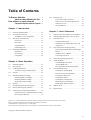
Table of Contents
To Ensure Safe Use .......................................... 2
About the Labels Affixed to the Unit ..... 5
Pour utiliser en toute sécurité ................... 6
À propos des étiquettes collées sur l'appareil ... 9
2-10 Powering Off .................................................... 37
Power Off in Daily Operation .................... 37
When Not Use for a Prolonged Period ....... 37
When Not in Use ........................................ 38
Storing Material .......................................... 38
Chapter 1 - Introduction
1-1
1-2
1-3
1-4
Checking Supplied Items ................................. 10
Set-up and Connections .................................... 11
For IBM PC or PC compatibles .................. 12
Part Names and Functions ................................ 13
Front View .................................................. 13
Rear View ................................................... 14
Operation Panel .......................................... 15
LED Display List ........................................ 16
Installing the DRIVER ..................................... 17
Installation .................................................. 18
Driver Setup ................................................ 19
Using Help .................................................. 20
Chapter 2 - Basic Operation
2-1
2-2
2-3
2-4
2-5
2-6
2-7
2-8
2-9
Installing a Blade .............................................. 21
Powering On ..................................................... 23
Loading the Material ........................................ 24
To Perform Long Printing/Cutting ............. 29
Cut Test ............................................................ 30
Installing a Ribbon Cartridge ........................... 31
Selecting Ribbon Cartridges ....................... 31
Installing Ribbon Cartridge ........................ 32
Replacing an Ink Cartridge ......................... 33
Self-test ............................................................ 34
Downloading Printing/Cutting Date ................ 35
Pausing and Stopping Operation ...................... 35
Cutting Off or Detaching the Material ............. 36
Cutting Off a Piece of Material from a Roll 36
Removing the Material ............................... 36
Chapter 3 - User's Reference
3-1
3-2
3-3
3-4
3-5
3-6
3-7
3-8
3-9
Settings for the PC-600 Driver for Windows ... 39
Settings (Making Settings on the PC-600) ....... 43
Other Functions ................................................ 45
Setting the Base Point ................................. 45
Setting the Crop Marks, Base Point, and
Align Point .................................................. 46
Tips and Tricks for Printing/Cutting ................ 47
Removing the Blank Space Surrounding a
Picture ......................................................... 47
Adding Color to a Border ........................... 47
Correcting Line Pitch ................................. 48
About the Printing/Cutting Area ...................... 49
About the Blade ................................................ 50
If the Blade Becomes Dull ......................... 50
Average Blade Life ..................................... 50
How to Replace the Separating Knife ........ 51
Care and Maintenance ...................................... 52
Cleaning the Printing Head ........................ 52
How to Use the Cleaning Sheet .................. 53
Cleaning the Main Unit .............................. 54
Cleaning the Platen ..................................... 54
Cleaning the Cleaning Pad ......................... 55
Replacing the Cleaning Pad ........................ 55
Cleaning the Reflective Panel .................... 55
What to Do If... ................................................ 56
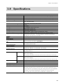
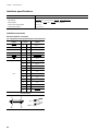
Specifications ................................................... 61
Windows® is a registered trademark or trademark of Microsoft Corporation in the United States and/or other countries.
IBM is a registered trademark of International Business Machines Corporation.
COLORCHOICE® is registered in the U. S. Patent Office.
Other company names and product names are trademarks or registered trademarks of their respective holders.
Copyright © 2000 Roland DG Corporation
1
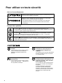
To Ensure Safe Use
About
and
Notices
Used for instructions intended to alert the user to the risk of death or severe
injury should the unit be used improperly.
Used for instructions intended to alert the user to the risk of injury or material
damage should the unit be used improperly.
* Material damage refers to damage or other adverse effects caused with
respect to the home and all its furnishings, as well to domestic animals or
pets.
About the Symbols
The
symbol alerts the user to important instructions or warnings. The specific meaning of
the symbol is determined by the design contained within the triangle. The symbol at left means
"danger of electrocution."
The
symbol alerts the user to items that must never be carried out (are forbidden). The
specific thing that must not be done is indicated by the design contained within the circle. The
symbol at left means the unit must never be disassembled.
The
symbol alerts the user to things that must be carried out. The specific thing that must
be done is indicated by the design contained within the circle. The symbol at left means the
power-cord plug must be unplugged from the outlet.
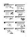
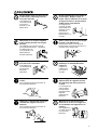
Do not disassemble, repair, or
modify.
Doing so may lead to fire or abnormal
operation resulting in injury.
Ground the unit with the ground
wire.
Failure to do so may result in risk of
electrical shock in the even of a mechanical
problem.
2
Do not use with any electrical power
supply that does not meet the
ratings displayed on the unit.
Use with any other power supply may lead
to fire or electrocution.
Do not use while in an abnormal
state (i.e., emitting smoke, burning
odor, unusual noise, or the like).
Doing so may result in fire or electrical
shock.
Immediately switch off first the sub power,
then the main power, unplug the power cord
from the electrical outlet, and contact your
authorized Roland DG Corp. dealer or
service center.
Do not use with a damaged power
cord or plug, or with a loose
electrical outlet.
Use with any other
power supply may
lead to fire or
electrocution.
Do not injure or modify the electrical
power cord, nor subject it to
excessive bends, twists, pulls,
binding, or pinching, nor place any
object of weight on it.
Doing so may
damage the
electrical power
cord, leading to
electrocution or
fire.
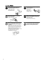
When not in use for extended
periods, unplug the power cord from
the electrical outlet.
When unplugging the electrical
power cord from the power outlet,
grasp the plug, not the cord.
Failure to do so may
result in danger of
shock, electrocution,
or fire due to
deterioration of the
electrical insulation.
Unplugging by pulling the cord may damage
it, leading to fire or electrocution.
Do not attempt to unplug the power
cord with wet hands.
Do not allow liquids, metal objects
or flammables inside the machine.
Doing so may
result in electrical
shock.
Such materials
can cause fire.
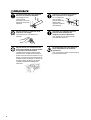
Install in a level and stable location.
Unpacking, installing, or relocating
the unit are operations which must
be carried out by two or more persons holding the unit at its bottom
surface on the left and right sides.
Otherwise the unit may tip over and cause
injury.
Failure to do so may
result in dropping
the unit, leading
to injury.
Release the caster locks for the
stand before attempting to move.
Otherwise the unit may tip over and cause
injury.
Use care to avoid pinching the
fingers when placing the unit on the
stand.
Doing so may
result in injury.
3
Roll material must be placed at a
predetermined shaft position.
Use the joining screws to secure the
unit to the stand.
Failure to do so may
result in falling of the
roll, leading to injury.
Failure to do so
may result in
falling of the unit,
leading to injury.
Do not touch the tip of the blade
with your fingers.
Make sure the power to the unit is
off before attempting to replace the
separating knife.
Doing so may result in injury.
Doing so may result in injury.
Do not allow hands or hair to come
near the platen while the carriage is
in motion.
Failure to do so may result in injury due to
sudden movement of the carriage when the
power is switched on/off, when the sheet
loading lever is raised or lowered,
or when the [CUT TEST] key, [SHEET CUT]
key, [DATA CLEAR] key, or [HEAD
CLEANING] key is pressed.
4
Do not touch the area around the
printing carriage with the hands.
Failure to do so may result in burns.
About the Labels Affixed to the Unit
These labels are affixed to the body of this product.
The following figure describes the location.
Do not allow hands or hair to come near the platen while
the carriage is in motion.
Do not touch the area around the
printing carriage with the hands.
Model name
Rating label
Use a rated power supply.
In addition to the
NOTICE
and
symbols, the symbols shown below are also used.
: Indicates information to prevent machine breakdown or malfunction and ensure correct use.
: Indicates a handy tip or advice regarding use.
5
Pour utiliser en toute sécurité
Avis sur les avertissements
Utilisé pour avertir l'utilisateur d'un risque de décès ou de blessure grave en
cas de mauvaise utilisation de l'appareil.
Utilisé pour avertir l'utilisateur d'un risque de blessure ou de dommage
matériel en cas de mauvaise utilisation de l'appareil.
* Par dommage matériel, il est entendu dommage ou tout autre effet
indésirable sur la maison, tous les meubles et même les animaux
domestiques.
À propos des symboles
Le symbole
attire l'attention de l'utilisateur sur les instructions importantes ou les
avertissements. Le sens précis du symbole est déterminé par le dessin à l'intérieur du triangle.
Le symbole à gauche signifie "danger d'électrocution".
Le symbole
avertit l'utilisateur de ce qu'il ne doit pas faire, ce qui est interdit. La chose
spécifique à ne pas faire est indiquée par le dessin à l'intérieur du cercle. Le symbole à
gauche signifie que l'appareil ne doit jamais être démonté.
Le symbole
prévient l'utilisateur sur ce qu'il doit faire. La chose spécifique à faire est
indiquée par le dessin à l'intérieur du cercle. Le symbole à gauche signifie que le fil électrique
doit être débranché de la prise.
Ne pas démonter, réparer ou
modifier.
Le non-respect de cette consigne pourrait
causer un incendie ou provoquer des
opérations anormales entraînant des
blessures.
Mettre l'appareil à la masse avec une
prise de terre.
Le non-respect de cette consigne pourrait
entraîner des décharges
électriques en
cas de problème mécanique.
6
Ne pas utiliser avec une alimentation
électrique ne respectant pas les
caractéristiques indiquées sur
l'appareil.
Une utilisation avec toute autre alimentation
électrique pourrait provoquer un incendie
ou une électrocution.
Ne pas utiliser si l'appareil est dans
un état anormal (c'est-à-dire s'il y a
émission de fumée, odeur de brûlé,
bruit inhabituel etc.).
Le non-respect de cette consigne pourrait
provoquer un incendie ou des décharges
électriques.
Couper immédiatement l'alimentation
secondaire et ensuite l'alimentation
principale. Débranchez le fil électrique et
contacter votre revendeur ou votre centre
de service de la société Roland DG
autorisé.
Ne pas utiliser avec une fiche ou un
fil électrique endommagé ou avec
une prise mal fixée.
Une négligence à
ce niveau pourrait
provoquer un
incendie ou une
électrocution.
Débrancher le fil lorsque l'appareil
reste inutilisé pendant une longue
période.
Une négligence à ce niveau pourrait
provoquer des décharges électriques,
une électrocution ou
un incendie dû à une
détérioration de
l'isolation électrique.
Ne pas essayer de débrancher le fil
avec des mains mouillées.
Une négligence à
ce niveau pourrait
provoquer des
décharges
électriques.
Installer dans un endroit stable et de
niveau.
Sinon l'appareil pourrait se renverser et
provoquer des blessures.
Ne pas endommager ou modifier le
fil électrique. Ne pas le plier, le
tordre, l'étirer, l'attacher ou le serrer
de façon excessive. Ne pas mettre
d'objet ou de poids dessus.
Une négligence à
ce niveau pourrait
endommager le fil
électrique ce qui
risquerait de
provoquer une
électrocution ou un
incendie.
Saisir la fiche et non le fil électrique
lorsque vous débranchez.
Débrancher en tirant sur le fil pourrait
l'endommager et risquer de provoquer un
incendie ou une électrocution.
Ne pas introduire de liquide, d'objet
métallique ou inflammable dans
l'appareil.
Ce genre de
matériel peut
provoquer un
incendie.
Le déballage, l'installation et le
déplacement de l'appareil doivent
être effectués par deux personnes
ou plus.
Le non-respect de
cette consigne
pourrait causer
des défauts dans
l'appareil
entraînant des
blessures.
Débloquer le mécanisme d'arrêt des
roulettes du support avant de le
déplacer.
Sinon l'appareil pourrait se renverser et
provoquer des blessures.
Manipuler avec précaution pour
éviter de se coincer les doigts lors
de l'installation de l'appareil sur le
support.
Une négligence à
ce niveau pourrait
provoquer des
blessures.
7
Le rouleau doit être placé quand la
barre est en position adéquate.
Utiliser les vis fournies pour bien
fixer l'appareil sur le support.
Une négligence à ce
niveau pourrait
provoquer la chute du
rouleau et causer des
blessures.
Le non-respect de
cette consigne
pourrait causer des
défauts dans
l'appareil entraînant
des blessures.
Ne pas toucher à l’extrémité de la
lame avec vos doigts.
S'assurer que l'appareil est hors
tension avant d'essayer de
remplacer la lame séparatrice.
Vous risqueriez de vous blesser en y
touchant.
8
Une négligence à ce niveau pourrait
provoquer des blessures.
Ne pas laisser vos cheveux ou vos
mains à proximité du rouleau quand
le chariot est en mouvement.
Ne touchez pas avec les mains la
zone située autour du chariot d'
impression.
Le défaut de ce faire peut entraîner des
blessures dues au déplacement rapide du
chariot lors de la mise sous tension ou hors
tension, lorsque le levier de chargement de
la feuille est levé ou abaissé, ou lorsque les
clés [CUT TEST], [SHEET CUT], [DATA
CLEAR] ou [HEAD CLEANING] sont
enfoncées.
Tout manquement à cette consigne pourrait
provoquer des brûlures.
À propos des étiquettes collées sur l'appareil
Ces étiquettes sont collées à l'extérieur de l'appareil.
Les dessins suivants indiquent l'endroit et le contenu des messages.
N' approchez pas vos mains ni vos cheveux du plateau
de travail quand le chariot est en mouvement.
Ne touchez pas avec les mains la zone
située autour du chariot d' impression.
Nom du modèle
Étiquette des caractéristiques
électriques
Utiliser l'alimentation appropriée
9
Chapter 1 - Introduction
Chapter 1 - Introduction
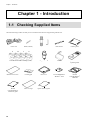
1-1 Checking Supplied Items
Check the following to make sure that you received all the items that were shipped along with the unit.
Pin
Power cord
C
Blade (carbide)
M
Y
Blade holder
Head cleaner
Cleaning sheet
Alignment tool
Brake
Replacement blade for
separating knife
Cleaning pad
Dust cover
PC-600 DRIVER for
Windows® 98/95
Roland
COLORCHOICE®
CD-ROM
Notes on usage
Quick reference guide
K
Thermal transfer ribbon cartridge (resin)
Material for test cuts
Roland
COLORCHOICE®
installation guide
10
Chapter 1 - Introduction
1-2 Set-up and Connections
Ground the unit with the ground
wire.
Failure to do so may result in risk of
electrical shock in the even of a mechanical
problem.
Unpacking, installing, or relocating
the unit are operations which must
be carried out by two or more persons holding the unit at its bottom
surface on the left and right sides.
Do not use with any electrical power
supply that does not meet the
ratings displayed on the unit.
Use with any other power supply may lead
to fire or electrocution.
Install in a level and stable location.
Otherwise the unit may tip over and cause
injury.
Failure to do so may
result in dropping
the unit, leading
to injury.
NOTICE
Do not hold the upper portion of the PC-600 when installing or moving the unit.
Avoid installing the PC-600 in the following conditions, as this may result in damage to the machine.
• Avoid use in locations subject to high levels of electrical noise (near motors, generators, transformers, and
the like).
• Avoid use in locations subject to high humidity or dust.
• The unit becomes hot during use. Do not install in locations where heat radiation is inadequate (i.e., areas
with poor ventilation).
• Do not install in locations subject to strong vibration.
• Do not install in a location exposed to direct sunlight or other strong light.
• Install in an environment having a suitable operating temperature and humidity.
Always make sure that the main power switch is switched off on both the computer and the PC-600 whenever
any cables are connected or disconnected.
Do not put the hands inside the left and right covers. Doing so may result in breakdown of the unit.
Do not touch the reflective panel with the hands.
If the reflective panel is soiled, it may become impossible to replace the ink-ribbon cartridge correctly.
11
Chapter 1 - Introduction
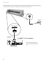
When arranging setup space for the PC-600, make sure you have a space that is at least 1500 mm (59-1/16 in.) wide, 750 mm (29-9/16
in.) in depth, and 1500 mm (59-1/16 in.) in height. Since the material moves during printing and cutting, make sure the unit is placed on a
stable, sturdy surface. Also make sure there is nothing that can block the material at both front and rear.
Power connector
Power outlet
Power cord
Parallel input connector
Parallel interface Cable
(IEEE1284)
For IBM PC or PC compatibles
Parallel
connector
12
* The cable for computer connection is
optional. Please purchase the appropriate
cable for the type of computer and software
used.
Chapter 1 - Introduction
1-3 Part Names and Functions
Front View
Printing carriage
Front cover
This is where a ribbon cartridge is mounted in
the cartridge holder and printing is carried out.
Opening the front cover during printing or cutting causes operation to be
paused. Operation resumes when the front cover is closed.
No printing or cutting is performed while the front cover is opened.
When the front cover is closed, the unit detects the color and location of
the installed ribbon cartridge.
Pinch roller (left)
Press material against the grit
roller. When loading material,
place the left roller inside the
left edge of the material to
correctly track it through the
machine.
Cleaning pad
Separating knife
This cuts off a piece of material from rolled material.
Cutting carriage
The blade holder is mounted here.
Cartridge holder
* Do not remove this pad
except to replace it.
Removing it may
result in breakdown.
This is where the ribbon cartridge is installed.
Pinch roller (right)
This presses the material against the grit roller.
Reflective
panel
Tray
Use this to store
blades or pens.
Material
alignment sticker
Platen
Knife guide
Plate slide
Grit roller
Operation panel
Grit roller position indicator
13
Chapter 1 - Introduction
Rear View
Sheet Loading Lever
Used to raise or lower the pinch rollers
when loading or unloading material.
Automatic setup is performed by loading
material and lowering the lever.
Power Connector (AC IN)
This connector accepts standard AC
power cord.
Parallel (centronics) input connector
In a parallel configuration, connect the parallel cable here.
This cable carries data to your computer.
14
Main Power Switch
Chapter 1 - Introduction
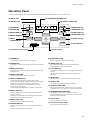
Operation Panel
* "Material setup" refers to the state when material has been loaded and the sheet-loading lever has been lowered.
12) BUSY LED
15) CARTRIDGE HOLDER LED
13) SETUP LED
14) FRONT COVER LED
1) POWER key
6) BASE POINT key
7) BASE POINT LED
2) POWER LED
8) ALIGN POINT key
9) ALIGN POINT LED
3) DATA CLEAR key
4) DATA CLEAR LED
10) SHEET CUT key
5) HEAD
CLEANING key
11) CUT TEST key
17) Tool force control slider
1) POWER key
This switches the sub power source on and off.
2) POWER LED
This lights up when the sub power source has been switched
on.
3) DATA CLEAR key
Holding down this key until a beep is heard deletes the data
being received.
4) DATA CLEAR LED
The LED flashes while data is being deleted.
5) HEAD CLEANING key
This performs forced cleaning of the printing heads.
The PC-600 automatically performs cleaning of the printing
heads. There is normally no need to perform forced
cleaning. Press this key to perform cleaning only when
printing is especially grimy.
To start cleaning, hold down the key until a beep is heard.
6) BASE POINT key
Sets the current position of the blade to the base point for
printing or cutting.
This key can be used only after material has been loaded.
Hold down the key until a beep is heard.
7) BASE POINT LED
16) Cursor keys
9) ALIGN POINT LED
Setting a align point illuminates this LED.
10) SHEET CUT key
This separates the printed or cut portion from the roll.
Hold down the key until a beep is heard.
11) CUT TEST key
This performs a cutting test (for verifying that blade force is
correct).
This key can be used only after material setup has been
performed.
12) BUSY LED
This flashes while receiving data and during processing.
13) SETUP LED
This lights up when material setup is finished.
14) FRONT COVER LED
During setup, this flashes when the front cover is opened.
Closing the front cover causes it to remain lit continuously.
15) CARTRIDGE HOLDER LED
This lights up when a ribbon cartridge is installed.
It flashes when the cartridge is installed incorrectly or the
ink ribbon has been used up.
16) Cursor keys
Move the material and carriage.
Setting a base point illuminates this LED.
8) ALIGN POINT key
17) Tool force control slider
This is used to set the blade force.
This sets an align point for correcting the slant of loaded
material.
Hold down the key until a beep is heard.
15
Chapter 1 - Introduction
LED Display List
: Lights up
: Flashing
–
: Dark
LED state
POWER SETUP
PC-600 status and operator action
CARTRIDGE
FRONT DATA BASE ALIGN
BUSY
HOLDER
COVER CLEAR POINT POINT
–
–
–
–
–
–
–
–
–
–
–
–
–
–
The sub power is on.
For information about canceling sleep state -> sleep state, see "2-2
Powering On Auto-sleep."
The unit is installed in a location outside the operating-temperature
range.
–
–
–
–
–
–
–
–
–
–
–
–
–
–
–
–
–
–
–
–
>> Install in a location where the operating temperature is
appropriate. (See "3-9 Specifications Operating Temperature.")
Material setup has finished and operation is possible.
The pinch roller is above the grit roller.
The loaded material is displaced from the sensor.
>> See "2-3 Loading the Material".
The cartridge set the corresponding location is installed incorrectly.
Corresponding
LED is
–
–
>> Install the ink-ribbon cartridge correctly.
–
–
–
–
–
(See "2-5 Installing a Ribbon Cartridge".)
The ink ribbon at the corresponding location has been used up.
>> Install a new ribbon cartridge of the same color. (See "2-5
Installing a Ribbon Cartridge Replacing an Ink Cartridge".)
–
–
–
–
–
–
–
The corresponding cartridge is installed correctly.
- Ink-ribbon cartridges have been installed at the six cartridgeholder locations, and at the printing carriage.
All
(1 through 6)
–
–
–
–
–
–
- During printing, the carriage could not retrieve an ink-ribbon
cartridge, or could not return a cartridge to the cartridge holder.
>> Install the ink-ribbon cartridge correctly. (See "2-5 Installing a
Ribbon Cartridge.")
All
(1 through 6)
–
–
–
–
–
–
–
–
–
–
–
A ribbon cartridge need for printing is absent.
–
–
–
–
–
–
–
–
While receiving data and during processing
–
–
–
–
The front cover is closed.
–
–
–
–
–
The front cover is open (operation is paused).
–
–
–
–
–
–
Data is being deleted.
–
–
–
–
–
–
–
The origin point for printing or cutting was set.
–
–
–
–
–
–
–
>> Install the ribbon cartridge that is needed for printing. (See "2-5
Installing a Ribbon Cartridge".)
16
The setting for axis calibration has been made.
Chapter 1 - Introduction
1-4 Installing the DRIVER
The screens shown in these steps are for windows 95. These screens may differ in places from the screens for windows 98, but the steps
themselves are identical.
- To perform printing or cutting from a software application, the appropriate software driver must be installed.
- The file Readme.txt on the driver-installation disk contains late-breaking information that is not in the manual. Be sure to read through
this file.
You can read this file using Notepad or another word processor.
Operating environment
Personal computer with Windows® 98 or Windows® 95 installed.
Supported model
Color CAMM PRO PC-600
17
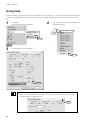
Chapter 1 - Introduction
Installation
1
Switch on the computer and start windows®.
2
Insert the "PC-600 DRIVER for Windows® 98 / 95"
disk included with the unit.
3
Click [Start].
Point to [Settings], then click [Printers].
4
Double-click the [Add Printer] icon.
Double-Click
Click
5
Click [Next >] and follow the messages to complete
installation of the driver.
Click
18
Chapter 1 - Introduction
Driver Setup
Use the driver to choose the output port for data.
1
2
Click [Start].
Point to [Settings], then click [Printers].
Click the right mouse button on [Roland PC-600]
and select [Properties].
Click the right mouse
Click
Click
3
Click the [Details] tab and select a port.
Select "LPT1: (Printer Port)".
Click
If you're using a serial connection, click [Port Settings...]
and make the settings for the communication parameters.
19
Chapter 1 - Introduction
Using Help
If there is something you're not sure about or don't understand when setting up the driver, you can refer to the help screens for that topic.
Available topics include details of the various settings as well as the "Printing and Cutting Guide" and "If you Think There's a Problem...."
1
2
Click [Start].
Point to [Settings], then click [Printers].
Click the right mouse button on [Roland PC-600]
and select [Properties].
Click the right mouse
Click
3
Click the [Size] tab, then click [Help...].
Click
Click
Clicking [?] in the upper-right corner of the window makes the mouse pointer change to a question
mark ("?"). You can then move the "?" pointer over any item you wish to learn more about, then click
on the item to display an explanation of it.
Click
20
Chapter 2 - Basic Operation
Chapter 2 - Basic Operation
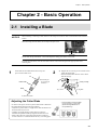
2-1 Installing a Blade
NOTICE
When installing or removing a blade, make sure the sub power for the PC-600 is switched off and no material is
loaded.
When mounting the blade holder, do not depress the plate slide.
Plate slide
Do not touch the tip of the blade. This could impair the cutting performance of the blade.
To mount the tool holder, insert the tool holder until its collar lies flush against the upper portion of the
mounting hole.
1
Insert blade into the blade holder until it snaps into
place with an audible click.
Pin
Blade holder
2
2) Support the tool-securing screw from below and
install the blade holder.
* Insert the blade holder until the collar is flush
with the carriage.
1) Insert the pin.
(Leave the pin
inserted.)
Blade
Cutting carriage
1) Loosen
3) Tighten
2) Insert the blade.
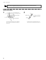
Adjusting the Cutter Blade
As shown in the figure, turn the tip of the blade holder to determine
the optimal blade amount for the target material.
- Adjust the tip of the blade to a length shorter than the thickness of
the sheet (material) to be cut.
- Gradually extend the blade tip while doing test cutting to
determine the optimum blade tip length for the sheet to be cut.
- When cutting becomes impossible under identical conditions,
increase tool force or extend the blade and carry out cutting again.
* One full rotation moves the blade
0.5 mm (0.0197 in.) up or down.
(Scale shows gradations of 0.1
mm (0.00394 in.))
21
Chapter 2 - Basic Operation
When cutting is performed after printing, the cap tip of the blade holder may scratch the printed surface.
If this is the case, lengthen the cutter blade extension.
Removing a Blade
1
2) Remove the blade holder from
the cutting carriage.
Cutting carriage
2
Pin
Blade holder
1) Loosen
Tool-securing screw
Leave the tool-securing screw loose. Tightening
the screw makes it more difficult to install the
blade holder.
22
Press the pin and remove
the blade from the blade
holder.
Blade
If a blade was used, wipe the blade with a soft
cloth to remove any material that may cling to it.
Chapter 2 - Basic Operation
2-2 Powering On
Do not allow hands or hair to come
near the platen while the carriage is
in motion.
Failure to do so may result in injury due to
sudden movement of the carriage when the
power is switched on/off, when the sheet
loading lever is raised or lowered,
or when the [CUT TEST] key, [SHEET CUT]
key, [DATA CLEAR] key, or [HEAD
CLEANING] key is pressed.
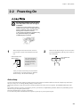
1
When using the unit for the first time, switch on
the main power switch on the left-hand side of the
unit.
Press the side of the
switch marked “ –”.
Leave the main power
switch on, and use the
sub power switch for
switching the unit on
and off on an everyday basis.
2
Make sure the sheet loading levers are raised, then
press the [POWER] key (the sub power switch) on
the control panel.
The POWER LED
lights up
After you switch on the main power, the machine
spends about five seconds warming up. When the
machine beeps, it has finished warming up.
Auto-sleep
You can set the interval after printing or cutting operation, panel operation, and data transmission from the computer stop until the PC600 goes to sleep (see "3-2 Setting (Making Settings on the PC-600)").
When the PC-600 goes to sleep, the sub power switches off and the unit enters power-saving mode. The POWER LED flashes at this
time.
The available settings are [30 min.] (30 minutes), [60 min.] (60 minutes), and [DISABLE] (disabled). When set to [DISABLE], the PC600 does not go to sleep after operation stops.
The factory-default setting is [30 min.] (30 minutes).
To cancel the sleep mode, send data from the computer or press any key on the operation panel.
23
Chapter 2 - Basic Operation
2-3 Loading the Material
Do not allow hands or hair to come
near the platen while the carriage is
in motion.
Roll material must be placed at a
predetermined shaft position.
Failure to do so may
result in falling of the
roll, leading to injury.
Failure to do so may result in injury due to
sudden movement of the carriage when the
power is switched on/off, when the sheet
loading lever is raised or lowered,
or when the [CUT TEST] key, [SHEET CUT]
key, [DATA CLEAR] key, or [HEAD
CLEANING] key is pressed.
NOTICE
Please do not try to move the tool
carriage by hand once the power
has been turned on. Doing so may
result in breakdown of the unit.
Not OK
Actions such as the following must never be attempted, because they may lead to damage of the printing head.
Do not attempt to print on a material that has grit-roller marks.
Not OK
Grit-roller mark
Do not attempt to print at a location where cutting has been performed (such as an
area used for a cutting test).
Not OK
Cutting-test area
Do not use material that is dusty or scratched.
Ink adhesion may suffer if the material's printing surface is not clean. If dirt, oils from the hand, or dusts are
transferred to the material when it is loaded, use a cloth moistened with alcohol to wipe the material clean
before printing.
24
Chapter 2 - Basic Operation
1
* Only when using rolled material
Pass the stopper onto the shaft to match the width of
the roll material to be used. (The shafts (2 pieces),
stoppers (2 pieces), and stopper retaining screws (2
pieces) are included with the stand.)
Stopper retaining screws
Shaft
When fitting the stoppers onto the shaft, loosen the
stopper retaining screws and pass the stoppers onto
the end of the shaft where the hole is present.
Stopper
Stopper
2
Set the two shafts in place and attach the brake.
Brake
Screw
Move the brake toward the shaft
OK
Rear view
Not OK
Shaft
3
Sheet hanger
Install the two shafts on the sheet hanger and place
the roll material on top of the shafts.
When you are using roll material, make the setting
on the PC-600 to set the prefeed function to
[ENABLE] (the factory default is [ENABLE]).
Before performing printing or cutting, the length of
material required for output is automatically pulled
out from the roll, then returned to the rear, where it
is left slack. If output is performed without carrying
out this operation first, printing or cutting may be
misaligned, or the material may come loose or jam.
If the setting for disabling the prefeed function has
been made on the machine, then pull out from the
roll the length of material required.
(If the prefeed function is enabled, there is no need
to pull out material.)
Sheet hanger
Sheet hanger
Shafts
Front
Stoppers
Rear
25
Chapter 2 - Basic Operation
Side view of loaded roll material
When using a thick roll of
material
Shafts
4
When only a small amount
of material remains
(material diameter is 72
mm (2-7/8 in.) or less)...
Not OK
Shafts
Shafts
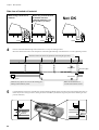
Position so that the left-hand edge of the material lies over any one of the grit rollers.
Move the material from side to side and position so that the right-hand edge of the material lies over the rightmost grit roller.
The holes on the rail portion are guides for positioning the grit rollers.
Rear sensor
Grit roller (right)
Front sensor
Cleaning pad
Make sure any objects are not over the cleaning pad.
Damage to the head may result.
5
Load the material so that it lies straight and is aligned with the guideline stickers, then move the left and right pinch rollers so
that at they are above the grit rollers. (If the grit rollers are hidden by the material, align the pinch rollers with the grit roller
position indicators.)
Material
alignment
stickers
26
Make sure the material lies
over the front and rear sensors.
Material
alignment
stickers
Chapter 2 - Basic Operation
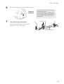
6
Lower the sheet loading levers to secure the material in place.
Setup is
finished.
7
* Only when using rolled material
When the sheet loading lever is lowered, the
carriage begins to move.
The width of the material is detected, and the
carriage stops at the material's right-hand edge.
When no setting is made for BASE POINT,
the point where the unit stops here becomes
the base point.
Roll material
Attach the stoppers to the edges of the roll material
and tighten the screws to secure in place.
Stopper retaining screw
27
Chapter 2 - Basic Operation
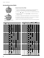
Loadable material widths and pinch-roller positions
: Grit roller
: Pinch roller (left)
: Pinch roller (right)
Approx.160 mm
(6-1/4 in.)
Approx.320 mm
(12-9/16 in.)
Material
Approx.460 mm
(18-1/16 in.)
Approx.610 mm
(24 in.)
Position of the
pinch roller (left) for
material with a
width of 610 mm
(24 in.)
Position of the
pinch roller (left) for
material with a
width of 460 mm
(18-1/16 in.)
Position of the
pinch roller (left) for
material with a
width of 320 mm
(12-9/16 in.)
Position of the
pinch roller (left) for
material with a
width of 160 mm (61/4 in.)
Make sure the pinch rollers are positioned above the grit rollers
Approx.160 mm
(6-1/4 in.)
The right-hand movable pinch roller can be
moved within this range. When loading material
with a width other than one indicated above,
move the right-hand movable pinch roller.
If the SETUP LED flashes
Possible causes are given below.
The pinch rollers are not above the grit rollers.
Refer to "2-3 Loading the Material" and position the pinch rollers correctly above the grit rollers.
The loaded material does not cover the front and rear sensors.
Refer to "2-3 Loading the Material" and position the material correctly over the front and rear sensors.
28
Chapter 2 - Basic Operation
To Perform Long Printing/Cutting
When performing printing or cutting over a length of 1 m (39-3/8 in.) or more, first feed out the required length of material. Then follow
the steps below to load the material.
If the setting for enabling the prefeed function has been made on the PC-600, then skip steps 6 and 7.
1
Use material that is wider by 50 mm (2 in.) or more
than the width of the printing or cutting to be
performed.
3
Position the pinch rollers as shown in the figure.
2
Perform steps 1 through 3 of "2-3 Loading the
Material".
25 mm
(1 in.)
or more
25 mm
(1 in.)
or more
Material
alignment
stickers
4
Lower the sheet loading levers to secure the material
in place.
Material
alignment
stickers
5
Attach the stoppers to the edges of the roll material
and tighten the screws to secure in place.
Roll material
Stopper retaining screw
6
Feed out the length of material to be printed or cut.
Make sure that the
material remains held by
the pinch rollers.
If the material does come
loose from the pinch
rollers, set it in place
again.
7
Return the fed-out material.
Make sure the
material lies over the
front and rear sensors.
When you are performing long printing, expansion or contraction of the material may cause colors to be misaligned.
For roll material in particular, the time required for the material to uncurl and acclimatize to the ambient temperature
and humidity is different for the outer portions and the central portion of the roll.
Before you perform long printing, pull out the length of material to be printed from the roll and let it allow to stand for
about 30 minutes to an hour to allow it to become acclimatized to the environment, then load the material.
29
Chapter 2 - Basic Operation
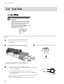
2-4 Cut Test
Do not allow hands or hair to come
near the platen while the carriage is
in motion.
Failure to do so may result in injury due to
sudden movement of the carriage when the
power is switched on/off, when the sheet
loading lever is raised or lowered,
or when the [CUT TEST] key, [SHEET CUT]
key, [DATA CLEAR] key, or [HEAD
CLEANING] key is pressed.
When carrying out cutting for the first time, or when the material or tool has been changed, a cutting test is performed to verify how the
tool cuts.
1
Move the tool force control slider on the right-hand
side of the unit all the way to the front (for minimum blade force).
2
Open the front cover and move the tip of the blade
to the point where the cutting test is to be started.
3
Hold down the [CUT TEST] key until you hear a
beep.
Cut test starts.
* Note that an area of approximately 2 square centimeters (a
little less than a square inch) is required to make a test cut.
4
1) First peel off the round section (shaded as shown ).
>> When it can be peeled by itself, without disturbing the square, the cutter
force is set appropriately.
2) Next, peel off the square, and look at the backing behind it.
>> The optimum blade pressure is correct if you can clearly make out the
lines left by the blade.
Peel off first
Then peel
this off
Origin
Use the tool force control slider to adjust the blade force so that results like
those shown above are not obtained.
Gradually increase the cutter force until you reach the optimum level.
30
Chapter 2 - Basic Operation
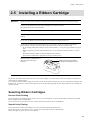
2-5 Installing a Ribbon Cartridge
NOTICE
Ribbon cartridges must be installed in cartridge holders, and not mounted directly on the printing carriage.
Do not allow the marker seals on the ribbon cartridges to be soiled or scratched.
Such damage may result in faulty operation.
When performing full-color printing, install ribbon cartridges for four colors (CMYK).
When closing the front cover, close gently by pressing with the hand, being careful not to let your fingers get
pinched.
Do not allow the hands to touch the ink ribbons when opening or closing the front cover.
The PC-600 can perform printing using either resin or wax ribbons. Please give attention to the matters
described below. Failure to do so may make it impossible to achieve attractive printing results.
• Do not attempt printing with a mixture of resin and wax ribbons. Use only one type of ribbon at any given
time.
• Make sure that the type of ink ribbon installed (resin or wax) matches the setting for the driver (resin or
wax).
• Resin ribbons and wax ribbons are suited to different types of media.
Please select a medium that is appropriate for the type of ribbon in use.
Please do not use a cartridge when it
shows the ribbon end stripe as
illustrated.
Ribbon end stripe (The condition
shows when the ink ribbon ran out.)
The PC-600 can automatically determine the color of an ribbon cartridge, so it doesn't matter which color cartridges are mounted in
which of the six cartridge holders.
Also, when more than one ribbon cartridge of the same color have been installed, the unit gives priority to the leftmost cartridge as seen
from the front. In such cases, if the first cartridge runs out of ink ribbon during printing, the unit simply selects the next cartridge and
continues printing.
Selecting Ribbon Cartridges
Process Color Printing
Full-color printing is performed using the process colors C (cyan), M (magenta), Y (yellow), and K (black). Install the four CMYK
ribbon cartridges in the cartridge holders.
For the software driver, select Process Colors. (Please refer to the help file for the PC-600 DRIVER.)
Special Color Printing
This is used when you wish to add emphasis to one area or perform printing with limited colors.
For the software driver, select Special Colors. (Please refer to the help file for the PC-600 DRIVER.)
Ribbon cartridges for special colors are sold separately.
31
Chapter 2 - Basic Operation
Installing Ribbon Cartridge
1
2
When installing a new ribbon cartridge, remove the
stopper.
Take up slack in the in ribbon as shown in the
figure.
Side B
Turn with a
pencil or the
like
- Do not attempt to rewind the ink ribbon.
Rewinding the ink ribbon may cause it to break.
- A used ribbon cartridge cannot be reused.
Do not attempt to turn over and reinstall a
used ribbon cartridge, or to rewind the ink
ribbon and reuse the cartridge.
3
Open the front cover and fit the cartridge in the cartridge holder. Gently press into place with the fingers.
Make sure side B is facing up.
The cartridge is held in place by the tabs
on the left and right.
Make sure that the cartridge is securely
held in place by the tabs on the left and
right sides, and that the ink ribbon is
free of slack.
1
2
3
4
5
6
From left to right, as shown in the figure, the
CARTRIDGE HOLDER LED numbers
correspond to cartridge holders 1 through 6,
and the LEDs for holders where ink-ribbon
cartridges are installed light up. If a cartridge
is not installed correctly, the LED lights up
and a warning beep sounds. (To disable the
warning beep, on the machine, set Beep
(warning beep for the ink-ribbon cartridges)
to [Disable] (see "3-2 Settings (Making
Settings on the PC-600).")
4
Gently close the front cover.
The FRONT COVER LED flashes if the
front cover is not shut securely.
Make sure the LED is lighted.
32
Chapter 2 - Basic Operation
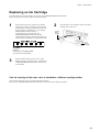
Replacing an Ink Cartridge
If an ink ribbon runs out while printing is in progress, the CARTRIDGE HOLDER LED flashes.
Follow the steps below to replace with a new ribbon cartridge.
1
If the ink ribbon runs out, operation stops and the
warning beep sounds. (To disable the warning beep,
on the machine, set Beep (warning beep for the inkribbon cartridges) to [Disable] (see "3-2 Settings
(Making Settings on the PC-600).") )
If data is being received at this time, the
CARTRIDGE HOLDER LED for the holder
installed with the cartridge where the ink ribbon has
run out flashes simultaneously with the BUSY LED.
2
Open the front cover and replace with a new ribbon
cartridge of the same color.
Used-up
ribbon
cartridge
New
ribbon
cartridge
Example:
In this case, the cartridge installed
at "2" has run out of ink ribbon.
3
Printing resumes when the front cover is closed.
When a cartridge of a different color is installed, the
CARTRIDGE HOLDER LED flashes and printing
is not resumed.
If an ink cartridge of the same color is installed in a different cartridge holder
The cartridge of the same color is retrieved and printing continues.
However, the CARTRIDGE HOLDER LED continues to flash until the ink cartridge is replaced.
33
Chapter 2 - Basic Operation
2-6 Self-test
Do not allow hands or hair to come
near the platen while the carriage is
in motion.
Failure to do so may result in injury due to
sudden movement of the carriage when the
power is switched on/off, when the sheet
loading lever is raised or lowered,
or when the [CUT TEST] key, [SHEET CUT]
key, [DATA CLEAR] key, or [HEAD
CLEANING] key is pressed.
The PC-600 is equipped with a “self-test” function to allow you to check whether or not it is capable of operating normally. If the PC-600
is not performing correctly, follow the steps below to perform a self-test.
A computer is not required in order to carry out the self-test.
1
Leave on the main power for the PC-600, and
switch off the sub power.
2
Install blade holders and four-color (CMYK) ribbon
cartridges on the PC-600.
3
Hold down the key on the panel while you turn
the [POWER] key (sub power) on.
4
Load material and lower the sheet loading lever.
6
Operations is normal if the figure shown at below.
+
5
Gently close the front cover.
Cutting
Full-color
printing
Self-test starts.
Settings on the machine
After the operation check has finished, raising the sheet loading lever cancels the operation check mode. After that, the unit just as it
does when the power has been switched on in the normal manner.
34
Chapter 2 - Basic Operation
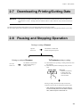
2-7 Downloading Printing/Cutting Date
NOTICE
When printing a line that is horizontal with respect to the direction of material feed, set the line width to 0.15
mm (0.0059 in.) or more. Printing with a line width less than 0.15 mm (0.0059 in.) may cause the ink ribbon to
snap.
The unit will begin printing/cutting when it receives printing/cutting data sent from the computer.
For more details, please refer to the help file for the PC-600 DRIVER or the documentation for the application software you're using.
2-8 Pausing and Stopping Operation
Printing or cutting is Paused
Open the
front cover.
Printing or cutting is Resumes
Close the
front cover.
The FRONT COVER LED
lights up and printing or
cutting resumes.
The FRONT COVER LED
flashes and operation pauses.
To Terminate printing or cutting
1) Halt transmission of printing or cutting instructions from
the computer.
2) Hold down the [DATA CLEAR] key until you hear a
beep.
LED status
Remains continuously
lit during data clear.
Goes dark when data
clear has ended.
Printing or cutting instructions already sent from the
computer to the PC-600 are deleted, and operation stops.
* After stopping an operation, if the unit does not
function normally when the next batch of data is
sent, switch the power off and back on.
35
Chapter 2 - Basic Operation
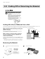
2-9 Cutting Off or Detaching the Material
Do not allow hands or hair to come
near the platen while the carriage is
in motion.
Failure to do so may result in injury due to
sudden movement of the carriage when the
power is switched on/off, when the sheet
loading lever is raised or lowered,
or when the [CUT TEST] key, [SHEET CUT]
key, [DATA CLEAR] key, or [HEAD
CLEANING] key is pressed.
Cutting Off a Piece of Material from a Roll
To cut off a piece of material while leaving the rest of the roll loaded on the machine, you can either press the [SHEET CUT] key, or use
the driver or the machine to set [AUTO SHEET CUT] to [ENABLE], so that the material is cut off automatically.
When separating the material by pressing the
[SHEET CUT] key
The material is cut off here
Grit roller
To cut off the material at the present location of the knife guide, hold
down the [SHEET CUT] key until you hear a beep.
Knife guide
When sending a material-cutting command
from the computer (driver) to separate the
material automatically
Use the user settings on the PC-600 itself to set [AUTO SHEET CUT] to
[ENABLE]. For more information, see "3-2 Settings (Making Settings on
the PC-600)."
* When the material-cutting command has not been set to "enabled" at
the computer, automatic separation of the material is not performed.
Cut or printed portion
Removing the Material
1
Open the front cover and raise the sheet loading
lever.
2
Remove the material.
Canceling
the setup
The carriage
moves to the left.
36
Material
Chapter 2 - Basic Operation
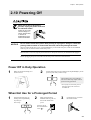
2-10 Powering Off
When not in use for prolonged
periods, unplug the power cord from
the electrical outlet.
Failure to do so may
result in danger of
shock, electrocution,
or fire due to
deterioration of the
electrical insulation.
NOTICE
Do not switch off the main power while printing is in progress. Doing so causes the
printing head to remain in contact with the sheet, which may damage the head.
When switching off the main power, use the [POWER] key to turn off the sub power, make sure the POWER
LED has gone out, and then switch off the main power.
When the unit is not in use, keep the pinch rollers raised. The pinch rollers may be deformed if left engaged.
Before unplugging the power cord, make sure the main power switch have been turned off.
Power Off in Daily Operation
1
2
Make sure the sheet loading lever
has been raised.
Switch off the sub power by holding down the [POWER] key on the
operation panel until you hear a beep.
The machine goes to sleep when the
time set for auto-sleep elapses with no
operation being performed.
* In everyday use, the main power is
normally always left on and not
switched off.
When Not Use for a Prolonged Period
1
Switch off the sub power by
holding down the [POWER]
key until you
hear a beep.
2
Make sure the flashing
POWER LED has gone out,
then switch off the main
power.
3
Unplug the power cord from
the electrical outlet.
Press the side of
the switch marked
with “
”.
37
Chapter 2 - Basic Operation
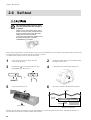
When Not in Use
Place the included dust cover over the
machine.
This prevents dust from accumulating on
the machine and the material.
Storing Material
When storing material, place it in plastic bags to protect it
from dust and grime.
Also, do not store material on its side; store is vertically (standing up).
If material is placed on its side without wrapping it in plastic, dust and grime may build up on the surface of the material and damage the
printing heads when printing.
Not OK
38
OK
Chapter 3 - User's Reference
Chapter 3 - User's Reference
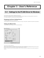
3-1 Settings for the PC-600 Driver for Windows
This sends data to the PC-600 from a Windows-based program.
When you are sending data from a commercial draw-type program, make the settings for the cutting parameters with the driver.
For a detailed explanation, see the help screens for the PC-600 driver.
Displaying the Driver Setting Screen
To make the settings for the driver, open Properties.
To open Properties, use the printing menu for the program you're using to set the printer to [Roland PC-600], then click [Properties].
Setting the Material Size
At the [Size] tab, make the setting for the size of the loaded material.
Choose the size of the loaded media.
When you choose the media size with [Sheet Size], the [User Size] values for [Width] and [Length] show the size values. Also, the
[PlotArea] value for the size (the media size area minus margins) appears to the right.
If there is no selection for the size of the loaded media, choose "User Size," then at [User Size], type in the width and length of the
material.
39
Chapter 3 - User's Reference
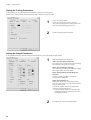
Setting the Cutting Parameters
At the [Cutting] tab, select the cutting line and make the setting for the cutting speed.
Bitmap data is printed, without performing cutting. Make cutting lines using vector data.
1
Choose the cutting method.
Specify the cutting line by color or line type.
Also, choosing [All] performs cutting for all vector
data, and choosing [None] prints all data.
2
Set the movement speed for the blade.
Setting the Output Parameters
At the [Output Option] tab, make the settings for the ink ribbons you're using and the printing method.
1
Make the settings for the output data.
When only [Printing] is selected
Only printing data is output. Data set for the cutting
lines with the [Cutting] tab is not output.
When only [Cutting] is selected
Only data set for the cutting lines with the [Cutting]
tab is output. Other data is not output.
When both [Printing] and [Cutting] are
selected
All data is output, regardless of whether it is
printing data or cutting data.
When [FormFeed] is on
When [Form Feed] is on, a feed operation takes
place and a new origin point is set after the medium
has been printed or cut.
The amount of feed is equal to the length of the
printing area for the material size.
* You can make the setting for [Cut Media After
Printing]on the [Driver Options] tab only when
[FormFeed] is selected.
2
40
From [Process], choose the printing method.
Chapter 3 - User's Reference
3
To use a special color, choose the color to use from
[Special], then associate the image color (the color
you specified using the program) with an ink ribbon.
Install an ink-ribbon cartridge of the color you chose
in the PC-600.
To print using only special colors, clear the selection
for the [Process] item.
4
Choose the type of cartridge.
5
To print a photographic image, select [PhotoColor].
To print a poster image or drawing, select
[SpotColor].
If the substrate is visible due to variations in printing
alignment for each ribbon, select [Trapping].
Correcting an Image
When performing output, this corrects and outputs the original image.
If necessary, make the setting at the [Image Correction] tab.
41
Chapter 3 - User's Reference
Setting the Operating Parameters
At the [Driver Options] tab, make the settings for the machine's operating parameters for other than printing and cutting.
42
1
To use the settings on the PC-600 and not use the
driver settings, choose [Enable Machine Settings].
2
To use the driver settings, choose [Enable Driver
Settings] and make the settings for each item.
For items with check boxes, select the check box
(putting a " " in the check box) to make the setting
for [Enable].
Chapter 3 - User's Reference
3-2 Settings (Making Settings on the PC-600)
You can make the settings for the following item on the PC-600 itself. Make these settings as required.
Auto sheet cut
: When this is enabled, the material is separated from the roll when a material-cutting command is sent.
Auto-sleep
: This sets the interval after which the PC-600 goes to sleep when there is no operation of data processing. When the
machine goes to sleep, it enters the power-saving mode. The POWER LED flashes at this time.
To cancel the sleep state, send some data or press any key on the operation panel.
Front edge sense : This detects the front edge of the material. Setting this to [ENABLE] adds detection to the setup operations.
Because printing or cutting starts only after detecting the edge of the material, is detected, the amount of wasted
material can be reduced.
Blade offset
: This sets the amount of offset for the tip of the blade. The amount of blade offset is the length from the centerline of
the blade to the blade tip.
The amount of offset varies according to the blade.
Crop marks
: This prints crop marks on the material.
This is handy when you want to remove a piece of material after printing, laminate it, then load it again to perform
cutting.
* You can also make the setting for printing crop marks using the PC-600 driver. If the setting for enabling or
disabling crop marks has been made using the driver, the driver setting determines whether crop marks are printed.
If you're using Roland COLORCHOICE®, make the settings on the PC-600. The settings for this item cannot be
made on Roland COLORCHOICE®.
Prefeed mode
: This feeds the material forward and backward before printing or cutting.
This lets you make sure ahead of time that the material can be fed correctly during printing or cutting. It also makes
material feed more stable by placing grit-roller tracks on the material in advance.
Beep (warning sound for the ink-ribbon cartridges)
: This switches the warning bell for the ink-ribbon cartridges on or off.
* You can also make the setting for turning the warning beep on or off using the PC-600 driver. When the setting has
been made using the driver, the driver setting determines whether the warning beep is on or off.
If you're using Roland COLORCHOICE®, make the settings on the PC-600. The settings for this item cannot be
made on Roland COLORCHOICE®.
Ribbon Saver
: When empty data for 70 mm (2-13/16 in.) or more in the direction of carriage movement is sent, the portion is output
without winding the ink ribbons, making the most economical use of the ink ribbons.
When this is on, images with junctions between bands that are slightly visible may be printed. If image quality is a
priority, switch this off.
* You can also screwdriver for turning Ribbon Saver on or off using the PC-600 driver. When the setting has been
made using the driver, the driver setting determines whether Ribbon Saver is on or off.
If you're using Roland COLORCHOICE®, make the settings on the PC-600. The settings for this item cannot be
made on Roland COLORCHOICE®.
43
Chapter 3 - User's Reference
Making the Settings
1) Hold down the [ALIGN POINT] key on the panel while you turn the [POWER] key (sub power) on. The ALIGN POINT LED and
the POWER LED lights up.
and
keys changes the displayed CARTRIDGE HOLDER LEDs.
2) Pressing the
3) Referring to the table below, use the and keys to illuminate or extinguish the CARTRIDGE HOLDER LEDs for the value you
want to set.
4) The setting is completed when the [POWER] key is used to switch off the sub power.
The setting that has been made is stored in memory even after the power is switched off. To change the setting, simply repeat the
procedure just described.
You can perform an operation check to check the present settings with the printing results. For more information about the operation
check, see "2-6 Self-test."
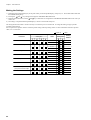
: Lights up
CARTRIDGE HOLDER LED
Functions
Auto sheet cut
Setting item
: Dark
CARTRIDGE HOLDER LED
Value
Enable
Setting state
Factory
Default
√
Disable
Auto-sleep
30 min.
√
60 min.
Disable
Front edge sense
Disable
Blade offset
0.25 mm
√
Enable
√
0.50 mm
Crop marks
Disable
√
Enable
Prefeed mode
Enable
√
Disable
Beep
Enable
(warning sound for the ink-ribbon cartridges)
Disable
Ribbon Saver
Enable
Disable
44
√
√
Chapter 3 - User's Reference
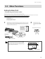
3-3 Other Functions
Setting the Base Point
– Printing/Cutting at the Desired Location –
The BASE POINT key is used to set the base point for printing or cutting.
The base point can be set anywhere you like on the material, making it possible to print or cut unused portions of the material.
The base point can be set after finishing material setup (and lowering the sheet loading lever).
The base point remains enabled until you perform one of the operations described below.
- Raising the sheet loading lever
- Feeding the page
- Resetting the base point
- Pressing the [DATA CLEAR] key
- Pressing the [SHEET CUT] key
1
Open the front cover and use the cursor keys to move the carriage to a new base
point for printing or cutting. The BASE POINT setting can be only when in the
printing or cutting area. Take care to ensure that the front edge of the sheet does
not come loose from the front sensor.
2
The center of the
blade mounted
on the cutting
carriage is set as
the origin point.
With the front cover left
open, hold down the [BASE
POINT] key until you hear a
beep.
The BASE POINT LED lights up
< Example >
NEW BASE POINT
If the base point has been moved, enter the value for W
in the figure at right as the sheet size width for the driver.
If this value is not corrected, output results may be cut off
before reaching their normal end.
Rear
Front
H
W
Enter this value
NEW BASE POINT
45
Chapter 3 - User's Reference
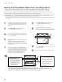
Setting the Crop Marks, Base Point, and Align Point
– Remove the Printed Material, then Reload the Material and Perform Cutting –
This feature is for performing position alignment in cases where printing is performed, after which the material removed from the
machine for further processing (such as laminating), then again loaded on the machine for cutting.
* Setting crop marks to [ENABLE] changes the printing/cutting area. For more information, see "3-5 About the Printing/Cutting Area."
* When reloading a portion that has already been printed and cut off of the roll, them make sure there is at least 90 mm (3-9/16 in.)
from where printing ended to the rear edge of the material (where it was cut from the roll).
When the material is to be cut off automatically, then at the PC-600 driver [Driver Options] tab, set [Page Spacing] to 90 mm (3-9/16
in.) or more.
1
3
Hold down the [ALIGN POINT] key on the panel
while you turn the [POWER] key (sub power) on.
The ALIGN POINT LED and the POWER LED
lights up.
Use the and keys to make the LED for
CARTRIDGE HOLDER 5 light up.
4
The setting is completed when the [POWER] key is
used to switch off the sub power. Crop marks are
now set to [ENABLE].
5
Press the [POWER] key (sub power) to switch on
the power.
You can also enable or disable crop marks by
making the setting using the driver. When you are
making the setting with the driver, steps 1 through 5
are not necessary.
7
When printing finishes, raise the sheet loading
levers, remove the material, and perform lamination
(or whatever further processing needs to be done).
When done, reload the material in about the same
position used for printing and lower the sheet
loading levers. (The SETUP LED lights up.)
10
2
Use the
and
keys to make the LEDs for
CARTRIDGE HOLDER 1 and 3 light up.
6
Send the printing data from the computer.
Three crop marks are automatically printed on the
left and right areas at the front edge of the material.
Rear
Front
Crop marks
8
Use the
and
keys to move the carriage to the
center of the platen.
9
Install the alignment tool on the cutting carriage.
Rear
1) Set the base point
Use the arrow keys to move
the tip of the alignment tool
to the square crop mark at
the lower right area of the
material, then press the
[BASE POINT] key.
Front
2) Set the align point
Use the arrow keys to move
the tip of the alignment tool
to the crop-mark corner in
the length direction of the
material (at either the lower
left or upper right).
Then press the [ALIGN
POINT] key.
• The align point cannot be set to both the lower left and upper right points.
• The align point cannot be set if the angle between the base point and the align point is 5 degrees or more.
• Marks set with the application software (such as crop marks) cannot be used.
46
Chapter 3 - User's Reference
11
Remove the alignment tool from the cutting carriage
and install the blade holder.
12
Send the cutting data from the computer.
3-4 Tips and Tricks for Printing/Cutting
Removing the Blank Space Surrounding a Picture
Cutting outline
Material
Stick
Adding Color to a Border
Cutting outline
Stick
Material
47
Chapter 3 - User's Reference
Correcting Line Pitch
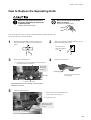
How to Correct Line Pitch
1) Hold down the [BASE POINT] key on the panel while you turn the [POWER] key
(sub power) on. The BASE POINT LED and the POWER LED lights up.
2) Pressing the
and
keys changes the displayed CARTRIDGE HOLDER LEDs.
Line pitch: Correct
3) Referring to the table below, use the
offset between lines.
and
keys to determine the amount of
4) The setting is completed when the [POWER] key is used to switch off the sub power.
The setting that has been made is stored in memory even after the power is switched off.
To change the setting, simply repeat the procedure just described.
* Distance accuracy cannot be guaranteed when line-pitch correction has been performed.
Line pitch is too wide, and spaces
appear between lines.
1 step = approx. 0.1 dot
Pitch
(Step)
CARTRIDGE HOLDER LED
Pitch
(Step)
-1
Default (no offset)
-2
+1
-3
+2
-4
+3
-5
+4
-6
+5
-7
+6
-8
+7
-9
+8
-10
+9
-11
+10
-12
+11
-13
+12
-14
+13
-15
+14
-16
+15
-17
+16
-18
+17
-19
+18
-20
+19
-21
+20
-22
+21
-23
+22
-24
+23
-25
+24
-26
+25
-27
+26
-28
+27
-29
+28
-30
+29
+30
48
: Flashing
: Dark
CARTRIDGE HOLDER LED
Chapter 3 - User's Reference
3-5 About the Printing/Cutting Area
..... Printing/Cutting area
..... Crop mark
Factory default
When front edge sense is enabled
55 mm (2-3/16 in.)
55 mm (2-3/16 in.)
Pinch roller (left)
Pinch roller (left)
16 mm
68 mm
(11/16 in.) (2-11/16 in.)
or more
12 mm
(1/2 in.)
16 mm
(11/16 in.)
68 mm
(2-11/16 in.)
Pinch roller (right)
Pinch roller (right)
When crop marks is enabled
When crop marks are enabled
and a base point has been set
55 mm (2-3/16 in.)
Pinch roller (left)
16 mm
(11/16 in.)
12 mm
(1/2 in.)
55 mm (2-3/16 in.)
Pinch roller (left)
68 mm
(2-11/16 in.)
12 mm
(1/2 in.)
Pinch roller (right)
16 mm
(11/16 in.)
68 mm
(2-11/16 in.)
12 mm
(1/2 in.)
Pinch roller (right)
49
Chapter 3 - User's Reference
3-6 About the Blade
If the Blade Becomes Dull
When the blade starts to lose its sharpness, try gradually increasing the cutter force.
Increasing the cutter force temporarily allows the blade to perform better. However, once the blade is dull, it is time to replace it.
Average Blade Life
The life of a blade varies, depending on the amount of cutting it performs.
The total cutting length can vary considerably, depending on the thickness, toughness, and type of adhesive of the cut material. Set an
appropriate cutter force, one that is well matched to the material and the hardness of the blade. This will extend the life of the blade.
Excessive cutter forces can cause the blade to wear out quickly. Care should be taken.
The table below provides a rough guide to appropriate cutting conditions and expected blade life.
Please note that making the settings for conditions shown below will not necessarily achieve attractive cutting results in all circumstances. Before performing actual cutting, please carry out a cutting test and adjust as required (see "6 Cut Test & Self-test").
50
Blade
Material
ZEC-U1005
ZEC-U5025
Pen-force scale
Speed
Blade compensation
Life of a blade
General Signal Vinyl
30 cm/sec.
(11.811 in./sec.)
0.25 mm
(0.00984 in.)
8000 m
(314960 in.)
General Signal Vinyl
30 cm/sec.
(11.811 in./sec.)
0.25 mm
(0.00984 in.)
4000 m
(157480 in.)
Chapter 3 - User's Reference
How to Replace the Separating Knife
Make sure the power to the unit is
off before attempting to replace the
separating knife.
Do not touch the tip of the blade
with your fingers.
Doing so may result in injury.
Doing so may result in injury.
If the separating knife, replace it with the replacement blade included with the PC-600.
Follow the steps below to replace the blade.
1
2
Hold down the [POWER] key on the control panel
until the LED starts to flash, and switch off the sub
power.
Make sure the flashing POWER LED has gone out,
then switch off the main power.
Press the side of
the switch marked
”.
with “
3
4
Remove the separating knife.
Replace with a new knife.
2) Grasp the top portion of the holder, and slowly pull it
out in the direction of the arrow.
Do not pull
back while
doing this.
Positioning groove
Holder
The knife is secured in place
by the magnet.
1) Remove the screw.
* If the blade remains in the carriage, use the included
tweezers to remove it.
5
Install the separating knife.
1) Grasp the top portion of the holder and
slowly insert it into the groove.
2) Tighten the screw.
Take care to ensure
that the knife does
not slip.
51
Chapter 3 - User's Reference
3-7 Care and Maintenance
Do not touch the area around the
printing carriage with the hands.
Failure to do so may result in burns.
NOTICE
Be sure to switch off the main power for the PC-600 before attempting to clean the unit and platen or using
head cleaner to clean the printing head.
Never attempt to oil or lubricate the mechanism.
Cleaning the Printing Head
The PC-600 automatically performs cleaning of the printing head.
You can also perform forced cleaning by pressing the [HEAD CLEANING] key, but normally automatic cleaning is sufficient. If printing
is especially grimy, press the [HEAD CLEANING] key to perform cleaning. To start cleaning, hold down the key until a beep is heard.
The head is cleaned with the cleaning pad on the front-left surface of the unit when an ink-ribbon cartridge is replaced. Ordinary grime is
removed by this automatic cleaning, but when soiling is severe, the head cleaner included with the unit should be used to remove it.
The method described below is used to perform cleaning with the head cleaner.
NOTICE
Drops of cleaning fluid may spray out when the cap is opened. Hold away from the platen when opening the
cap. The platen may be discolored by any cleaning fluid that comes in contact with it. (The cleaning fluid is
non-toxic.)
Use the included head cleaner to
remove grime from the edges of the
printing heads.
Edges of the printing heads
Separation lever
Be careful not to let any head
cleaner touch the separation lever.
Bottom surface of
the printing head
Head cleaner
If this cleaning fails to remove all grime, then use the included head-cleaning sheet to perform cleaning.
52
Chapter 3 - User's Reference
How to Use the Cleaning Sheet
The following details the correct usage of this cleaning sheet.
Failure to observe the following points may result in damage to the machine.
• Do not use any cleaning sheet that has a damaged surface such as cuts, tears or creases.
• The printing head can be damaged by dust.
• The Pinch rollers should be set over the black bands at either end of the sheet, to ensure that the head is restricted to the center cleaning
area of the sheet and cannot pass over marks left by the pinch rollers.
• Store the cleaning sheet in a clean place and wipe the cleaning surface with a "lint free" cloth before use.
1
3
Switch off the sub power.
2
Open the front cover.
4
Take out the ink-ribbon cartridge.
Raise the sheet loading
lever.
Ink-ribbon cartridge
5
Remove the blade holder.
Blade holder
6
Keep pushing the [HEAD CLEANING] Key, and
the sub power on.
Cutting carridge
+
7
Load the cleaning sheet.
Position the material, the pinch rollers, and the grit rollers at the locations shown below.
Load so that the pinch rollers descend on the black blacks on the left and right edges of the cleaning sheet.
Matt face is up side
2nd grit roller
from the right
Rightmost grit roller
Pinch roller (left)
Make sure the material lies
over the front and rear sensors.
Pinch roller (right)
53
Chapter 3 - User's Reference
8
Lower the sheet loading lever.
If the material is not loaded at the correct location,
the SETUP LED flashs at the same time.
If this happens, reload the material at the proper
location.
9
When the front cover is closed, the BUSY LED
flashes and head cleaning starts.
Head cleaning is finished when the BUSY LED
goes dark.
10
When cleaning is finished, open the front cover and
raise the sheet loading lever.
11
Remove the material.
12
Switch off the sub power.
Cleaning the Main Unit
For routine cleaning, use a soft piece of cloth.
Cleaning the Platen
If the platen becomes soiled, wipe it clean with a dry, soft cloth.
Do not wipe with a head cleaner or alcohol.
Use care when cleaning to avoid damaging the surface of the platen. Printing quality may suffer.
If printing on the platen was performed by mistake
If the grime is allowed to remain, printing may be smudged or uneven. Follow the steps below to clean.
1) Apply cellophane tape over the soiling, then rub the tape with your finger.
2) Slowly peel off the tape.
Repeat until the grime is removed.
54
Chapter 3 - User's Reference
Cleaning the Cleaning Pad
If the cleaning pad becomes dirty, clean it gently using a commercially available brush (item with soft fibers) or the like.
The Cleaning Pad
If the cleaning pad on the left edge of the unit's front surface is damaged, the printing head may be destroyed.
If the cleaning pad is damaged by a blade or the like, replace it with a new cleaning pad.
Continuing to use a cleaning pad that has deteriorated may impair printing quality.
As a general guideline, the cleaning pad should be replaced with a new one after printing 50 m (1960 in.) of material (24 in. in width).
Replacing the Cleaning Pad
NOTICE
When printing, be sure a cleaning pad is installed. Performing printing with no cleaning pad installed may
destroy the printing head.
Continuing to use a cleaning pad that has deteriorated may impair printing quality.
As a general guideline, the cleaning pad should be replaced with a new one after printing about 50 m of material (24" in width).
Also, if the cleaning pad becomes damaged, replace it immediately.
Failure to replace it may cause destruction of the printing head.
Follow the steps below to replace the cleaning pad.
1
Remove the old cleaning pad.
2
Install the new cleaning pad.
Peel off slowly from the right-hand corner.
Cleaning pad
3
Check the following:
- Make sure the cleaning pad has not come loose.
- Make sure there is no gap between the cleaning
pad and the platen stopper.
While orienting as shown
in the figure and holding
all the way to the left,
press into place.
Platen stopper
Cleaning the Reflective Panel
If the reflective panel becomes dirty, clean it by moistening a cloth with water, wringing well, and wiping gently.
55
Chapter 3 - User's Reference
3-8 What to Do If...
NOTICE
If you want to completely stop the operation of the PC-600, press the [POWER] key.
If the sub power cannot be switched off, then switch off the main power. In such cases, however, the printing
head remains in contact with the sheet, and attempting to pull out the sheet or move the carriage while in this
state which may damage the head.
If the PC-600 doesn't run...
Connection cable
PC-600
Are the computer and the PC-600 linked with the
right cable?
Check the operating temperature in "3-9 Specifications" and
use the machine in an appropriate environment.
The type of cable you need is determined by your computer
and the software you are using. Even if the computer is the
same, running different software may require a different
cable. Use the cable specified in your software.
Is the PC-600 sub power on?
Is the cable making a secure connection?
Turn on the sub power (See “2-2 Powering On” ) .
Connect securely (See “Set-up and Connections” ) .
Is the sheet loading lever not in the lowered
position?
Software
Is the machine being used at the proper operating
temperature?
If the sheet loading lever has not been lowered, load the
material correctly and lower the sheet loading lever.
Has the correct driver selection been made for the
application software?
Select the appropriate PC-600 driver.
Has the front cover not been closed?
Close the front cover. Operation is paused while the front
cover is open. The FRONT COVER LED flashes while the
front cover is open.
Are the settings for the driver software correct?
Make the correct settings for the output port and communication parameters (see "Installing the DRIVER").
Has the ribbon been used up?
Replace with a new ribbon cartridge (see “2-5 Installing a
Ribbon Cartridge Replacing an Ink Cartridge”) .
Has the machine gone to sleep?
When the user settings on the PC-600 have been used to set
auto-sleep to [30 min.] or [60 min.], then when the set time
elapses after printing or cutting operation, panel operation, and
data transmission from the computer stop, the PC-600 goes to
sleep.
To cancel the sleep mode, send data from the computer or
press any key on the operation panel.
56
The SETUP LED and CARTRIDGE
HOLDER LEDs are flashing
The machine may be malfunctioning.
The SETUP LED and CARTRIDGE HOLDER LEDs flash
when a fatal error occurs. When this happens, all operation
except for switching off the main power becomes impossible.
Switch off the main power, then switch it on again.
If this does not correct the problem, then check the flashing
LEDs and contact your authorized Roland DG Corp. dealer or
service center.
Chapter 3 - User's Reference
Clean, attractive printing is impossible
Is the printing head dirty?
Clean the printing head (see “ 3-7 Care and Maintenance”).
If cleaning will not improve the printing quality, the printing
head might reach to the end of its life.
Contact your authorized Roland DG Corp. dealer or service
center for replacement of the printing head.
Is the surface of the platen dirty or scratched?
Has the material been sufficiently acclimated
before use?
The material may shrink or expand due to absorption of
moisture in the air. If such shrinking or expansion occurs
during printing, the printed pattern may be misaligned.
Pull out the amount of roll material to be used, and allow to
stand for 30 minutes to an hour.
The amount of time required for acclimation varies according
to the type of material.
Clean the platen (see “ 3-7 Care and Maintenance”).
Has a used-up ink ribbon been flipped over or
rewound and reused?
Is the cleaning pad free of dust or damage?
A used ribbon cartridge cannot be reused.
Do not attempt to turn over and reinstall a used ribbon
cartridge, or to rewind the ink ribbon and reuse the cartridge.
A dusty or damaged cleaning pad may destroy the printing
head. Gently wipe away any adhering dust or grime.
Also, if the cleaning pad becomes damaged, replace it
immediately.
Has the cleaning pad deteriorated?
Continuing to use a cleaning pad that has deteriorated may
impair printing quality.
As a general guideline, the cleaning pad should be replaced
with a new one after printing about 50 m of material (24 in. in
width).
Is the material free of soi-ling? (Is the material free
of printing grime, dust, or damage?)
If the surface of the material is dusty or damaged, or if it has
been touched by the hands, leaving perspiration or oils,
printing may suffer drop-out or smudging, and fail to yield
attractive results.
If the material is dirty, then before you load it on the machine,
clean it using rubbing alcohol.
When loading material after cleaning, be careful not to let the
printing area get dirty.
Also, if the material is dusty or damaged, not only may
attractive printing be impossible, but the printing heads may
be damaged as well. If the material is damaged, replace it with
a new piece of material.
When storing material, be careful to protect it from dust or
damage.
Have the ribbon cartridges been installed correctly?
Correctly load the cartridge in the cartridge holder. Ribbon
looseness or slack in the ribbon can also have a negative effect
on attractive printing. (See “2-5 Installing a Ribbon
Cartridge”. )
A cartridge change error occurs
Have the ribbon cartridges been installed correctly?
Correctly install the ribbon cartridges. (See “2-5 Installing a
Ribbon Cartridge”. )
Is the reflective panel free of soiling?
If the reflective panel is soiled, it may become impossible to
change the ink-ribbon cartridge correctly.
If dirty, then use a cloth moistened with water then wrung
well, and wipe gently to clean.
57
Chapter 3 - User's Reference
Cartridge detection is incorrect
Has a marker seal on a ribbon cartridge become
dirty?
Wipe off any grime on marker seals.
Are ribbon cartridges designed exclusively for the
PC-600 being used?
Use only exclusive PC-600 ribbon cartridges.
Printing or cutting stops before
the normal end is reached
Has the material been displaced from the sensors
at the front or rear?
If the material becomes separated from the front or rear sensor
during printing or cutting, operation stops. Be sure to use
material of adequate size for the current printing or cutting job
(See “About the Printing/Cutting Area” ) .
Has a ribbon cartridge run out of ribbon?
If there is no more ink ribbon left for printing, replace the
ribbon cartridge with a new one (See “2-5 Installing a Ribbon
Cartridge Replacing an Ink Cartridge” ) .
Full-color printing is impossible
Is the full set of four-color ribbon cartridges
(CMYK) installed?
Full-color printing cannot be performed unless all four colors
(CMYK) are available. Load the ribbon cartridges for cyan,
magenta, yellow, and black in the cartridge holders. (See “2-5
Installing a Ribbon Cartridge”. )
Have the correct settings been made for the
software driver?
Specify Process Color at the driver setup screen. (Please refer
to the help file for the PC-600 DRIVER. )
Does the computer have enough memory?
If the computer runs out of memory during operations, try
closing other open applications or restarting Windows®.
If you still get a message about insufficient memory, check
how much free space is left on your hard drive. Windows®
normally uses a portion of the hard drive as virtual memory,
and so an error message may appear if the hard drive runs out
of free space. If this happens, delete unneeded files or move
them to a different drive to free up more space.
If you've followed the steps above and still get an error
message about insufficient memory, installing more RAM in
your computer is recommended.
58
The material slips away from the
pinch rollers during operation
Is the loaded material straight, and not at an
angle?
If the loaded material is crooked, it may come loose from the
pinch rollers during feed operations. Make sure the material is
straight by aligning it with the guideline stickers when loading
(See “2-3 Loading the Material”. )
Is lengthy printing or cutting (1 m (39-3/8 in.) or
more) being performed?
The material can be made less likely to come loose by moving
the pinch rollers inward by a small amount. Also, make the
user setting on the PC-600 to enable the prefeed function, or,
alternatively, use key operations after loading the material to
feed the material by the amount to be used to make sure the
material will not come loose from the pinch rollers, and then
perform the actual printing or cutting. (See “2-3 Loading the
Material To Perform Long Printing/Cutting”. )
During operation, do the left and right edges of the
material touch the inner surfaces of the PC-600?
Make sure that the left and right edges of the material do not
touch the inner surfaces of the PC-600 during operation. Such
contact may damage the material, and could also make it
impossible to advance the material–thus causing it to slip.
Is roll material being used?
When you are using roll material, make the user setting on the
PC-600 to enable the prefeed function. If the prefeed function
has been disabled, pull out from the roll the amount to be
used, and then carry out printing or cutting. Slippage of the
material may occur if the PC-600 has to pull out the material
wound on the roll as is performs printing or cutting.
Chapter 3 - User's Reference
Is the brake installed?
If the included brake is not attached, then install it (see "2-3
Loading the Material").
If the settings on the machine have been made to set the
prefeed function to [ENABLE], then before performing
printing or cutting, the length of material required for output is
automatically pulled out from the roll, then returned to the
rear, where it is left slack. The brake keeps the material from
returning to the roll at this time.
If the material is not pulled out from the roll first, printing or
cutting may be misaligned, or the material may come loose or
jam.
Printing on the platen was
performed by mistake
Clean the platen. (See "3-7 Care and Maintenance.")
When performing long printing,
the colors are misaligned
When performing long printing or
cutting, operation stopped before
printing or cutting finished
Depending on the program you're using, it may be possible to
print or cut only up to the program's maximum output size.
One portion cannot be printed or
cut
Do the settings for material size (printing area) for
the driver and the program match each other?
If the settings for material size (printing area) for the driver
and the program are different from each other, the output
location may be shifted.
Be sure to make sure the settings for material size (printing
area) for the driver and the program match each other before
performing output.
This is caused by expansion and contraction of the material.
For roll material in particular, the time required for the
material to uncurl and acclimatize to the ambient temperature
and humidity is different for the outer portions and the central
portion of the roll.
Before you perform long printing, pull out the length of
material to be printed from the roll and let it allow to stand for
about 30 minutes to an hour to allow it to become acclimatized
to the environment.
59
Chapter 3 - User's Reference
When performing continuous
printing, the image quality
changes or margins are grimy
When you perform continuous printing, image quality may
deteriorate, or ink may build up in the margins. This is because
the printing heads grow hot and apply more heat than
necessary to the ink ribbon.
This is especially likely to occur when performing full-color
printing of an image with a large printing surface area, or
when printing an iron-on decal.
If image quality changes when performing continuous
printing, open the front cover to pause printing. Let stand for
about 15 minutes, then close the front cover to resume
printing. This allows the printing heads to return to close to
normal temperature and print with normal image quality.
When printing solid-color areas,
there are gaps between lines
Differences in material thickness may cause slippage in the
amount of feed by the grit rollers.
If you want to eliminate gaps between lines, then correct the
line pitch. (See "3-4 Tips and Tricks for Printing/Cutting
Correcting Line Pitch.")
Printing and cutting are
misaligned
When printing is followed by cutting, expansion or contraction
of the material during printing may cause the cutting line may
be displaced from the printing location.
Take steps to make the displacement less conspicuous, such as
by creating a margin around the printed portion or adding a
thick border. (See "3-4 Tips and Tricks for Printing/Cutting.")
60
The Material is not cut properly
Are the blade and blade holder installed correctly
and securely?
Install these so that there is no looseness (see “2-1 Installing a
Blade”).
Is the blade chipped?
If it is, replace it with a new one (see “2-1 Installing a
Blade”).
Check if there are any dirty deposits on the blade.
If dirty, remove and clean the blade.
Make sure you are using an appropriate cutter
force setting.
Perform a “cutting test,” then adjust the tool force slider as
necessary to obtain the optimum cutter force (see “2-4 Cut
Test”).
Reducing the margin at the front
edge of the material
* Only If You're Using Roll Material *
Use the user settings on the PC-600 to enable front-edge
sensing. When this setting is made, the machine rolls back the
margin at the front edge of the material before performing
printing or cutting.
Operation stops while continuous
printing is in progress
If the printing heads grow hot during continuous printing,
operation stops automatically to allow the heads to cool. When
cooling ends, operation resumes.
Chapter 3 - User's Reference
3-9 Specifications
PC-600
Mechanism
Media-movement method, Thermal-transfer serial, Automatic cartridge-changing type
Acceptable Media Width
50 to 610 mm (2 to 24 in.)
Maximum Work Area
571.6 mm x 24,998 mm (22-1/2 in. x 984-1/8 in.) * This may be restricted by the program
Acceptable Media Type
Adhesive vinyl, thickness 0.23 to 0.06 mm (0.00906 to 0.00237 in.)
Tools
Cutter: blade & blade holder.
Printing ribbon: thermal transfer ribbon cartridge.
Number of installed cartridges
6 pieces
Cutter Force
30 to 200 gf
Cutting Speed
10 to 300 mm/sec. (0.393 to 11.811 in./sec)
Printing Speed
Max.252 mm/sec. (9.921 in./sec)
Cutting Resolution (Software Resolution)
0.025 mm/step (0.000984 in./step)
Printing Resolution
600 dpi x 600 dpi, 1,200 dpi (carriage-movement direction) x 600 dpi
Cutting Accuracy (Distance Accuracy)
Less than ±0.3 % of distance traveled or ±0.3 mm (±0.0118 in.), whichever is greater
Registration Between Printing & Cutting
Less than ±0.3 mm (±0.0118 in.)
(Excluding expansion or contraction of the media, and
excluding times when material is been reloaded)
Interface
Bidirectional parallel interface (compliant with IEEE 1284 : nibble mode)
Memory
2 Mbyte
Control Switches
POWER, DATA CLEAR, BASE POINT, ALIGN POINT, CUT TEST, SHEET CUT,
HEAD CLEANING, TOOL FORCE,
LED
,
,
,
POWER, BASE POINT, ALIGN POINT, DATA CLEAR, CARTRIDGE HOLDER 1—6,
SETUP, BUSY, FRONT COVER
Power-saving function
Auto-sleep
Power consumption
Printing / Cutting mode Maximum : 1.2 A / 100V–240V ±10% 50/60 Hz
Acoustic noise level
Printing/Cutting mode: less than 65 dB (A)
Standby mode Maximum : 0.3 A /100V–240V ±10% 50/60 Hz
Standby mode: less than 40 dB (A)
(According to ISO7779)
Dimensions
Main unit
1125 mm (W) x 326 mm (D) x 285 mm (H) (44-5/16 in. (W) x 12-7/8 in. (D) x 11-1/4 in. (H))
When cover is opening:
1125 mm (W) x 326 mm (D) x 377 mm (H) (44-5/16 in. (W) x 12-7/8 in. (D) x 14-7/8 in. (H))
With stand
1125 mm (W) x 756 mm (D) x 1134 mm (H) (44-5/16 in. (W) x 29-13/16 in. (D) x 44-11/16 in. (H))
When cover is opening:
1125 mm (W) x 756 mm (D) x 1226 mm (H) (44-5/16 in. (W) x 29-13/16 in. (D) x 48-5/16 in. (H))
Weight
Main unit
28 kg ( 61.7 lb.)
With stand
47 kg ( 103.6 lb.)
Operating Temperature
15 to 30°C (59 to 86°F)
Operating Humidity
35 to 70% (non-condensing)
Accessories
Power Cord, thermal transfer ribbon cartridge (resin), blade (carbide),
blade holder (blade holder and pin), material for test cuts, head cleaner, alignment tool, brake,
replacement blade for separating knife, cleaning sheet, cleaning pad, dust cover, PC-600 DRIVER
for Windows® 98/95, Roland COLORCHOICE® CD-ROM, user’s manual (this manual),
notes on usage, quick reference guide, Roland COLORCHOICE® installation guide
61
Chapter 3 - User's Reference
Interface specifications
Parallel
Standard
Bidirectional parallel interface (compliant with IEEE 1284: nibble mode)
Input signals
STROBE (1BIT), DATA (8BITS), SLCT IN, AUTO FEED, INIT
Output signals
BUSY (1BIT), ACK (1BIT), FAULT, SLCT, PERROR
Level of input output signals
TTL level
Transmission method
Asynchronous
Interface connector
Parallel interface connector
(in compliance with specifications of Centronics)
Signal
number
Terminal
number
Signal
number
SLCT IN
36
18
HIGH***
HIGH*
35
17
GND
NC
34
16
GND
GND
33
15
NC
FAULT
32
14
AUTO FEED
INIT
31
13
SLCT
30
12
PERROR
29
11
BUSY
28
10
ACK
27
9
D7
26
8
D6
25
7
D5
24
6
D4
23
5
D3
22
4
D2
21
3
D1
20
2
D0
19
1
STROBE
GND
Pin Connection
62
18
1
36
19
Please read this agreement carefully before opening the sealed
package or the sealed disk package
Opening the sealed package or sealed disk package implies your acceptance of the terms and conditions of this agreement.
If you do NOT accept this agreement, retain the package UNOPENED. (This product is just one of included items. Please
be aware that any amount of the purchase price will not be refunded for return of this product as a single item, regardless
of whether the package is opened or unopened.) The enclosed Roland product is a single user version.
Roland License Agreement
Roland DG Corporation ("Roland") grants you a non-assignable and non-exclusive right to use the COMPUTER
PROGRAMS in this package ("Software") under this agreement with the following terms and conditions.
1. Coming into Force
This agreement comes into force when you purchase and open the sealed package
or sealed disk package.
The effective date of this agreement is the date when you open the sealed package
or sealed disk package.
2. Property
Copyright and property of this Software, logo, name, manual and all literature
for this Software belong to Roland and its licenser.
The followings are prohibited :
(1) Unauthorized copying the Software or any of its support file, program module
or literature.
(2) Reverse engineering, disassembling, decompiling or any other attempt to
discover the source code of the Software.
3. Bounds of License
Roland does not grant you to sub-license, rent, assign or transfer the right granted
under this agreement nor the Software itself (including the accompanying items)
to any third party.
You may not provide use of the Software through time-sharing service and/or
network system to any third party who is not individually licensed to use this
Software.
You may use the Software by one person with using a single computer in which
the Software is installed.
4. Reproduction
You may make one copy of the Software only for back-up purpose. The property
of the copied Software belongs to Roland.
You may install the Software into the hard disk of a single computer.
5. Cancellation
Roland retains the right to terminate this agreement without notice immediately
when any of followings occurs :
(1) When you violate any article of this agreement.
(2) When you make any serious breach of faith regarding this agreement.
6. Limitations on Liability
Roland may change the specifications of this Software or its material without
notice.
Roland shall not be liable for any damage that may caused by the use of the
Software or by exercise of the right licensed by this agreement.
7. Governing Law
This agreement is governed by the laws of Japan, and the parties shall submit to
the exclusive jurisdiction of the Japanese Court.
R4-000616