1
M-Series
Manager's
Manual
© Cooper Security Limited 2007
Every effort has been made to ensure that the contents of this book are
correct. However, neither the authors nor Cooper Security Limited
accept any liability for loss or damage caused or alleged to be caused
directly or indirectly by this book. The contents of this book are subject to
change without notice.
Should the content of this manual not reflect the core functions of the
product please let us know. You may be able to obtain more recent
issues of this manual on:
www.coopersecurity.co.uk
iD Plus is a trademark of Novar ED&S. All trademarks acknowledged.
Printed and published in the UK.
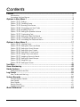
Contents
Preface...........................................................................................................2
Introduction....................................................................................................................2
Accessing the User Menus..............................................................................................3
Options in User Menu 1 ..................................................................................4
Option 1-1: Testing.....................................................................................................4
Option 1-2: Omitting Zones........................................................................................8
Option 1-3: Shunting 24hr Zones ................................................................................9
Option 1-4: Changing your User Code ....................................................................10
Option 1-5: Enabling Chimes...................................................................................11
Option 1-6: Setting the Speaker Volume ..................................................................12
Option 1-7: Customising Text ...................................................................................13
Option 1-8: Setting Up Silent Set Wards ....................................................................14
Option 1-9: Configuring Engineer Access ................................................................15
Option 1-0: Accessing the Set/Unset Menu ..............................................................16
Options in User Menu 2 ................................................................................17
Option 2-1: Viewing Zones .......................................................................................17
Option 2-2: Setting the Time and Date ....................................................................18
Option 2-3: Setting Up Shunt Groups........................................................................19
Option 2-4: Setting Up User Codes...........................................................................21
Option 2-5: Setting Up Chime Zones........................................................................32
Option 2-6: Using Communications.........................................................................33
Option 2-7: Assigning Zones to Wards ......................................................................35
Option 2-8: Setting Up Ward Groups ........................................................................36
Option 2-9: Using the Log ........................................................................................37
Option 2-0: Setting Up Timers ...................................................................................40
Text Keys.......................................................................................................48
Zone Numbering ..........................................................................................49
Radio Systems ..............................................................................................50
Telecommands and PAs ..............................................................................................50
Log Events ....................................................................................................52
User Codes and the Log ..............................................................................................56
System Records ............................................................................................57
General System Details ................................................................................................57
User Details...................................................................................................................60
Zone Details .................................................................................................................61
Service Record.............................................................................................................62
Installer Information ......................................................................................................63
Quick Reference ..........................................................................................64
1
Preface
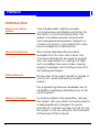
Introduction
About your Alarm
System
Your intruder alarm system provides
comprehensive and flexible protection for
domestic or commercial premises. The
system comprises several components,
such as keypads and sensors, linked to a
control unit, which is concealed from view
but accessible for maintenance.
About this Manual
This manual describes the functions
available from the two user menus. The
manual is intended to be used by people
who are responsible for carrying out tasks
such as adding new user codes, viewing
logged messages and omitting zones from
the setting procedure.
Other Manuals
Please refer to the User's Guide for details of
how to set, unset and reset your alarm
system.
The Engineering Manual (available only to
installation engineers) describes how to set
up the system.
Making Changes
2
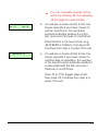
To ensure problem-free operation, discuss
the system with your alarm company before
making significant changes. It is good
practice to maintain a paper record of how
the system is set up, using the record sheets
at the back of this manual.
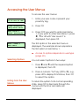
Accessing the User Menus
To access the user menus:
BANNER TEXT
17:30 Sun 01 JAN
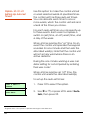
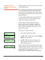
1. Enter your user code or present your
proximity tag.
0=Set Selection
[Ent]=User Level
2. Press [.
User Level 1
Press [Ent]or[2]
3. Press [ if you want to enter User Menu
1. If you want to enter User Menu 2, press
|, ¬ or 2 until "User Level 2" is
displayed, then press [.
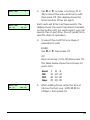
User 1 Menu 1
Test Menu
The first option in the selected menu is
displayed. The example shown opposite is
the first option in User Menu 1.
Z
Selecting Options
Access to options depends on user type
(page 22).
You can select options in two ways:
1. Press | and ¬ until the required option
is displayed, then [.
2. Press a numeric "hot" key (0 to 9), e.g.
press 2 to display Omit Zones, then [
to select the option.
Exiting from the User
Menus
To return the system to its normal operating
state, press ] to step back through the
menus until the time and date are
displayed.
3
Options in User Menu 1
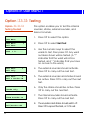
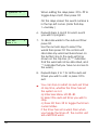
Option 1-1: Testing
Option 1-1-1:
Testing the Bell
1. Press [ to select this option.
User 1 Menu 1
Test Menu
Test Menu
Bell Test
4
This option enables you to test the internal
sounder, strobe, external sounder, and
telecommands.
1
2. Press [ to select Bell Test.
Bell test wards:
Ward > 1*......
3. Use the numeric keys to select the
wards to test, then press [. Any ward
numbers shown will be tested. (A “*”
indicates that the ward will not be
tested, and “.” Indicates that you have
no access to the ward.)
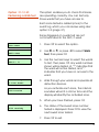
Bell Test
Bell Only
4. The external sounder should activate.
Press [ to carry out the next test.
1
Bell Test
2
Bell & Strobe ON
5. The external sounder and strobe should
be active. Press [ to carry out the next
test.
Bell Test
Strobe Only
6. Only the strobe should be active. Press
[ to carry out the next test.
3
Bell Test
4
Alarm Sounder On
7. The internal sounder should activate.
Press [ to carry out the next test.
Bell Test
0
Bell/Strobe OFF
8. The sounders and strobe should switch off.
Press [ to repeat the tests, or ] to exit.
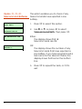
Option 1-1-2:
Performing a Walk Test
This option enables you to check that zones
are operating correctly. You can test only
those wards that you have access to.
Each zone tested is added (once) to the
event log, which you can review using User
option 2-9 (page 37).
Zones triggered on a walk test are not
communicated to the ARC, if used.
1. Press [ to select this option.
User 1 Menu 1
Test Menu
Test Menu
Walk Test
2
2. Use | or ¬, or press 2 to select Walk
Test, then press [.
Walk test wards:
Ward > 1*......
3. Use the numeric keys to select the wards
to test, then press [. Any ward numbers
shown will be tested. (A “*” indicates that
the ward will not be tested, and “.”
Indicates that you have no access to the
ward.
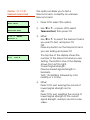
ESC To Stop Test
& View Zones
4. Walk through your wards and operate all
detection devices.
0003 Active
As you activate each zone, the internal
sounders will emit a chime tone and the
display will identify the activated zone.
5. When you have finished, press ].
Panel Zone 1
0001 Healthy
6. The status of the lowest zone number
tested is displayed. Press [ to view the
next lowest zone tested.
7. Press ] to exit.
5
Option 1-1-3:
Telecommand Batteries
This option enables you to check if any
telecommands have reported a low
battery.
User 1 Menu 1
Test Menu
1. Press [ to select this option.
Test Menu 3
Telecmd Batts
2. Use | or ¬, or press 3 to select
Telecommand Batts, then press [.
No batteries low
Either:
The display shows that all
telecommands are OK.
2:01:01 Batt Low
Martha’s
OR
The display shows the number of any
telecommands that have reported a
low battery. If you have programmed a
text name for the telecommand, the
display shows that text on the bottom
line.
3. Press [ to repeat the tests, or ] to
exit.
6
Option 1-1-4:
Telecommand Test
1. Press [ to select this option.
User 1 Menu 1
Test Menu
Test Menu
Telecmd Test
2:01:1 RNode
Martha’s
2:01:3 RNode
9(5) Bat-H
This option enables you to test a
telecommand, or identify an unknown
telecommand.
4
2. Use | or ¬, or press 4 to select
Telecmd Test, then press [.
3. Either:
Use | or ¬ to select the telecommand
you want to test, and press [.
OR:
Press any button on the telecommand
you are testing and press [.
The top line of the display shows the
number of the telecommand you are
testing. The bottom line of the display
shows (from left to right):
Current signal strength.
Previous lowest signal strength in
brackets.
”Bat-” (for Battery) followed by H for
healthy or L for low.
4. Either:
Press ] to exit, leaving the record of
lowest signal strength as it is.
OR:
Press [ to exit, resetting the record of
lowest signal strength to the current
signal strength, ready to record a new
value.
7
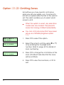
Option 1-2: Omitting Zones
Sometimes you may need to omit zones
when you set your wards, e.g. if a zone is to
remain occupied while the rest of the ward is
set. This option enables you to select which
zones to omit.
User 1 Menu 2
Omit Zones
0001 is Armed
0002 is Armed
Z
When the system is unset, any selections
made here are cleared. This prevents
zones from being omitted inadvertently.
Z
You can omit only zones that have been
set up as omittable (Engineer option
1-1).
1. Press [ to select this option.
2. Select the zone to omit by using | or ¬,
or by entering the four-digit zone
number. Refer to page 49 for details of
zone numbering.
3. Press r to change the omit status of the
zone ("Omitted" indicates that the zone
will be omitted).
4. Press [ to view the next zone, or ] to
exit.
8
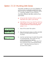
Option 1-3: Shunting 24hr Zones
This option enables you to shunt (disable) all
24 Hour zones in selected wards that have
been set up as shuntable in Engineer option
1-1. Shunting disables a zone and the
shuntable attribute identifies whether this is
permissible.
Z
Zones remain shunted until you use the
Reinstate 24hr option (see below).
Z
Reinstating zones may start the exit timer,
depending on whether Unshunt, No Exit
or Unshunt & Exit is selected (Engineer
option 1-9-1).
User 1 Menu 3
Shunt 24hr Zones
1. Press [ to select this option.
1=Shunt 24Hr
2=Reinstate 24hr
2. Press 1 to shunt zones or 2 to reinstate
zones that have been previously
shunted.
Shunt Wards
Ward > 1*......
3. Use the numeric keys to select the wards
to shunt/reinstate, then press [. Any
ward numbers shown will be
shunted/reinstated. (A “*” indicates that
the ward will not be shunted/reinstated,
and “.” Indicates that you have no
access to the ward.)
9
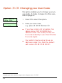
Option 1-4: Changing your User Code
This option enables you to change your own
user code. To make changes for other users,
refer to page 21.
1
User 1 Menu 4
Change Code
1. Press [ to select this option.
Enter new code..
----
2. Enter your new code,
e.g. press 5 6 7 8, then [.
Z
If your new code is not accepted, the
display shows "NOT ACCEPTED try a
different code". This usually means that
the code is already in use. Press r enter
the code again.
Z
Your system may be set up to use six
digit user codes. If so, then the default
user code is 5 6 7 8 0 0 1.
Requires option 01 to be set to “6 digit codes” in Engineer menu 1-9-3.
10
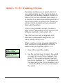
Option 1-5: Enabling Chimes
This option enables you to select which of
your wards (if any) use the chime feature. In
a ward with this feature enabled, zones that
have a Chime Tone attribute (User option 25) and are in a selected ward will generate a
chime tone when activated. The wards then
remain chime-enabled until you deselect
them with this option.
A zone may generate a single, double or
triple chime, depending on the Chime Tone
attribute selected in User option 2-5.
The chime occurs only at keypads and
extension loudspeakers assigned to the
same ward(s) as the zone.
When a chime occurs, keypads display the
zone number if configured by the Chime
Visible setting in Engineer option 1-9-1.
User 1 Menu 5
Enable Chime
1. Press [ to select this option.
Chime on wards:
Ward > 1*......
2. Use the numeric keys to select the wards
you want to have chime enabled, then
press [. Any ward numbers shown will
be chime enabled. (A “*” indicates that
the ward will not be chime enabled, and
“.” Indicates that you have no access to
the ward.)
11
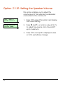
Option 1-6: Setting the Speaker Volume
This option enables you to adjust the
volume level of the extension loudspeaker
connected to the control unit.
User 1 Menu 6
Volume Control
1. Press [ to select this option and display
the current setting.
Volume Control
>>>>>>> (MAX)
2. Press | and ¬, or enter a value (0 to 7),
to adjust the volume, from ‘Sound Off’
up to maximum.
3. Press [ to accept the displayed value
or ] to exit without change.
12
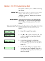
Option 1-7: Customising Text
This option enables you to edit the following
text strings:
Banner Text This message is shown on the top line of the
display when the keypad is in normal
"standby" mode (i.e. waiting for a code to
be entered).
Group Names These are the names of the ward groups
(see page 36). The names are displayed
when setting ward groups (see the User's
Guide).
Telecommand Text These are the names of any telecommands
that the installer has allocated to your
system.
1. Press [ to select this option.
User 1 Menu 7
Customise Text
Custom Text
Banner Text
1
Viewing Group
1
^iewing Group
1
2. Use | or ¬, or press a hot key (1 , 2,
or 3), to select the text string to edit,
then press [.
3. If you have chosen to edit group
names, use | or ¬, or press a hot key
to select the group name to edit, then
press [.
4. Use the text editing keys (page 48) to
change the text if required. Press [ to
accept the displayed text or ] to exit
without change.
13
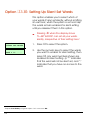
Option 1-8: Setting Up Silent Set Wards
This option enables you to select which of
your wards (if any) set silently, without emitting
an exit tone, when the system is set normally.
The wards remain enabled for silent setting
until you deselect them in this option.
Z
1
Pressing 8 when the display shows
"0=SET WARDS" can set all your wards
silently, irrespective of their setting here1.
User 1 Menu 8
Silent Set Wards
1. Press [ to select this option.
Silent set wards
Ward > **......
2. Use the numeric keys to select the wards
you want to enable for silent setting, then
press [. Any ward numbers shown are
enabled for silent setting. (A “*” indicates
that the ward will not be silent set, and “.”
Indicates that you have no access to the
ward.
Requires P.Set Hotkey in Engineer option 1-9-1 to be set to NO
14
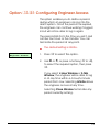
Option 1-9: Configuring Engineer Access
This option enables you to define a period
during which an engineer can log into the
alarm system. Once the period has expired,
the engineer can continue working if logged
in but will not be able to log in again.
The period starts from the time you set it and
can be four hours or five minutes. You can
terminate the period at any point.
Z
User 1 Menu 9
Engineer Access
The default setting is Infinite.
1. Press [ to select this option.
2. Use | or ¬, or press a hot key (1 to 4),
to select the required option, then press
[.
If you select 4 Hour Window or 5 Min
Window, the engineer will be able to log
in at any time within a 4-hour/5-minute
period from now. Selecting Infinite allows
the engineer access at any time.
Selecting Close Window terminates any
period currently running.
15
Option 1-0: Accessing the Set/Unset Menu
The set/unset menu is displayed whenever
you enter your user code or present your
proximity tag. This option enables you to
access this menu from User Menu 1.
The Set/Unset Menu has several options, but
only relevant ones are shown, e.g. if all wards
are unset, the option to unset wards is not
shown.
For information about setting, unsetting and
resetting the system, refer to the User's Guide.
16
Options in User Menu 2
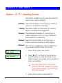
Option 2-1: Viewing Zones
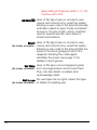
This option enables you to view the status of
each zone, which may be:
Healthy The normal status of a zone (e.g. a door is
closed or a detector inactive).
Active The alarm status of a zone (e.g. a door is
open or a detector is triggered).
Tamper The interference status of a zone (e.g. a
cable has been cut or a cover has been
removed from a detector).
Shorted The short-circuit status of a zone (e.g. a
cable has been shorted or damaged).
Masked The sensor is masked by some obstruction
(e.g. boxes stacked near the sensor).
User 2 Menu 1
View Zones
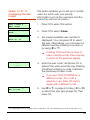
1. Press [ to select this option.
Panel Zone 1
0001 Healthy
2. Press | or ¬ to scroll to the zone you
want to view, or enter the zone's fourdigit number. See page 49 for details of
zone numbering.
Z
You can press r to choose the
zone on the next network. However,
if you keep scrolling, you will reach
all zones anyway.
3. Press ] to return to User Menu 2.
17
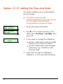
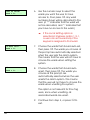
Option 2-2: Setting the Time and Date
This option enables you to set the system
time and date.
Z
1. Press [ to select this option.
User 2 Menu 2
Time and Date
Time and Date
Set Time
Enter new time:11:44
The system automatically
advances/retards the time by one hour
at 1 am GMT on the standard
summer/winter changeover dates.
1
2. Use | or ¬, or press a hot key (1 or
2) to select Set Time or Set Date, then
press [.
3. If you need to change the date/time:
•
•
For the current time, enter four digits
(hhmm), e.g. 1810 for 6:10pm.
For the current date, enter six digits
(ddmmyy), e.g. 181005 for 18th
October 2005.
4. Press [ to accept the displayed
date/time, or ] to exit without saving.
18
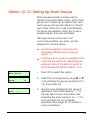
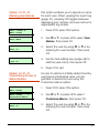
Option 2-3: Setting Up Shunt Groups
Shunt groups provide a simple way to
isolate zones until further notice. Each shunt
group can contain up to eight zones, and
each group can be allocated to a "Shunt"
user code. When the code is first entered,
the zones are isolated. When the code is
entered again, they are reinstated.
Although 24-hour zones are most
commonly isolated, any zone can be
assigned to a shunt group.
Z
Any zone selected must have the
Shuntable attribute set in Engineer
option 1-1.
Z
Entering a shunt code to reinstate zones
may start the exit timer, depending on
whether Unshunt, No Exit or Unshunt &
Exit is selected (Engineer option 1-9-1).
User 2 Menu 3
Edit Shunts
1. Press [ to select this option.
Edit Shunt Grps
Group
01
2. Select the shunt group by using | or ¬,
or by entering the group number (01 to
10), then press [.
Group 01 Zone >1
Zone ----
3. The first zone assigned to the group is
displayed. This is indicated by ">1" in
the top-right corner. The bottom line
indicates the zone number, or "----" if a
zone number has not yet been
specified. (See page 49 for details of
zone numbering.)
19
You can view any of the eight possible
zones assigned to the group by using |
or ¬, or pressing the hot key (1 to 8).
If you want to delete the displayed zone
from the shunt group, press r, then ].
You can delete more than one zone by
scrolling to each in turn and pressing
r, then finally pressing ].
Group 01 Zone >1
Zone >----
4. Press [ if you want to edit the zone
number. You will see that the bottom
line contains a ">" to indicate that you
are in edit mode.
5. After entering the zone number, press
[ to save changes. Alternatively, press
] to exit without saving.
6. Now you can do one of the following:
•
•
•
20
Continue from step 3 to specify
more zones in the shunt group.
Press ] to return to step 2, which
allows you to set up another shunt
group.
Press ] twice to exit from the option.
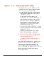
Option 2-4: Setting Up User Codes
This option allows you to define users to
operate the alarm system. When setting
up a user, you need to specify:
• A user code. This is the code that the
user enters at keypads (e.g. to set or
unset the system).
• A user type (e.g. Manager). This
determines, for example, the range of
user options the person can access.
The user’s access to menu options is
initially determined by the user type
selected, but can be customised, if
required (see page 27).
• The wards the user is assigned to. Users
can set, unset and reset only the wards
assigned to them.
• Whether certain wards set or unset
automatically during a set/unset.
Z
A user cannot set up or modify users
with a lower user number (e.g. User 03
cannot modify User 02).
Z
To delete a user, set the user type to
"Not in use".
This option also allows you to program the
functions of telecommand buttons. You
can program individual buttons to set
various setting groups, and unset wards.
You can allocate the PA function to specific
wards, and give the telecommand a
meaningful name.
21
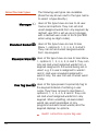
About the User Types
Manager 1
Standard Global 2
The following user types are available.
(Press the key shown next to the type name
to select a type directly.)
Users of this type have access to all user
menus and options. They can set and
unset assigned wards from any keypad. By
default, user 001 is set up as a manager,
with a default user code of 5678 (567800
when using six-digit codes).
Users of this type have access to User
Menu 1, options 0, 1, 2, 3, 4, 5, 8 and 9.
They can set and unset assigned wards
from any keypad.
Standard Ward 3 Users of this type have access to User Menu
1, options 0, 1, 2, 3, 4, 5, 8 and 9. They can
only set and unset assigned wards from a
keypad assigned to the wards being set or
unset, e.g. if a user is assigned to wards 1
and 2, and uses a keypad assigned to
ward 2 only, the user can set or unset ward
2 only.
Prox Tag User 4 Users of this type present a proximity tag to
the keypad instead of entering a user
code. They have access to User Menu 1,
options 0, 1, 2, 3, 4, 5, 8 and 9. They can
set and unset assigned wards from any
keypad. When unsetting, all associated
wards are unset (regardless of any
programmed auto-unset wards) and the
keypad displays no options.
Z
22
User01 cannot be a prox tag user.
Easy Set 5 When unsetting, all associated wards are
unset and the keypad displays no options.
The system sets with no options, providing
auto-set wards are set up. The user can
set/unset from any keypad.
Z
You must set up wards assigned to an
Easy Set user as auto-set and autounset, see page 26 onwards.
Reset Only 6 Users of this type have access to User Menu
1, options 1, 2, 3, 4, 5, 8 and 9. They can
reset 24-hour alarms from any keypad.
Panic Code 7 Users of this type have no access to user
menus and cannot set or unset the system.
Entering a user code of this type generates
a Panic Alarm and activates a full alarm
(causing internal and external sounders and
strobe lights to operate).
Z
To set up a Panic code, Duress Allow in
Engineer option 1-9-1-24 must be set to
YES.
Duress Code 8 Users of this type have the same abilities as
a standard global user but, when the user
code is entered, a silent alarm is
generated1, which could be sent to an
alarm receiving centre. This enables the
user to appear to operate the alarm system
normally if being coerced.
Z
To set up a Duress code, the Duress
All
tti i E i
ti 1 9 1 24
1
Outputs of type "Duress Alarm" are activated if the system is being set. Outputs of type "Duress Alarm" or "Panic
Alarm" are activated if the system is being unset.
23
Allow setting in Engineer option 1-9-1-24
must be set to YES.
Access 9 Users of this type have no access to user
menus and cannot set or unset the system.
Entering a user code of this type temporarily
activates outputs of type "Code Accepted",
Access or "Access Code", which could be
used to operate electric door strikes or
similar mechanisms.
Shunt Users of this type have no access to user
(No hotkey available.) menus and cannot set or unset the system.
Entering a user code of this type isolates the
zones in the shunt group(s) to which it is
assigned. Entering the code again
reinstates the zones. See page 19 for
details of shunt groups.
Set Only Users of this type can set assigned wards
(No hotkey available.) from any keypad but cannot unset them.
They can also disarm sounders and
acknowledge alerts.
Not in use This user type has no rights. Select this type
(No hotkey available.) to delete an existing user.
24
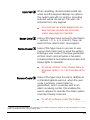
Option 2-4-1:
Configuring the User
Codes
1. Press [ to select this option.
User 2 Menu 4
Edit Codes
User Codes
Code
This option enables you to set up or modify
users. For each user, you specify
information such as the user type and the
wards the user has access to.
1
Define new users
User no. 05
2. Press [ to select Code.
3. The lowest available user number is
displayed. You can press [ to select
this user. Alternatively, you can select a
different user by entering a number or
by using | or ¬.
Z
Prox Tag or Code
----
4. Enter the user code1 and press [, or
present the user's proximity tag. Pressing
[ without entering a code maintains
the previously-chosen code.
Z
User 05 is type
Not in use
1
Pressing r shows the number of
users currently set up. Press any key
to return to the previous display.
If you see “NOT ACCEPTED try a
different code”; the code is
already in use. Press r and try
again with a different code.
5. Use | or ¬ or press a hot key (0 to 9)
to select the user type (page 22), then
press [.
4 or 6 digits (giving up to 1,000,000 code combinations, with none disallowed), as set up in Eng option 1-9-3.
25
User 05 wards
Ward > 1*......
6. Use the numeric keys to select the
wards you want the user to have
access to, then press [. Any ward
numbers shown will be allocated to the
user. (A “*” indicates that the ward will
not be allocated, and “.” Indicates that
you have no access to the ward.)
Z
If the Local Setting option is
selected in Engineer option 1-9-1,
a user can set a ward only if the
keypad is assigned to that ward.
05 Auto Sets:Ward > 1*......
7. Choose the wards that should auto-set,
then press [. The wards you choose at
this prompt are automatically selected
when the user sets the alarm system.
This means that the user will not have to
choose the wards when setting the
system.
05 Auto Unset:Ward > 1*......
8. Choose the wards that should autounset, then press [. The wards you
choose at this prompt are
automatically selected when the user
unsets the alarm system. This means
that the user will not have to choose the
wards when unsetting the system.
This option is not relevant for Prox Tag
users, since when unsetting, all
associated wards are unset.
9. Continue from step 3, or press ] to
exit.
26
Option 2-4-2:
Defining User Names
1. Press [ to select this option.
User 2 Menu 4
Edit Codes
User Codes
User Name
This option enables you to specify a name
for each user. When viewing the event log
(page 37), pressing r toggles between
displaying user number and user name for
appropriate log entries.
2
2. Use | or ¬ or press 2 to select User
Names, then press [.
User 01
User 01
3. Select the user by using | or ¬ or by
entering the user number, then press
[.
User 01
^ser 01
4. Use the text editing keys (page 48) to
edit the user name, then press [.
5. Press ] to exit.
Option 2-4-3:
Customising Access to
Menu Options
Access to options is initially determined by
user type but individual users can be
granted or denied access using the
Customise Menus option.
User 2 Menu 4
Edit Codes
1. Press [ to select this option.
User Codes
3
Customise Menus
2. Use | or ¬ or press 3 to select
Customise Menus, then press [.
User 01
User 01
3. Select the user by using | or ¬ or by
entering the user number, then press
[.
27
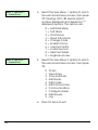
Menu 1 Options:> 0123456789
4. Select the User Menu 1 options to which
the user should have access, then press
[. Pressing 0 to 9 selects (option
number displayed) and deselects (“*”
displayed) options. The options are:
0 = Set/Unset Menu
1 = Test Menu
2 = Omit Zones
3 = Shunt 24hr Zones
4 = Change Code
5 = Enable Chime
6 = Volume Control
7 = Customise Text
8 = Silent Set Wards
9 = Engineer Access
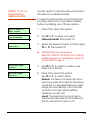
Menu 2 Options:> 0123456789
5. Select the User Menu 2 options to which
the user should have access, then press
[.
0
1
2
3
4
5
6
7
8
9
Timers
View Zones
Time and Date
Edit Shunts
Edit Codes
Edit Chime Zones
Communications
Configure Wards
Edit Groups
Log
6. Press ] twice to exit.
28
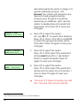
Option 2-4-4:
Programming
Telecommands
2:01:1 RNode
Telecmd 1
Cooper Security Limited recommend that
you take advice from your alarm installer
before modifying any of these options.
1. Press [ to select this option.
User 2 Menu 4
Edit Codes
User Codes
Telecommands
Use this option to allocate telecommand or
PA buttons to individual wards.
4
2. Use | or ¬ or press 4 to select
Telecommands then press [.
3. Select the telecommand or PA by using
| or ¬, then press [.
Z
At this point you can press a
telecommand or PA button to make its
details appear on the display. Press [
to proceed to step 4.
>Telecmd Type
Global
4. Use | or ¬ to select an option (see
steps 5 to 9 below).
Telecmd Type
>Global
5. Press [ to select this option.
Use | or ¬ to select either:
Global: The telecommand can set or
unset any ward allocated to its buttons,
anywhere on site (depending on radio
range and conditions). A PA can start
an alarm in its allocated partition,
anywhere on site. OR:
Local: The telecommand can set or
unset wards allocated to its buttons (or
the PA can start an alarm in its
29
allocated ward) only when in range of a
specific MRNode receiver1. OR:
Unused: The control unit will ignore any
telecommand programmed as
Unused, even though it may still be
learned by an MRNode. (Hint: Use this
option to disable telecommands that
have been lost.) Press [ to save your
changes.
Button 1 ^Set
Group 1> 1*******
6. Press [ to select this option.
(Or, use | or ¬ to select other buttons.)
Press 1 to 4 (or 1 to 8 on a M2000)
to select the group that will be set by
the button. Press [ again to save your
changes.
Button 4 vUnset
Ward >1*******
7. Press [ to select this option.
Press 1 to 8 to select the wards that
will be unset by button 4. (By default
button 4 unsets all wards.) Press [
again to save your changes.
Button
PA
Ward
1*******
8. Press [ to select this option.
Press 1 to 8 to select the wards that
will be sent into alarm by a PA (button 1
and 4). Press [ again to save your
changes.
Z
1
722r and 727r telecommands can start
PAs, 723r and 728r cannot start PAs.
The installer must allocate partitions to individual MRNodes.
30
Telecmd 1
^elecommand Name
9. Press [ to select this option.
Use the text editing keys (page 48) to
edit the telecommand name, then
press [ to save your changes.
31
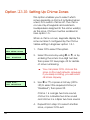
Option 2-5: Setting Up Chime Zones
This option enables you to select which
zones generate a chime if activated when
unset, or to switch chimes off. The chime
occurs only at keypads and extension
loudspeakers assigned to the same ward(s)
as the zone. Chimes must be enabled in
User option 1-5.
When a chime occurs, keypads display the
zone number if configured by the Chime
Visible setting in Engineer option 1-9-1.
User 2 Menu 5
Edit Chime Zones
1. Press [ to select this option.
Chime Zone:
0001 Disabled
2. Select the zone by using | or ¬, or by
entering the zone's four-digit number,
then press [. See page 49 for details
of zone numbering.
Z
Chime Zone:
0001 >Disabled
You can press r to choose the
zone on the next network. However,
if you keep scrolling, you will reach
all zones anyway.
3. Use | or ¬, or press a hot key (0 to
3) to select the required chime (or
"Disabled"), then press [.
Chime 1 is a single two-tone sound,
chime 2 is a double two-tone sound
and chime 3 is a triple two-tone sound.
4. Repeat from step 2 to select another
zone, or press ] to exit.
32
Option 2-6: Using Communications
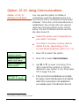
Option 2-6-1:
Starting a Call Back
1
You can use this option to initiate a
connection over the telephone line to a
remote site that is running the Downloader
software1. Once the communication link is
established, the remote site can upload
data and change settings in the control
panel. The link continues until the remote
site disconnects it.
Z
Select this option only if requested by
your alarm company.
Z
Your alarm company may be able to
initiate the link, depending on the
Access Mode (Engineer option 2-5-1-3).
User 2 Menu 6
Communications
1. Press [ to select this option.
Communication 1
Start Call Back
2. Press [ to select Start Call Back.
Start CallBack 1
08700543678
3. Use | or ¬, or press a hot key (1 to
4) to select the number to call (as
defined in User option 2-6-2), then press
[ to begin the call.
Calling On :
1
Hit ESC to abort
4. If the connection is established successfully,
the system automatically returns to its original
state. If the connection is not established
successfully, press ] to abandon the call.
Not available on M750 and M550 systems
33
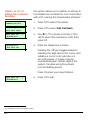
Option 2-6-2:
Editing the Call-Back
Numbers
This option allows you to define or edit up to
four telephone numbers for communication
with a PC running the Downloader software1.
User 2 Menu 6
Communications
1. Press [ to select this option.
Communication 2
Edit Call Back
2. Press [ to select Edit Call Back.
Edit Call No.
08700543678
3. Use | or ¬, or press a hot key (1 to
4) to select the number to edit, then
press [.
1
4. Enter the telephone number.
08700543678
^dit Call No.
Pressing the r key toggles between
deleting the digit above the cursor and
adding a comma (to indicate a 4second pause). A pause may be
needed between certain digits if the
system mis-dials using the panel's
normal dialling speed.
Press [ when you have finished.
Edit Call No.
08700543679
1
1
5. Press ] to exit.
Not available on M750 and M550 systems
34
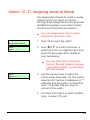
Option 2-7: Assigning Zones to Wards
The assignment of zones to wards is usually
carried out by your alarm company.
Change these assignments only if you have
detailed knowledge of your alarm system
and the way that wards are used in it.
Z
You can assign zones only to wards
assigned to your user code.
User 2 Menu 7
Configure Wards
1. Press [ to select this option.
0001
Ward : 1.......
2. Press | or ¬ to scroll to the zone, or
enter the zone's four-digit number, then
press [. See page 49 for details of
zone numbering.
Z
0001
Ward > **......
You can press r to choose the
zone on the next network. However,
if you keep scrolling, you will reach
all zones anyway.
3. Use the numeric keys to select the
zone's wards, then press [. The ward is
selected if its number is displayed. (A “*”
indicates that the ward is not selected,
and “.” Indicates that you have no
access to the ward.)
4. Continue from step 2 to select another
zone, or press ] to exit.
35
Option 2-8: Setting Up Ward Groups
This option enables you to allocate wards to
groups, which you can then set or unset with
a single operation (as described in the User's
Guide).
Z
You can select only those wards that
are assigned to your user code.
Z
You can name each ward group using
User option 1-7 (page 13).
User 2 Menu 8
Edit Groups
1. Press [ to select this option.
Viewing Group
1
Ward : ........
2. Use | or ¬, or press a hot key (e.g. 4)
to select the ward group to edit, then
press [.
Editing Group
1
Ward > **......
3. Use the numeric keys to select the
wards to assign to the group, then press
[. Any ward numbers shown are
assigned to the group. (A “*” indicates
that the ward will not be assigned, and
“.” Indicates that you have no access to
the ward.)
4. Continue from step 2 to select another
ward group, or press ] to exit.
36
Option 2-9: Using the Log
Option 2-9-1:
Viewing the Log
This option enables you view the contents of
the system log. The log contains the date
and time of system events, such as wards
being unset, zones omitted, duress code
activations and communications problems.
For more information about the event
codes displayed, see page 52.
The number of events recorded in the log is
model specific.
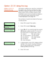
1. Press [ to select this option.
User 2 Menu 9
Log
Log Functions
View Log
1
2. Press [ to select View Log.
UNSET WARDS:
10:50:10 23/04
3. Press | or ¬ to scroll through the events
(| displays earlier events). To move to
the next event of a given type, press:
1 Alarms
6 User codes
2 24 Hour Alarms 7 Set Wards
3 Fire Alarms
8 UnSet Wards
4 PA Alarms
9 Entry
5 Zone Tampers
Ward : 12......
10:50:10 23/04
4. If appropriate, press r to display further
details of the event. Pressing 0 allows
you to view events from a specified
offset (position) in the log.
5. Press ] to exit.
37
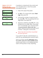
Option 2-9-2:
Printing the Log
1. Press [ to select this option.
User 2 Menu 9
Log
Log Functions
Print Log
If a printer is connected to the control unit,
you can print some or all of the events
recorded in the log.
2
2. Use | or ¬, or press 2 to select Print
Log, then press [.
How many events?
0030
3. Choose the number of events to print
by using | or ¬, or by entering the fourdigit value, then press [.
With offset of:0030
4. Specify an offset by using | or ¬, or by
entering the four-digit value, then press
[. If, for example, you choose to print
10 events and an offset of 50, the
system will print events 50-59 (with event
number 1 being the most recent).
Z
There may be more than one printed
line per log event.
If you want to stop the current print job, reprint the log, specifying zero events to print.
Once you have used the Print Log option,
the system goes into online printing mode,
where every action is immediately printed.
Switch off the printer to stop all printing.
38
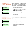
Option 2-9-3:
Viewing the Access Log
You can use this option to view the content
of the access log, which stores every use of
a user code of type Access (which is used
to open doors).
User 2 Menu 9
Log
1. Press [ to select this option.
Log Functions 3
View Access Log
2. Use | or ¬, or press 3 to select View
Access Log, then press [.
Name :- User 02
02:35:48 01/05
3. Use | or ¬ to scroll through the events
(| displays earlier events).
4. Press ] to exit.
Option 2-9-4:
Printing the Access Log
You can use this option to print the access
log.
User 2 Menu 9
Log
1. Press [ to select this option.
Log Functions 4
Print Access Log
2. Use | or ¬, or press 4 to select Print
Access Log, then press [.
How many events?
0030
3. Follow the same procedure as for
option 2-9-2.
39
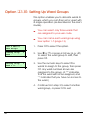
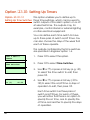
Option 2-0: Setting Up Timers
Option 2-0-1:
This option enables you to define up to
Setting Up Time Switches three time switches, which can be used to
switch outputs of the alarm system on or off
at selected times. The outputs may, for
example, control internal or external lighting
or other electrical equipment.
You can define each time switch to have
up to three pairs of switch on/off times. You
can also choose the days of the week that
each of these operate.
The outputs controlled by the time switches
are specified in Engineer option 1-4.
1. Press [ to select this option.
User 2 Menu 0
Timers
Timers
Time Switches
1
2. Press [ to select Time Switches.
Time Switch
1
3. Use | or ¬, or press a hot key (e.g. 3)
to select the time switch to edit, then
press [.
Time Switch
1
On (1)
00:00
4. Use | or ¬, or press a hot key (1 to
9) to select the on/off time or days of
operation to edit, then press [.
Each time switch has three pairs of
switch on/off times. For each of these,
you will notice that there is an option to
specify the on time, one to specify the
off time and another to specify the days
of operation.
40
Z
Time Switch
1
On (1)
>00:00
You can manually override a time
switch by pressing 0, then pressing
r to toggle its current status.
5. You will see a screen similar to the one
shown opposite if you have chosen to
edit an on/off time. The number in
brackets indicates whether it is in the
first, second or third pair of on/off times.
Enter the time in 24-hour format, (e.g.
2100 for 9:00pm), then press [.
Continue from step 4 or press ] to exit.
1 Operates On :> ..............
6. You will see a screen similar to the one
shown opposite if you have chosen to
edit the days of operation. The number
in the top-left corner indicates whether it
is associated with the first, second or
third pair of on/off times.
Press 1 to 7 to toggle days on/off,
then press [. Continue from step 4 or
press ] to exit.
41
Option 2-0-2:
Setting Up Auto-Set
Timers
Use this option to make the control unit set
or unset selected wards at specified times.
The control unit has three auto-set timers.
You can allocate each timer to one or
more wards, which the control unit sets and
unsets at the times you chose.
For each auto-set timer you can specify up
to three events. Each event comprises a
switch on (set) time, an off (unset) time, and
a day of the week.
When a timer reaches the “on” time for an
event the control unit operates the keypad
sounders for one minute and then sets the
allocated ward(s). Note that the control unit
will not set any ward where there is an
active detector.
During the one minute warning a user can
defer setting for a short period by entering
their user code1.
When a timer reaches an “off” time, the
control unit unsets the allocated ward(s).
To set up the auto-set timers:
1. Press [ to select this option.
User 2 Menu 0
Timers
Timers
Auto-Sets
1
2
2. Use | or ¬, or press 2 to select AutoSets, then press [.
Engineer menu 1-5-2 option 16 specifies the length of the defer time.
42
Auto Set
1
Auto Set
On (1)
1
00:00
3. Use | or ¬, or press a hot key (1 to
3) to select the auto-set timer to edit,
then press [. (The display shows the
timer number at the top right.)
Each auto-set timer has three events. The
display shows the event number in brackets
on the bottom left. For each event, you can
specify the on (set) time, the off (unset) time
and the days of operation.
4. To select the on/off time or days of
operation to edit,
EITHER
Use | or ¬ then press [.
OR
Press a hot key (1 to 9) then press [.
The table below shows the hot keys for
each item:
Event 1 2 3
ON
1 2 3
OFF
4 5 6
Days 7 8 9
Auto Set
On (1)
1
>00:00
5. When editing times, enter the time in
24-hour format, (e.g. 2100 for
9:00pm), then press [.
43
When editing the days press 1 to 7 to
toggle days on/off, then press [.
1 Operates On :> ..............
On the days screen the event number is
in the top-left corner. (Note that day
1=Sunday.)
6. Repeat steps 4 and 5 for each event
you wish to program.
Auto Set
Ward > **
1
7. To allocate wards to the auto-set timer
press r.
Use the numeric keys to select the
wards then press [. The control unit
allocates any ward numbers shown on
the bottom line to the auto-set timer
shown on the top line. (A “*” indicates
that the ward will not be allocated, and
“.” Indicates that you have no access to
the ward.)
8. Repeat steps 3 to 7 for all the auto-set
timers you wish to edit, or press ] to
exit.
Z
44
You can stop or restart an auto-set timer
at any time, whether the timer has set
the system or not.
a) Enter User Menu 2-0-2.
b) Select the auto-set timer you wish to
stop.
c) Press 0, then r to toggle the timer’s
current status.
If the timer has set a ward, then when
you toggle the timer off, the control unit
will unset that ward.
Option 2-0-3:
Setting Up Code-Locks
Timers
Use this option to lock out one or more users
at specified times.
The control unit has three code-lock timers.
You can allocate each timer to up to ten
users. Each timer prevents the system from
accepting the allocated users' codes at the
specified times.
If a user enters his/her user code while the
code-lock timer is on, the display shows
"Sorry. Your code is locked out".
Each code lock timer has up to three
events. Each event contains a switch on
time (codes not accepted), a switch off
time (codes accepted), and one or more
days of the week.
To set up a code lock timer:
1. Press [ to select this option.
User 2 Menu 0
Timers
Timers
Code Locks
3
2. Use | or ¬, or press 3 to select Code
Locks, then press [.
Code Lock
1
3. Use | or ¬, or press a hot key (1 to
3) to select the code-lock timer to
edit, then press [.
Codelock Group 1
On (1)
00:00
Each code lock timer has three events. The
display shows the event number in brackets
on the bottom left. For each event, you can
specify the on (locked) time, the off
(unlocked) time and the days of operation.
45
4. To select the on/off time or days of
operation to edit,
EITHER
Use | or ¬ then press [.
OR
Press a hot key (1 to 9) then press [.
The table below shows the hot keys for
each item:
Event 1 2 3
ON
1 2 3
OFF
4 5 6
Days 7 8 9
Codelock Group 1
On (1)
>00:00
1 Operates On :> ..............
5. Enter the time in 24-hour format, (e.g.
2100 for 9:00pm), then press [.
When editing the days press 1 to 7 to
toggle days on/off, then press [.
On the days screen the event number is
in the top-left corner. (Note that day
1=Sunday.)
Lock 1
User>03
99 Not used
6. Press r, then use | or ¬ (or enter a
two-digit number) to select which of the
ten user "slots" to edit, then press [. The
number shown in the top-right corner
shows which of the ten you are editing.
Select the user by entering his/her user
number (or use | or ¬ to scroll), then
press [.
46
You can now:
•
Continue with step 6 to specify other
users as necessary.
•
Press ] and continue from step 4.
•
Press ] twice to exit.
47
Text Keys
The following table shows how to obtain characters when entering text
at the keypad. For example, press 2 twice to obtain the "B" character.
Once you have chosen the character you require, press | to move the
cursor to the right to edit the next character. The ¬ key moves the
cursor to the left.
Note: When you reach the end of the character sequence, the next
press of the same key takes you back to the beginning of the
sequence. For example, the eighth press of the 2 key displays the "A"
character.
Key
1 .
2 A
3 D
Z
48
Characters Generated (in Sequence)
,
B
?
C
!
2
1
a
@
b
"
c
E
F
3
d
e
f
4 G
5 J
6 M
H
I
4
g
h
i
K
N
L
O
5
6
j
m
k
n
l
o
7 P
8 T
Q
R
S
7
p
q
U
V
8
t
u
v
9 W
X
0 <sp> 0
0 <sp> 0
Y
Z
9
w
x
,
#
*
,
#
*
-
&
r
s
y
z
'
Note: <sp> represents the space character.
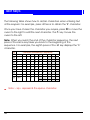
Zone Numbering
Each zone has a unique 4-digit number. The meaning of the number is
as follows:
For all zones except those using iD Plus biscuits (on an M800iD Plus):
•
•
The first digit is the network number. This is the network number of
the device that the zone is connected to (0 for zones connected to
the control unit PCB). The number of available networks depends on
the type of control unit.
The next two digits specify the device address that the zone is
connected to (00 for zones connected to the control unit PCB). For
devices such as keypads, the device address is determined by a
link on the device PCB.
Z
•
The first eight zones on an ID Node have device address 01,
the next eight have device address 02, etc.
The final digit specifies the zone number on the selected device.
Example: 2031 is (reading right to left): zone 1 of device address 03
connected to network 2.
For zones using iD Plus biscuits (on an M800iD Plus):
•
•
The first digit is always "2" (represents an imaginary network number
of 2).
The next three digits specify the zone number.
Only valid zone numbers are displayed as you scroll. For example, if you
are programming an M1000, the next number displayed after 0008
(panel zone 8) is 1011 (network 1, device 01, zone 1).
49
Radio Systems
You security system may be fitted with a
radio receiver (called an MRNode) that
‘listens’ for signals from wire-free detectors
and other transmitters, and reports their
activity to the control unit.
The control unit treats the wire free detectors
as standard zones. All the options described
in the existing Manager’s Manual work with
wire free detectors in the same way as with
wired detectors.
Telecommands and PAs
The MRNode also detects signals from small
portable transmitters, called
“telecommands” and “PAs”. PA is short for
“personal attack”, “panic alarm”, or
“personal assistance”.
A telecommand is a remote control for your
security system. By pressing buttons on a
telecommand you can set and unset the
system from outside the premises. Later
sections of this booklet tell you how to
program the buttons of individual
telecommands. (Note that the installer may
put some restrictions on exactly how you
can use a telecommand.)
A “PA” is a transmitter whose function is
purely to start a PA alarm. This type of
transmitter cannot set or unset the system.
Frequently PA transmitters have only one or
two buttons. You do not have to carry out
50
any programming of PA buttons, but you
can give them a name and allocate them
to individual wards.
Telecommand Buttons
The 722r, 723r, 727r and 728r
telecommands have four buttons that you
may program for separate functions.
The control unit identifies each button on a
telecommand by a number. The keypad
display indicates these buttons by showing
the numbers followed one of the symbols
“^, <, > or v” to indicate the position of the
button on the telecommand, as shown on
the left.
On a 722r and 727r, pressing buttons 1 and
4 at the same time generates a PA signal.
This feature is not present on a 723r and
728r.
Telecommand/PA Numbering
The keypad display shows the identity of a
telecommand or PA as a unique number,
accompanied by a text name. The number
has the format Network:Node:Device. For
example, the first telecommand learned by
MRNode 2 on Network 1 has the number:
1:02:1. In many options you can select a
telecommand or PA by keying in this
number (without the “:”).
You can program the text name yourself, as
described on page 31.
51
Log Events
Event
--- NO EVENT --### LECS or REMS
### NODE R# ADD
### NODE R# LOST
### NODE R# TAMP
### NODE'S
### XNODE'S
#### OFF TEST
#### OMITTED
#### REINSTATED
#,## AUX FAULT
#,## LEC LOST
#,## LEC TAMPER
#,## NODE ADDED
#,## NODE FUSE
#,## NODE LOST
#,## NODE TAMPER
#,## PSU FUSE
#:## PSU TAMP
#,## REM ADDED
#,## REM LOST
#,## REM TAMPER
#:## RF CLEAR
#:## RF JAMMED
#,## XNODE ADDED
#,## XNODE FUSE
#,## XNODE LOST
#,## XNODE TAMP
24 Hr WARDS:24H RESTORE ####24Hr ALARM ####
24HR OMIT:24HR REINST:ABORT ON WARDS:ACCESS ####
ACCESS FAILED
ACCESS ZONE ####
ALARM ####
ALARM WARDS:
ATE L.F. ALL
ATE L.F. RESTORE
ATE L.F. SINGLE
AUTOSET # OFF
AUTOSET # ON
AUX RESTORE ####
BELL TAMPER
AUXILIARY ####
AUXILIARY # TAMP
AUXILIARY FUSE
BATTERY FAULT
BATTERY LOAD TST
BATTERY LOW
BATTERY MISSING
BATTERY RESTORE
52
Description
Not used
The number of LEC or keypads logged on to system after a re-learn
Keypad added to MNode/XNode. First # is the network No. Next ## is the device No. R# is
the keypad No.
Keypad removed from MNode/XNode
Tamper on keypad attached to MNode/XNode
The number of Nodes logged on to the system after a re-learn
The number of XNodes logged on to the system after a re-learn
Zone number #### taken off test
Zone number #### omitted
Zone number #### reinstated
Network #, device No. ## MSPSU Aux fuse active
(this record may appear together with “#,## PSU FUSE”)
Network #, device No. ## is a LEC that has been removed
Network #, device No. ## is a LEC that has a tamper condition
Network #, device No. ## is a Node that has been added to the system
Network #, device No. ## is a Node that has a tripped fuse
Network #, device No. ## is a Node that has been removed
Network #, device No. ## is a Node that has a tamper condition
Network #, device No. ## MSPSU keypad or Network fuse active
There is a tamper on a smart PSU
Network #, device No. ## is a remote keypad that has been added to the system
Network #, device No. ## is a remote keypad that has been removed
Network #, device No. ## is a remote keypad that has a tamper condition
Radio node not jammed
Radio node jammed
Network #, device No. ## is a XNode/MNode that has been added to the system
XNode/MNode fuse failed
Network #, device No. ## is a XNode/MNode that has been removed
XNode/MNode lid tamper
24 Hour Alarm on wards
24 Hour Alarm on zone #### reset
24 Hour alarm from zone number ####
24 Hour group omitted in wards
24 Hour group reinstated in wards
Alarm aborted on wards
Passcode entered for user number ####
Access failed due to code lock in operation
Entry zone #### activated
Alarm from zone number ####
Alarm in wards
All networks from a communicator to an ARC are unavailable
The network connection from a communicator to an ARC has been restored
A network connection from a dual-path communicator to an ARC is unavailable
Autoset timer off
Autoset timer on
Technical alarm from zone number #### reset
bell tamper
Technical alarm from zone number ####
Not used
Auxiliary Fuse failed
Not used
Battery load test carried out
Battery voltage is low
Battery is not connected
Battery restored to healthy condition
Event
BEAM PAIR ####
BELL BOX TAMPER
BELL FUSE
BELL TAMP OMIT
BELL TESTED:BELLS ACTIVE:CHANGE CODE ###
CHANGE TAG ###
CHNG CODE ####
CHNG TAG ####
CNFG CHANGE ####
CODE ####
CODE LOCK # OFF
CODE LOCK # ON
CODE LOCKED ####
CODE TAMPER
COMMS FAILED
COMMS TEST CALL
CONFIG CHANGE ##
DATE CHANGED AT
DATE CHANGED TO
DEFAULT USER
DEFAULT USER ####
DEFERRED SET:DL DISCONNECT FL)
DL DISCONNECT OK
DURESS CODE ####
ENG HW DEFAULTED
ENGINEER ARRIVES
ENGINEER DEPARTS
ENTRY TIME-OUT:ENTRY ZONE ####
EXIT CANCELLED:EXIT STARTED:EXT LINE FAULT
EXT LINE RESTORE
FACTORY RESTART
FAULT 4K4 ####
FIRE ALARM ####
FIRE RESET:FIRE WARDS:FIRST KNOCK ####
FROM REMOTE #,##
HI-SECURITY SET:
ID LOOP RESTORED
ID LOOP SHORTED
KEYPAD PANIC ###
KEYSWITCH ###
LOCAL ON LINE
LOCAL SERV CALL
LOCAL SERV END
LOCKSET #### ON
LOCKSET #### OFF
LOCKSET WARD ON
MAIN POWER ON
MAINS POWER OFF
MASK ALRM S ####
MASK ALRM U ####
MASK FLT S ####
MASK FLT U ####
Description
First activation of a beam pair zone number ####
Not used
Bell fuse tripped
Bell tamper omitted after confirmation timer has expired
Bell tested for wards
Bell active for wards
User code for user ### changed
User tag changed for user ###
User code changed for user ####
User tag changed for user ####
Configuration change for user ####
Passcode entered for user number ####
Code lock number # is off
Code lock number # is on
User number #### attempted to use their passcode whilst locked-out
Keypad locked out for 5 minutes due to invalid entry of passcode
On-board modem failed to communicate with ARC
Communications test call started
Configuration change for user ##
System date changed at
System date changed to
User 01 (manager) code defaulted
Not used
Deferred set on wards
Downloader disconnected incorrectly
Downloader disconnected
Duress alarm from user number ####
Panel factory reset
Engineer is logged on the system
Engineer is logged off the system
Entry mode timed out for wards
Entry mode started from zone number ####
Exit mode cancelled for wards
Exit mode started for wards
Not used
Not used
Factory default loaded
Zone has 4k4 fault
Fire alarm from zone number ####
Fire Alarm reset
Fire alarm on wards
First activation of zone number #### (zone with Double-Knock attribute)
Not used
Wards set using “High Security” feature
Short circuit cleared from ID loop
ID loop is short-circuited
Panic alarm raised from keypad (buttons 1 and 3 pressed)
Keyswitch zone #### activated
Local connection with Downloader
Local connection with Downloader
Not used
Lock set zone #### activated
Lock set zone #### deactivated
Lockset for ward enabled
Mains power applied to control panel
Mains power removed from control panel
Mask set alarm
Mask unset alarm
Zone #### masked when set
Zone #### masked when unset
53
Event
MASK TMP S ####
MASK TMP U ####
MENU TIMEOUT ####
MODEM LOCKOUT
NETWORK # FUSE
NODE TAMP OMIT
NORM. REST. ####
OCCUPANCY SET
ON LINE TO #
ON-SITE RESTART
PA WARDS:PANEL LID TAMPER
PANEL STARTED
PANEL TAMP OMIT
PANIC ALARM ####
PANIC CODE ####
PANIC REST. ####
PAYMENT EXPIRED
PSTN FAULT
PSTN RESTORE
PSU BATT A ####
PSU BATT H ####
PSU FUSE A ####
PSU FUSE H ####
PSU PWR A ####
PSU PWR H ####
REARM ,OMIT ####
REARM SYSTEM
REARM TAMP OMIT
REARM WARDS:REINST WARDS:REM RESET ACTIVE
REM RESET FAILED
REM RESET PASSED
REM SERVICE CALL
REM TAMPER
RESET WARDS:RF PA #:##:#
RF SET #:##:#
RF UNSET #:##:#
SEC KEY NO ####
SERVICE CALL END
SERVICE REQUIRED
SET EXT L.FAULT
SET FAIL ####
SET FAIL WARDS:SET GENERAL FLT
SET NO ACTIVITY
SET PSTN FAULT
SET PSU BATT FLT
SET PSU FUSE FLT
SET PSU PWR FLT
SET SUPER WARN:SET WARDS:SET WITH AC FAIL
SET WITH FLT 4K4
SET WITH MSK FLT
SH.KEY OFF ####
SH.KEY ON ####
54
Description
Masking zone #### masked when set
Masking zone #### masked when unset
System timed out user ####, and returned to the normal standby screen
Modem locked-out (4 failed attempts made via Lineload)
Network # polyfuse tripped
MNode/XNode tamper omitted after confirmation timer expired
Normal alarm restore
System set with people on site
Online to remote PC
On-site restart
PA alarm on wards
Control panel lid tamper
System powered up
Panel lid timer omitted after confirmation timer expired
PA Alarm from zone number ####
PA code from user number ####
Panic Alarm on zone #### restored
System payment timer has expired
Telephone line fault detected
Telephone line fault restored
PSU Battery zone #### active
PSU Battery zone #### healthy
PSU Fuse zone #### active
PSU Fuse zone #### healthy
PSU Power zone #### active
PSU Power zone #### healthy
Zone #### omitted after confirmation timer has expired
System rearmed
Wards re-armed
Wards reinstated
Remote reset via the REM RESET input terminal (RedCARE)
Remote reset failed
Remote reset successfully carried out
Remote service call in progress
Not used
User or engineer has reset wards
Telecommand PA button pressed
Telecommand set button pressed
Telecommand unset button pressed
Security key operated on zone number ####
Not used
System requires a service visit (Service Timer expired)
System set with external line fault
Set fail caused by zone ####
Set fail for wards
System set with a general fault present
Not used
System set with a line fault present
System set with a PSU Battery fault present
System set with a PSU Fuse fault present
System set with a PSU Power fault present
Log message displayed when the panel has been set with supervision warning on radio
zone(s)
Wards set
Wards set with a mains fault present
System set with 4k4 zone fault
System set with zones masked
Shunt key zone #### deactivated
Shunt key zone #### activated
Event
SHNT #### REINST
SHUNT CODE ####
SHUNT END ####
SHUNT GROUP ##
SHUNT START ####
SHUNT ZONE ####
SILENT PA ####
SUMMER CHANGED
SUMMER TIME SET
T.SWITCH # OFF
T.SWITCH # ON
TAMP 1 OMIT
TAMP ZONE ####
TAMP. REST. ####
TAMPER ####
TC #:##:# BAT LO
TC #:##:# BAT OK
TECHNICAL ####
TEST FAIL ####
TEST TOTAL 00##
TEST ZONE ####
TIME CHANGED AT
TIME CHANGED TO
TX #### SUP OK
TX #### SUP WARN
TX #:##:# BAT LO
TX #:##:# BAT OK
TX #:##:# SUP FL
TX #:##:# SUP OK
UNSET WARDS:UNSHUNT GROUP ##
USER #### DELETED
WALK TESTED LOG
WALK TESTED:WARD CONFIRMED:WARD ENTRY:WARD SET FAIL:WARD TAMPER:WARDS LOCKED:WARDS UNLOCKED:WINTER CHANGED
WINTER TIME SET
WLK TST FAIL LOG
ZONE TESTED ####
Description
Shunted zone #### reinstated
User #### of type "Shunt" entered passcode to isolate zones
Not used
Shunt Group ## used to isolate zones
Not used
Zone #### shunted
Silent Panic Alarm zone #### activated
Not used
Time changed at Summer changeover date
Time switch number # off
Time switch number # on
Not used
Not used
Not used
Tamper alarm from zone number ####
Telecommand has a low battery
Telecommand has a healthy battery
Technical zone #### activated
Zone number #### failed whist on test
Total number of zone tested during walk test
Not used
Time changed at specified time
Time changed to specified time
Supervision is no longer warning on a radio zone
Supervision warning on radio zone
Radio zone reports transmitter low battery
Radio zone reports transmittery battery healthy
Supervision failure on radio zone
Supervision no longer failed on radio zone
Ward unset
Shunt Group ## used to reinstate zones
User number #### deleted
Not used
Wards walk tested
Ward confirmed alarm
Ward entry
Ward failed to set
Ward in tamper condition
Wards locked via security key zone
Wards unlocked via security key zone
Not used
Time changed at Winter changeover date
Not used
Zone number #### tested during walk test routine
55
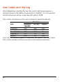
User Codes and the Log
When displaying or printing the log, the control unit shows users as a
number (shown in the table of log events as “####”). You can see this
number when you set up a new user with option 2-4.
The control unit reserves some user numbers for special purposes:
User
Engineer
Manager
Downloader
Keypad PA
System
M50/600/
750/800
000
001
050
051
052
Number
M1000
000
001
100
101
102
M2000
000
001
251
252
253
If you are not sure what type of control unit your system has, don’t worry.
The control unit will not let you use one of the reserved numbers.
56
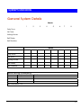
System Records
General System Details
Wards
1
2
3
4
5
6
7
8
Entry Time
Exit Time
Setting Mode
Bell Delay
Bell Duration
Wards
Entry Time
Exit Time
Setting Mode
Bell Delay
Bell Duration
Remote Servicing (Downloading)
Site
Telephone No
Details
1
2
3
User Authorised Y/N
57
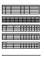
Ward Groups
Group Name
Wards
Group Name
1
2
3
4
5
Shunt Groups
Group Zone 1
Time Switch 1
Timer
On at
Wards
6
7
8
9
0
Zone 2
Zone 3
Zone 4
Zone 5
Zone 6
Zone 7
Zone 8
Off at
Mon Tue
Wed Thu
Fri
Sat
Sun
Off at
Mon Tue
Wed Thu
Fri
Sat
Sun
Off at
Mon Tue
Wed Thu
Fri
Sat
Sun
1
2
3
Time Switch 2
Timer
On at
1
2
3
Time Switch 3
Timer
On at
1
2
3
58
Auto-Set Timer 1
Timer
Set at
Unset at
Mon Tue
Wed Thu
Fri
Sat
Sun
Unset at
Mon Tue
Wed Thu
Fri
Sat
Sun
Unset at
Mon Tue
Wed Thu
Fri
Sat
Sun
Off at
Mon Tue
Wed Thu
Fri
Sat
Sun
1
2
3
Set Wards:
Auto-Set Timer 2
Timer
Set at
1
2
3
Set Wards:
Auto-Set Timer 3
Timer
Set at
1
2
3
Set Wards:
Code Lock Timer
Timer
On at
1
2
3
Users:
59
User Details
No.
1
60
Name
Type
Manager
Wards
Auto-set
Auto-Unset
Zone Details
Zone No. Location
Chime Y/N Wards
61
Service Record
Date
62
Engineer
Action
Installer Information
Installation Engineer:
Installation Company:
Address:
Telephone Number:
Reset Message:
Alarm Receiving Centre:
Telephone Number:
Remote Reset Message:
63
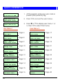
Quick Reference
BANNER TEXT
17:30 Sun 01 JAN
1. At the keypad, enter your user code or
present your proximity tag.
0=Set Selection
[Ent]=User Level
2. Press [ to access the user menus.
User Level 1
Press [Ent]or[2]
3. Press | or ¬ to display user menu 1 or
2, then [ to select that menu.
User Menu 1
User Menu 2
User 1 Menu 1
Test Menu
Page 4
User 2 Menu 1
View Zones
Page 17
User 1 Menu 2
Omit Zones
Page 8
User 2 Menu 2
Time and Date
Page 18
User 1 Menu 3
Shunt 24hr Zones
Page 9
User 2 Menu 3
Edit Shunts
Page 19
User 1 Menu 4
Change Code
Page 10
User 2 Menu 4
Edit Codes
Page 21
User 1 Menu 5
Enable Chime
Page 11
User 2 Menu 5
Edit Chime Zones
Page 32
User 1 Menu 6
Volume Control
Page 12
User 2 Menu 6
Communications
Page 33
User 1 Menu 7
Customise Text
Page 13
User 2 Menu 7
Configure Wards
Page 35
User 1 Menu 8
Silent Set Wards
Page 14
User 2 Menu 8
Edit Groups
Page 36
User 1 Menu 9
Engineer Access
Page 15
User 2 Menu 9
Log
Page 37
User 1 Menu 0
Set/Unset Menu
Page 16
User 2 Menu 0
Timers
Page 40
64
NOTES
65
11751729