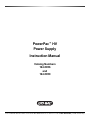
1
PowerPac™ HV
Power Supply
Instruction Manual
Catalog Numbers
164-5056
and
164-5059
For Technical Service Call Your Local Bio-Rad Office or in the U.S. Call 1-800-4BIORAD (1-800-424-6723)
Technical Support
For Technical Support contact your local Bio-Rad office. In the US call 1-800-4BIORAD
(1-800-424-6723).
Please have the following information available.
Model number: Located on the sticker on the bottom of the unit.
Serial number: Located on the sticker on the bottom of the unit.
Firmware version: The PowerPac HV displays the software version momentarily after
switching the power ON.
State clearly the error code, error message or anomaly, and the conditions that originated
the problem, including run parameters (volts, amperes and watts) as well as electrophoresis
cell and buffer system.
Calibration and Service agreements are available through Technical Support.
© Copyright 2005 Bio-Rad Laboratories, Inc. All rights reserved.
Palm is a trademark of Palm Source, Inc.
Windows 2000 and Windows XP are trademarks of Microsoft Corp.
a
!
!
Safety
!
Read this page before proceeding.
Bio-Rad PowerPac power supplies are designed and certified to meet EN 61010* safety
standards. Certified products are safe to use when operated in accordance with the
instruction manual. This safety certification does not extend to electrophoresis cells or
accessories that are not EN 61010 certified, even when connected to this power supply.
This instrument should not be modified or altered in any way. Alteration of this instrument will
void the manufacturer's warranty, void the EN 61010 certification, and create a potential
safety hazard for the user.
This product is intended for laboratory use only. It is not intended for use in residential or
commercial environments. Bio-Rad is not responsible for any injury or damage caused by the
use of this instrument for purposes other than those for which it is intended, or by modifications
of the instrument not performed by Bio-Rad or an authorized agent.
PowerPac power supplies use high output voltages that are electrically grounded to minimize
the risk of electrical shock. PowerPac power supplies have passed tests for operation at
temperatures between 0° and 40°C, with relative humidity between 0 and 95%,
non-condensing. Operating the power supply outside these conditions is not recommended
by Bio-Rad and will void the warranty.
The following guidelines should be observed and followed.
1. Do not block the fan vents at the rear of the unit. There must be at least 6 cm clearance
around the power supply during operation.
2. The power supply must be kept away from wet surfaces. Avoid splashing or leaking
solutions into the power supply.
3. Always connect the power supply to a grounded AC outlet. An acceptable power cord
is provided with the instrument.
4. Bio-Rad electrophoresis cells have molded two-prong plugs that are inserted into the
power supply's high voltage output jacks. These plugs have been EN 61010 certified
for safety compliance for use with PowerPac power supplies. Use of other plugs or
banana jacks is done at the user's own risk and is not recommended by Bio-Rad.
When inserting and removing the molded two-prong plug, always grasp the plug by the
molded support at the rear of the plug. Do not grasp the individual prong ends.
5. Do not operate the power supply in extreme humidity (>95%) or where condensation
can short the internal electrical circuits of the power supply.
6. When taking the power supply from room temperature into a cold room, the unit can be
operated immediately. When removing the power supply from a cold room, the unit
must be at room temperature for a minimum of 2 hours before operation.
7. Never connect a high-voltage output lead to earth ground. This cancels the floating
ground of the power supply and exposes the user to potentially lethal high voltages.
!
! Caution
!
This product conforms to the Class A Standards for electromagnetic emissions, intended
for laboratory equipment applications. It is possible that emissions from this product may
interfere with some sensitive appliances when placed near or on the same circuit. The user
should be aware of this potential and take appropriate measures to avoid interference.
*The EN 61010 is an internationally accepted electrical safety standard for laboratory instruments.
i
Table of Contents
Page
Section 1
Introduction ................................................................................1
1.1
1.2
1.3
Overview.................................................................................................1
Features .................................................................................................2
Unpacking...............................................................................................3
Section 2
Control Panel ..............................................................................4
Section 3
Product Setup.............................................................................5
3.1
3.2
3.3
Power Supply Connections .....................................................................5
Preferences Setup ..................................................................................6
Explanation of Safety Features and Setup Options .................................7
3.3.1
Pfd: Power Failure Detection .....................................................7
3.3.2
RRCd: Rapid Resistance Change Detection..............................8
3.3.3
NLd: No Load Detection ............................................................8
Section 4
Operation ..................................................................................10
4.1
Manual Mode ........................................................................................11
4.1.1
Create, Edit and Run in Manual Mode .....................................12
Basic Methods Mode ............................................................................14
4.2.1
Create, Edit and Run a Basic Method ......................................15
IEF Methods Mode................................................................................18
4.3.1
Create, Edit and Run an IEF Method .......................................19
Temperature Mode ...............................................................................22
4.4.1
Create, Edit and Run in Temperature Method..........................23
Edit a Paused Run ................................................................................25
4.5.1
Editing a Paused Run ..............................................................26
4.2
4.3
4.4
4.5
Section 5
Data Transfer Using the Infrared (IR) Port...............................27
5.1
5.2
Overview...............................................................................................27
System Requirements...........................................................................28
Section 6
Maintenance and Troubleshooting ..........................................28
6.1
Maintenance .........................................................................................28
6.1.1
Replacing a Fuse.....................................................................28
6.1.2
Replacement Parts ..................................................................29
Troubleshooting ....................................................................................29
Error Messages ....................................................................................30
6.2
6.3
Appendix A Technical Specifications ..........................................................33
Appendix B Warranty and Ordering Information.........................................34
List of Figures
Figure 1.
Figure 2.
Figure 3.
Figure 4.
Figure 5.
Figure 6.
Figure 7.
Figure 8.
Figure 9.
Figure 10.
Figure 11.
Figure 12.
Figure 13.
Figure 14.
Front View................................................................................................1
Rear View ................................................................................................1
Front Panel with Legs ..............................................................................2
Front Panel ..............................................................................................4
Power Leads Connected Correctly ..........................................................5
Power Leads Connected Incorrectly ........................................................5
Menu Overview for Manual Operation ....................................................11
Menu Overview for Basic Methods Mode ..............................................14
Menu Overview for IEF Methods ............................................................18
Menu Overview for Temperature Mode ..................................................22
Menu Overview for Editing a Pause Run ................................................25
IR Port Location ....................................................................................27
Transfer of Methods and Run Data Files ................................................27
Location of Fuse ....................................................................................29
iv
PowerPac HV – Instruction Manual
Section 1
Introduction
1.1 Overview
The PowerPac HV power supply is designed to provide constant voltage, current, or power
for a wide range of electrophoresis applications, including IEF and SDS PAGE. It also
provides temperature control for DNA sequencing with the Sequi-gen cell.
The PowerPac HV operates at the constant value specified by the user. If a non-constant
parameter becomes limiting, the PowerPac HV will automatically cross over and continue
operating at the limiting parameter.
Output range
Voltage
Current
Power
Output jacks
20–5,000 Volts (V)
Adjustable in 0.1 V increments from 20.0 to 99.9 V
Adjustable in 1 V increments from 100 to 5000 V
0.01–500 mA.
Adjustable in 0.01 mA steps from 0.01 to 9.99 mA
Adjustable in 1 mA increments from 10 to 500 mA
0.1–400 W
Adjustable in 0.1 Watt increments from 0.1 to 9.9 W
Adjustable in 1 W increments from 10 to 400 W
Four sets of output jacks are provided to facilitate connection of up
to four identical electrophoresis cells simultaneously
1
2 abc
4 ghi
5 jkl
6 mno
7 pqrs
8 tuv
9 wxyz
EDIT
0
3 def
CE
FRONT PANEL
OUTPUT JACKS
Fig. 1. Front view.
Fig. 2. Rear view.
1
PowerPac HV – Instruction Manual
1.2 Features
The PowerPac HV has the following features:
•
Constant voltage, voltage ramping, constant current or constant power operation with
automatic crossover and temperature control mode
•
Backlit LCD screen
•
Continuous display of all parameters
•
Continuous, timed and Volthours run control
•
Nine (9) programmed runs, each containing up to nine steps
•
Pause mode for editing running parameters
•
Automatic detection of no-load, short circuit, rapid resistance change, ground leak, fan
failure and system overheating
•
Automatic completion (if desired) of a run interrupted by AC power failure
•
Stackable case with adjustable viewing angle (Figure 3)
•
Adjustable LCD display contrast
•
EN 61010 international safety certification
•
Input power 100–120/220–240 VAC, 50/60 Hz, auto-switching
•
Four output terminals
1
2 abc
4 ghi
5 jkl
6 mno
7 pqrs
8 tuv
9 wxyz
EDIT
0
LEGS
(LOWERED POSITION)
Fig. 3. Front panel with legs.
2
3 def
CE
PowerPac HV – Instruction Manual
1.3 Unpacking
When the power supply is received, carefully inspect the container for any damage which
may have occurred in shipping. Severe damage to the container may indicate damage to the
power supply itself. If you suspect damage to the unit, immediately file a claim with the carrier
in accordance with their instructions before contacting Bio-Rad Laboratories.
Unpack the PowerPac HV. Remove the plastic film from the translucent green top case.
The plastic film may leave a residue. If so, clean with a soft, damp cloth.
Contents include:
•
•
•
•
•
PowerPac HV power supply
Power cord
Instruction manual
Warranty card
Declaration of conformity
If any part is missing or damaged, contact Bio-Rad Laboratories immediately.
3
PowerPac HV – Instruction Manual
Section 2
Control Panel
1
2 abc
3 def
RUN/PAUSE KEY
4 ghi
5 jkl
6 mno
STOP/HOME KEY
7 pqrs
8 tuv
9 wxyz
EDIT
0
CE
ALPHANUMERIC
KEYPAD
CLEAR ENTRY KEY
SETUP KEY
IR PORT
FUNCTION KEYS
EDIT KEY
CURSOR KEYS
Fig. 4. Front Panel.
Key
Run/Pause
Description
Starts or pauses a run. When paused, the run parameters for the
current or subsequent step(s) may be edited. The modified method may
be stored to permanent memory by pressing SAVE at the end of the run.
Stop/Home
Terminates the run in progress and displays the final run parameters, or
if no run is active, changes the display to the Home screen.
Note: If a method has been edited during a run, SAVE must be pressed
at the end of the run to save the changes.
Setup
The SETUP menu allows the operator to set preferences. Press Setup
key again to exit the SETUP menu.
Preferences include: power failure detection, rapid resistance change
detection, no load detection, IR Data acquisition, contrast, key sound,
temperature probe check date and time settings (see Section 3.2).
EDIT Key
EDIT
Toggles soft key assignments between those used to set the run mode
(constant voltage, constant current, or constant power), run
limits (voltage, current, or power) and time mode (hours, volt-hours, or
untimed).
Up & down
arrows and
decimal point
Used to scroll through method list or method protocol. An asterisk (*) is
used to identify the selected method or step. The up arrow is used to
enter decimal point during parameter programming.
CE
Clears alphanumeric characters from a parameter value or method name.
It can be considered the backspace key.
CE
Alphanumeric
keypad
Function or
Soft keys
4
Used to enter parameter values and method names. When method
names are entered, the manner in which keys are pressed determines
the characters entered and their placement. Rapid repetitive strokes on a
single key, toggles the character displayed at the cursor position. The
cursor position advances each time a different key is pressed or when
there is a pause between strokes of a single key. The “0” key accesses
the “pH” and hyphen “–” sequence.
The function of the three soft keys is indicated by the legend displayed
directly above the key. This will vary with the menu tree.
PowerPac HV – Instruction Manual
Section 3
Product Setup
3.1 Power Supply Connections
This section describes how the PowerPac HV power supply is connected to an electrophoresis
cell or cells.
Step
1.
Procedure
Connect the
power cord
Description
Connect one end of the included power cord to the
rear of the instrument. Connect the other end to a
compatible power source.
2.
Connect cells
Insert power leads into one of the output terminals
located on the front of the power supply (shown to
the left). Note that the
symbol indicates high
voltages and that the power leads must be inserted
perpendicular to the curve of the case (see below).
Fig. 5. Power Lead Connected Correctly
Fig. 6. Power Leads Connected Incorrectly
5
PowerPac HV – Instruction Manual
Step
Procedure
Description
3.
Turn power on
Use the switch located on the right side of the power
supply to power on. Initially, the unit will display the
firmware version and serial number for a few seconds,
then go to the Home screen. The Home screen soft
keys are used to select operation modes; Manual
(Section 4.1), IEF Methods (Section 4.3), and Basic
Methods (Section 4.2).
To access the Temperature mode insert the leads
of the thermocouple probe into the connections at
the rear of the power supply (Section 4.4).
3.2 Preferences Setup
The PowerPac HV offers customizing options to enable and disable safety features and
infrared (IR) port, as well as LCD display contrast adjustment, key sound, and set local time
and date.
Step
1.
Procedure
Open the Setup editor
Description
Press SETUP to start the Setup editor. SETUP can
be pressed from any screen except the run screen.
2.
Select the SETUP
preference
Scroll through the SETUP preferences using the
arrow keys. The asterisk indicates the selected
preference.
The soft key CHANGE toggles between the different
options or settings for the selected preference.
The RESET soft key allows the user to change all
the preference settings to the default values, except
for time and date.
3.
6
EXIT
Pressing the EXIT soft key or the SETUP key
accepts any changes made, and exits the SETUP
menu.
PowerPac HV – Instruction Manual
3.3 Explanation of Safety Features and Setup Options
3.3.1 Pfd: Power Failure Detection
Preference
PFd
Power Failure Detection
SETUP
* PFd
RRCd
NLd
CHANGE
1.
EXIT
OFF
ON
ON
RESET
Options
OFF
(Default)
NEXT RUN
ON
Description
OFF: Turns power failure detection OFF.
In this mode, the run is terminated if a
power failure occurs.
NEXT RUN: Turns power failure
detection on for a single run. PFd will
show on the upper right corner of the
Run screen.
ON: Turns power failure detection mode
on in all runs. If there is a power failure in
this mode, then the run will resume when
the power is restored. PFd will show on
the upper right corner of the Run screen.
Warning: Turning the power supply off
(Stopping a run in progress with PFd
enabled, is regarded as a power failure.)
The "interrupted" run will resume
automatically when the power is
restored.
If a power failure occurred during the run with
PFd enabled, the MORE soft key is displayed
on the Run Completed screen.
Press MORE to display details about the most
recent power outage and when power was
restored.
Press RERUN to restart the run.
Press BACK to return to the Run Completed
screen. Press EXIT to go to the Method screen.
2.
Displayed if PFd = OFF
This error screen is displayed if a run has
terminated due to a power failure.
Press RESET to return to the Home screen.
7
PowerPac HV – Instruction Manual
3.3.2 RRCD: Rapid Resistance Change Detection
Preference
RRCd
Rapid Resistance Change
detection
Options
ON
(Default)
OFF
Description
ON: Detection of a sudden resistance
change greater than 20% will cause an
alarm to sound, the run to pause, and
error message code 09 to be displayed.
(See Section 6.3)
OFF: All resistance changes are ignored
and the run does not stop. When running
in this mode, the
symbol is displayed
on the run screen as a reminder that this
safety feature has been turned off.
Note: Completion of certain
electrophoresis applications using cells,
such as the DCode™ and Rotofor®, may
require RRCd to be turned off.
3.3.3 Nld: No Load Detection
NLd
No Load Detection
ON
(Default)
OFF
IRDA Port
Infrared (IR) port
communication
ON
(Default)
OFF
Display CONTRAST
HI
(Default)
ME
LO
8
ON: A drop in the current below a set
threshold will cause the run to pause,
an alarm to sound and the error code 01
to be displayed (see Section 6.3). For
example, if an electrophoresis cell is not
connected or the current is too low (less
than 0.02mA for Manual or Basic
Methods and 0.005mA for IEF methods).
OFF: All load changes are ignored and
the run does not stop. When running in
this mode, the
symbol is displayed
on the Run screen as a reminder that
this safety feature has been turned off.
Some IEF applications may run at a
current lower than 0.005 mA, therefore,
the No Load detection may need to be
disabled in order to complete the run.
ON: Enables IR port communication.
OFF: Disables IR port communication to
prevent communication interference with
other nearby IR devices, e.g., another
PowerPac power supply
Adjusts the display contrast to
accommodate different illumination
conditions.
HI
=
High contrast
ME
=
Medium contrast
LO
=
Low contrast
KEY CHIRP
IRDA
CONTRAST
* KEY CHIRP
CHANGE
EXIT
ON
(Default)
OFF
PowerPac HV – Instruction Manual
Activates the audible signal for keystroke.
ON
HI
ON
RESET
DATE
MM/DD/YY
This is the only format available.
Press the change soft key then enter the
correct date using the alphanumeric
keypad.
HH:mm
24 hr format. Factory setting is Pacific
Standard time
SETUP
KEY CHIRP
ON
DATE
12/07/04
* TIME
16:38 HRS
CHANGE
EXIT
RESET
TIME
SETUP
KEY CHIRP
ON
DATE
12/07/04
* TIME
16:38 HRS
CHANGE
EXIT
RESET
TEMP PROBE CK
Temperature Probe Check
Press the change soft key then enter the
correct time using the alphanumeric
keypad.
ON
(Default)
OFF
This preference is only available when
the temperature probe is connected.
ON: The run is paused and error code
18 is displayed in case of failure. A failure
occurs when the temperature remains
5°C less than the set temperature for
more than 15 minutes. This can be caused
by a detached temperature probe or an
insufficient power setting.
OFF: Run will continue regardless the
temperature.
9
PowerPac HV – Instruction Manual
Section 4
Operation
The PowerPac HV has four operation modes:
1. Manual: Single-step run, not stored in memory. (see Section 4.1)
2. Basic Methods: Nine (9) methods with up to nine steps can be stored. (see Section 4.2)
3. IEF Methods: Nine (9) methods with up to nine (9) steps can be stored. This mode
allows direct programming for high-voltage, low-current applications; also allows voltage
ramping and run delay. (see Section 4.3)
4. Temperature: Incorporates temperature sensing as a limiting parameter and adjusts
power output in order to control temperature in the electrophoresis cell. (see Section 4.4)
10
PowerPac HV – Instruction Manual
4.1 Manual Mode
Manual mode allows the user to program and start a single-step method with a minimum
number of keystrokes. This single-step method is not stored in permanent memory.
This section describes how to program and perform a run in Manual mode.
SELECT MODE
MANUAL
METHODS
IEF BASIC
EDIT CONSTANT
100 V
500 mA
400 W
TIME:UNTIMED____________
CONSTV CONSTA CONSTW
EDIT
EDIT LIMITS
100 V
500 mA
400W
TIME: UNTIMED _______
CONSTV LIMITA LIMITW
EDIT
S1/1 EDIT TIME
200 V
500 mA
500W
TIME: UNTIMED____________
HRS
VHRS
UNTIMED
RUN
100 V
52 mA
5.2 W
00:00/00:30 00:OO HRS____
PAUSE
Fig. 7. Menu Overview for Manual Mode.
11
PowerPac HV – Instruction Manual
4.1.1 Create, Edit and Run in Manual Mode
Step
Procedure
Description
1.
Set up the power
supply
Refer to Section 3 for instrument setup.
2.
Select the mode
From the Home screen, press the MANUAL soft
key to perform a single-step run in Manual mode.
SELECT MODE
MANUAL
3.
When in doubt, press EDIT to toggle between
screens without losing entered values.
METHODS
BASIC
IEF
Select a constant
parameter
EDIT CONSTANT
500 mA
400 W
TIME: UNTIMED
CONSTV CONSTA CONSTW
Use the soft keys to select which parameter will be
constant and the alphanumeric keypad to enter its
value.
CONSTV: Operates with constant voltage.
CONSTA: Operates with constant current.
CONSTW: Operates with constant power.
Press EDIT to enter the value and to proceed to the
EDIT LIMITS screen. (Step 4)
4.
Enter limits for the
nonconstant parameters
EDIT LIMITS
500 mA
400 W
TIME: UNTIMED
CONSTV LIMITA LIMITW
If the run will be untimed at the currently displayed
constant value and limits (shown to the right of the
constant parameter), go to step 6.
Use the soft keys to select a nonconstant
parameter and the keypad to enter its value. Press
EDIT key twice to go back to step 3.
CONSTV, A or W: Press CONST soft key to change
the parameter value.
LIMITV, A, or W: Press LIMIT soft key to change
the parameter value.
Press EDIT to enter the values and to proceed to
the EDIT TIME screen.
5.
Select the time mode.
If the run will be untimed at the currently displayed
constant value and limits (shown to the right of the
constant parameter), go to step 6.
Use the soft keys to select the time mode and the
keypad to enter the run time.
HRS:
Run time is in units of hours
VHOURS: Run time is in units of volthours.
Untimed: Run is continuous
The selected mode is shown above the line next to
time. Use the soft keys to select and the keypad to
enter HRS AND VHOURS.
12
PowerPac HV – Instruction Manual
Step
Procedure
Description
6.
Start the run
Press
to start a run. A run may be started from
any screen of the EDIT loop as long as a valid
constant parameter value has been entered.
7.
Monitor the run
The run screen displays the elapsed time versus the
programmed time (timed runs), elapsed time
(untimed run), voltage, current and power values.
8.
Pause
Press the soft key PAUSE or the
the run in progress.
key to pause
The run parameters and user preferences may be
edited during pause.
Press EDIT to change run parameters
Press SETUP to change user preferences.
Press the soft key CONTINUE or the
resume the run.
key to
13
PowerPac HV – Instruction Manual
4.2 Basic Methods Mode
Basic Methods Mode is used to create, run and store basic methods. It has the same
programming options (edit loop) as the Manual mode. The method list stores up to nine
methods, with up to nine steps each. These methods may also be transferred to or from a
PDA, through the PowerPac IR port as described in Section 5.
SELECT MODE
MANUAL
METHODS
IEF BASIC
METHOD LIST
* SDS PAGE
IEF
…EMPTY 3…
____________________________
OPEN DELETE
NEW
METHOD: SDS PAGE
* S1 10V 00:30 HRS
S2 200V UNTIMED
S3 (EMPTY)
________________________
METHODS DELETE (SAVE)
METHOD: UNTITLED
* S1 (EMPTY)
NAME: xxxxx
__________________________
METHODS
EDIT
EDIT
S1/1 EDIT CONSTANT
200 V
500 mA
400 W
TIME: UNTIMED___________
CONSTV CONST CONSTW
EDIT
S1/1 EDIT LIMITS
200 V
500 mA
400W
TIME: UNTIMED _______
CONSTV LIMITA LIMITW
EDIT
Enter
Limits
S1/1 EDIT TIME
EDIT
200 V
2500 mA
500W
TIME: UNTIMED _______
HRS VHRS
UNTIMED
RUN: S2/4
216 V
00:02/00:30
Fig. 9. Menu Overview for Basic Methods Mode.
14
235 mA
50 W
01:32HRS
PAUSE
____________________
CANCEL
OK
PowerPac HV – Instruction Manual
4.2.2 Create, Edit and Run a Basic Method
This section describes how to create, open, modify and run Basic Methods.
Step
Procedure
Description
1.
Set up the power supply
Refer to Section 3 for instrument setup.
2.
Select the operation
mode
At the Home Screen:
Press the BASIC METHODS soft key to display the
Method List screen.
SELECT MODE
MANUAL
3.
METHODS
BASIC
IEF
Basic Method List
Options:
METHOD LIST
* SDS-PAGE
... EMPTY 2 ...
... EMPTY 3 ...
OPEN
DELETE
NEW
•
Press NEW to create a new method (go to step 4).
•
OPEN a stored method. An asterisk indicates the
selected method. Select a stored method using
the arrow scroll keys and press the OPEN soft
key. Go to step 4 to edit method, otherwise go to
step 10 to start the run.
•
DELETE a stored method. Select a stored
method using the arrow scroll keys and press
the DELETE Soft key. An asterisk indicates the
selected method.
Note: If the method list is full (nine methods), a
method needs to be deleted before a new method
can be added to the list.
4.
Name the Method
Press the up arrow key to select the method
name field.
METHOD: NAME
*
S1
Use the CE button to clear the name field and the
alphanumeric keypad to enter a method name.
Refer to Section 2 for help using the keypad.
(EMPTY)
Press OK to accept the new name and return to
the METHOD SCREEN with new or edited run
name.
METHODS
EDIT NAME: UNTITLED
S1
CANCEL
Press CANCEL to abort naming the method and
return to the METHOD SCREEN.
(EMPTY)
OK
15
PowerPac HV – Instruction Manual
Step
Procedure
Description
5.
Method steps
Press EDIT to enter the edit loop.
New method
• Press the up and down arrows to select an
existing step or select the (EMPTY) step to add a
new step
METHOD: NAME
*
S1
(EMPTY)
• Press EDIT again to enter the edit loop for the
selected step
METHODS
METHOD: NAME
Existing
method
S1
100V 00:30 HRS
*
S2
METHODS
6.
(EMPTY)
DELETE
SAVE
Set the constant
parameter for the
current step
Use the soft keys to select the constant parameter
and the keypad to enter its value. Note that the
non-constant values are listed on the right side of
the screen and the time mode at the bottom.
The S#/# indicates which step is being modified. In
this case, S1/1 means editing step 1 of 1.
CONSTV:
Operates with constant voltage.
CONSTA:
Operates with constant current.
CONSTW: Operates with constant power.
Press EDIT to continue.
7.
Enter limits for the
non-constant
parameters for the
current step
S1/1 EDIT LIMITS
500 mA
400 W
TIME: UNTIMED
CONSTV LIMITA LIMITW
Use the soft keys to select a parameter and the
alphanumerical keypad to enter its value.
The soft keys CONST_ or LIMIT_ change according
to the constant parameter selected in the EDIT
CONSTANT screen.
Note: The constant parameter value can be
changed at this point. Press its soft key and enter a
new value.
LIMITV
Change the voltage limit (or constant)
(CONSTV): value.
LIMITA
Change the current limit (or constant)
(CONSTA): value.
LIMITW
Change the power limit (or constant)
(CONSTW): value.
Press EDIT to continue.
16
PowerPac HV – Instruction Manual
Step
Procedure
Description
8.
Select the time mode
Use the soft keys to select a time mode and the
alphanumeric keypad to enter the run time.
S1/1 EDIT TIME
500 mA
400 W
TIME: UNTIMED
HRS
VHOURS UNTIMED
HRS:
Run time is in units of hours.
VHOURS:
Run time is in units of volt-hours.
UNTIMED: Run is continuous.
Note: Steps programmed after an untimed step are
ignored.
Press EDIT to return to the Method Screen.
9.
Add a new step or
save the method
To program additional steps press the down arrow
key to select the empty step and repeat Steps 5–8.
If the method will not be saved, go directly to Step 10.
Press SAVE and then go to Step 10.
Press DELETE to delete a selected step.
Press the METHOD soft key to return to the Method
List.
10.
Start the run
Press
to start a run.
11.
Monitor the run
The RUN screen is used to monitor run parameters
or to pause a run. The current step, Volts, mA and
Watts values, elapsed time versus the programmed
time, and total elapsed time are displayed on the
RUN screen. The method step is also indicated.
This run is executing Step 1 of 2.
The run may be paused by pressing the PAUSE
soft key or the
key.
To edit the run parameters during PAUSE see
Section 4.5. Edits made during the run may be
saved, if the SAVE soft key is pressed at the end of
the run. Otherwise the method will remain as
originally created.
To terminate the run, press the
12.
key.
The Run Completed or Run Terminated screen is
displayed at the end of a run. Press RERUN to
repeat the run or EXIT to display the method step
list.
17
PowerPac HV – Instruction Manual
4.3 IEF Methods Mode
The IEF Method mode is used to create, run and store Isoelectric focusing (IEF) methods.
The method list stores up to nine methods, with up to nine steps each. Special programming
options such as voltage ramping and run delay in the first step, allow better control during
IEF separations. These methods may also be transferred to or from a PDA, through the
PowerPac IR port as described in Section 5.
SELECT MODE
MANUAL
METHODS
IEF BASIC
IEF METHOD LIST
* pH 3-10
IEF
***EMPTY…
____________________________________
OPEN
DELETE
NEW
METHOD: PH 3-10
*S1 100V Ê 00:30 HRS
S2 800V Ê 05:30 HRS
S3 …EMPTY….________
METHOD:UNTITLED
* S1 ****EMPTY****
____________________
METHOD
METHOD DELETE (SAVE)
EDIT
EDIT
S1/1 VOLT PROFILE
2000 V V-SLOPE
LINEAR
TIME: 0:00 HRS
V-MAX V-SLOPE (DELAY)
EDIT
S1/1 EDIT LIMITS
2000 V 0.00 mA
0.1 W
TIME: 0:00 HRS
V-MAX LIMITA LIMITW
EDIT
S1/1 EDIT TIME
EDIT
2000 V 0.10 mA
0.1 W
TIME: 00:30 HRS___________
HRS
VHRS
Fig. 9. Menu Overview for IEF Methods
18
NAME: xxxxx
__________________
OK
CANCEL
PowerPac HV – Instruction Manual
4.3.1 Create, Edit, and Run an IEF Method
This section describes how to create and edit methods.
Step
Procedure
Description
1.
Set up the power supply
Refer to Section 3 for instrument setup.
2.
Select the operation
mode
At the Home screen, press the IEF METHODS soft
key to display the IEF Method List screen.
SELECT MODE
MANUAL
3.
METHODS
BASIC
IEF
IEF Method List
Options:
• Press NEW to create a new method (go to step 4).
New method
• OPEN a stored method. Select a stored method
using the arrow scroll keys, an asterisk indicates
the selected method, and press the OPEN soft
key. Go to step 4 to edit method, otherwise go to
step 11 to start the run.
• DELETE a stored method. An asterisk indicates
the selected method. Select a stored method
using the arrow scroll keys and press the
DELETE Soft key.
Existing method
IEF METHOD LIST
* pH-3-10
... EMPTY 2 ...
... EMPTY 3 ...
OPEN
DELETE
NEW
Note: If the method list is full (nine methods), a
method must be deleted before a new method
can be added to the list.
METHOD: pH-3-10
S1 500V
00:05 HRS
S2 5000V
05:00 HRS
*S3 500V
00:30 HRS
METHODS DELETE
19
PowerPac HV – Instruction Manual
Step
Procedure
Description
4.
Method name
Name a method.
• Press the up arrow key to select the method
name field.
• Use the CE button to clear the name field and the
alphanumeric keypad to enter a method name.
Refer to Section 2 for help using the keypad.
• Press OK to accept the new name and return to
the METHOD SCREEN with new or edited run
name.
Press CANCEL to abort naming the method and
return to the METHOD SCREEN.
5.
Method steps
Enter the Step Edit sequence.
METHOD: pH-3-10
S1 500V
00:05 HRS
S2 5000V
05:00 HRS
*S3 500V
00:30 HRS
METHODS DELETE
6.
Set the Voltage profile
S1/1 VOLT PROFILE
V-SLOPE
RAPID
TIME: 01:00 HRS
V-MAX V-SLOPE DELAY
7.
Set time delay
S1/1 EDIT TIME DELAY
• Press the up and down arrows to select an
existing step or select the (EMPTY) step to add a
new step.
• Press EDIT to enter the edit loop for the selected
step.
• Use the V-MAX soft key to enter the maximum
voltage value with the keypad for the current step
• Use the V-SLOPE soft key to select the voltage
ramping (slow, linear or rapid).
Press EDIT to proceed to step 8, Edit Limits.
Use the DELAY soft key, available only in the
first step of a method, to program a run delay. No
voltage is applied during the duration of the step.
• Enter the time delay and press OK to accept, and
go to the method steps screen (step 5) to edit
additional steps.
• CANCEL to return to the Volt profile screen.
DELAY: 00:00 HRS
CANCEL
20
OK
PowerPac HV – Instruction Manual
Step
Procedure
Description
8.
Enter parameter limits
Current or power limits must be set according to
application instructions to prevent overheating of the
IEF device .
Use the soft keys to select a limit parameter and the
keypad to enter its value. Once the limit mA or W
has been entered, the complementary value will be
automatically calculated by pressing the LIMIT soft
key or EDIT key.
V-MAX:
Change the voltage limit value.
LIMITA:
Set the current limit value.
LIMITW:
Set the power limit value.
Press EDIT to continue.
9.
Select the time mode
Use the soft keys to select a time mode and the
keypad to enter the run time.
HRS:
Run time is in units of hours.
VHOURS: Run time is in units of volt-hours.
Press EDIT to continue.
10.
Add a new step or save
the method
To program additional steps press the down arrow
key to select the empty step and repeat steps 5–9.
If the method will not be saved, start the run. Press
SAVE and then start the run.
Press DELETE to delete a selected step.
Press the METHOD softkey to return to the Method
List.
11.
Start the run
Press
to start a run.
12.
Monitor the run
The run screen is used to monitor run parameters
or to pause a run. The current step, voltage ramping,
mA and W, elapsed time versus the programmed
time, and total elapsed time are displayed on the
run screen. The method step is also indicated. This
run is executing Step 1 of 2.
The run may be paused by pressing the PAUSE
soft key or the
key.
To edit the run parameters during PAUSE, see
Section 4.5. Edits made during the run can be
saved by pressing the SAVE soft key at the end of
the run.
To terminate the run press the
key.
21
PowerPac HV – Instruction Manual
Step
Procedure
Description
13.
The Run Completed or Run Terminated screen is
displayed at the end of a run. Press RERUN to
repeat the run or EXIT to display the method step
list.
4.4 Temperature Mode
The Temperature operation mode is used to run an electrophoresis apparatus at constant
temperature. Temperature control is very useful to perform DNA sequencing and Single
Stranded Conformational Polymorphism (SSCP) analysis in the Sequi-Gen® GT system. The
temperature limit may be set from 30 to 90°C; actual temperature will be controlled from room
temperature to 90°C.
The PowerPac HV monitors the temperature of the electrophoresis cell through the
temperature probe (catalog #165-5058) attached to the wall of the cell. The temperature of
the cell is controlled by regulating the power output (in W) once the cell temperature is
within 2°C of the set temperature.
Connect Temperature
Probe to rear of
instrument
TEMPERATURE MODE
TO EXIT TEMP MODE
REMOVE THE PROBE
CONTINUE
SET TEMPERATURE LIMIT
50 °C
______________________
EDIT
EDIT PARAMETERS
55 W
5000 V
500 mA
TIME: UNTIMED
50°C _
LIMITV LIMITA CONSTW
EDIT
EDIT TIME
55 W
5000V
500 mA
TIME: UNTIMED
50°C _
HRS
VHRS UNTIMED
EDIT
Fig. 10. Menu Overview for Temperature Mode
22
RUN
216 V
235 mA
50 W
00:02/00:30 01:32HRS_____
PAUSE
PowerPac HV – Instruction Manual
4.4.1 Create, Edit and Run in Temperature Method
Step
Procedure
Description
1.
Set up the power supply
Refer to Section 3 for instrument setup.
2.
Connect temperature
probe to the back of
the PowerPac HV
The Temperature mode may be accessed from any
screen, except for the run screen, by connecting the
probe.
3.
Attach probe to the
electrophoresis cell
Use the suction cup to attach the temperature probe
to the electrophoresis cell. Make sure the suction
cup remains attached during the run.
4.
TEMPERATURE MODE
TO EXIT TEMP MODE
REMOVE THE PROBE
CONTINUE
5.
Set temperature limit
SET TEMPERATURE LIMIT
The Temperature mode introduction screen appears
automatically.
Press the CONTINUE soft key.
Note: See Section 3.3.4 for additional information
on TEMP PROBE options.
Use the alphanumeric keypad to enter the desired
temperature (30°–90°C).
Press the EDIT soft key to continue.
EDIT
6.
Enter parameters
EDIT PARAMETERS
5000 V
500 mA
TIME: UNTIMED
50¡C
LIMITV LIMITA CONSTW
Use the soft keys to select a parameter and the
keypad to enter its value. To change the constant
value, press its soft key and enter a new value.
LIMITV:
Change the voltage limit value.
LIMITA:
Change the current limit value.
CONSTW: Enter the power constant value.
Note: The constant power value entered will never
be exceeded even if the cell fails to reach the set
temperature.
Press EDIT to continue.
23
PowerPac HV – Instruction Manual
Step
Procedure
Description
7.
Select the time mode
EDIT TIME
5000 V
500 mA
TIME: UNTIMED
50¡C
HRS
VHOURS UNTIMED
55 W
Use the soft keys to select a time mode and the
alphanumeric keypad to enter the run time.
HRS:
Run time is in units of hours.
VHOURS: Run time is in units of volt-hours.
UNTIMED: Run is continuous.
8.
Start the run
Press
to start a run.
9.
Monitor the run
The RUN screen is used to monitor run parameters
or to pause a run. The current step, V, voltage
ramping, mA and W, elapsed time versus the
programmed time, and total elapsed time are
displayed on the run screen.
The run may be paused by pressing the PAUSE
soft key or the
key.
To edit the run parameters during PAUSE see step 6.
To Edit preference see Section 3. Edits made during
the run may be saved if SAVE soft key is pressed at
the end of the run. Otherwise the method will remain
as originally created.
To terminate the run, press the
key.
Note: If the temperature reaches 5° over the set
temperature, an alarm will sound intermittently until
the situation is resolved. That is, until the power is
reduced or the temperature of the gel drops. The
alarm sounds similar to the end of run, but repeats.
10.
24
The Run Completed or Run Terminated screen is
displayed at the end of a run. Press RERUN to
repeat the run or EXIT to display the method step
list.
PowerPac HV – Instruction Manual
4.5 Edit a Paused Run
The PowerPac HV permits editing the run parameters during a pause in all operation
methods modes: Manual, Basic, IEF Methods, and Temperature Mode. The edit capability
during Pause is limited to the current and subsequent steps, and follows the same edit
sequence used when programming the original run. If the current step started as untimed it
cannot be changed to hours or volt-hours.
RUN: S2/4
216 V
235 mA
50 W
00:02/00:30 :32HRS____
PAUSE
RUN TERMINATED AT:
02/18/03
16:11:09
216V 235mA 50W
TIME: 1:00 Vh: 00175
RERUN
EXIT
RUN COMPLETED AT:
02/18/03
16:11:09
216V 235mA 50W
TIME: 1:00 Vh: 00175
RERUN
EXIT
RUN PAUSED AT:
02/18/03 16:11:09
216V 235mA 50W
Time: 00:01 Vh: 00011___
EDIT
CONTINUE
EDIT Loop See specific
method section
Fig. 11. Menu Overview for Editing a Paused Method.
25
PowerPac HV – Instruction Manual
4.5.1 Editing a Paused Run
Step
Procedure
Description
1.
Pause the run
Press the PAUSE soft key or
to pause a run
that is in progress. The S#/# indicates this run is
performing Step 1 of 2 steps.
2.
Edit the method
The pause window displays the current run
parameters as well as the date and time that the run
was paused.
RUN PAUSED AT:
05/27/03
12:29:00
100V
53mA
Time:
00:00
Vh:
CONTINUE
5W
00000
EDIT
Press the EDIT soft key or front panel EDIT button
to edit the run parameters. Follow the instructions in
the appropriate section.
• Section 4.1 for Manual run editing
• Section 4.2 for Basic Methods editing
• Section 4.3 for IEF Methods editing
• Section 4.4 for Temperature mode run editing
Use the CONTINUE soft key or
run.
3.
Exit the Run Completed
screen
to resume the
After the run is finished, press EXIT to return to the
method screen to save the edits (step 4).
Press RERUN to restart the run, keeping the run
parameters the same as the last edit.
4.
Save the changes
From the Method screen, press SAVE to save any
changes made during the run.
Note: Pressing SAVE will overwrite the original
method.
26
PowerPac HV – User Manual
Section 5
Data Transfer Using the Infrared (IR) Port and Data
Transfer Software
5.1 Overview
The PowerPac HV is capable of transmitting methods and data through an infrared (IR)
port located on the front of the power supply (Figure 13). This optional PowerPac Data
Transfer Software (DTS)(catalog #164-5067) includes the PowerPac Remote application
for a PDA.
1
2 abc
4 ghi
5 jkl
3 def
6 mno
7 pqrs
8 tuv
9 wxyz
EDIT
0
CE
FRONT PANEL
OUTPUT JACKS
IR port
Fig. 12. IR port location
Methods can be transmitted to and from the PDA. Run data can be transmitted to a personal
computer (PC), either directly from the power supply or through a PDA.
Using the PDA with PowerPac Remote, methods can be created, stored and beamed to
and from the PowerPac HV. The PDA may also be used as the intermediary to store and
transfer data from PowerPac to the PC (Figure 14).
The PC data transfer software function will receive, store and process run data. The PC
data transfer software will not transfer data back to the PDA or PowerPac HV.
PowerPac
Power Supply
Methods
Data
Data
PALM
PDA
PC
Data
Fig. 13. Overview of Data Transfer
27
PowerPac HV – Instruction Manual
5.2 System Requirements
Minimum PC specifications
•
Windows 2000 or Windows XP Operating System
•
400 MHz processor
•
256 MB RAM minimum, 512 MB recommended
•
1,024 x 768 screen resolution, with true-color mode (24 or 32 bits)
•
10 GB hard drive
•
CD-ROM drive
•
Infrared (IR) port or adaptor
Minimum PDA specifications
•
Palm Operating System, Version 4.0
•
8 MB memory
Section 6
Maintenance and Troubleshooting
6.1 Maintenance
The PowerPac HV requires little maintenance to ensure reliable operation. To clean the
case, first unplug the power supply. Use a soft, damp cloth to wipe the outer case.
Keep the PowerPac HV away from liquids. Prevent them from entering the case.
Inspect the power cord regularly. Replace it if the cord is damaged or the prongs are bent
or corroded (catalog #165-9005).
Replace the temperature probe if the cord is damaged or the connectors are bent or
corroded (catalog #165-5058).
6.1.1 Replacing a Fuse
If the power supply is plugged into a working outlet with the power switch ON, and there is
no display, lights nor fan operation, the fuse may need to be replaced.
1. Disconnect the power cord from the electrical outlet.
2. Use a slot head screwdriver to press the tabs on the side of the fuse holder toward
each other. This will release the fuse holder and the fuses. (Figure 15) Inspect the
fuses visually to determine if one or both of the fuses are blown. If a fuse is blown, it will
be discolored or the internal element will be broken.
3. Remove the blown fuse from the holder. Replace it with 8 A, 250 V, 5 x 20 mm, type T,
fuse (catalog #900-8933).
4. Reinsert the fuse holder into position. Press the fuse holder gently until it snaps into
place on both sides.
5. Reconnect the power cord to the outlet. The unit is now ready for use.
28
PowerPac HV – Instruction Manual
FUSE
DRAWER
NOTCHES
Fig. 14. Location of fuse
Note: If the fuses need to be replaced regularly, there may be a hardware failure. Contact
Bio-Rad Technical Support.
6.1.2 Replacement Parts
Catalog
Number
Description
900-8933
Replacement Fuse, 8 A, 250 V, 5 x 20 mm, type T
165-9005
Power Cable
165-5058
Temperature Probe
6.2 Troubleshooting
Problem
No display/lights/fan
Possible Cause
1. No AC power.
2. Blown fuse
Repeatedly blown fuses
Hardware failure
Leads from the cell are
not long enough to fit
the output jacks
Some leads are not
long enough to make
electrical connection.
The output terminals for the
PowerPac HV are
recessed 27 mm to
meet safety regulations.
Clock battery is low.
Clock settings are lost
Solution
1. Check if the PowerPac HV
is unplugged, or if there is a
problem with the AC power
source, or if the power
switch is in the “off” position.
2. Replace the fuse. See
Section 6.1.1 for details.
Contact Bio-Rad Technical
Support.
The PowerPac HV not
compatible with any adaptors or
banana plugs. The PowerPac
HV can only be operated safely
with the included connectors.
Contact Bio-Rad Technical
Support.
29
PowerPac HV – Instruction Manual
6.3 Error Messages
Error Message
Possible Cause
Solution
ERROR STOP: CODE 01
NOLOAD DETECTED
CORRECT AND CONTINUE
RUN PAUSED
1. Electrophoresis cell
not connected to the
power supply or
buffer levels too low.
1. Make sure all electrical
connections are making good
contact and the cables
and wire electrodes are
in good shape.
2a.Verify buffer levels are
appropriate.
2b.Verify the electrophoresis
application power requirements
match PowerPac HV output
range. See Section 3 to
disable this safety feature.
2. The current load is
less than 0.02 mA.
ERROR STOP: CODE 02
OVER CURRENT
CORRECT AND CONTINUE
RUN PAUSED
1. Accidental shorting
of output leads.
2. Shorting due to
wrong connections.
ERROR STOP: CODE 03
OVER VOLTAGE
CORRECT AND CONTINUE
RUN PAUSED
Connection to an
external source or
control circuitry
problem.
1. Make sure all electrical
connections are making good
contact and the cables
and wire electrodes are in
good shape.
2. Verify buffer levels are
appropriate.
•
Press the CONTINUE soft
key to continue the run.
•
If the problem continues, run.
cycle power and restart the
run. If the problem persists,
contact Bio-Rad Technical
Support.
ERROR STOP: CODE 07
RUN POWER FAILURE
RUN TERMINATED
RESET WHEN READY
AC power interruption
during a run and the
run is terminated
because the Power
failure detection is OFF
•
To continue a run after a
power failure, activate the
power failure detection mode
in the Setup window prior to
each run. See Section 3 for
detailed explanation.
ERROR STOP: CODE 08
REGULATION ERROR
RUN TERMINATED
RESET WHEN READY
Control circuitry
problems.
•
Press the RESET soft key to
clear the screen, then restart
the run.
If the problem continues,
turn the instrument off then on.
Restart the run. If the problem
persists, contact Bio-Rad
Technical Support.
30
•
Error Message
Possible Cause
ERROR STOP: CODE 09
RAPID CHANGE IN R
CORRECT AND CONTINUE
RUN PAUSED
1. Loose output
connections leading
to intermittent
connection to the
loads.
2. Cells added or
removed during
the run.
3. Change in buffer
levels
PowerPac HV – Instruction Manual
Solution
1. Verify all electrical
connections.
2. Pause power supply prior
to adding or removing
electrophoresis cells
3. Verify buffer levels are
appropriate.
Note: Certain applications
exhibit intrinsic fluctuations in
resistance (e.g., use of DCode
cell). If this is the case, the load
detection feature can be disabled
to allow uninterrupted completion
of the run. See SETUP, Section 3.
• Current flow is not desirable
and could be harmful.
• Check electrical connections,
electrophoresis cell, and
chiller system for leaks.
Verify that the electrophoresis
cell rests on an insulated
and dry surface.
• Check power source
connections. Additional
capacitance from external EM
filters or an uninterruptible
power supply can cause
excessive ground currents.
ERROR STOP: CODE 11
GROUND LEAK
CORRECT AND CONTINUE
RUN PAUSED
Insulation failure in the
electrical connections
outside the power supply.
ERROR STOP: CODE 12
REGULATION ERROR
RUN TERMINATED
RESET WHEN READY
Improper load or
connection to a
voltage source
ERROR STOP: CODE 13
PERM MEM ERROR
Internal circuitry
problems
Turn power supply off and on then
restart run. If problem persists,
contact Bio-Rad Technical
Support.
ERROR STOP: CODE 16
TPROBE PLUGIN
ERROR
RUN TERMINATED
RESET WHEN READY
The run is terminated, either:
1. The temperature probe is
disconnected from the
PowerPac during a
temperature run.
Press the RESET soft key and
restart the run or program a new
run as needed.
•
•
Press Reset and restart the
run.
If the problem continues,
cycle power and restart the
run. If the problem persists,
contact Bio-Rad Technical
Service.
2. The temperature probe
is connected to the
PowerPac during a
non-temperature mode
run.
31
PowerPac HV – Instruction Manual
Error Message
Possible Cause
ERROR STOP: CODE 18
TEMP REG ERROR
CORRECT AND CONTINUE
RUN PAUSED
The set temperature cannot
be reached because:
1. The temperature probe is
no longer connected to
the electrophoresis cell
or the temperature probe
made poor contact with
the electrophoresis cell.
2. The programmed power is
insufficient to reach the set
temperature.
Solution
1. Make sure the temperature
probe is securely fastened to
the electrophoresis cell.
2. Adjust the power so it is
sufficient to reach the set
temperature.
Press CONTINUE after the
appropriate corrections are made.
Press CANCEL to terminate the
run
ERROR CODES: 14, 15, 17,
19–99
Hardware
malfunction
Turn power supply off and on then
restart run. If problem persists,
contact Bio-Rad Technical
Support.
Contacting Technical Support
For Technical Support Contact your local Bio-Rad office. In the US call 1-800-4BIORAD
(1-800-424-6723)
Please have the following information available:
Model number: Located on the sticker on the bottom of the unit.
Serial number: Located on the sticker on the bottom of the unit.
Firmware version: The PowerPac HV displays the software version momentarily after
switching the power ON.
State clearly the error code, error message or anomaly, and the conditions that originated
the problem, including run parameters (V, A and W) as well as electrophoresis cell and
buffer system.
Calibration and Service agreements are available through Technical Support.
32
PowerPac HV – Instruction Manual
Appendix A
Technical Specifications
Output (programmable)
Voltage
Current
Power (maximum)
20–5,000 V
0.01–500 mA
1–400 W
Output regulation
(with automatic crossover)
Constant voltage, constant current, constant
power, or constant temperature
Timer control
1 min to 99 hr, 59 min
Volt-hour control
Yes, 99,999 V-hr
Pause/resume function
Yes
Display functions
128 x 64 pixel, yellow-green backlit graphics
LCD
Programming
Up tp 9 methods, each with up to 9 steps each
Real-time editing
Yes
Real-time clock
Yes
Automatic recovery after power failure
Yes, user-selectable; setup values maintained
Data transfer/archiving
Yes
Temperature control
Yes, via temperature probe; 30–90°C ± 2°C
Microampere readout and control
Yes
Safety features
No-load detection, sudden load change
detection, ground leak detection,
overload/short circuit protection, overvoltage
protection
Operating temperature
0–40°C
Operating humidity
0–95%
Stackability
Yes
Output jacks
4 sets in parallel
Regulatory
EN 61010, CE
IQ/OQ protocols
Yes
Input power (actual)
90–120 or 198–264 VAC, 50 or 60 Hz,
autoswitching
Dimensions (W x D x H)
27.5 x 34 x 10 cm
Weight
2.85 kg (6.30 lb)
33
PowerPac HV – Instruction Manual
Appendix B
Warranty and Ordering Information
Warranty
The PowerPac HV is warranted for 3 year against defects in materials and workmanship. If
any defects should occur during this warranty period, Bio-Rad Laboratories will replace the
defective parts without charge. However, the following defects are specifically excluded:
•
Defects caused by improper operation.
•
Repair or modification done by anyone other than Bio-Rad Laboratories or an authorized
agent.
•
Use with cables or connectors not specified by Bio-Rad Laboratories for this power supply.
•
Deliberate or accidental misuse.
•
Damage caused by disaster.
For inquiry or request for repair service, contact your local Bio-Rad office.
Warranty Information
Model:
Serial Number:
Date of Delivery:
Warranty Period:
Ordering Information
Catalog
Number
Description
164-5056
PowerPac HV Power Supply, 100–120/220–240 V, includes power cord
164-5059
PowerPac HV Power Supply with Temperature probe, 100–120/220–240 V,
includes power cord
164-5097
PowerPac Data Transfer Software for PC and PDA
165-5098
PowerPac HV IQ/OQ Protocol Binder and Test Box
165-5099
PowerPac HV IQ/OQ Protocol Binder
Replacement Parts and Accessories
900-8933
Replacement Fuse, 8A, 250 V, 5 x 20 mm, type T
165-9005
Power Cable
165-5058
Temperature Probe
34
Bio-Rad
Laboratories, Inc.
Web site www.bio-rad.com USA (800) 4BIORAD Australia 02 9914 2800 Austria (01)-877 89 01 Belgium 09-385 55 11 Brazil 55 21 2527 3454
Canada (905) 712-2771 China (86 21) 6426 0808 Czech Republic + 420 2 41 43 05 32 Denmark 44 52 10 00 Finland 09 804 22 00
France 01 47 95 69 65 Germany 089 318 84-0 Greece 30 210 777 4396 Hong Kong (852) 2789 3300 Hungary 36 1 455 8800
India (91-124)-2398112/3/4, 5018111, 6450092/93 Israel 03 951 4127 Italy 39 02 216091 Japan 03-5811-6270 Korea 82-2-3473-4460
Latin America 305-894-5950 Mexico 55-52-00-05-20 The Netherlands 0318-540666 New Zealand 64 9 415 2280 Norway 23 38 41 30
Poland + 48 22 331 99 99 Portugal 351-21-472-7700 Russia 7 095 721 1404 Singapore 65-64153188 South Africa 00 27 11 4428508
Spain 34 91 590 52 00 Sweden 08 555 12700 Switzerland 061 717 95 55 Taiwan (886 2) 2578 7189/2578 7241 United Kingdom 020 8328 2000
Life Science
Group
Bulletin 0000
US/EG
Rev A
00-000
0000
Sig 1204
10002468 Rev A