1
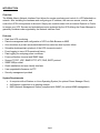
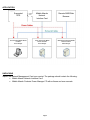
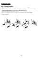
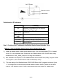
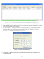
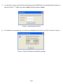
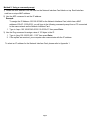
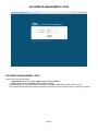
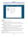
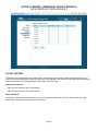
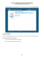
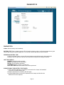
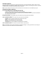
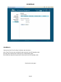
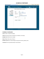
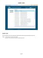
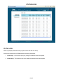
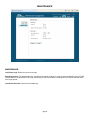
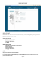
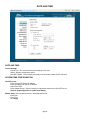
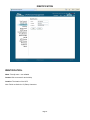
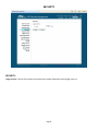
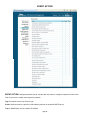
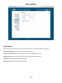
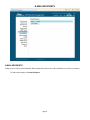
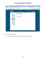
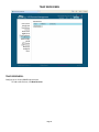
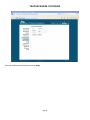
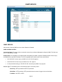
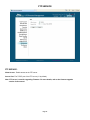
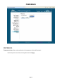
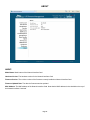
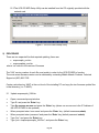
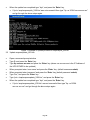
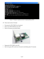
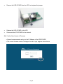
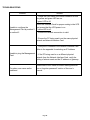
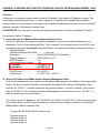
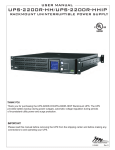
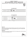
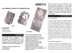
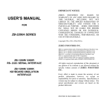
User’s Manual UPS SERIES Network Interface Card UPS-IPCARD I-00453 Rev B TABLE OF CONTENTS INTRODUCTION . . . . . . . . . . . . . . . . . . . . . . . . . . . . . . . . . . . . . . . . . . . . . . . . . . . . . . . . . . . . . 3 - 4 INSTALLATION GUIDE . . . . . . . . . . . . . . . . . . . . . . . . . . . . . . . . . . . . . . . . . . . . . . . . . . . . . . . 5 - 9 WEB INTERFACE (REMOTE MANAGEMENT) . . . . . . . . . . . . . . . . . . . . . . . . . . . . . . . . . . . .10 - 42 RESET TO DEFAULT SETTING/RECOVER FROM A FORGOTTEN PASSWORD . . . . . . . . . . . 43 FIRMWARE UPGRADE . . . . . . . . . . . . . . . . . . . . . . . . . . . . . . . . . . . . . . . . . . . . . . . . . . . . . . 43 - 47 TROUBLESHOOTING . . . . . . . . . . . . . . . . . . . . . . . . . . . . . . . . . . . . . . . . . . . . . . . . . . . . . . . . . . . 48 APPENDIX . . . . . . . . . . . . . . . . . . . . . . . . . . . . . . . . . . . . . . . . . . . . . . . . . . . . . . . . . . . . . . . . 49 - 50 Page 2 INTRODUCTION Overview The Middle Atlantic Network Interface Card allows for remote monitoring and control of a UPS attached to a network. After installing the hardware and configuring an IP address, the user can access, monitor, and control the UPS from anywhere in the world. Simply use a web browser such as Internet Explorer or Firefox to access your UPS. Servers and workstations can be protected by the UPS utilizing the Power Manager to gracefully shutdown when signaled by the Network Interface Card. Features z Real time UPS monitoring z Remote management and configuration of UPS via Web Browser or NMS z Auto-shutdown to protect servers/workstations from data lose due to power failure z Schedule shutdown/start-up/reboot of the UPS via remote control z Event logging to trace UPS operational history z Data logging for analyzing power conditions z Event notification via email and SNMP traps z Support TCP/IP, UDP, SNMP/HTTP, NTP, DNS, SMTP protocol z SNMP MIB provided z Quick installation and user friendly interface z User upgradeable firmware via FTP z Security management provided System Requirements • • • A computer with a Windows or Linux Operating System (for optional Power Manager Client) An Ethernet connection to an existing network NMS (Network Management Station) compliant with SNMP (for optional NMS management) Page 3 APPLICATION Supported UPS PC Protected by Middle Atlantic Products Power Manager CARD SLOT Middle Atlantic Network Interface Card Remote NMS/Web Browser Server Protected by Middle Atlantic Products Power Manager Workstation Protected by Middle Atlantic Products Power Manager UNPACKING Inspect the Network Management Card upon receipt. The package should contain the following: • • Middle Atlantic Network Interface Card. Middle Atlantic Products Power Manager CD with software and user manuals. Page 4 INSTALLATION GUIDE Step 1 - Hardware Installation 1) Turn off the UPS before removing the expansion port cover on the UPS. 2) Remove the two retaining screws from the expansion port cover and remove the cover. 3) Install the Middle Atlantic UPS-IPCARD into the expansion port. 4) Re-install and tighten the retaining screws. 5) Connect the Ethernet cable to the LAN port on the Middle Atlantic UPS-IPCARD. 6) Turn on the UPS. Page 5 Definitions for LED Indicators Link LED color Off On(Yellow) RX/TX LED color Off On(Green) Flashing RX/TX Indicator Ethernet connector LINK Indicator Condition The Network Management Card is not connected to the Network/or the Network Interface Card Power is off. The Network Interface Card is connected to the Network. The Network Interface Card power is off. The Network Interface Card power is on. - Receiving/transmitting data packet. - Reset finished. Step 2 - Configure the IP address for the Middle Atlantic Network Interface Card. Method 1: Using the Middle Atlantic Power Device Network Utility Tool 1) Install the Middle Atlantic Power Device Network Utility Tool from the included CD. It is located on the CD in the \software folder. Double click the “Middle Atlantic UPS-IPCARD Setup Utility” installation file, “MAP_SNMP_Setup.msi” to begin the installation. 2) After installation is complete, run the “Middle Atlantic UPS-IPCARD Setup Utility” program. Under “All Programs”, select “Middle Atlantic UPS-IPCARD Setup Utility.” 3) The main dialog of the “Middle Atlantic UPS-IPCARD Setup Utility” program is shown in Figure 1. The configuration tool will display all Middle Atlantic network cards of present on the same network. The "Refresh" button is used to search the entire local network for SNMP cards. Page 6 Figure 1. The main window of the “Middle Atlantic UPS-IPCARD Setup Utility” program. 4) Select the SNMP card you are setting up. Click on the Tools menu and select “Device Setup” or double click the SNMP card you want to configure. 5) You can modify the IP Address, Subnet Mask, and Gateway address for the Device MAC Address listed in the Device Network Settings window, as shown in Figure 2. The default IP Address is 192.168.20.177, the default Subnet Mask is 255.255.255.0. Figure 2 - The SNMP card-setting window 6) To modify the IP Address, Subnet Mask, or Gateway Address, enter the new addresses into the corresponding fields. Page 7 7) You will need to enter a User Name and Password for the SNMP card in the authentication window, as shown in Figure 3. *Default user name: admin; Default password: admin Figure 3 - Authentication window 8) If IP address is successfully set, you will see a message that the IP set up is OK, as shown in Figure 4. Figure 4 - Setup IP Address successfully message Page 8 Method 2: Using a command prompt 1) Obtain the MAC address from the label on the Network Interface Card labels on top. Each Interface card has a unique MAC address. 2) Use the ARP command to set the IP address. Example: To assign the IP Address 192.168.20.240 for the Network Interface Card, which has a MAC address of 00-0C-15-00-00-01 you will type in the following command prompt from a PC connected to the same network as the Network Interface Card. 1. Type in “arp-s 192.168.20.240 00-0C-15-00-00-01” then press Enter. 3) Use the Ping command to assign a size of 123 bytes to the IP. 1. Type in “ping 192.168.20.240 -1 123” then press Enter 2. If the replies are received, your computer can communicate with the IP address. To select an IP address for the Network Interface Card, please refer to Appendix 1. Page 9 UPS REMOTE MANAGEMENT LOGIN UPS REMOTE MANAGEMENT LOGIN: There are two user account types. - Administrator (default username: admin; default password: admin) - Viewer (default username: guest; default password: guest) The Administrator can access and control all functions, including enable/disable of the Viewer account. The Viewer’s access allows them read permissions for all functions but they cannot control or change any settings. Page 10 SUMMARY UPS SUMMARY: Current Condition: Displays the current operating condition of UPS UPS Status: Battery Capacity: Remaining battery capacity Load: Current load as a percentage of max. load Remaining Runtime: On battery run-time System Data: Name: UPS name (editable field) Location: UPS location (editable field) Contact: Primary contact (editable field) Uptime: Time since last power on Recent Device Events: Recently Occurring Events: The maximum number of events displayed is 5 (five) Page 11 STATUS STATUS: Input: Line Voltage: Current input voltage (utility power) Output: Voltage: Output voltage of the UPS Frequency: Output frequency Load: Load expressed as a percentage of maximum load Battery: Remaining Capacity: Remaining battery capacity Remaining Runtime: On battery run-time System: Temperature: Internal temperature of the UPS Page 12 INFORMATION INFORMATION: Model Name: The model name of the UPS Voltage Rating: The nominal operating voltage rating Operating Frequency: The frequency of the UPS input/output power Power Rating: The capacity of the UPS in Volt-Amperes (VA) Maximum Load: The capacity of the UPS in Watts Battery Voltage Rating: The DC voltage rating of the battery Firmware Version: The revision number of the UPS firmware Page 13 CONFIGURATION CONFIGURATION: Audible Alarm: Enable or disable audible alarms Page 14 CONTROL CONTROL: Reboot UPS: Turns the UPS off and back on Reboot Delay: How long the UPS waits before it turns off in response to a Reboot UPS Reboot Duration: Period of time between 'power off' and 'power on' following a Reboot command Standby Mode: Put UPS into standby mode Standby Delay: How long the UPS waits before it turns off in response to a Standby Mode Standby Delay: How long the UPS waits before it turns off in response to a Standby Mode Sleep Mode: Temporarily suspends UPS operation for a pre-defined period of time Sleep Mode Delay: How long the UPS waits before it turns off in response to Sleep Mode commands Sleep Duration: Period of time between entering and recovering from Sleep Mode command Notify Clients on Standby Mode: Alert Power Manager clients that UPS is entering Standby Mode Cancel: Cancels a pending action Click Next: The UPS will turn off in approximately 0 seconds. Once off, the UPS will restart after 10 seconds Page 15 OUTLET CONTROL (INDIVIDUAL OUTLET MODELS) (UPS-1000R-8-IP, UPS-2200R-8-IP) OUTLET CONTROL: The Outlet Control page displays the current state of, and provides on/off control for each individual outlet. Note: if a control PC has been assigned to a specific outlet within Power Manager, this outlet will be annotated with an asterisk (*). Select the outlet(s) to be controlled using the radio buttons and click Apply Outlet Control Options: On: Turns the selected outlet on immediately Off: Turns the selected outlet off immediately Edit Outlet Name: To change or update an outlet name simply click on the respective outlet name, enter the next text and click Apply. Outlet name is restricted to a maximum of 15 characters. Page 16 OUTLET CONTROL (BANK OUTLET MODELS) (UPS-1000R-IP, UPS-2200R-IP) OUTLET CONTROL: The Outlet Control page displays the current state of, and provides on/off control for the Non-Critical Outlet Bank. Non-Critical Outlet Bank Control Options: On: Turns non-critical outlet bank on immediately Off: Turns non-critical outlet bank off immediately Page 17 DIAGNOSTICS DIAGNOSTICS: Initiate: Start the battery test immediately BATTERY TEST: During a battery test the UPS will switch to battery mode to verify that the batteries are good. Use this test to perform a quick battery test. You can also view the date and time of the last test PERFORM A BATTERY TEST: 1. Click the “Initiate” button, and you will hear a beeping sound while the test is being performed 2. Battery Test will report the result after the latest test is completed and display as follows: LAST TEST RESULT: PASSED: The battery works normally. NONE: The battery has not been tested. FAILED: The UPS battery test failed. FORBIDDEN: Battery missing or internal error. LAST TEST DATE: Shows the date of the last test performed. SUGGESTIONS IF THE BATTERY TEST FAILED: 1. Clear “Remaining Runtime is Insufficient” event and/or the “Output is Overloaded” event and run another battery test. 2. Replace the batteries if the battery test fails again. 3. Contact Middle Atlantic Products for assistance if the battery test fails after the Batteries have been replaced. Page 18 RUNTIME CALIBRATION: The runtime calibration synchronizes the runtime estimate with the current load and battery capacity. When a runtime calibration initiates, the “Calibration is Initiated” event occurs. A runtime calibration will discharge the batteries completely. The batteries will be recharged automatically following a calibration Note: Frequent calibration will shorten the life of the batteries. We recommend one or two calibrations per year. PERFORM A RUNTIME CALIBRATION: ALL OUTLETS MUST BE ON TO PERFORM THIS FUNCTION 1. Click the “Start” button, this will initiate a runtime calibration 2. Click the “Cancel” button if you want to stop the runtime test before it is complete. The Runtime Calibration will display the results either after the calibration finishes or you cancel the calibration. The results will report as follows: ESTIMATED RUNTIME: The estimated runtime of the batteries under the present load conditions. LAST CALIBRATION RESULT: The result of the most resent runtime calibration. PASSED: Runtime calibration passed and the batteries are normal. NONE: A runtime calibration has not been performed. FAILED: The UPS failed during the runtime calibration. CANCELLED: The runtime calibration was stopped before completion. LAST CALIBRATION DATE: The date the last runtime calibration was performed. Note: The calibration process causes the batteries to completely discharge. If a utility power failure occurs during the calibration, the UPS will not support the connected equipment. Page 19 SCHEDULE SCHEDULE: Choose from One Time, Per Day, Per Week, and click Next>> [One Time]: The user may set a specific date and time for the UPS standby mode. [Per Day]: Set a specific time of the day for the UPS standby mode. [Per Week]: Set a specific day and time of the week for the UPS standby mode. - Continued on next page - Page 20 SCHEDULE CONTINUED SCHEDULE CONTINUED: Active: Enable or Disable this standby Outlet: Define which outlets to shutdown (not available on all models) Standby Time: Define when to standby Restore Time: Define when to Restore Shutdown Clients: Alert Power Manager Client(s) before entering standby mode Comment: Enter an optional description of this schedule Page 21 EVENT LOGS EVENT LOGS: Event logs display event history together with a date and time stamp, and a brief description of the event Notes: 1) Time stamp is in 24-hour clock format 2) Events to be recorded are listed under \system\event action Page 22 STATUS LOGS STATUS LOGS: Status logs display UPS status history together with a date and time stamp All items are the same as in UPS\status with the following exceptions: • Input min(V) - The minimum input (line) voltage recorded since the last snapshot • Input max(V) - The maximum input (line) voltage recorded since the last snapshot Page 23 MAINTENANCE MAINTENANCE: Clear Event Logs: Delete the current event logs Recording Interval: The data sample rate. A smaller time interval will allow for more frequent recordings but the UPS will maintain them for a shorter period. A longer interval will provide less frequent recordings, but the UPS will maintain them for a longer period. Clear Entire Records: Clears all current data logs Page 24 USER ACCOUNT USER ACCOUNT: Administrator: The administrator can access full functionality - includes enabling/disabling of the guest account Guest: The Guest has read only access Change admin account: Enter the current user name Enter the new password Confirm the new password Click Apply Change guest account: Select Allow Access to enable the guest account Enter the user name Enter the new password Confirm the new password Click Apply NOTES Only one user session at a time is permitted If you do not logout of the Remote Manager, the UPS-IPCARD will not allow a new session until the previous session times-out Page 25 DATE AND TIME DATE AND TIME: Current Settings: Date & Time - The current date and time settings of the card. Status - Displays configuration option Next NTP Update - The remaining time before next automatic update (if NTP selected) SYSTEM TIME CONFIGURATION: Use NTP Server: Enter Primary NTP Server IP address Enter secondary NTP Server IP address Select Time Zone Enter Update Interval - Set the frequency to update the date and time from NTP server. (Choose Update Right Now to update immediately) Manual Setup: Enter the date and time in the designated format Enter Date Enter Time Click Apply Page 26 IDENTIFICATION IDENTIFICATION: Name: Friendly name - user editable Contact: Who to contact for service/help Location: The location of the UPS Note: Fields are limited to 15 (fifteen) characters Page 27 SECURITY SECURITY: Login Session: Timeout The period (in minutes) that the system waits before auto-logging users out Page 28 EVENT ACTION EVENT ACTION: Displays all possible events, and provides the means to configure responses to each event. Click on the event to modify each respective response. Log: Records the event in the "Event Logs" E-mail: Sends an email to a specific e-mail address (requires an accessible SMTP server) Trap: A SNMP trap is sent to a specific IP address Page 29 SMTP SERVER SMTP SERVER: After configuring the SMTP server, the UPS can send an email to users when a specific event occurs. Server's IP/Host Name: The IP or host name of the SMTP server Sender's E-mail Address: 'From' field as shown in the e-mail message sent to user Authentication: Select this option if the SMTP server requires authentication check Username: Username used for SMTP authentication Password: Password used for SMTP authentication Page 30 E-MAIL RECIPIENTS E-MAIL RECIPIENTS: Configure up to 5 (five) e-mail recipients. Each recipient will receive an e-mail notification on an 'Event' occurrence. To add a new recipient, click New Recipient. Page 31 E-MAIL RECIPIENTS CONTINUED Enter the email address and click Apply To modify or delete an existing recipient, click the e-mail address of that recipient. Page 32 TRAP RECEIVERS TRAP RECEIVERS: Configure up to 10 (ten) SNMP trap receivers. To add a new receiver, click New Receiver Page 33 TRAP RECEIVERS CONTINUED Enter the IP Address and Community and click Apply Page 34 TRAP RECEIVERS CONTINUED - To modify or delete an existing receiver, click the IP Address of that receiver. Note: When Middle Atlantic Power Manage connects to a UPS, the IP address of the host machine will be added to the list of trap receivers automatically. Page 35 CLIENT STANDBY CLIENT STANDBY: Clients Standby Delay: The longest standby delay time required for connected Power Manager client(s) Force Negotiation: Select to re-negotiate the standby delay with Power Manager clients. The Client's standby delay reverts to the default setting of 2 (two) minutes, but allows a negotiation time of up to 10 minutes. Page 36 TCP/IP TCP/IP: Current Configuration: Displays the current TCP/IP settings: IP address, subnet mask, gateway, primary DNS server DHCP Enable: Select this option and click Apply to enable DHCP • DHCP Enabled - Choose this option to get IP the address, subnet mask, and gateway. • Obtain DNS Address from DHCP - Select the option to get the DNS by DHCP if DHCP is enabled. Manual Configuration: To disable DHCP, enter the TCP/IP settings manually and click Apply. Page 37 HTTP SERVICE HTTP SERVICE: Allow Port: The TCP/IP port of the Hypertext Transfer Protocol (HTTP) (80 is the default) Page 38 SNMP SERVICE SNMP SERVICE: Allow Access: Sets the SNMP service to either Enabled or Disabled SNMP ACCESS CONTROL Community Name: The name used to access this community by a Network Management System (NMS). The field must be 1 to 15 characters in length. IP/Host Name: The IP address or IP address mask accessible by the NMS. A specific IP address allows access only by the NMS with the specified IP address. The 255 is regarded as the mask and the rules are as follows: • 192.168.20.255: Access only by an NMS on the 192.168.20 segment • 192.255.255.255: Access only by an NMS on the 192. segment • 0.0.0.0 (the default setting) or 255.255.255.255: Access by any NMS on any segment Access Type: The allowable action for the NMS through the community and IP Read Only - GETs permitted but SETs not permitted Write/Read - GETs permitted, SETs permitted unless someone is logged in the web interface Forbidden - No GETs or SETs Page 39 FTP SERVICE FTP SERVICE: Allow Access: Enable access to the FTP server Access Port: The TCP/IP port of the FTP server (21 by default) Note: FTP server is used for upgrading Firmware. For more details, refer to the firmware upgrade section of this manual. Page 40 PREFERENCE PREFERENCE: Temperature Scale: Selects the preferred unit of temperature (Celsius/Fahrenheit) - Select the preferred unit from the dropdown and click Apply Page 41 ABOUT ABOUT: Model Name: Model name of the Network Interface Card Hardware Version: The hardware version for the Network Interface Card Firmware Version: The revision number of the firmware currently installed on Network Interface Card Firmware Updated Date: The date the firmware was last updated MAC Address: The MAC address of the Network Interface Card. Note that the MAC address is also detailed on the top of the Network Interface Card itself Page 42 Reset to Default Setting/Recover from a Forgotten Password To reset the Middle Atlantic Network Interface Card to its default setting (including WEB login user name and password), use the following steps. RESET 1) 2) 3) 4) 5) 6) 7) 8) 9) Remove the two retaining screws on the card without turning off the UPS. Remove the card from the expansion port. Remove the jumper on the Reset pins as illustrated.(The jumper is still necessary after reset , please do not lose or dispose of it) Re-install the card into the expansion port. Wait until the Green LED (RX/TX) is flashing (the frequency of the ON/OFF flashing is one second). Remove the card from the expansion port. Re-install the jumper on the reset pins. Re-install the card into the expansion port. Re-install and tighten the retaining screws. Firmware Upgrade 1) INITIAL SETUP 1.1 Ensure that the UPS-IPCARD to be upgraded is correctly installed in the UPS, and that the UPS is powered on. 1.2 Connect the UPS-IPCARD to the network and use “UPS-IPCARD Setup Utility” to locate and identify the card to be upgraded. See figure 1 below: 1.2.1 Please note that the UPS-IPCARD Setup Utility will identify all UPS-IPCARDs that are on the same subnet. Please take care to ensure that you have identified the correct card before proceeding. 1.2.2 Please note that if the computer and the UPS-IPCARD to be upgraded are not on the same subnet, the default gateway must be configured to correctly route between the two subnets . Page 43 1.2.3 The UPS-IPCARD Setup Utility can be installed from the CD originally provided with the network card. Figure 1: UPS-IPCARD Setup Utility 2) PROCEDURE There are two separate files that required updating; these are: • mapsnmpfw_xxx.bin • mapsnmpdata_xxx.bin where ‘xxx’ refers to the version of firmware The ‘XXX’ version number of each file must match in order for the UPS-IPCARD to function. The most recent firmware version can be obtained by contacting Middle Atlantic Products Technical Support at (800) 266-7225 Create a sub-directory ‘MAP’ at the root level of the installing PC and copy the two firmware update files to that directory (i.e. C:\MAP\). 2.1 Update mapsnmpfw_XXX.bin • • • Open a command prompt window Type C: and press the ‘Enter’ key. Type ftp xxx.xxx.xxx.xxx and press the ‘Enter’ key (where xxx.xxx.xxx.xxx is the IP Address of the UPS-IPCARD to be updated) • • • • When prompted enter ’user name’ and press the ‘Enter’ key (default username;admin) When prompted enter ‘password’ and press the ‘Enter’ key (default password: admin) Type “bin”, and press the ‘Enter’ key. Type “put c:\map\mapsnmpfw_XXX.bin”, and press the ‘Enter’ key Page 44 • When the update has completed type “bye”, and press the ‘Enter’ key • If ’put c:\map\mapsnmpfw_XXX.bin’ was not successful then type ”ftp –w:16384 xxx.xxx.xxx.xxx” and go through the above steps again. Figure 1: Example of update process for mapsnmpfw_xxx.bin 2.2 Update mapsnmpdata_XXX.bin • • • Open a command prompt window Type C: and press the ‘Enter’ key. Type ftp xxx.xxx.xxx.xxx and press the ‘Enter’ key (where xxx.xxx.xxx.xxx is the IP Address of the UPS-IPCARD to be updated) • • • • • When prompted enter ’user name’ and press the ‘Enter’ key (default username:admin) When prompted enter ‘password’ and press the ‘Enter’ key (default password: admin) Type “bin”, and press the ‘Enter’ key. Type “put c:\map\mapsnmpdata_XXX.bin”, and press the ‘Enter’ key When the update has completed type “bye”, and press the ‘Enter’ key • If ’put c:\map\mapsnmpdata_XXX.bin’ was not successful then type ”ftp –w:16384 xxx.xxx.xxx.xxx” and go through the above steps again. Page 45 Figure 2: Example of update process for mapsnmpdata_xxx.bin 2.3 Clear current version of firmware • • • Disconnect the UPS-IPCARD from the network. Remove the UPS-IPCARD from the UPS. Remove the jumper (as indicated below). • • Replace the UPS-IPCARD in the UPS. Wait for the green LED on the front of the card to start blinking (about 10 seconds). Page 46 • Remove the UPS-IPCARD from the UPS, and replace the jumper. • • Replace the UPS-IPCARD in the UPS. Reconnect the UPS-IPCARD to the network. 2.4 Confirm New Version of Firmware Open a browser session and go to the IP Address of the UPS-IPCARD The current firmware version is displayed on the ‘Login’ page as shown below Page 47 TROUBLESHOOTING Problem Solution 1. Check the LED status, the normal condition is both the yellow and green LED are on. If green LED is off: Check the Interface Card for proper seating in the UPS Unable to configure the and ensure that the UPS power is on. Management Card by method 1 If yellow LED is off: or method 2 1. Ensure the network connection is valid 2. Ensure the PC being used is on the same physical network as Network Interface Card. 1. Verify the IP Address of the Network Interface Card. Refer to the appendix for selecting an IP Address Unable to ping the Management 2. If the PC being used is on a different physical Card network from the Network Interface Card, verify the setting of subnet mask and the IP address of gateway. Forgotten user name and/or password Please refer to the “Reset to Default Setting/Recover from a forgotten password” section of the user’s manual. Page 48 APPENDIX: IP ADDRESS SETTINGS FOR THE MIDDLE ATLANTIC NETWORK MANAGEMENT CARD Overview All devices on a computer network need to have an IP address. Each device’s IP address is unique. The same address cannot be used twice. In order to assign an IP address to the Middle Atlantic Network Interface Card, you must determine the range of the available IP addresses, and then choose an unused IP address to assign to the Network Interface Card. PLEASE NOTE: You may need to contact your network administrator to obtain an available IP address. Procedures to find an IP address: 1) Locate the subnet of Middle Atlantic Network Interface Card. One way to determine the range of possible IP addresses is to view the network configuration on a workstation. Click on [Start] and select [Run]. Type “command” into the open box and click [OK]. At the command prompt type “ipconfig/all” and press [Enter]. The computer will display network information: Ethernet adapter Connection-specific DNS Suffix…………: xxxx.com Description…………………..…: D-Link DE220 ISA PnP LAN adapter Physical Address…………..….: 00-80-C8-DA-7A-C0 DHCP Enabled……………......: Yes Auto configuration Enabled …..: Yes IP Address……………..……..: 192.168.20.102 Subnet Mask…………...……..: 255.255.255.0 Default Gateway……..…….....: 192.168.20.1 DHCP Server………………….: 192.168.20.1 DNS Servers………………..…: 211.20.71.202; 168.95.1.1 2) Select an IP Address for Middle Atlantic Network Management Card Verify the IP Addresses for the computer and the Network Management Card belong to the same subnet. Refer to the above network information, the possible IP Address for the Network Management Card could be 192.168.20.* (* hereafter represents any number between 1 and 255). Similarly, if the Subnet Mask is 255.255.0.0, the IP Address for Network Management Card could be set up as 192.168.*.* to reach the same subnet as the computer. If you wish to set the IP Address to 192.168.20.240, type “Ping 192.168.20.240” in the command prompt. If the request times out (See Figure) the address is most likely not used and available for use with the Middle Atlantic Network Interface Card Pinging 192.168.20.240 with 32 bytes of data: Request timed out. Request timed out. Request timed out. Request timed out. Page 49 FIGURE AND PROMPT Any other response indicates the IP Address selected is not available (See Figure). Select another IP Address and repeat “ping” command until an available address is found. Pinging 192.168.20.240 with 32 bytes of data: Reply from 192.168.20.240: bytes=32 time<10ms TTL=64 Reply from 192.168.20.240: bytes=32 time<10ms TTL=64 Reply from 192.168.20.240: bytes=32 time<10ms TTL=64 Reply from 192.168.20.240: bytes=32 time<10ms TTL=64 FIGURE AND PROMPT Page 50