1
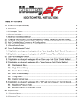
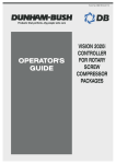
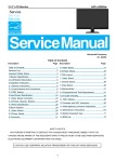
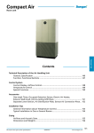
Form No: MM0214A / MM0215A
®
Products That Perform . . .By People Who Care
Water- Cooled
Single Package
Air-Conditioner
with Scoll Compressors
R22 / R407C
50 / 60 Hz
WCPS-B Series
TABLE OF CONTENTS
MANUAL INDEX
PAGE
1.0 INTRODUCTION................................................................................................................................................................... 3
2.0 GENERAL INFORMATION
2.1
SAMPLE NOMENCLATURE ................................................................................................................................................. 4
2.2
2.3
2.4
RECEIVING, INSPECTION AND PACKAGING........................................................................................................................ 4
RIGGING AND UNCRATING................................................................................................................................................. 5
LIMITATIONS...................................................................................................................................................................... 5
3.0 INSTALLATION
3.1
FOUNDATION ..................................................................................................................................................................... 6
( i.) Provide A Separate Floating Plinth.................................................................................................................................. 6
( ii.) Place The Unit On A Minimum 2½” Thick Cork Sheet ........................................................................................................ 7
( iii.) Support The Complete Unit On Spring Isolators. Request Factory To Provide
Correct Spring Isolators And Mounting Brackets At Base Units............................................................................................ 7
3.2
LOCATIONS ....................................................................................................................................................................... 7
3.3
CLEARANCE...................................................................................................................................................................... 7
Figure 3.3A: For Units With Single Side Return Air, WCPS 68B To 570B ...................................................................................... 8
Figure 3.3B: For Units With Single Side Return Air, WCPS 640B To 1520B ................................................................................... 9
3.4
UNPACKING AND UNCRATING.......................................................................................................................................... 10
3.5
BLOWER SECTION ........................................................................................................................................................... 10
3.5.1 Discharge Pattern .................................................................................................................................................... 10
3.5.2 Duct Connections .................................................................................................................................................... 10
Figure 3.5.1: Blower Discharge Pattern .......................................................................................................................... 11
Figure 3.5.2: Suggested Method For Connecting Supply Duct To Twin Blower Unit .............................................................. 12
3.6
EVAPORATOR SECTION ................................................................................................................................................... 12
Figure 3.6: Condensate Drain Trap ....................................................................................................................................... 12
3.7
CONDENSER SECTION ..................................................................................................................................................... 13
3.8
COOLING TOWER ............................................................................................................................................................ 13
Figure 3.8A: Cooling Tower Water Piping Schematic ............................................................................................................... 14
Figure 3.8B: Unit Control On Water Flow ............................................................................................................................... 14
Figure 3.8C: Alternate Unit Control On Water Flow .................................................................................................................. 14
4.0 OPERATION
4.1
4.2
4.3
SYSTEMS CAPACITY........................................................................................................................................................ 15
SYSTEM WATER FLOW .................................................................................................................................................... 15
TEMPERATURE CONTROL ................................................................................................................................................ 15
4.4
4.5
TEMPERATURE SETTING ................................................................................................................................................. 16
PHASE ROTATION ............................................................................................................................................................ 16
4.6
4.7
4.8
CYCLE LIMIT RATE........................................................................................................................................................... 16
HOT GAS BYPASS............................................................................................................................................................ 16
REFRIGERANT CIRCUIT AND COMPONENTS ..................................................................................................................... 17
Figure 4.8: Typical Refrigerant Piping And Components ........................................................................................................... 17
4.9
TYPICAL OPERATING SEQUENCE FLOW CHART............................................................................................................... 18
4.10 START UP CHECKLIST ..................................................................................................................................................... 19
4.11 TYPICAL WIRING SCHEMATIC WITHOUT STARTER ........................................................................................................... 20
4.12 TYPICAL WIRING SCHEMATIC WITH DOL .......................................................................................................................... 20
4.13 TYPICAL WIRING SCHEMATIC WITH AUTOTRANS ............................................................................................................. 21
5.0 MAINTENANCE
5.1
GENERAL ........................................................................................................................................................................ 22
5.2
SCHEDULE OF INSPECTION AND MAINTENANCE.............................................................................................................. 22
5.2.1 Monthly Inspection And Maintenance ........................................................................................................................ 22
5.2.2 Three Monthly Inspection And Maintenance ............................................................................................................... 22
5.2.3 Annual Inspection And Maintenance.......................................................................................................................... 22
5.3
CONDENSER MAINTENANCE............................................................................................................................................ 23
5.3.1 General .................................................................................................................................................................... 23
5.3.2 Condenser Cleaning................................................................................................................................................. 23
5.3.3 Tube Replacement.................................................................................................................................................... 24
5.4
5.5
WATER TREATMENT ........................................................................................................................................................ 24
TIGHTENING OF BEARING SET SCREW ............................................................................................................................ 24
5.6
5.7
PULLEY ALIGNMENT........................................................................................................................................................ 25
BELT TENSION INSPECTION GUIDE.................................................................................................................................. 25
5.8
5.9
TROUBLE-SHOOTING CHART ........................................................................................................................................... 27
SAMPLE LOG SHEET ........................................................................................................................................................ 30
1.0 INTRODUCTION
This equipment is factory manufactured and tested water-cooled package for the
purpose of air-conditioning. It consists mainly of a direct expansion evaporator
coil(s) with thermal expansion valve, scroll compressor(s) and water-cooled
cleanable shell and tube condenser(s). Factory standard units also incorporate
important safety and operating controls which includes manual reset high and
low pressure switch, compressor motor protectors, sight glass and liquid line
filter drier for each compressor.
The water-cooled air-conditioner package consists of multiple compressors
(Except WCPS / 6WCPS 68B~190B) each with its own independent refrigerant
circuit, which guarantee standby partial capacity in case of failure of any one
compressor. It is equipped with cleanable shell and tubes condenser(s) which
enable economical and easier cleaning of condenser inner water tubes by brushes
instead of by chemical cleaning for co-axial tubes-in-tube condenser. The shell
and tubes condenser also has a lower waterside pressure drop compared with coaxial tubes-in-tube condenser. Further more, any punctured inner tubes of the
shell and tubes condenser can be replaced instead of scrapping the whole
condenser in the case of the co-axial tubes-in-tube condenser.
Every Dunham-Bush water-cooled single package air-conditioner has been
carefully and intelligently designed, manufactured and tested. It is also subject to
stringent quality control and accurately tested as a final verification of reliability.
If it is correctly installed, operated and maintained, it will provide many years of
satisfactory and efficient performance.
These instructions are general in nature and are for
standard units only. Non-standard units may vary in some
respects from these instructions to suit particular
applications.
2.0 GENERAL INFORMATION
2.1 SAMPLE NOMENCLATURE
6 WCP S 640 B Q P
Blank - 50Hz
6
- 60Hz
Blank - R22
P
- R407c
Water Cooled Packaged
Blank - Standard
Q
- Special
Generation
S - Scroll Compressor
R - Reciprocating
Compressor
Model Code
2.2 RECEIVING, INSPECTION AND PACKAGING
As soon as the unit is received, it should be inspected for any damage during transit. Make a
separate written request if there is any damage on the carrier's delivery order.
Also the unit should be inspected for any missing or short-shipped components Standard items
and accessories that came with the unit are:
1.) Compressor(s) complete with rubber mounting grommet.
2.) Shell and tubes condenser(s).
3.) Evaporator complete with thermal expansion valve(s).
4.) Manual reset high and low pressure switch for each compressor.
5.) Sight glass and liquid line filter drier for each compressor.
6.) Blowers and relevant supports ( motor mounting plate, bearings and shaft ).
7.) Flexible canvas connections for blower outlets.
Other optional accessories includes:
1.) Thermostat.
2.0 GENERAL INFORMATION
2.) Supply air plenum.
3.) Return air grille and integral filter frame.
4.) Hot water heating coils or electric reheaters.
5.) Compressor time delay relay.
6.) Factory wired starter board.
7.) Hot gas by pass, oil separator and suction accumulator.
8.) Copper, hydrophilic fins or tinned coated copper fins.
9.) Pressure gauges.
10.) Suction stop valve(s), discharge stop valve(s) and liquid stop valve(s).
11.) External spring vibration isolators for blower fan and drive assembly.
2.3 RIGGING AND UNCRATING
Each unit has been tested, inspected and properly packed or crated prior to delivery. It is very
important that precaution is taken in handling the units by the installers, movers and riggers.
Lift with slings under the units with a forklift. When lifting with slings, use spreader bars
across the top of the unit to prevent any damage to the frame and panels. Rigging should be
done in a manner to avoid any severe strain or stress on the unit which will scratch the paint
work, damage the panels and framework. Avoid possible surface damage by not removing the
packaging material until the unit is at or near the final location and soon to be installed. Check
the weight of the unit before rigging. Try to place the rigging cable such that the weight is
evenly distributed.
2.4 LIMITATIONS
1.) Avoid excessive condenser water flow rate, low water temperature and low return air
temperature, which may cause low discharge refrigerant pressure, liquid slug back to
compressor and condensate to freeze up the surface of the evaporator coil.
2.) An excessively low gpm with high water temperature may cause compressor shut down on
high-pressure trip.
3.) Avoid too high air face velocity on evaporator coil. Too high air face velocity will create
noise and cause moisture carry over. Maximum face velocity is 600 fpm.
4.) Standard units are not meant for outdoor installation, unless weatherproofing is specified to
factory.
5.) Unit must be operated on the correct electrical supply as specified on unit nameplate.
Voltage limitation for compressor(s) and fan motor must be observed.
3.0 INSTALLATION
3.1 FOUNDATION
The unit shall be placed on a flat, level, solid foundation ( plinth ) or floor capable of
supporting the weight of the unit. No special foundation or vibration isolator is generally
required as the vibration transmitted from the units casing will not adversely effect the
surrounding.
In extreme cases when it is necessary to completely isolate any vibration from the airconditioner or when any vibration from the air-conditioner can adversely affect any other
nearby equipment, it is recommended that either one of the following methods be followed:
i.)
Provide a separate floating plinth
WCPS-B
FLOATING
PLINTH
MIN 8"
CONCRETE
PLINTH
FLOOR
ii.)
Place the unit on a minimum 2½" thick cork sheet.
WCPS-B
CORK
SHEET
FLOOR
3.0 INSTALLATION
iii.) Support the complete unit on spring isolators. Request factory to provide
correct spring isolators and mounting brackets at base units.
WCPS-B
FACTORY PROVIDED
MOUNTING BRACKETS
2" DEFLECTION
SPRING
ISOLATORS
NON-SKID
NEOPRENE PAD
6-1/2"
1"
FLOOR
3.2 LOCATIONS
The recommended location for the units to facilitate operation and reduce cost is to locate it:
1.) Near power supply source
2.) Near drain source
3.) Near water source
The standard units are not weatherised for outdoor installation. For installation demanding
extreme quiet operation, locate WCPS-B air-conditioner outside conditioned space with both
supply and return air ducts connected to unit or provide sound attenuators on both supply and
return side.
3.3 CLEARANCE (See Figures 3.3A & 3.3B)
Clearance must be provided for:
1.) Supply and return air ductwork ( If there are ).
2.) Condenser water piping.
3.) Electrical power and control wiring.
4.) Trapped condensate drain connection.
5.) Maintenance and service access to compressors, fan motor and drive, control panel,
condensers, filter drier, sight glass and expansion valves.
6.) Return air ( for free air return ).
3.0 INSTALLATION
FIGURE 3.3A: FOR UNITS WITH SINGLE SIDE RETURN AIR, WCPS 68B TO 570B
Side
Recommended
Minimum
Clearance
Remark
1.) Return air, front
48"
For proper air intake to the condenser coil.
2.) Rear (Vertical discharge)
48
For access to compressors, controls, filter drier, sight
glass, fan motor and drive assembly. Unless otherwise
specified, compressors and controls are fitted for access
from rear sides of units.
3.) Top
a.) Vertical discharge
Please refer
table for proper
duct connection.
2"
For proper duct connection to avoid high discharge air
turbulence which can create excessive noise or
drumming at discharge duct.
For removal of top panels, if necessary.
4.) Side with piping connection
(unless otherwise specified,
condenser inlet and outlet
connections and condensate
connection are located on right
side of unit).
36"
For proper piping connection and access to valve
fittings, strainer, thermometer, pressure gauges, flow
switch etc. which may be fitted to the condenser inlet
and outlet pipings. Also for access to fan motor and
drive, if located on this side.
5.) Side opposite
connection
60"
For brush cleaning of inner water tubes of shell and
tubes condenser(s). Brush cleaning of inner water tubes
can be accomplished by removing the end water boxes
(opposite piping connection) of each condenser. Also for
access to fan motor and drive if located on this side.
-
Allow enough clearance to trap the emergency drain
line.
b.) Rear discharge
6.) Bottom
of
piping
3.0 INSTALLATION
FIGURE 3.3B: FOR UNITS WITH SINGLE SIDE RETURN AIR, WCPS 640B TO
1520B
Side
Recommended
Minimum
Clearance
Remark
1.) Return air, front
48"
For proper air intake to the condenser coil.
2.) Rear
(Vertical discharge)
48"
For access to compressors, controls, filter drier, sight glass,
fan motor and drive assembly.
Please refer table
for proper duct
connection.
For proper duct connection to avoid high discharge air
turbulence which can create excessive noise or drumming at
discharge duct.
3.) Top
a.) Vertical discharge
b.) Rear discharge
2”
For removal of the panels, if necessary.
4.) Side with piping
connection
36"
For proper piping connection and access to valve fittings,
strainer, thermometer, pressure gauges, flow switch etc.
which may be fitted to the condenser inlet and outlet
pipings. Also for access to fan motor and drive if located on
this side.
5.) Side opposite of piping
connection
60
For brush cleaning of inner water tubes of shell and tubes
condenser(s). Brush cleaning of inner water tubes can be
accomplished by removing the end water boxes (opposite
piping connection) of each condenser. Also for access to fan
motor and drive if located on this side.
6.) Bottom
-
Allow enough clearance to trap the emergency drain line.
3.0 INSTALLATION
3.4
UNPACKING AND UNCRATING
Unless specified, the units are generally not wooden crated. Only light packaging with wooden
skid and wrapped around shrink-fit polystyrene sheet for waterproofing are provided. Care
should be taken in handling, moving or rigging the units to avoid damaged to the panels, paint
work and framework. All units or sections should be moved or trucked to their final location in
the vertical position. Under no circumstances should they be "walked" on the corners of the
units or crates.
1.) Remove shipping carton or crate.
2.) Remove skid from under the units
3.) Remove the rear access panel of the condensing section for access to the electrical box and
the compressor(s).
3.5
BLOWER SECTION
3.5.1 Discharge Pattern
Four blower discharge patterns are generally available for all models ( i.e. Patterns 1 to
4 as shown in Figure 3.5.1 ).
It is important to study the site layout and select the type of blower discharge pattern
to suit the ductwork direction which will minimize noise and vibration. The selected
blower discharge pattern should be specified in the purchase order ( or order form ) to
the factory. Avoid field conversion of blower discharge pattern! If field conversion of
the blower discharge pattern is required, contact factory or nearest Dunham-Bush
representative, and the field conversion should only be carried out under the
supervision of a factory authorized personnel.
3.5.2 Duct Connections
All ducts should be made in accordance with all local and/ or national codes and with
goods duct installation practices. Try to minimize unnecessary static losses by having
many bends.
Suspended ductwork with flexible hangers should not be fastened directly to the unit.
A length of straight duct shall be installed as per Figure 3.5.2. This is to ensure
uniform flow of discharge air. If an elbow need to be installed, then it shall be 1.5 of
equivalent duct diameter. Z(Equivalent duct Ø= (4ab/π)0.5 ).
Please refer to AMCA standard for proper ducting installation/ guidelines.
3.0 INSTALLATION
FIGURE 3.5.1: BLOWER DISCHARGE PATTERN
1. WCPS 68B to 570B
PATTERN NO: 1
PATTERN
NO: 2
PATTERN
NO: 3
2. WCPS 640B to 1520B
PATTERN NO: 1
PATTERN NO: 2
PATTERN NO: 3
PATTERN NO: 4
PATTERN
NO: 4
3.0 INSTALLATION
FIGURE 3.5.2 SUGGESTED METHOD FOR CONNECTING SUPPLY DUCT
Model
A
B
68-160
40
25
190-510
60
35
570-1520
80
50
3.6 EVAPORATOR SECTION
1.) For all models, return air is through front of the unit.
2.) The standard unit has three or four row deep coils.
3.) The thermal expansion valve(s) and distributor(s) are at the left end of the units viewing
from the return airside (same as condenser and drain piping connections).
4.) Filters are located at the return airside (refer to table for quantities and sizes). It can be
taken out for servicing by removing one side of the filter holding frame.
5.) Fans rpm shall be selected within the range of the Blower Performance Table. For
operation outside the Blower Performance Table, consult factory or nearest Dunham-Bush
representative.
6.) Maximum motor hp size for each model shall be observed. If larger than standard motor
size is required, consult factory or nearest Dunham-Bush representative.
7.) Condensate drain should be trapped as shown in Figure 3.6.
FIGURE 3.6: CONDENSATE DRAIN TRAP
3.0 INSTALLATION
3.7 CONDENSER SECTION
1.) All internal condenser water piping is completely factory assembled and pressure tested at
300 psig for leakage. The condenser is designed to withstand a working pressure of 175
psig on the waterside.
2.) The standard units condenser and drain connections are on the right hand side viewing
from the front side (i.e. The return air side).
3.) Water piping should include stop (isolation) valves so that any unit can be serviced without
shutting down and draining the entire system.
4.) Flexible joints shall be fitted when connections are made with the unit condenser water
inlet and outlet connections.
5.) Install a strainer in the line to the condenser especially when water supply is contaminated.
6.) To install water pressure gauges, thermometer wells complete with thermometer on both
inlet and outlet condenser water pipings. The readings are useful for trouble-shooting and
analysis of system performance.
7.) A water regulating valve controlling the flow of the condenser water to each condenser
shall be installed whenever condenser inlet water temperature may fall below 60°F. A
water pressure reducing valve must also be installed in the condenser water inlet line, if
pressure can exceed 175 psig.
3.8
COOLING TOWER
Where water costs are high or water is not plentiful, an outdoor or indoor forced or induced
draft-cooling tower is recommended for condenser water.
Cooling towers must be selected for the specific conditions of each application. Local
representatives of cooling tower manufacturers will assist in selecting the proper size tower for
each installation.
When installing a cooling tower system,
1.) Avoid using long run of pipe exposed to the sun.
2.) If freezing is a problem, provisions for draining system or cycling off the fans should be
incorporated. Try to run as much piping indoors as possible.
3.) In case of frequent interruption of city water supply, a water storage tank with automatic
control valve is required to ensure continuous make-up water to the cooling tower.
Refer to condenser water-cooling tower piping schematic in Figure 3.8A.
Figure 3.8A illustrates the piping including a bleed-off valve and strainer in the suction line to
the pump. The bleed-off is needed to keep the concentration of salts down, especially in areas
having hard water.
The bypass is used to permit circulation of a larger quantity of water over the tower than
through the condenser. This allows the tower to operate at greater efficiency without suffering
the pressure drop though the condenser.
It is recommended that the cooling tower/ pump operation be controlled with the units(s).
Methods of control are shown in Figures. 3.8B and 3.8C.
3.0 INSTALLATION
FIGURE 3.8A:
COOLING TOWER WATER PIPING SCHEMATIC
Figure 3.8B shows the suggested wiring arrangement necessary to interconnect the unit, pump
and tower fan motor. The entire system starts and stops automatically.
Figure 3.8C shows an alternate wiring arrangement. Each unit is individually controlled by its
room thermostat. The unit control circuit is energized by the pump motor starter. Starting the
pump motor also starts the tower fan.
After the pump is started manually, it will continue to operate until the stop button is pushed.
This arrangement is suggested where there will be a long run of condenser water piping that
might be heated excessively during the off periods with automatic operation.
In each case, the wiring is such that there is water circulation through the condenser when units
are running.
FIGURE 3.8B: UNIT CONTROL
WATER FLOW
* 220VA available per unit for cooling tower pumps and fans
ON
FIGURE 3.8C: ALTERNATE UNIT
CONTROL ON WATER
FLOW
* 220VA available per unit for cooling tower pumps and fans
4.0 OPERATION
4.1 SYSTEM CAPACITY
An accurate load calculation is essential because selection of units is based on the required
total and sensible load at the specified conditions (i.e. Water temperature off condenser,
DB/WB F air on evaporator coil). Undersizing the unit might cause premature failure (Due to
overloading of compressor) and the room design condition will not be attained. Excessively
oversizing the unit will waste in terms of first and operating cost.
For a single compressor unit, capacity unloading is by on/off operation of the compressor in
response to a single stage thermostat.
For multiple compressors units, capacity control is by staging of multiple compressors
operation in response to a multi-stage thermostat (Maximum 4 steps unloading).
Supply air volume through the evaporator must be selected within the airflow limits for proper
operation. Too low air volume can cause the low pressure cut-out to trip at 35 psig, cause
freeze-up of evaporator coil, liquid slugging into compressor and thus causing damage to the
compressor.
In general, saturated suction pressure should not be below 58 psig (Equivalent to 32°F
saturated suction temperature). Operating the unit with excessively high airflow can create
noise and vibration, and cause moisture carry over. (Low-pressure trip may also indicate
system refrigerant leakage and lack of refrigerant charge). Consult factory if the selected unit
has to operate outside the airflow limitation.
4.2 SYSTEM WATER FLOW
One or more pumps must be selected to meet the required water flow rate and pressure loss in
the condenser water circuit. Low-pressure drop indicates insufficient water flow rate while too
high-pressure drop indicates the opposite. The condenser is designed for a fouling factor of
0.001. Excessive fouling and scaling in the condenser circuit can cause the system to operate
on high head pressure thus loss of cooling capacity, high power consumption and eventually
high pressure cutout. Too high water flow rate, on the other hand will cause excessive erosion
on the condenser inner water tubes.
4.3 TEMPERATURE CONTROL
Temperature control is via thermostat which should,
1.) be located about 5 ft. above the floor.
2.) be exposed to normal room air circulation.
3.) not be mounted on outside wall.
4.) not be exposed to radiant effects.
5.) be enclosed in protective cage and locked when exposed to tempering or damage.
4.0 OPERATION
4.4 TEMPERATURE SETTING
Normally the temperature setting for,
a.) Cooling is 75-80°F
b.) Heating is 70°F ( If heating coil is available ).
4.5 PHASE ROTATION
If during initial start up the compressor does not build up pressure, noise is abnormally load
and power consumption is minimal, then there is a possibility that the unit is operating in
reverse rotation. Shut down the power connection and connect wire to the proper terminals.
4.6 CYCLE LIMIT RATE
Each compressors must not be cycle on-off for more than 12 times per hour. The higher
number of starts per hour will reduce the life of the compressor. Thus, it is suggested that anti
short cycle timer is provided in the system.
4.7 HOT GAS BYPASS
The purpose of the hot gas by pass is to create artificial load in the system by means of
injecting hot gas into the inlet of the distributor. This would prevent the suction pressure from
falling below the desired settings and thus causing frequent compressor cycling. The valve is
pressure actuated, where it allows the discharge gas to bypass if the downstream pressure is
below the setting. The setting could be
changed by adjusting the stem on the
valve body. To set the pressure, loose the
seal nut as shown below and turn the
adjusting stem clockwise to raise the
pressure or counter clockwise to lower the
pressure. One turn of the stem equals to
16psig. The adjustment range for the valve
is between 10” hg to 120psig.
It is important that the setting to be
performed under actual operating
condition, i.e. under minimal system load
conditions so that it could maintain the
minimum desired suction pressure. Hot
gas flow could be detected by listening the
gas flowing through the valve or by
touching the outlet pipe.
4.0 OPERATION
4.8 REFRIGERANT CIRCUIT AND COMPONENTS
FIGURE 4.8: TYPICAL REFRIGERANT PIPING AND COMPONENTS
AIR OFF
COIL
4
1
2
RETURN AIR
5
3
16
6
7
12
8
13
15
18
14
OUT
9
IN
17
11
10
1.
Evaporator Coil
11. Liquid Line Filter Drier
2.
Thermo Expansion Valve
12. High Pressure Switch
3.
Sensing Bulb for TX Valve
13. Hot Discharge Piping
4.
Brass Distributor
14. Shell and Tubes Condenser
5.
Pressure Equalization for TX Valve
15. Fusible Plug
6.
Insulated Suction Piping
16. High Pressure Access/Charging Valve
7.
Uninsulated Liquid Piping
8.
Suction Access Valve/Charging Valve
17. Pressure Relief Valve for 6" and Larger
Condenser Shell
9.
Compressor
18. Low Pressure Switch
10. Moisture Indicator Sight Glass
4.0 OPERATION
4.9 TYPICAL OPERATING SEQUENCE FLOW CHART
AUTO START
OKAY
CHECK ALL SWITCHES TO AUTO
POSITION AND POWER SUPPLY
OKAY
PUSH START BUTTON (BLOWER FAN)
OKAY
OVERLOAD RELAY AND SAFETY INTERLOCK
OKAY
BLOWER START
TRIP
CHECK FUSE, START SIGNAL, SWITCHES,
OVERLOAD RELAY, KEY SWITCH AND INTERLOCKING
TRIP
CHECK FUSE, START SIGNAL, SWITCHES,
OVERLOAD RELAY, KEY SWITCH AND INTERLOCKING
TRIP
CHECK FUSE, START SIGNAL, SWITCHES,
OVERLOAD RELAY, KEY SWITCH AND INTERLOCKING
OKAY
BLOWER RUN
OKAY
START SIGNAL TO COOLING TOWER AND PUMPS
OKAY
OVERLOAD RELAY KEY SWITCH AND INTERLOCK
OKAY
COOLING TOWER START
OKAY
COOLING TOWER RUN
OKAY
SIGNAL TO START WATER PUMPS
OKAY
OVERLOAD RELAY, KEY SWITCH AND
SAFETY INTERLOCK
OKAY
WATER PUMPS START
OKAY
WATER PUMP RUN
OKAY
WATER FLOW SWITCH
OKAY
TRIP
SIGNAL TO TIME DELAY RELAY
CHECK WATER FLOW SWITCH
OKAY
SIGNAL TO START COMPRESSORS
OKAY
OVERLOAD RELAY,SAFETY INTERLOCKING,
SWITCHES AND TIME CONTROL
OKAY
TRIP
COMPRESSOR START
OKAY
COMPRESSOR RUN
CHECK FUSE, START SIGNAL, SWITCHES,
OVERLOAD RELAY, KEY SWITCH AND INTERLOCKING
4.0 OPERATION
4.10 START- UP CHECK LIST
DUNHAM-BUSH INDUSTRIES SDN BHD
Customer Order No: .......................................
Lot 5755-6, Kidamai Industrial Park, Bukit Angkat,
43000 Kajang, Selangor Darul Ehsan. Malaysia.
Order No: .........................................................
Unit Model No: .................................................
Serial No: .........................................................
Job Name: .......................................................
Month............. Day.............. Year......................
Location: .........................................................
This work (as checked below) is in progress and will
be completed by:
A.) DUNHAM- BUSH WCPS-B UNIT
1. Erected on foundation..............................[ ]
2. Spring isolators or iso pads installed and
adjusted to level unit ................................[ ]
B.) WATER PIPING
1. Condenser water piping installed between
condenser, pumps and cooling tower
(where required) .....................................[
2. Make-up and fill lines installed to cooling
tower (where required).............................[
3. Thermometer wells and gage connections
installed in water lines (where required).....[
4. All water-piping leak tested flushing to be
certain they are not clogged (where
required) ................................................[
5. Condenser water supply available (where
required) ................................................[
*6. Strain relieve suction and discharge piping .[
*7. Clean out refrigerant piping ......................[
*8. Check refrigerant piping for leaks .............[
*9. Evacuate system (1000 Microns) ..............[
10. Evaporator/ condenser drain line piping
installed .................................................[
11. Evaporator condensate drain trap installed ..[
]
]
]
]
]
]
]
]
]
]
]
C.) ELECTRICAL WIRING
1. Power supply available ............................[
2. Wiring completed from supply to fused
disconnect to starter to compressor motors .[
3. Filed wiring installed from starter to
compressors, evaporator motor and control
completed .............................................[
4. Control circuit and interlock check............[
]
5. 240 Volt service completed to control
panel......................................................[ ]
6. Wiring completed to the following motors
and the rotation of each checked ...............[ ]
( a.) Condenser water pumps ...................[ ]
( b.) Cooling tower fans ..........................[ ]
( c.) Evaporator fan ................................[ ]
7. Properly sized overload elements installed
on ( a.), ( b.), ( c.)....................................[ ]
Note: Do not start compressor or evaporator
fan .....................................................[ ]
Remarks: ________________________________
D.) GENERAL
1. Evaporator section shipping bolts removed [
2. Condensing and compressor shipping bolts
removed.................................................[
*3. Evaporator motor pulley and blower pulley
installed and adjusted...............................[
*4. Belt tension adjusted................................[
5. Supply air duct connected ........................[
6. Return air filter installed...........................[
]
]
]
]
]
]
E.) CONDITIONS
1. Load available for start-up unit operation ...[
*2. System evacuated to 1000 microns
(leave vacuum pump connected) ...............[
*3. Qualified refrigerant contractor on site to
charge unit .............................................[
4. Operating personnel assigned on the job for
start-up instructions .................................[
]
]
]
]
Names of Personnel:
]
]
]
_________________________________________
_________________________________________
_________________________________________
Note: * where applicable.
4.0 OPERATION
4.11 TYPICAL WIRING SCHEMATIC WITHOUT STARTER
4.12 TYPICAL WIRING SCHEMATIC WITH DOL
4.0
OPERATION
4.13 TYPICAL WIRING SCHEMATIC WITH AUTOTRANS
5.0 MAINTENANCE
5.1 GENERAL
As with all mechanical equipment's, a program of regular inspection, cleaning and preventive
maintenance by trained personnel will contribute greatly to a long satisfactory service life of
this equipment.
5.2 SCHEDULE OF INSPECTION AND MAINTENANCE
The following schedule is only meant to be a guide. Actual maintenance schedule for each
installation shall depend on the duty usage, the cleanliness of the surrounding environment, the
city water supply and the cleanliness of the spaced to be conditioned.
5.2.1 MONTHLY INSPECTION AND MAINTENANCE
1.) Check cooling tower water treatment system. If excessive rusting, fouling, algae
formation or contamination is clearly visible, consult the water treatment
specialist. Flush the condenser-cooling tower water circuit and apply the
appropriate water treatment.
2.) Visual inspections of cooling tower fan(s), cooling tower fan motor(s) and
drive(s), condenser water pump(s); blower(s), blower fan motor(s) and drive(s)
shaft(s) and bearing(s) for each unit. If excessive vibration or noise is noticeable,
take necessary appropriate actions to repair or remedy faults.
3.) Clean the filters and wipe down external surfaces of each WCPS-B unit.
4.) Shut down each unit; open main disconnect; inspect each control/starter panel for
loose wire, burned contacts, signs of overheated wires etc. Restart unit and check
performance of controls.
5.) Remove access panel to compressor(s); check external casing of compressor(s)
for "sweating" or "freezing"; check liquid line sight glass (or moisture indicator)
for proper refrigerant charge; touch liquid line at areas before and after the filter
drier (if the area after the filter drier is excessively cold to touch compare with
area before the filter drier, then this indicate a "choke" filter drier).
6.) Inspect and clean the condensate drain pan and assure proper condensate
drainage.
5.2.2 THREE MONTHLY INSPECTION AND MAINTENANCE
1.) Repeat monthly inspection and maintenance as in ( B ).
2.) Read and record essential system parameters and compare these readings with
initial readings recorded during commissioning; any substantial or wide variations
5.0 MAINTENANCE
could indicate potential imminent breakdowns. Essential system parameters
includes discharge head pressure, saturated suction pressure, superheated suction
temperature, superheated discharge temperature, liquid line temperature, pressure
drop across condenser, condenser inlet and outlet temperatures, compressor(s)
running amperes and incoming voltage. If any of these essential system
parameters are out of range, shut down the unit, determine causes of malfunction
or faults and take remedial actions. See Troubleshooting Guide.
3.) Lubricate blower fan bearings and check and adjust belt tensions.
4.) Carry out periodic maintenance on auxiliary equipment and fittings such as
condenser water pumps, cooling tower, stop valves, control valves, strainers,
remote mounted starter panel (main switchboards) etc. Refer to manufacturers of
these auxiliary equipment and fittings for their recommended maintenance
procedures and frequency.
5.2.3 ANNUAL INSPECTION AND MAINTENANCE
1.) Repeat ( 1.), ( 2.), ( 3.) and ( 4.) for 3 monthly inspection and maintenance.
2.) Remove end water box for each condenser opposite the header end and brush
cleaned the condenser. Refer Vessel Maintenance.
3.) Clean the complete cooling tower, flush the condenser-cooling tower water
circuit, fill up with clean water, purge the circuit of "air-locks" and apply
appropriate water treatment.
5.3 CONDENSER MAINTENANCE
5.3.1 GENERAL
The efficient performance of the condenser heat transfer surfaces is essential for
efficient performance of your packaged water-cooling machine. If these surfaces
accumulate a film of dirt, scale or slime, their performance efficiency will degrade
substantially. The refrigerant side of heat transfer surfaces does not foul, since
refrigerant is a good solvent and it is in a closed, filtered cycle. Water side surfaces
can foul from the water system. A program of water treatment can reduce the rate of
fouling on heat transfer, but not eliminate it.
5.3.2 CONDENSER CLEANING
The effects of fouling can be detected by recording full load performance data on the
log sheet. If the difference between the saturated condensing temperatures and the
leaving condenser water temperature is 2° greater than the difference recorded at clean
conditions, then the tubes should be cleaned. It is generally advisable to clean the
condenser waterside surfaces annually and more often if severely foul water is used.
5.0 MAINTENANCE
This cleaning can be done mechanically or chemically. In chemical cleaning, a caustic
solution is pumped through the heat exchanger, which attacks dirt, slime and mineral
deposits and flushes them away. Chemicals can be recommended by water treatment
specialists, but it is important to rinse the system throughly after cleaning before the
chemicals attack the metal surfaces.
Condenser tubes may be mechanically cleaned by first draining the condenser water,
then removing the condenser heads and brushing each tube individually with a tube
cleaning brush until clean. For best results, always remove both heads before cleaning
the tubes. Replace the heads, being careful to properly position gaskets, and refill the
system with water.
Head gaskets need not be renewed after each head disassembly operation. Gaskets
should and must be renewed if they are physically disfigured or otherwise deteriorated.
(New gaskets are available from the factory). INSPECT CAREFULLY.
5.3.3 TUBE REPLACEMENT
If your water-cooled condenser ever experience a tube failure, the tube can be replaced
without removing the vessel from its installed location (provided tube removal space is
available). Please contact Dunham-Bush Sales representative if tube replacement is
required.
5.4 WATER TREATMENT
Below is three of the major problems with water treatment and the suggested controlling
chemical:
Problems
Controlling Chemical
Remarks
1.) Scaling water
Phosphate compound
Acidic water
2.) Corrosion
Glossy phosphates, Chromate and Nitrates
Alkaline water
3.) Algae and slime
Chlorine, Bromine Pentachlorphenate, Copper sulphate
or Potassium permanganate
-
Water treatment should be undertaken by a qualified and competent water treatment specialist.
5.5 TIGHTENING OF PULLEY SET SCREW
Apply one or two drops of thread locked 243 to the engagement area of set screws before
tightening to the pulleys according to the recommended torque.
Set Screw Size
Tightening Torque (NM)
5/16
13
3/8
26
5.0 MAINTENANCE
5.6 PULLEY ALIGNMENT
1.)
2.)
3.)
4.)
5.)
6.)
Insert one end of the string inside the gap between belt and pulley.
Rotate the pulley so that string is clipped between the pulley and the belt.
Pull the other end of the string as per Figure 5.6.
Inspect for any gap between the string and pulley at A and B.
If any gap was found, then adjust either pulley to make the gap as small as possible.
Repeat steps 1, 2, 3, 4 and 5 for bottom of the same side, top and bottom of the other side.
(As shown as Figure 5.7)
Figure 5.6:
5.7 BELT TENSION INSPECTION GUIDE
1.)
2.)
3.)
4.)
Measure the belt span (See Figure 5.7).
Position of the “O” ring on the span scale at the measure belt.
Set the “O” ring on the deflection force scale to zero.
Place the tension meter squarely on the belt at the belt span. Apply a force on the plunger
and perpendicular to the belt span until the bottom of the “O” ring even the top of the next
belt or with the bottom of a straight edge laid across the sheaves.
5.) Remove the tension meter and read the force applied from the bottom of the “O” ring on
the deflection force scale.
5.0 MAINTENANCE
Figure 5.7: Belt Span
6.) Compare the force you have applied with the values in table 5.7B.
Note: A new drive should be tensioned to the higher value. After the drive has been running for
30 minutes, the tension should be checked and readjusted to a higher value, if necessary.
Table 5.7A:
Belt Span Lt (cm)
Deflection Td (cm)
25 – 30
31 – 36
37 – 42
43 – 48
49 – 54
55 – 60
61 – 66
67 – 72
55 – 60
79 – 84
85 – 90
91 – 96
97 – 102
103 – 108
109 - 114
0.4
0.5
0.6
0.7
0.8
0.9
1.0
1.1
1.2
1.3
1.4
1.5
1.6
1.7
1.8
Table 5.7B:
Belt Type
Small Pulley Diameter (Inch.)
Maximum Deflection (Kg)
A
3.0 – 5.5
1.0 – 1.5
B
5.0 – 8.0
2.0 – 3.1
C
8.0 – 16.0
4.1 – 6.1
5.0 MAINTENANCE
5.8 TROUBLESHOOTING CHART
LOW SUCTION
PRESSURE
SIGHTGLASS
CLOGGED LIQUID FILTER DRIER
REPLACE FILTER DRIER,
EVACUATE AND CHARGE NEW
REFRIGERANT
LOW REFRIGERANT CHARGE
ADD THE REFRIGERANT
RESTRICTED LIQUID LINE
CLOGGED AIR FILTER
ADJUST THE BELT TENSION
RESTRICTED DUCT
REMOVE THE RESTRICTION
LOW FAN SPEED
FAULTY FAN MOTOR
REPAIR OR REPLACE THE MOTOR
CORRECT MOTOR ROTATION
SUPPLY AIR SHORT CYCLING
REMOVE OBSTACLES TO AIR
CIRCULATION
THERMOSTAT SETTING TOO LOW
REPAIR OR REPLACE THE
THERMOSTAT
ADJUST SETTING
RESTRICTED SUCTION LINE
REMOVE THE RESTRICTION
LOW DISCHARGE PRESSURE
SEE "LOW DISCHARGE PRESSURE"
INADEQUATE OPENING OF THERMO VALVE
COMPRESSOR
ADJUST THE FAN, BELT OR
CHANGE PULLEYS
WRONG MOTOR ROTATION
FAULTY THERMOSTAT ELEMENT
NOISY
OPERATION
CLEAN THE AIR FILTER
LOOSE FAN BELT
EVAPORATOR
AIR FLOW
EVAPORATOR AIR
INLET TEMPERATURE
REMOVE THE RESTRICTION
OPEN THE THERMO-VALVE
CLOGGED EXPANSION VALVE
CLEAN OR REPAIR EXPANSION
VALVE
DIRTY EVAPORATOR COIL
CLEAN EVAPORATOR COIL
UNLOOSENED BOLTS
SHIPPING OR
MOUNTING BOLTS
UNREMOVED SHIPPING BOLT
OVERCHARGED REFRIGERANT
LOOSEN COMPRESSOR MOUNTING
BOLTS
REMOVE THE BOLTS
PURGE THE EXCESS REFRIGERANT
LIQUID REFRIGERANT BACKING UP
LOW SUCTION PRESSURE
WORN COMPRESSOR PARTS
WRONG PHASING
POWER SUPPLY
KNOCKING RUNNER
WORN BEARING
EVAPORATOR FAN
LOOSE OR OVERTIGHTEN FAN BELTS
PULLEYS MISALIGNMENT
WORN OUT V-BELTS
LOOSE, FIXED SCREW
WEAK FOUNDATION INSTALLATION
INADEQUATE DUCT WORK
=FAULT
=CHECK
SEE "LOW SUCTION PRESSURE"
REPLACE THE COMPRESSOR
RECONNECT WIRING
FIX THE RUNNER OF CASING
PROPERLY
REPLACE THE BEARING
ADJUST THE BELT TENSION
REALIGN MOTOR AND FAN
PULLEYS
REPLACE BELTS
TIGHTEN ALL FIXED SCREWS
REINFORCE THE FOUNDATION
CHECK DUCT FIXING
=CAUSE
=REMEDY
5.0 MAINTENANCE
INSUFFICIENT
COOLINNG
THERMOSTAT
FAULTY ELEMENTS
HIGH DISCHARGE PRESSURE OR
LOW SUCTION PRESSURE
HIGH DISCHARGE
PRESSURE
RETURN AIR
TEMPERATURE
SPACE LOAD TOO BIG
SEE "HIGH DISCHARGE PRESSURE"
OR "LOW SUCTION PRESSURE"
ADD ADDITTIONAL UNIT
TOO HIGH
STOP VALVES IN
DISCHARGE LINE
CONDENSER WATER
INLET TEMPERATURE
REPAIR OR REPLACE THE
THERMOSTAT
POOR DUCT INSULATION
INSULATE AND REPAIR DUCT
TOO MUCH FRESH AIR
REDUCE FRESH AIR INTAKE
PARTIALLY CLOSED VALVE
FULLY OPEN THE VALVE
IMPROPER COOLING TOWER OPERATION
CHECK COOLING TOWER
OPERATION
TOO HIGH
AIR LOCKS IN PIPING
CONDENSER
WATER FLOW
RESTRICTED WATER PIPING LINE
CHECK PUMP AND PIPING LINE
WATER FLOW TOO LOW
CHECK PUMP AND PIPING LINE
IMPROPER ADJUSTMENT OF WATER
REGULATING VALVE
WATER FLOW IN REVERSE DIRECTION
OVERCHARGED REFRRIGERANT
NON-CONDENSIBLE GAS
LOW DISCHARGE
PRESSURE
PURGE AND REMOVE AIR-LOCKS
SET THE VALVE CORRECTLY
CORRECT CONDENSER INLET/OUTLET
CONNECTIONS
PURGE THE EXCESS REFRIGERANT
PURGE THE REFRIGERANT,
RE-EVACUATE AND CHARGE NEW
REFRIGERANT
SCALES ON CONDENSER TUBES
CLEAN THE CONDENSER TUBES
HIGH SUCTION PRESSURE
SEE "HIGH SUCTION PRESSURE"
TOO LOW
CONDENSER WATER
INLET TEMPERATURE
IMPROPER COOLING TOWER OPERATION
EXCESSIVE WATER FLOW
CONDENSER
WATER FLOW
CHECK COOLING TOWER
OPERATION
TROTTLING WATER TO CORRECT
FLOW
IMPROPER ADJUSTMENT OR WATER
REGULATING VALVE
SET THE VALVE CORRECTLY
FAULTY COMPRESSOR PLATE
REPLACE THE COMPRESSOR
COMPRESSOR
LOW SUCTION PRESSURE
SIGHTGLASS
REFRIGERANT UNDER CHARGED
HIGH SUCTION
PRESSURE
SPACE LOAD TOO HIGH
EXCESSIVE FRESH AIR INTAKE
EVAPORATOR AIR
INLET TEMPERATURE
ADD REFRIGERANT, REPAIR LEAKS
IF NECESSARY
INCREASE SIZE OF UNIT
REDUCE THE FRESH AIR INTAKE
INSUFFICIENT DUCT INSULATION
REINFORCE THE DUCT INSULATION
FAULTY THERMOSTAT ELEMENT
REPAIR OR REPLACE
THERMOSTAT
OVERCHARGED REFRIGERANT
PURGE THE REFRIGERANT
HIGH DISCHARGE PRESSURE
EXCESSIVE OPENING OF THERMO VALVE
=FAULT
SEE "LOW SUCTION PRESSURE"
=CHECK
SEE "HIGH DISCHARGE PRESSURE"
ADJUST THERMO VALVE
=CAUSE
=REMEDY
5.0 MAINTENANCE
NO COOLING
COMPRESSOR-MOTOR MALFUNCTION
LOCKED COMP. MOTOR OR PARTS
UNIT POWER
SUPPLY
FUSE FOR EVAP.
CIRCUIT
COMPRESSOR
CONTACTOR
NO VOLTAGE OR LOW VOLTAGE
REPLACE COMPRESSOR
REPLACE COMPRESSOR
OBTAIN CORRECT VOLTAGE
WRONG PHASE
RECONNECT POWER LINE
SHORTED COMPONENTS
REPAIR OR REPLACE THE
COMPONENTS
LOOSE CONNECTIONS
TIGHTEN THE CONNECTION
BURNED COIL
REPLACE THE CONTACTOR
FAULTY CONTACT
REPAIR OR REPLACE THE
CONTACTOR
FAULTY CONTACT
REPAIR OR REPLACE THE
CONTACTOR
THERMOSTAT
TEMPERATURE SETTING TOO HIGH
INCORRECT WIRING
EVAPORATOR
FAN MOTOR
HIGH VOLTAGE OR LOW VOLTAGE
SINGLE PHASE OR PHASE UNBALANCE
OVERCURRENT RELAY
FOR EVAP.FAN
ADJUST TO CORRECT SETTING
CORRECT THE WIRING
OBTAIN THE CORRECT VOLTAGE
AND RESET THE RELAY
CHECK THE POWER SUPPLY
FAULTY FAN BEARING
REPLACE THE BEARING
EXCESSIVE FAN BELT TENSION
ADJUST BELT TENSION
EXCESSIVE FAN LOAD
BURNED COIL
CHECK THE DUCTING SYSTEM
REPLACE THE CONTACTOR
EVAP. FAN MOTOR
CONTACTOR
FAULTY CONTACT
DEFECTIVE OPERATION SWITCH
CONDENSER
WATER PUMP
OPEN INTERLOCK CIRCUIT
PRESSURE
SWITCH
INTERNAL
THERMOSTAT
COOL/HEAT
SELECTION SWITCH
REPAIR OR REPLACE THE SWITCH
REPAIR THE CONDENSER FAN
CONTROL CIRCUIT
HIGH DISCHARGE PRESSURE OR
LOW SUCTION PRESSURE
SEE "HIGH DISCHARGE PRESSURE"
AND "LOW SUCTION PRESSURE"
FAULTY SWITCH
REPAIR AND REPLACE THE SWITCH
HIGH VOLTAGE OR LOW VOLTAGE
OVERCURRENT
RELAY FOR COMP.
REPAIR OR REPLACE THE CONTACTOR
OBTAIN THE CORRECT VOLTAGE
HIGH DISCHARGE PRESSURE OR
LOW SUCTION PRESSURE
CHECK THE POWER SUPPLY TO
THE COMPRESSOR, REPAIR WHERE
NECESSARY
SEE "HIGH DISCHARGE PRESSURE"
AND "LOW SUCTION PRESSURE"
HIGH DISCHARGE PRESSURE OR
LOW SUCTION PRESSURE
SEE "HIGH DISCHARGE PRESSURE"
AND "LOW SUCTION PRESSURE"
SINGLE PHASE OR PHASE UNBALANCE
REFRIGERANT SHORT CHARGE OR
REFRIGERANT LEAK
ADD THE REFRIGERANT. REPAIR
LEAKAGE IF DETECTED
FAULTY CONTACT
REPAIR THE CONTACT
FAULTY CONTACT
REPAIR OR REPLACE THE
THERMOSTAT
THERMOSTAT
DEFECTIVE SENSOR
OTHER FAULTY ELECTRICAL COMPONENTS
=FAULT
=CHECK
REPLACE THE THERMOSTAT
REPAIR OR REPLACE THE
COMPONENTS
=CAUSE
=REMEDY
5.0 MAINTENANCE
5.9
SAMPLE LOG SHEET
SHEET NO.............................
DUNHAM-BUSH WATER COOLED PACKAGE UNIT
UNIT MODEL NO. .......................................................UNIT NO.....................................VOLTS: ........................Hz .....................
UNIT SERIAL NO. ...................................................................................................................
START UP :
DATE..........................................TIME...................................................
DATE
TIME
COMP NO.
1.
SUCTION PRESSURE
2.
3.
4.
1.
SUCTION TEMP.
2.
3.
4.
1.
DISCHARGE PRESSURE
2.
3.
4.
1.
DISCHARGE TEMP.
2.
3.
4.
1.
DISCHARGE SUPERHEAT
(DISCH. TEMP .-SAT. DISCH.)
2.
3.
4.
1.
SUCTION SUPERHEAT
(SAT. SUCT.- SUCT. TEMP)
2.
3.
4.
RETURN AIR TEMP. – DB/WB
SUPPLY AIR TEMP. – DB/WB
AIR VOLUME
CONDENSER WATER INLET TEMP.
CONDENSER WATER OUTLET TEMP.
1.
COMPRESSOR AMPS
2.
3.
4.
EVAPORATOR FAN AMPS
VOLTS
This log sheet is provided as a recommendation of the readings that should be taken on a periodic basis. The actual readings taken and the
frequency will depend upon the units application, hours of use, etc. This type of information can prove very useful in preventing and/ or solving
problems that might occur during the life of the unit.