1
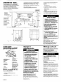
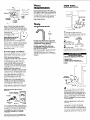
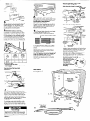
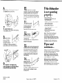
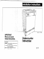
I
IMPORTANT:
Read and save
these instructions.
IMPORTANT:
Installer: Leave Installation Instructions with
the homeowner,
Homeowner:
Keep Installation Instructions
for future reference.
Save Installation Instructions for local
inspector’s use.
.I
w
Part No. 3373986
Undercounter
Dishwasher
5(43
Before you start...
Proper electrical,
drain and water supply
lines must be available
or must be installed
as specified within shaded area. Wiring
should not cross in front of motor or
dishwasher legs. See Electrical, Water and
Drain requirements.
Proper installation is your responsibility.
Make sure you have everything
necessary
for correct installation.
It is the personal
responsibility
and obligation
of the
customer to contact 6 qualified installer to
as-sure that electrical
and plumblng
installations meet all national and local
codes and ordinances.
Electrical
ground is
required.
See “Electrical
requirements.”
IMPORTANT: Observe all governing
codes and ordinances.
cord or kink
power supply
cable between
dishwasher and
cabinet.
max.
The unshaded area must be free
of plpes or wlres.
Electrlcal outlet must be Installed
In an adjacent
cabinet.
A
i
1
f
I
Grommet
required for
electrlcal
cable
or power supply
cord hole cut In
a metal
cabinet.
/’
,
/ -/
0
c
24’
.‘I I-underslde
0‘
--------
9
4’
----a---
2-l/2’/ --
4
;lo.
J- p
10’
4
\
_
-L
‘\‘,
-\
f
2-112”
-5
2’
k5’Y
I\
L
l
l
l
l
Electrical Shock Hazard
It is the personal responsibility
and
obligation
of the customer to
contact a qualified electrician
to
assure that the electrical
installation
is adequate
and is in conformance
with the National Electrical Code,
ANSI/NFPA 70 - latest edition’ and
all local codes and ordinances.
Failure to follow these instructions
could result in electrical
shock or
other personal injury.
Electrical wiring and components
must not contact any plumbing
material or drain hose.
Cabinet opening must completely
enclose sides, top and back of
dishwasher.
Failure to do so may result in personal
injury from exposed wiring.
Personal Injury/Product
Damage
Hazard
Avoid opening dishwasher door
before dishwasher is installed.
Dishwasher, before it is installed, may
tip over when door is opened,
resulting in personal injury or product
damage.
l
l
“\
b'
’
l
l
Corner location
2’ mln. door to
cabinet or wall. -
Cut openlngs Water Ilne: l/2’ hole
or larger.
Draln Ilne: 1-l/2’ hole
or larger.
Power supply cord: 1-l/2’
hole.
Direct wlrlng: 3/4’ hole.
Check location where dishwasher will
be installed. The location should
provide:
Easy access to water, electricity
and
drainage
lines.
Convenient
loading - the best
position Is left or right of kitchen sink.
Opening that is square for proper
dishwasher operation
and
appearance.
Cabinet front that is perpendicular
to floor.
Protection so that water inlet valve
and drain cannot freeze.
l/4’ minimum clearance
between
motor and flooring to prevent motor
from overheating.
"%L
2’
l
+--
24’ depth
-
-
23-718’ width +
t
B-7/8’
mln.
helght
Coples of the standards
obtained
from:
Figure
2
‘Natlonal
Fire Protectlon
Bat?erymarch
Park
Qulncy, Massachusetts
-
listed may be
Assoclatlon
02269
Read and follow the “Electrical
requirements”,
” Water requirements”
and “Drain requirements”
sections
before installing dishwasher.
Tools and
materSah needed
for ins talla tion:
Electrical
requirements
Wiring methods
Pick one method to follow, depending
upon your dishwasher and local codes.
Direct wire method
(cdble connecting
dishwasher
to a junction box).
a
Electrical Shock Hazard
Electrical ground is required on this
appliance.
lf cold water pipe is interrupted
by
plastic, non-metallic
gaskets or
other insulating materials Do Not
use for grounding.
Do Not ground to gas pipe.
Do Not modify the power supply
cord plug. If it does not fit the outlet,
have a proper outlet installed by a
qualified electrician.
Do Not use an extension cord with
this appliance.
Do Not have a fuse in the neutral or
grounding
circuit. A fuse in the
neutral or grounding
circuit could
result in an electrical
shock.
Check with a qualified electrician
if
you are in doubt as to whether the
appliance
is properly grounded.
Failure to follow these instructions
could result in serious injury or death.
l
l
l
l
l
l
l
l
l
l
l
l
l
electric
drill
l
PhillIDs screwdrlver
l
2 adjustable
wrenches
pliers
measurlng tape
flat-blade
screwdrlver
plpe wrench
keyhole saw
tubing cutter
shown)
pipe-Joint
compound
l
.
(not
.
wlre strip er and
utlllty knl Pe
5/16’ and l/4’
nut driver or hex
socket
3 twlst-on wlre
connectors
for 16gauge wire (not
shown)
90” elbow wlth 318’
N.P.T. external
threads on one end.
The size of the other
end must fit your
water supply Ilne.
(not shown)
gloves (not shown)
Parts supplied for
installatfon:
l
2 draln hose clamps
l
2, No.- 10 x l/2’
Phllllps-head
screws
* draln hose
Remove parts from bag. Check
parts were supplied.
that all
l
l
l
l
If codes permit and a separate grounding wire is used, it is recommended
that
a qualified electrician
determine that the
grounding
path is adequate.
A 120-volt, 60-Hz, AC-only, 15- or 20ampere, fused electrical supply is
required. Tlme-delay fuse or circuit
breaker is recommended.
It is
recommended
that a separate circuit
serving only this appliance
be provided.
The dishwasher must be connected
copper wire only.
Panel A
with
Electrical Shock Hazard
Disconnect
electrical
power at the
service panel (fuse box or circuit
breaker box).
Failure to do so could result in serious
injury or death.
Recommended
method -
grounding
1. Disconnect
power supply.
2. Run flexible, armored or non-metallic
sheathed,
copper cable (with grounding wire) from fused disconnect,
circuit
breaker or junction box through the 3/4”
cabinet hole to the dishwasher location.
The cable must extend 24” from the
back wall.
The hole cut through a wood cabinet
should be sanded until smooth.
The hole cut through a metal cabinet
must be covered with a grommet (Part
No. 302797), available
from your local
dealer or parts supplier.
A U.L.-listed strain relief or conduit connector must be installed at each end of
the power supply cable (at the dishwasher and at the junction box). Wire
sizes (COPPER WIRE ONLY) must conform
with the rating of the dishwasher.
Water
requirements
power
suPPlY
cable
Now start...
With dishwasher
The hot water line to the dishwasher
must provide between
15 - 120 psi water
pressure. The hot water heater should be
set to deliver 140°F water temperature
to
the dishwasher for best results.
Use 3/8’ minlmum 0-D. copper tubing or
l/2’ mlnlmum plastic tubing inlet line.
Dishwasher inlet valve has 3/8’ N.P.T.
internal pipe thread.
U.L.-llsted
straln relief
or conduit
connector
3. Remove the dishwasher terminal box
cover. Connect the white and black
wires of the power supply cable to the
white and black leads in the terminal box
with twist-on wire connectors.
(See Figure
3.1
4. Loosen the front nut on
the grounding
connection
stud located
on the back of the
“-sZ:”
terminal box. Do Not
loosen the rear nut on the
,,
grounding
connection
”
0
stud. Form the bare
grounding
wire into a U-shaped hook.
Wrap the grounding
wire hook around
the grounding
connection
stud between
the two nuts on the stud. Securely tighten
the front nut over the grounding
wire.
5. Check that strain relief or conduit
connector
screws are tight. Replace
terminal box cover.
B.
Power supply cord method
(connecting
dishwasher
to outlet).
Local codes may permit the use of a U-L.listed, flexible, three-conductor,
power
supply cord terminated
with a threeprong, grounding-type
plug.
It is recommended
that cord kit (Part No.
4317824), available
at your local dealer
or parts supplier, be used. Follow the
instructions packaged
with the power
supply cord kit. If the cord kit is not
available
locally, the flexible cord used
must be a U.L.-listed, three-conductor,
1&gauge
cord that meets the National
Electrical Code, ANSI/NFPA 70 - latest
edition’ and local codes and
ordinances.
The length of the cord must
not exceed six feet. It must be routed so
it does not touch the dishwasher motor
or the lower portion of the dishwasher
tub. A strain relief (Part No. 596171),
available
at your local dealer or parts
supplier, or a similar part must be used to
secure the flexible cord to the
dishwasher frame or terminal box. The
flexible cord must be plugged into a
mating, 3-prong, grounding-type
wall
receptacle,
grounded
in accordance
with the National Electrical Code
ANSI/NFPA 70 - latest edition,* and all
local codes and ordinances.
Follow the
instructions packaged
with the flexible
cord.
grounding
j-prong,
groundlnghe
, wall receptacle
power supply
cord
Figure 4
For your personal safety, this appliance
must be grounded.
A power supply cord
having a 3-prong grounding
plug must
be used. It is the personal responsibility
and obligation
of the customer to have
a properly grounded,
3-prong wall
receptacle
installed by a qualified
electriclan.
The receptacle
should be installed
the rear or side wall of the cabinet
to the dishwasher opening.
------IY-1
cabinet
wall
alternate waterline locatlons
--I
water
supply
pipe
6’
Figure 3
Recommended
method
in kitchen.
on
next
AJ!t!$j
Drain
requirements
^
4
4’
2-l/2’
t
20’ mln.
to floor
The drain hose MUST have a high drain
loop, 20’ minimum ABOVE FLOOR, to
prevent backflow or water siphoning out
of dishwasher during operation.
NOTE: An air gap MUST BE USED in
the high drain loop if the drain hose
is connected
to house plumbing lower
than 20’ above the floor.
Drain hose, supplied, meets AHAM DW- 1
test standards, Cut l-l /2” hole in
cabinet wall for drain hose. Additional
drain line (a minimum of l/2’ I.D. and no
longer than 20 feet) can be used if
needed.
10’
2’
5’
1
n Rough
in water line to the
dishwasher cabinet opening using one
of the routing methods shown. Cut l/2’
or larger hole in cabinet wall for
water line.
2
n
Install a
shutoff valve in the
water Ilne where it
can be easily used.
3
= Flush water
line into a bucket to get rid of any
particles that may clog inlet valve.
shutoff valve to the “OFF” position.
Turn
Electrical Shock Hazard
Disconnect
electrical
power at the
service panel (fuse box or circuit
breaker box).
Failure to do so could result in
electrical
shock or other personal
lnlurv.
alternate
electrlcal
wlrlna Iocatlon
4
electrlcal
wlrlng
\I?
6’
n Cut a l-l /2’ maximum
hole for
power supply cord or a 3/4’ hole for
direct wiring in the cabinet or floor for
the electrical wiring to pass through. If
this hole is cut in a wood cabinet, sand
the hole until it is smooth. If the hole is
cut in a metal cabinet, the hole must
be covered by a grommet (Part No.
302797), available
at your local dealer
or parts supplier.
Install wall receptacle
on rear or side
wall of a cabinet next to dishwasher
opening.
Install a 3/4’ U. L.-listed conduit
connector
to connect the flexible
armored or non-metallic
sheathed,
copper cable (with grounding
wire) to
the fused disconnect,
circuit breaker or
junction box. Run the cable through the
hole in the cabinet opening. The cable
should extend 24’ from the back wall.
----
Recommended
drain hose
connection
methods:
Drain hose to air gap to waste tee.
alr-gap klt (Part
No. 300096)
toe p
5
Remove the 4 screws attaching
access panel and toe panel to dishwasher using a l/4’ hex socket, nut
driver or Phillips screwdriver.
Remove
access panel and toe panel.
n
6
l Measure
height of cabinet
opening from the front edge of the
underside of cabinet opening to floor.
Check chart for that height opening.
Put the wheels in the required position.
The dishwasher should be installed as
level as possible from front to back.
Loosen and then turn front levelers the
number of times indicated
in the char-t.
8 w Latch dishwasher door. Push
dishwasher into place, sliding drain hose
through hole cut in cabinet opening.
Do not pinch power supply cord or kink
power supply cable between
dishwasher and cabinet.
Check that front leveling legs are firmly
against the floor. Align dishwasher door
with cabinet doors, so that spacing is
the same on both sides.
9
m Connect drain hose to an air gap
or waste tee using one of the
recommended
or alternate methods.
Cut hose connector
?w
spriig-
20’ mlnlmum
clearance
to
tloor
1
g
.ZKps
Entry must be
above trap.
$
Drain hose to air gap to disposer.
0
rubber
connector
ylr-gap klt (Part No.
00096) v,
l-8
sprtng\
to fit, It needed.
@wJ-lm
If connecting
drain hose to an air gap
or waste tee, cut end of drain hose as
shown.
Secure drain hose with screw-type
or
spring-type
hose clamp (clamp type
varies with models).
Do Not cut drain hose when connecting
to a 7/8’ disposer connector.
Knock out
plug from disposer inlet. Secure drain
hose with hose clamp provided.
DO NOT cut ribbed section to shorten
drain hose.
34-l/18”
2
6
34-5/l 6”
3
3
34-l 12”
4
0
For addltlonal
height:
1. Add shims under the wheels.
2. Turn front levelers (each turn Is approximately
l/16’ In height).
You may have this type drain
connector...
Numbers
correspond
to steps.
7
n Put spring-type
drain hose clamp
over connector.
Push drain hose onto
connector.
Use pliers to open clamp and
slide clamp over drain hose and connector. Check that drain hose is secure.
If screw-type
clamp is used instead of
spring-type clamp, use a 5/l 6’ nut driver
to tighten drain hose securely to
connector.
To minimize noise and vibration, route
drain hose to avoid contact with door
springs, motor, water line, cabinet or
flooring. Do Not run drain hose over top
of tub.
Floor Damage
Tilt dishwasher backwards
on wheels
when moving across floor.
Failure to do so may cause damage
to floor covering.
Panel C
Drain hose
Entry must be
above trap.
I
I
Install air gap according
to kit instructions.
If other brands of air gaps are used, they
should be checked
to make sure they
allow for the same air flow.
Connect the air gap to a waste tee’ or
disposer using a rubber connector*.
Most disposers have 7/8’ connectors
or
special connectors
are available
at
plumbing supply houses. Be
sure to remove the
disposer plug befor
connecting
the
drain hose. You
may need to
remove disposer
from sink to remove
the plug.
Alternate drain hose
connection
methods:
Drain hose to waste tee.
Top mounting brackets attached
underside of countertoD.
,~~~~~~t~r
Door and
access and
toe panels
not shown.
18
m Turn bn electric suoolv. Start
dishwasher and allow it to cb~blete
a
cycle. Check that dishwasher is working
properly and that there are no water
leaks.
No.10 x l/2’
abbve
trap.
H
If local plumbing codes permit,
dishwasher drain hose may be
connected
directly to waste tee”. The
waste tee connection
MUST be made
ahead of the trap and a minimum of 20
inches above the floor.
Drain hose to disposer.
Ad
ut ho
ctor.
Do Not
drop
screws
Into tub.
, hyJJ-
III
II I
IL
H Open dishwasher door and
remove all shipping materials. Remove
bottom rack. Place a newspaper,
large
sheet of paper or a towel over bottom
of dishwasher to prevent screws or other
items from entering the pump area
when securing dishwasher to
countertop.
Personal
If local plumbing codes permit,
dishwasher drain hose may be
connected
directly to disposer. Most
disposers have 7/8” connectors
or
special connectors
are available
at
plumbing supply
houses. Be sure to
remove the
disposer plug
before connecting
the drain hose.
You may need to
remove disposer
from sink to remove
the plug.
‘All parts are available
through your dealer
local hardware
or plumbing store.
or
Injury/Product
Damage
Hazard
l The dishwasher
must be secured to
the countertop
to keep it from tilting
when door is open.
l
Do Not drop screws in dishwasher
tub. If screws should fall into pump,
pump and motor damage may
occur.
Failure to follow these instructions
may result in personal injury or
product damage.
‘I
-
panel
19
n
Replace the access panel
and toe panel. The toe panel must be
positioned to contact floor.
13
n Secure
dishwasher to countertop with two, No.-10 x l/2” Phillips-head
screws from parts bag. You MUST secure
dishwasher to keep it from tilting when
door is opened or closed. Do Not drop
screws in dishwasher tub. Remove
paper from bottom of dishwasher.
Equally
spaced
L
Inlet valve
\
\
14 \mrln
@I
w Open door approximatelv
3”
and check’for equal $&zing
betw’een
inner door and tub sides. If necessary,
loosen screws that fasten dishwasher to
countertop
and shift tub. Tighten screws.
10
n
Connect water pipe or tubing
directly to water inlet valve..Do Not runpipe or tubing across front of motor or
dishwasher legs. Turn on water supply
and check for leaks.
11
HCheck electrical
requirements.
Be sure you have correct electrical
supply and recommended
grounding
method. See Panels A and B for $roper
connecKon.
15
n
Check door for orooer
operation.
Open door to’a 4’5” angle. If
properly adjusted, door should stay in
this position. If door shuts or falls open,
close door and adjust both door springs
by moving spring ends to different holes
in base.
16
H If changing
color of door and
access panel or installing custom
panels, follow the ‘To change door
panel color” and “To change access
panel color” instructions, Panel E and
back cover.
Congratulations!
You have just finished installing
your new undercounter
dish washer. Keep Installation
Instructions available
for easy
reference.
I
Product Damage
Do Not solder within 6” of plastic
water inlet valves.
Failure to follow this instruction could
result in product damage.
Panel D
toe pbnel
20
20’ minimum
clearance
to
floor
water
17
m Check that all parts have
been installed and no steps were
skipped. Check that you have all the
tools you started with.
n Take a few
minutes to read the
Use and Care Guide to fully understand
your new dishwasher.
To change door
Dane1 color
This panel is
narrower
than access
panel.
:OTE: The opposite side of the door
color panel is a different color.
File or sand
edges of wood
panel to avold
sllvers.
Important:
Run fingers along
bottom 6f retainer to ctieck thatretainer is lower than the lower door
frame.
n
Personal
Wear gloves and
carefully.
Cut metal edges
injury or damage
Injury Hazard
handle panels
may cause personal
to other materials.
1
aside.
2
n Slide panel(s)
down to clear
console. Use both
hands to bow top and
bottom edge of door
panel(s). Remove
panel(s) from door.
Do Not remove
spacer.
3
To change access
color panel
(For models
n Push up at
each end of
retainer at
bottom of door
panel. Then pull
retainer toward you. Set retainer
clear access panel
when door Is In
open posltlon.
Injury Hazard
handle panels
Heavy-duty
door springs must be used if
custom door panel weighs more than 4
pounds. Heavy-duty
Door Springs Kit,
Part No. 43 18050, Is available
from your
local dealer or parts supplier. Maximum
door weight is 8 pounds.
may cause personal
to other materials.
1
Wood access
This panel
/d-
n
All edges
.-
lower door
frame
6
w Lift up and hold panel(s) and
spacer l/4’ above lower door frame.
2
n Line up
edges of top trim
with sides of
access panel
frame. Tilt back of
trim down and slide into place. Snap
front of trim down to cover top edge of
access panel.
3 m Push up at
each end of retainer
at bottom of door
panel. Then pull
retainer toward you. Set retainer
To install
customized wood
panels in door and
over lower edge
of door frame
while holding
door panel(s)
and spacer up.
A door panel thicker than 7/32’,
requires routing the top and bottom to a
7132’ thickness.
An access panel thicker than 7/32’,
requires routing all four edges to a 7/32’.
It is recommended
that a cabinetmaker cut the customized
panels
because of the precise cuts required.
(See Figures 5 and 6.)
Personal
Wear gloves and
carefully.
Cut metal edges
injury or damage
aside
Injury Hazard
handle panels
may cause personal
to other materials.
4
I Slide panel(s) down
to clear console. Use both
hands to bow top and
bottom edges of color
door panel(s). Save color
panel(s) and spacer for
future use.
,>
),
’
I’I
I’
‘1~
r;
2
:<, ./,;
,--‘! /!. ‘.,
Ins
be
sld
Wood door panel
Cut accurately
for a snug fit between
door side frames. Note: Custom panel
fits between, Not inside frame.
/
panel flts
between,
not
Inslde, door frame
n Insert top of wood
door panel
between sides of door frame about 3”
below console. Rotate wood door panel
down against dishwasher door. Slide top
edge of wood door panel under bottom
edge of console. Press lower portion of
wood door panel in place between
sides of door frame.
5
8 w Snap
retainer down
into place. Push down firmly along entire
length of retainer to make sure retainer is
secure. Slide door panel(s) down.
Figure 6
n
File or sand edges of wood panels
to avoid slivers.
Dishwasher is subject to some humidity.
Cover both sides and edges of wood
panels with moisture-resistant
sealer.
Dishwasher do: panel and access
panel (if model is so equipped)
can be
customized
to match wood cabinets. A
standard
l/4’ (7/32’ actual thickness)
wood panel can be used as is for
customizing
the door and access
panels.
.
,7/32’thlck
1 . Cut wood door and access panels
using specified dimensions. Make sure
wood grain direction matches cabinet
wood grain.
colorT
Panel E
routed to 7/32’ thickness.
1
4
n
Push in on
door panel(s) near
the too and slide
panelks) and
spacer up inside
bottom of control
console.
AYllL
1
3
n
Bow door panel(s)
and insert other side of
door panel(s) into door
frame.
lower‘door
23-S/16’
Top view
w With
desired color
facing out, bow
access panel
and insert into
access Dane1
frame. Slide panel down into groove
along bottom of access panel frame.
4
\
panel
is wider than door panel.
4-7116’
Carefully
slide color
access panel
upwards and
remove. Do Not
remove spacer.
With desired
color facing out,
insert one side of
door panel(s) into
one side of door
frame.
b
Figure 5
n Push up
with thumbs’on
each end of
access panel
top trim to
unsnaD trim.
Remove top trim and set it aside.
n
e
bc>ttom
8edge
so equipped)
Personal
Wear gloves and
carefully.
Cut metal edges
injury or damage
2
,,’
w
+4
;‘1:32’
6
Lift up and hold wood door panel
l/4” above lower door frame.
n
wood
pan-
I
10
If the dishwasher
is not operating
properly.. .
Check door for oroper
operation.
Open door to a 45’ angle. If
properly adjusted, door should stay in
this position. If door shuts or falls open,
close door and adjust both door springs
by moving spring ends to different holes
in base.
n
11
7
/ w Insert retainer over
lower edge of door frame while holding
wood door panel up.
8 n Snap retainer
down into place.
Push down firmly
along entire length
of retainer to make sure retainer is
secure. Slide wood door panel down.
n Push up with
thumbs on each end
cs,
of access panel top
6
trim to unsnap trim.
Remove top trim and set it aside.
12
m Carefully
slide color access
panel and spacer
upwards and
remove. Save color access
spacer for future use.
panel
9
Part No. 3373986
01993
and
13
m Insert wood access panel into
access panel frame. Slide panel down
into groove along bottom of access
panel frame. It may be necessary to
remove top mounting screws and tilt
access panel forward to install some
wood panels.
tine up
edges of top trim
with sides of access
panel frame. Tilt
2IY
back of trim down &
and slide into place. Snap front of trim
down to cover top edge of wood
access panel,
n
n Important:
Run fingers along
bottom of retainer to check that retainer
is lower that the lower door frame.
\
Benton
Harbor,
Ml 49022
Check these points:
l Is the door closed
tightly and
latched securely?
l Has the cycle
been set correctly to
start the dishwasher?
l Is the water
turned on?
l Has a house
fuse blown or circuit
breaker tripped?
l Has electrical
power been
interrupted?
Note: If the motor has stopped
because of overload,
it will
automatically
reset itself within a few
minutes. If after checking
these points
the dishwasher still does not run or
complete
a cycle, call for service.
If you need
assistance...
Check your Use and Care Guide for a
toll-free number to call or call the dealer
from whom you purchased
this
appliance.
The dealer Is listed in the
Yellow Pages of your phone directory
under “Appliances
- Major.”
When you call, you will need the
dishwasher model number and serial
number. Both numbers are on the
serial/rating
plate, which can be found
on the front frame behind the door.
Printed in U.S.A.