1
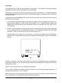
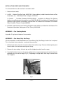
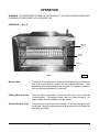
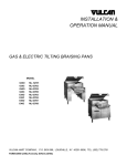
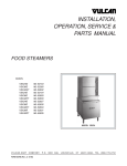
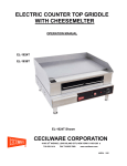
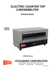
INSTALLATION &
OPERATION MANUAL
MODEL CMR34 GAS CHEESEMELTER
ML-52198
VULCAN-HART
COMPANY,
FORM 30805, Rev. A (8-95)
P.O.
BOX
696,
LOUISVILLE,
KY
40201-0696,
TEL. (502) 7 7 8 - 2 7 9 1
IMPORTANT FOR YOUR SAFETY
THIS MANUAL HAS BEEN PREPARED FOR PERSONNEL QUALIFIED TO INSTALL GAS
EQUIPMENT, WHO SHOULD PERFORM THE INITIAL FIELD START-UP AND
ADJUSTMENTS OF THE EQUIPMENT COVERED BY THIS MANUAL.
POST IN A PROMINENT LOCATION THE INSTRUCTIONS TO BE FOLLOWED IN THE
EVENT THE SMELL OF GAS IS DETECTED. THIS INFORMATION CAN BE OBTAINED
FROM THE LOCAL GAS SUPPLIER.
IMPORTANT
IN THE EVENT A GAS ODOR IS DETECTED, SHUT
DOWN UNITS AT MAIN SHUTOFF VALVE AND
CONTACT THE LOCAL GAS COMPANY OR GAS
SUPPLIER FOR SERVICE.
FOR YOUR SAFETY
DO NOT STORE OR USE GASOLINE OR OTHER
FLAMMABLE VAPORS OR LIQUIDS IN THE
VICINITY OF THIS OR ANY OTHER APPLIANCE.
WARNING
IMPROPER INSTALLATION, ADJUSTMENT,
ALTERATION, SERVICE OR MAINTENANCE CAN
CAUSE PROPERTY DAMAGE, INJURY OR DEATH.
READ THE INSTALLATION, OPERATING AND
MAINTENANCE INSTRUCTIONS THOROUGHLY
BEFORE INSTALLING OR SERVICING THIS
EQUIPMENT.
IN THE EVENT OF A POWER FAILURE, DO NOT
ATTEMPT TO OPERATE THIS DEVICE.
—2—
Installation, Operation and Care of
MODEL CMR34 GAS CHEESEMELTER
KEEP THIS MANUAL FOR FUTURE REFERENCE
GENERAL
Your Vulcan-Hart Gas Cheesemelter is suitable for use in restaurant, commercial or institutional
kitchens. The cheesemelter is produced with quality workmanship and material. Proper installation,
usage and maintenance of your cheesemelter will result in many years of satisfactory performance.
Vulcan-Hart Company suggests that you thoroughly read this entire manual and carefully follow all of
the instructions provided.
CMR34 Cheesemelter Broilers are available in two styles:
1. Elevated Model — mounts over Heavy Duty Gas Range or Gas Restaurant Range (34" width
minimum).
2. Free Standing Model — mounts on a non-combustible countertop with a 4" base stand.
INSTALLATION
Before installing, verify that the type of gas (natural or propane) agrees with the data plate on the body
top of the cheesemelter.
UNPACKING
The cheesemelter was carefully inspected before leaving the factory. The transportation company
assumes full responsibility for safe delivery upon acceptance of the shipment. Immediately after
unpacking, check for possible shipping damage. If the cheesemelter is found to be damaged, save the
packaging material and contact the carrier within 15 days of delivery.
—3—
LOCATION
Do not obstruct the air flow into and around the cheesemelter. This air flow is necessary for proper
combustion of gases and for ventilation of the cheesemelter.
Do not obstruct the flow of flue gases from the flue duct of the cheesemelter. It is recommended that
the flue gases be ventilated to the outside of the building through a ventilation system installed by
qualified personnel.
If mounted over a range equipped with casters, the minimum width of the range is 60 inches and the
following restrictions apply:
1. The installation shall be made with a connector that complies with the Standard for Connectors for
Movable Gas Appliances, ANSI Z21.69 (latest edition), and a quick-disconnect device that
complies with the Standard for Quick-Disconnect Devices for Use With Gas Fuel, ANSI Z21.41
(latest edition).
2. Provide a restraining device for the gas line to limit the movement of the range without depending
on the connector and the quick-disconnect device or its associated piping to limit the range
movement. Attach the strain relief to the rear of the range (Fig. 1).
If disconnection of the strain relief is necessary, turn off the gas supply before disconnection.
Reconnect this restraint before turning the gas supply on and returning the range to its installation
position.
CONNECT GAS LINE
STRAIN
RELIEF HERE
PL-51219
Fig. 1
Maintain a minimum 6" clearance at the sides and rear next to combustible and non-combustible
construction. Maintain an 18" clearance from the end of the cheesemelter flue vent to the filters of the
hood venting system.
Keep the area free and clear of all combustible substances.
The installation location must allow adequate clearances for servicing and proper operation. A
minimum front clearance of 18" is required.
Make sure there are no cross currents within the kitchen (such as wall-type fans, open windows next
to the cheesemelter, or fans blowing directly on the cheesemelter).
—4—
INSTALLATION CODES AND STANDARDS
The cheesemelter must be installed in accordance with:
1. State and local codes.
2. In USA . . . National Fuel Gas Code, ANSI Z223.1 (latest edition) available from the American Gas
Association, Inc., 1515 Wilson Blvd., Arlington, VA 22209.
In Canada . . . Canadian Standard CAN/CGA-B149.1 Installation for Natural Gas Burning
Appliances and Equipment (latest edition), and CAN/CGA-B149.2 Installation for Propane Burning
Appliances and Equipment (latest edition), available from The Canadian Gas Association, 55 Scarsdale
Road, Don Mills, Ontario, Canada M3B2R3.
3. NFPA 96, Vapor Removal from Cooking Equipment (latest edition), available from the National Fire
Protection Association, Batterymarch Park, Quincy, MA 02269.
ASSEMBLY — Free Standing Models
Assemble 4" leg base to bottom of cheesemelter.
ASSEMBLY — Over Heavy Duty Gas Range
If the cheesemelter is to be mounted over a Vulcan Heavy Duty Gas Range, a back riser is required.
This is furnished when ordered as an elevated cheesemelter.
1. With the back down, place the riser on the floor in front of the range. Remove the backsplash panel
from the back riser and two mounting bolts at top.
2. Remove the top castings, the back top and the shipping brackets from the range.
3. Carefully lift the back riser over the range, guiding the riser supports (or bayonets) into the channels
provided at the rear of the range (Fig. 2). Depending on range width, there may be two or three
riser supports.
RISER SUPPORT
CHANNEL
RANGE
PL-40719-1
Fig. 2
—5—
4. Replace back top(s) and top castings on range.
5. After unpacking, remove the rack, drip pan and drip pan insert from the cheesemelter.
6. Make sure the mounting brackets are firmly attached to the top of the cheesemelter.
Carefully lift the cheesemelter so that the cheesemelter support brackets are approximately one
inch above the flue outlet of the back riser. Carefully guide the mounting brackets attached to the
cheesemelter over the mounting brackets on the top of the back riser. Lower the cheesemelter so
that all four brackets, two on top and two at the bottom, are supporting the cheesemelter.
7. Reinstall the two mounting bolts at top of the back riser (Fig's. 3 and 4).
MOUNTING BOLTS
BOTTOM SUPPORT BRACKET
BOTTOM FRAME OF BROILER
PL-40720-1
PL-40721-1
Fig. 4
Fig. 3
8. Attach the backsplash panel to the back riser. Attach shelf to back riser if included.
ASSEMBLY — Over Gas Restaurant Range
If the cheesemelter is to be mounted over a Vulcan Gas Restaurant Range, a back riser is required
(furnished when ordered as an elevated cheesemelter).
1. Mount back riser onto Gas Restaurant Range so riser supports slide into the channels on the back
of the range (similar to Heavy Duty Range, Fig. 2). Attach screws to channels on rear of range.
Mounting brackets for cheesemelter and support beam are assembled onto the back riser at the
factory. Remove the two mounting bolts from top of support brackets on back riser.
2. Assemble two support brackets to the top rear corners of the cheesemelter. Remove four bolts on
each corner; install brackets under bolts (Fig. 5).
3. Remove bottom cover of cheesemelter (8 screws).
4. Carefully lift the cheesemelter so brackets fit over the rail (beam support) on top of the backsplash
and so the bottom of the cheesemelter is supported by the two bottom support brackets (Fig. 6).
—6—
TOP SUPPORT BRACKET
TOP
SUPPORT
BRACKETS
RAIL
PL-40722-1
PL-40723-1
Fig. 5
Fig. 6
5. Line up holes on top brackets. Attach self-tapping screw to each top bracket, and attach 3/8-16 bolt
to each top bracket. Bolt thread through weld-nut on rail (beam support).
6. Reassemble bottom cover on cheesemelter (8 screws).
7. Attach shelf to back riser if included.
GAS CONNECTIONS
CAUTION: All gas supply connections and any pipe joint compound used must be resistant to
the action of propane gases.
Codes require that a gas shutoff valve be installed in the gas line ahead of the cheesemelter.
Install the pressure regulator to the top gas connection. The arrow on the regulator indicates the
direction of the gas flow (Fig. 7).
The regulator must be installed within the tower in an upright position. If it is mounted in any other
position, the pressure must be reset (Fig. 8).
GAS CONNECTION
GAS PRESSURE
REGULATOR
GAS PRESSURE REGULATOR
IN UPRIGHT POSITION
PL-40724-1
PL-40725-1
Fig. 7
Fig. 8
—7—
Standard cheesemelters for use with natural gas are equipped with fixed orifices and a pressure
regulator with a preset outlet pressure of 6" W.C. (water column).
Standard cheesemelters for use with propane gas are equipped with fixed orifices and a pressure
regulator with a preset outlet pressure of 10" W.C.
Once the regulator is installed, connect to a 3/4" gas line.
WARNING: PRIOR TO LIGHTING, CHECK ALL JOINTS IN THE GAS SUPPLY LINE FOR LEAKS.
USE SOAP AND WATER SOLUTION. DO NOT USE AN OPEN FLAME.
After piping has been checked for leaks, all piping receiving gas should be fully purged to remove air.
TESTING THE GAS SUPPLY SYSTEM
When test pressures exceed 1/2 psig (3.45 kPa), the cheesemelter and its individual shutoff valve must
be disconnected from the gas supply piping system.
When testing pressures are 1/2 psig (3.45 kPa) or less, the cheesemelter must be isolated from the gas
supply system by closing its individual manual shutoff valve.
—8—
OPERATION
WARNING: THE CHEESEMELTER AND ITS PARTS ARE HOT. BE CAREFUL WHEN OPERATING,
CLEANING OR SERVICING THE CHEESEMELTER.
CONTROLS — (Fig. 9)
BURNER
VALVE
SLIDING
SHELVES
GREASE
PAN
Fig. 9
Burner Valve
PL-40733-1
— The burner valve regulates the flow of gas throughout the cheesemelter.
Gas flow is increased by turning the valve counterclockwise. After
preheating, the maximum output is not required. Turn the valve clockwise
until the desired performance is achieved.
Sliding Shelves (Rack) — There are four rack positions. Place the shelf on the rack needed for
"cheesemelting". For deeper, longer heat, use lower positions. For
thinner foods, or faster cooking, use top shelves.
Grease Pan (Drip Tray) — The grease pan collects grease and waste. Do not allow the grease pan
to overflow. Empty the grease pan when three-quarters full to reduce the
possibility of spillage.
—9—
LIGHTING THE PILOT LIGHT
1. Turn on the main gas supply.
2. Turn on the burner valve and purge air from the line. Turn the burner valve off, wait five minutes.
3. Using a taper, light the pilots (Fig. 10).
4. If the pilots fail to light, turn off the gas, wait five minutes and repeat Steps 1 through 3.
5. Turn burner valve on for ignition.
PILOT
PL-40734-1
Fig. 10
Nightly Shutdown
Turn off the burner valve. The pilot will remain lit.
Seasonal Shutdown
1. Turn off the burner valve.
2. Turn off the pilots.
3. Turn off the main gas supply.
PREHEATING
Place the rack in its highest position. Turn the burner valve knob completely counterclockwise and
preheat for 15 minutes.
RECIPE AND RACK ADJUSTMENT
Positioning the cheesemelter rack is an important factor in the desired product end results. Position
the rack farther away from the burners for thick casseroles and for melting cheese or butter to avoid
drying the product. Position the rack closer to the burners for bacon, toast and quick heating, but watch
carefully to avoid burning.
— 10 —
LOADING AND UNLOADING
Place the rack in the desired position. Pull the rack out for loading. Load as quickly as possible and
avoid spillage. Push the rack into place and cook for the appropriate time. Lower and pull the rack out
for unloading.
CLEANING
PermaFinish surfaces can be cleaned using a cloth with detergent solution. An occasional application
of silicone base auto polish will help maintain a "like new" appearance.
Stainless steel surfaces may be cleaned with a damp cloth. Stubborn soil can be removed with a
detergent solution.
Clean the rack and drip tray every day at nightly shutdown. Allow the cheesemelter to cool before
removing the rack and the drip tray for cleaning.
MAINTENANCE
WARNING: THE CHEESEMELTER AND ITS PARTS ARE HOT. BE CAREFUL WHEN OPERATING,
CLEANING OR SERVICING THE CHEESEMELTER.
VENT
Annually, after the cheesemelter is cool, check the flue and clear any obstructions.
SERVICE AND PARTS INFORMATION
To obtain service and parts information concerning the cheesemelters covered in this manual, contact
the Vulcan-Hart Service Depot in your area (refer to listing supplied with the cheesemelter), or VulcanHart Company Service Department at the address or phone number shown on the front cover of this
manual.
— 11 —
TROUBLESHOOTING
PROBLEM
POSSIBLE CAUSES
Uneven heating
Side burning
1. Temperature too low
2. Improper operation of cheesemelter
3. Fluctuating gas pressure
Too much top heat
1.
2.
3.
4.
Uneven heat side-to-side
1. Cheesemelter not level side-to-side
2. Cheesemelter burner improperly installed
Uneven heat front-to-back
Cheesemelter not level front-to-back
Dried out products
1. Melting time too long, or product too close to
burners
2. Over-rated (pressure too high or orifice(s)
too large)
Pilot outage
1. Pilot flame too low
2. Restriction in pilot orifice
Poor ignition
1.
2.
3.
4.
5.
FORM 30805, Rev. A (8-95)
— 12 —
Temperature too high
Faulty ventilation
Excessive heat input
Over-rated (pressure too high or orifice(s)
too large)
Insufficient gas input
Poor air-to-gas adjustment
Restriction in pilot orifice
Restriction in main burner ignition port
Pilot adjustment is incorrect
PRINTED IN U.S.A.