1
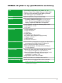
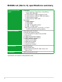
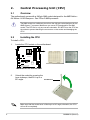
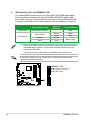
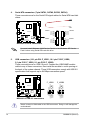
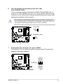
Motherboard
M2N68-LA
(Narra 3)
E3503
First Edition V1
October 2007
Contents
M2N68-LA (Narra 3) specifications summary........................................... iii
1.
Motherboard layout.......................................................................... 1
2.
Central Processing Unit (CPU)....................................................... 2
3.
4.
ii
2.1
Overview............................................................................. 2
2.2
Installing the CPU............................................................... 2
System memory............................................................................... 4
3.1
Memory configurations........................................................ 4
3.2
Installing a DIMM................................................................ 5
3.3
Removing a DIMM.............................................................. 5
Expansion slots .............................................................................. 6
4.1
PCI Express x16 slot........................................................... 6
4.2
PCI Express x1 slot............................................................. 6
4.3
PCI slots.............................................................................. 6
5.
Jumpers............................................................................................ 7
6.
Connectors....................................................................................... 9
6.1
Rear panel connectors........................................................ 9
6.2
Internal connectors............................................................11
M2N68-LA (Narra 3) specifications summary
CPU
Socket AM2 for AMD Athlon™ 64 / Athlon™ 64 X2 /
Sempron™ Rev F / Rev G 89W/ Phenom X4 9600 95W/
Phenom X2 65W and 89W (Socket-AM2+) processor
CPU FSB supports up to 2000MT/sec
Chipset
NVIDIA® MCP61P (co-layout with MCP68)
Memory
Dual-channel memory architecture
4 x 240-pin DIMM sockets support up to 8 GB non ECC 1.8V Dual Channel DDR2 800/667 SDRAM
memory (registered DIMMs are not supported)
Expansion slots
1 x PCI Express™ x16 slot for discrete graphics card
2 x PCI Express™ x1 slot
1 x PCI slots
Onboard I/O
1 x PS/2 keyboard port
1 x PS/2 mouse port
1 x VGA port
6 x Audio jacks
1 x RJ-45 10/100 LAN connector
10 x USB 2.0 ports (support hot-plug function)
1 x Floppy connector
1 x IDE connector
4 x SATA 3G connectors
Onboard IDE
NVIDIA® MCP61 embedded one channel Bus Master IDE
port supports Ultra DMA 66/100, PIO Mode 3/4
NVIDIA® MCP61 embedded 4 SATA ports
ATAPI IDE DVD-ROM, CD-ROM, CD-R, CD-RW and
LS-120 supported
Onboard audio
Supports HD audio codec that includes line-in, line-out
(7.1 channel), microphone-in, and S/PDIF-out
Audio Jack Presence Detection (all front and rear jacks)
must comply with Intel® High Definition audio
specification 1.0 section 7.4.2
Using Realtek® audio codec ALC888S
Onboard LAN
Realtek® RTL8201n 10/100Mbps Ethernet PHY
PC health monitoring
ASUS F8000 for CPU/System fan control, linear fan
speed control and CPU temperature monitoring
(continued on the next page)
iii
M2N68-LA (Narra 3) specifications summary
Front panel and back
panel
Front panel:
1 x 9-pin header for Power Button, Reset Button,
Power LED, HDD LED
2 x 9-pin header for USB front panel (4 ports)
2 x 4-pin header for USB mini PMD use (2 ports)
1 x 9-pin header for Audio
1 x 9-pin header for IEEE 1394
Back panel:
1 x PS/2 keyboard
1 x PS/2 mouse
1 x 15-pin VGA
2 x USB + RJ-45 LAN connector
2 x USB + 1 x IEEE 1394
Azalia 6 ports audio jack: 4 x Line-out, 1 x Line-in,
1 x Mic-in (with jack retasking support)
Onboard connector
24-pin ATX power connector
4-pin ATX 12V power connector
1 x Intel® HD audio front panel 2x5-pin header
1 x Front line-in
2 x USB front panel 9-pin headers
2 x USB front panel 4-pin headers
1 x IEEE 1394 9-pin header
1 x S/PDIF-out (for HDMI)
1 x HDMI 2x8-pin header
1 x CPU fan connector
1 x System fan connector
BIOS features
Award code base
4Mb SPI Serial Flash
HP BIOS with Enhanced ACPI, DMI, Green, PnP
Features Plus
Form factor
uATX form factor: 9.6” x 9.6”
*Specifications are subject to change without notice.
iv
1.
Motherboard layout
24.5cm (9.6in)
CPU_FAN
PS/2KBMS
T: Mouse
B: Keyboard
Super
I/O
Asus
F8000
M2N68-LA
RTL8201N
AUDIO
24.5cm (9.6in)
FLOPPY
ATXPOWER
DDR2 XMM3 (64 bit,240-pin module)
ATX_CPU
LAN+USB
DDR2 XMM4 (64 bit,240-pin module)
1394+USB
DDR2 XMM1 (64 bit,240-pin module)
VGA
Socket AM2
SPDIF_OUT
DDR2 XMM2 (64 bit,240-pin module)
SPDIF_OUT
CHASSIS_FAN1
F_LINE_IN
NVIDIA®
MCP61P
PCIE_X1_2
SATA4
SATA3
CR2032 3V
Lithium Cell
CMOS Power
PCIE_X1_1
BUZZER
SATA1
SATA2
ALC888
PRIMARY_IDE
PCIE_X16
BIOS
CLEAR CMOS
CLEAR P.W
F_AUDIO
PC2
agere
L-FW3227-100
F_1394
F_USB1
F_USB2
F_USB3
F_PANEL
F_USB4
M2N68-LA (Narra 3)
2.
Central Processing Unit (CPU)
2.1
Overview
The motherboard comes with a 940-pin AM2 socket designed for the AMD Athlon™
64/ Athlon™ 64 X2/Sempron™ Rev F/Rev G 89W processor.
The AM2 socket has a different pinout from the 940-pin socket designed for the
AMD Opteron™ processor. Make sure you use a CPU designed for the AM2
socket. The CPU fits in only one correct orientation. DO NOT force the CPU into
the socket to prevent bending the connectors on the socket and damaging the
CPU!
2.2
Installing the CPU
To install a CPU:
1.
Locate the CPU socket on the motherboard.
M2N68-LA
M2N68-LA CPU Socket AM2
2.
Unlock the socket by pressing the
lever sideways, then lift it up to a
90º angle.
Socket lever
Make sure that the socket lever is lifted up to a 90º angle; otherwise, the CPU
will not fit in completely.
M2N68-LA (Narra 3)
3.
Position the CPU above the socket
such that the CPU corner with the
gold triangle matches the socket
corner with a small triangle.
4.
Carefully insert the CPU into the
socket until it fits in place.
Gold triangle
Small triangle
5.
When the CPU is in place, push
down the socket lever to secure the
CPU. The lever clicks on the side tab
to indicate that it is locked.
6.
Install a CPU heatsink and fan
following the instructions that came
with the heatsink package.
M2N68-LA (Narra 3)
3.
System memory
The motherboard comes with four Double Data Rate 2 (DDR2) Dual Inline Memory
Modules (DIMM) sockets.
A DDR2 module has the same physical dimensions as a DDR DIMM but has a
240-pin footprint compared to the 184-pin DDR DIMM. DDR2 DIMMs are notched
differently to prevent installation on a DDR DIMM socket.
The following figure illustrates the location of the DDR2 DIMM sockets:
3.1
XMM4
XMM3
XMM2
M2N68-LA 240-pin DDR2 DIMM sockets
XMM1
M2N68-LA
Memory configurations
You may install 256 MB, 512 MB, and 1 GB DDR2 SDRAM DIMMs into the DIMM
sockets.
•
Always use identical (the same type and size) DDR2 DIMM pairs for dual
channel mode. For optimum compatibility, we recommend that you obtain
memory modules from the same vendor.
•
This motherboard does not support double-sided 16-bit DDR DIMMs.
M2N68-LA (Narra 3)
3.2
Installing a DIMM
Unplug the power supply before adding or removing DIMMs or other
system components. Failure to do so can cause severe damage to both the
motherboard and the components.
2
To install a DIMM:
1.
Unlock a DIMM socket by
pressing the retaining clips
outward.
2.
Align a DIMM on the socket
such that the notch on the DIMM
matches the break on the socket.
3.
3
DDR2 DIMM notch
1
1
Firmly insert the DIMM into the
socket until the retaining clips
snap back in place and the
DIMM is properly seated.
Unlocked retaining clip
3.3
•
A DDR2 DIMM is keyed with a notch so that it fits in only one direction. Do
not force a DIMM into a socket to avoid damaging the DIMM.
•
The DDR2 DIMM sockets do not support DDR DIMMs. DO not install DDR
DIMMs to the DDR2 DIMM sockets.
Removing a DIMM
To remove a DIMM:
1.
Support the DIMM lightly with
your fingers when pressing the
retaining clips. The DIMM might
get damaged when it flips out
with extra force.
2.
2
Simultaneously press the retaining
clips outward to unlock the DIMM.
1
1
DDR2 DIMM notch
Remove the DIMM from the socket.
M2N68-LA (Narra 3)
4.
Expansion slots
4.1
PCI Express x16 slot
This motherboard supports PCI
Express x16 graphic cards that comply
with the PCI Express specifications.
The figure shows a graphics card
installed on the PCI Express x16 slot.
4.2
PCI Express x1 slot
This motherboard supports PCI
Express x1 network cards, SCSI cards
and other cards that comply with the
PCI Express specifications. The figure
shows a network card installed on the
PCI Express x1 slot.
4.3
PCI slots
The PCI slots support cards such as
a LAN card, SCSI card, USB card,
and other cards that comply with PCI
specifications. The figure shows a LAN
card installed on a PCI slot.
M2N68-LA (Narra 3)
5.
1.
Jumpers
Clear RTC RAM (3-pin CLRTC)
This jumper allows you to clear the Real Time Clock (RTC) RAM in
CMOS. You can clear the CMOS memory of date, time, and system setup
parameters by erasing the CMOS RTC RAM data. The onboard button
cell battery powers the RAM data in CMOS, which include system setup
information such as system passwords.
To erase the RTC RAM:
1. Turn OFF the computer and unplug the power cord.
2. Remove the onboard battery.
3. Move the jumper cap from pins 2-3 (Normal) to pins 1-2 (Clear CMOS).
Keep the cap on pins 1-2 for about 5~10 seconds, then move the cap
back to pins 2-3.
4. Reinstall the battery.
5. Plug the power cord and turn ON the computer.
6. Hold down the <F1> key during the boot process and enter BIOS setup
to re-enter data.
Except when clearing the RTC RAM, never remove the cap on CLRTC jumper
default position. Removing the cap will cause system boot failure!
M2N68-LA
CLEAR CMOS
2
1
Clear CMOS
M2N68-LA Clear RTC RAM
M2N68-LA (Narra 3)
3
2
Normal
(Default)
2.
Clear password (3-pin CLRPW)
This jumper allows you to clear the password if you forgot your password.
To erase the password:
1. Turn OFF the computer and unplug the power cord.
2. Move the jumper cap from pins 2-3 (Normal) to pins 1-2 (Clear
Password).
3. Plug the power cord and turn ON the computer.
4. After the computer boots up, turn OFF the computer.
5. Move the jumper cap from pins 1-2 to pins 2-3.
6. Hold down the <F1> key during the boot process and enter BIOS setup
to verify that the password has been cleared.
M2N68-LA
CLEAR P.W
2
1
Clear Password
M2N68-LA Clear password setting
3
2
Normal
(Default)
M2N68-LA (Narra 3)
6.
Connectors
6.1
Rear panel connectors
1
2
3
4
5
6
7
8
9
10
13
12
11
1.
PS/2 mouse port (green). This port is for a PS/2 mouse.
2.
Coaxial S/PDIF Out port. This port connects an external audio output device
via a coaxial S/PDIF cable.
3.
IEEE 1394a port. This 6-pin IEEE 1394a port provieds high-speed
connectivity for audio/video devices, storage peripherals, PCs, or portable
devices.
4.
LAN (RJ-45) port. This port allows 10/100 connection to a Local Area
Network (LAN) through a network hub. Refer to the table below for the LAN
port LED indications.
LAN port LED indications
LINK LED
Status
Description
OFF
No link
GREEN
Linked
Status
OFF
ORANGE
ACT LED
Description
Not Transmitting
Transmitting
ACT
LED
LINK
LED
LAN port
5.
Side Speaker Out port (gray). This port connects to the side speakers in an
8-channel audio configuration.
6.
Rear Speaker Out port (black). This port connects to the rear speakers on a
4-channel, 6-channel, or 8-channel audio configuration.
7.
Center/Subwoofer port (yellow orange). This port connects the center/
subwoofer speakers.
8.
Line In port (light blue). This port connects the tape, CD, DVD player, or
other audio sources.
9.
Line Out port (lime). This port connects a headphone or a speaker. In 4channel, 6-channel, and 8-channel mode, the function of this port becomes
Front Speaker Out.
10. Microphone port (pink). This port connects a microphone.
M2N68-LA (Narra 3)
Refer to the audio configuration table for the function of the audio ports in 2, 4,
6, or 8-channel configuration.
Audio 2, 4, 6, or 8-channel configuration
Port
Light Blue
Lime
Pink
Orange
Black
Gray
Headset.
2-channel
Line In
Line Out
Mic In
–
–
–
4-channel
6-channel
8-channel
Line In
Front Speaker Out
Mic In
–
Rear Speaker Out
–
Line In
Front Speaker Out
Mic In
Center/Subwoofer
Rear Speaker Out
–
Line In
Front Speaker Out
Mic In
Center/Subwoofer
Rear Speaker Out
Side Speaker Out
11. USB 2.0 ports. These four 4-pin Universal Serial Bus (USB) ports are
available for connecting USB 2.0 devices.
12. VGA port. This 15-pin VGA port connects to a VGA monitor.
13. PS/2 keyboard port (purple). This port is for a PS/2 keyboard.
10
M2N68-LA (Narra 3)
6.2
Internal connectors
This section describes and illustrates the internal connectors on the motherboard.
1.
Floppy disk drive connector (34-1 pin FLOPPY)
This connector is for the provided floppy disk drive (FDD) signal cable. Insert
one end of the cable to this connector, then connect the other end to the
signal connector at the back of the floppy disk drive.
Pin 5 on the connector is removed to prevent incorrect cable connection when
using a FDD cable with a covered Pin 5.
FLOPPY
NOTE: Orient the red markings on
the floppy ribbon cable to PIN 1.
M2N68-LA
PIN 1
M2N68-LA Floppy disk drive connector
M2N68-LA (Narra 3)
11
2.
IDE connector (40-1 pin PRIMARY_IDE)
The onboard IDE connector is for the Ultra DMA 133/100/66 signal cable.
There are three connectors on each Ultra DMA 133/100/66 signal cable:
blue, black, and gray. Connect the blue connector to the motherboard’s IDE
connector, then select one of the following modes to configure your device.
Mode of
device(s)
Master
Slave
Master
Slave
Drive jumper setting
Single device
Cable-Select or Master
Cable-Select
Two devices
Master
Slave
Cable connector
Black
Black
Gray
Black or gray
•
Pin 20 on the IDE connector is removed to match the covered hole on the
Ultra DMA cable connector. This prevents incorrect insertion when you
connect the IDE cable.
•
Use the 80-conductor IDE cable for Ultra DMA 100/66 IDE devices.
If any device jumper is set as “Cable-Select,” make sure all other device
jumpers have the same setting.
PRIMARY_IDE
NOTE: Orient the red markings
(usually zigzag) on the IDE
ribbon cable to PIN 1.
M2N68-LA
M2N68-LA IDE connector
12
PIN 1
M2N68-LA (Narra 3)
3.
ATX power connectors (24-pin ATXPOWER, 4-pin ATX_CPU)
These connectors are for ATX power supply plugs. The power supply plugs
are designed to fit these connectors in only one orientation. Find the proper
orientation and push down firmly until the connectors completely fit.
ATX_CPU
GND
+12V DC
M2N68-LA
M2N68-LA ATX power connectors
ATXPOWER
GND
+12V DC +3 Volts
+12 Volts
+12 Volts
+5V Standby
Power OK
Ground
+5 Volts
Ground
+5 Volts
Ground
+3 Volts
+3 Volts
Ground
+5 Volts
+5 Volts
+5 Volts
-5 Volts
Ground
Ground
Ground
PSON#
Ground
-12 Volts
+3 Volts
•
Do not forget to connect the 4-pin ATX +12 V power plug; otherwise, the
system will not boot up.
•
Make sure that your ATX 12V power supply can provide 8A on the +12V
lead and at least 1A on the +5-volt standby lead (+5VSB). The minimum
recommended wattage is 230 W, or 300W for a fully configured system.
The system can become unstable and might experience difficulty powering
up if the power supply is inadequate.
•
Use of a PSU with a higher power output is recommended when
configuring a system with more power-consuming devices. The system
may become unstable or may not boot up if the power is inadequate.
M2N68-LA (Narra 3)
13
4.
Serial ATA connectors (7-pin SATA1, SATA2, SATA3, SATA4)
These connectors are for the Serial ATA signal cables for Serial ATA hard disk
drives.
SATA4
M2N68-LA
SATA1
M2N68-LA SATA connectors
GND
RSATA_TXP4
RSATA_TXN4
GND
RSATA_RXP4
RSATA_RXN4
GND
GND
RSATA_RXN3
RSATA_RXP3
GND
RSATA_TXN3
RSATA_TXP3
GND
GND
RSATA_TXP1
RSATA_TXN1
GND
RSATA_RXP1
RSATA_RXN1
GND
GND
RSATA_RXN2
RSATA_RXP2
GND
RSATA_TXN2
RSATA_TXP2
GND
SATA3
SATA2
You must install Windows® 2000 Service Pack 4 or the Windows® XP Service
Pack1 before using Serial ATA hard disk drive.
5.
USB connectors (10-1 pin P24 F_USB1, 10-1 pin P150 F_USB2,.
5-1 pin P151 F_USB1, 5-1 pin P152 F_USB2)
These connectors are for USB 2.0 ports. Connect the USB/GAME module
cable to any of these connectors, then install the module to a slot opening at
the back of the system chassis. These USB connectors comply with USB 2.0
specification that supports up to 480 Mbps connection speed.
F_USB1
USB+5V
USB_P5USB_P5+
GND
USB+5V
USB_P6USB_P6+
GND
NC
USB+5V
USB_P6USB_P6+
GND
NC
M2N68-LA USB 2.0 connectors
USB+5V
USB_P5USB_P5+
GND
M2N68-LA
F_USB2
Never connect a 1394 cable to the USB connectors. Doing so will damage the
motherboard!
14
M2N68-LA (Narra 3)
6.
CPU and Chassis fan connectors (3-pin CPU_FAN,.
3-pin CHASSIS_FAN1)
The fan connectors support cooling fans of 350mA~740mA (8.88W max.) or
a total of 1A~2.22A (26.64W max.) at +12V. Connect the fan cables to the fan
connectors on the motherboard, making sure that the black wire of each cable
matches the ground pin of the connector.
Do not forget to connect the fan cables to the fan connectors. Insufficient air
flow inside the system may damage the motherboard components. These are
not jumpers! DO NOT place jumper caps on the fan connectors.
CPU_FAN
Rotation
+12V
GND
M2N68-LA
CHASSIS_FAN1
GND
+12V
Rotation
M2N68-LA Fan connectors
7.
Front panel audio connector (10-1 pin F_AUDIO)
AUD_GND
AUD_VCC
AUD_RET_R
AUD_VCC
AUD_RET_L
This connector is for a chassis-mounted front panel audio I/O module that
supports Azalia audio standard.
M2N68-LA
F_AUDIO
M2N68-LA Front audio connector
M2N68-LA (Narra 3)
AUD_MIC1
AUD_MIC2
AUD_FPOUT_R
AUD_MIC_JD
AUD_FPOUT_L
PIN1
15
8.
Internal audio connector (4-pin F_LINE_IN)
This connector allows you to receive stereo audio input from sound sources
such as a CD-ROM, TV tuner, or MPEG card.
M2N68-LA
F_LINE_IN
M2N68-LA Internal audio connector
16
M2N68-LA (Narra 3)
9.
System panel connector (10-1 pin F_PANEL)
This connector supports several chassis-mounted functions.
PLED+
PLEDPWR
GND
PWR LED PWR BTN
M2N68-LA
HDLED+
HDLEDGround
Reset
NC
F_PANEL
M2N68-LA System panel connector
• HD LED RESET
System power LED (2-pin PLED)
This 2-pin connector is for the system power LED. Connect the chassis power
LED cable to this connector. The system power LED lights up when you turn
on the system power, and blinks when the system is in sleep mode.
•
Hard disk drive activity LED (2-pin HDLED)
This 2-pin connector is for the HDD Activity LED. Connect the HDD Activity
LED cable to this connector. The IDE LED lights up or flashes when data is
read from or written to the HDD.
•
ATX power button/soft-off button (2-pin PWR)
This connector is for the system power button. Pressing the power button
turns the system on or puts the system in sleep or soft-off mode depending
on the BIOS settings. Pressing the power switch for more than four seconds
while the system is ON turns the system OFF.
•
Reset button (2-pin RESET)
This 2-pin connector is for the chassis-mounted reset button for system
reboot without turning off the system power.
M2N68-LA (Narra 3)
17
18
M2N68-LA (Narra 3)