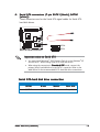
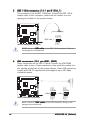
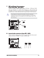
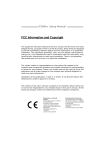
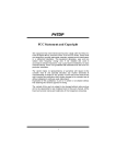
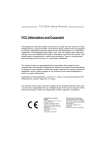
1
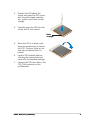
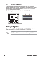
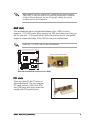
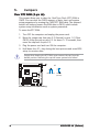
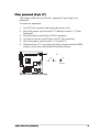
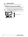
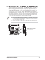
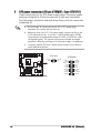
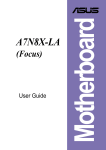
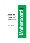
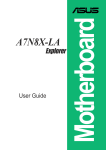
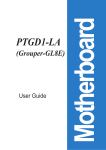
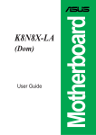
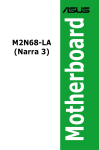
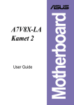
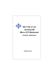
Motherboard
K8S-LA
(Salmon)
Contents
Checklist
K8S-LA specifications summary ......................................................... iii
ii
1.
Motherboard layout ................................................................. 1
2.
Central Processing Unit (CPU) ................................................. 2
3.
System memory ...................................................................... 4
4.
Expansion slots ........................................................................ 6
5.
Jumpers ................................................................................... 8
6.
Connectors .............................................................................. 9
6.1
Rear panel connectors ............................................... 9
6.2
Internal connectors .................................................. 11
K8S-LA specifications summary
CPU
Socket 754 for AMD Athlon® 64 processor
with HyperTransport support
Chipset
SiS760
SiS964
Front Side Bus (FSB)
1600 MT/s @ 800 MHz
Memory
2 x 184-pin DDR DIMM sockets support unbuffered
non-ECC 2 GB 400/333/266 MHz DDR SDRAM
memory modules
Expansion slots
3 x PCI slots
1 x AGP slot
Storage
2 x Ultra DMA 100/66/33
2 x Serial ATA
Audio
Realtek® ALC658C 6-channel CODEC
LAN
Realtek® RTL8201CL LAN PHY Fast Ethernet
LAN controller
IEEE 1394
VIA VT6307 supports two IEEE 1394a ports
PC health monitoring
ASUS A8000 for CPU/Chassis fan control and CPU
temperature monitoring
BIOS features
4 Mb LPC EEPROM
Award BIOS with enhanced ACPI, DMI, Green, and
PnP Features Plus
Form factor
Micro-ATX form factor: 9.6 in x 9.6 in
Rear panel
1 x PS/2 mouse port
1 x Parallel port
1 x IEEE 1394a port
1 x LAN (RJ-45) port
6-channel audio ports
4 x USB 2.0 ports
1 x VGA port
1 x Serial port
1 x PS/2 keyboard port
(continued on the next page)
iii
K8S-LA specifications summary
Internal connectors
1 x Floppy disk drive connector
2 x IDE connectors
1 x 20-pin ATX power connector
1 x 4-pin ATX 12V power connector
2 x Serial ATA connectors
1 x IEEE 1394a connector
2 x USB 2.0 connectors support for four additional
USB 2.0 ports
1 x CPU fan connector
1 x Chassis fan connector
1 x CD in connector
1 x AUX connector
1 x SPDIF out connector
1 x Front panel audio connector
System panel connector
* Specifications are subject to change without notice
iv
1.
Motherboard layout
PS/2
Clear Password
DDR XMM2 (64/72 bit, 184-pin module)
COM1
J7
J6
Clear CMOS
T: Mouse
B: Keyboard
Super
I/O
24.5cm (9.64in)
CHA_FAN1
USB1 1394
USB2
Bottom:
Socket 754
Top:
SiS
760
USB1 RJ-45
USB2
Top:Line In
Center:Line Out
Below:Mic In
BATY1
K8S-LA
Realtek
VT6307
ATX12V1
24.5cm (9.64in)
Bottom: Top:
ATXPWR1
CPU_FAN1
VGA
SECONDARY_IDE
FLOPPY1
PARALLEL PORT
DDR XMM1 (64/72 bit, 184-pin module)
1.5V AGP SLOT ONLY
PCI 1
SiS
964
ALC658
4Mb
BIOS
PCI 3
CD1
SATA1
BUZZ1
AUX1
SPDIF1
USB2
USB1
IEEE1394_1
PRIMARY_IDE
PCI 2
SATA2
F_PANEL1
J3
ASUS K8S-LA (Salmon)
1
2.
Central Processing Unit (CPU)
The motherboard comes with a surface mount 754-pin Zero Insertion Force
(ZIF) socket designed for the AMD Athlon™ 64 processor. Take note of the
marked corner (with gold triangle) on the CPU. This mark should match a
specific corner on the socket to ensure correct installation.
Incorrect installation of the CPU into the socket may bend the pins and
severely damage the CPU!
2.1
Installing the CPU
Follow these steps to install a CPU.
1.
Locate the 754-pin ZIF socket on the motherboard.
K8S-LA
Gold Arrow
K8S-LA CPU Socket 754
2.
Unlock the socket by pressing
the lever sideways, then lift it up
to a 90°-100° angle.
Socket
lever
Make sure that the socket
lever is lifted up to 90°-100°
angle, otherwise the CPU does
not fit in completely.
2
ASUS K8S-LA (Salmon)
3.
Position the CPU above the
socket such that the CPU corner
with the gold triangle matches
the socket corner with a small
triangle.
4.
Carefully insert the CPU into the
socket until it fits in place.
Gold
triangle
5.
When the CPU is in place, push
down the socket lever to secure
the CPU. The lever clicks on the
side tab to indicate that it is
locked.
6.
Install a CPU heatsink and fan
following the instructions that
came with the heatsink package.
7.
Connect the CPU fan cable to the
CPU_FAN connector on the
motherboard.
ASUS K8S-LA (Salmon)
3
3.
System memory
The motherboard comes with two Double Data Rate (DDR) Dual Inline
Memory Module (DIMM) sockets. These sockets support up to 2 GB system
memory using 184-pin unbuffered non-ECC PC3200/PC2700/PC2100/
PC1600 double-sided DDR DIMMs.
The following figure illustrates the location of the DDR DIMM sockets.
104 Pins
80 Pins
K8S-LA
K8S-LA 184-pin DDR DIMM sockets
Memory configurations
You can install 128 MB, 256 MB, 512 MB, and 1 GB DDR DIMMs into the
DIMM sockets using the memory configurations in this section.
A DDR DIMM is keyed with a notch so that it fits in only one direction.
DO NOT force a DIMM into a socket to avoid damaging the DIMM.
4
ASUS K8S-LA (Salmon)
Recommended memory configurations
Sockets
Mode
Single-channel
(1)
XMM1
XMM2
Installed
—
(2)
—
(3)*
Installed
Installed
Installed
* Use only identical DDR DIMM pairs.
Memory frequency/CPU FSB synchronization
CPU FSB
DDR DIMM Type
Memory Frequency
1600 MT/s @ 800 MHz FSB
PC3200/PC2700/PC2100
400/333/266 MHz
Installing a DIMM
Make sure to unplug the power supply before adding or removing DIMMs
or other system components. Failure to do so can cause severe damage
to both the motherboard and the components.
DDR DIMM notch
Follow these steps to install a DIMM.
1.
Unlock a DIMM socket by
pressing the retaining clips
outward.
2.
Align a DIMM on the socket such
that the notch on the DIMM
matches the break on the
socket.
3.
Firmly insert the DIMM into the
socket until the retaining clips
snap back in place and the DIMM
is properly seated.
ASUS K8S-LA (Salmon)
Unlocked
retaining
clip
5
4.
Expansion slots
The motherboard has one PCI Express and three PCI slots.
To install and configure an expansion card:
1.
Install an expansion card following the instructions that came with the
chassis.
2.
Turn on the system and change the necessary BIOS settings, if any.
3.
Assign an IRQ to the card. Refer to the tables below.
4.
Install the drivers and/or software applications for the expansion card
according to the card documentation.
Standard interrupt assignments
IRQ
*
Priority
Standard Function
0
1
System Timer
1
2
Keyboard Controller
2
N/A
Programmable Interrupt
3*
11
Communications Port (COM2)
4*
12
Communications Port (COM1)
5*
13
Sound Card (sometimes LPT2)
6
14
Floppy Disk Controller
7*
15
Printer Port (LPT1)
8
3
System CMOS/Real Time Clock
9*
4
ACPI Mode when used
10*
5
IRQ Holder for PCI Steering
11*
6
IRQ Holder for PCI Steering
12*
7
PS/2 Compatible Mouse Port
13
8
Numeric Data Processor
14*
9
Primary IDE Channel
15*
10
Secondary IDE Channel
These IRQs are usually available for ISA or PCI devices.
IRQ assignments for this motherboard
6
A
B
C
D
E
F
PCI slot 1
shared
—
—
—
—
—
PCI slot 2
—
used
—
—
—
—
PCI slot 3
—
—
used
—
—
—
AGP slot
shared
—
—
—
—
—
Onboard VT6307 1394a controller
shared
—
—
—
—
—
ASUS K8S-LA (Salmon)
When using PCI cards on shared slots, ensure that the drivers support
“Share IRQ” or that the cards do not need IRQ assignments. Otherwise,
conflicts will arise between the two PCI groups, making the system
unstable and the card inoperable.
AGP slot
This motherboard has an Accelerated Graphics Port (AGP) slot that
supports +1.5V AGP cards. When you buy an AGP card, make sure that you
ask for one with +1.5V specification. Note the notches on the card golden
fingers to ensure that they fit the AGP slot on your motherboard.
Install only 1.5V AGP cards on this motherboard!
AGP Card without Retention Notch
K8S-LA
K8S-LA Accelerated Graphics Port (AGP)
PCI slots
There are three 32-bit PCI slots on
this motherboard. The slots support
PCI cards such as a LAN card, SCSI
card, USB card, and other cards that
comply with PCI specifications.
ASUS K8S-LA (Salmon)
7
5.
Jumpers
Clear RTC RAM (3-pin J6)
This jumper allows you to clear the Real Time Clock (RTC) RAM in
CMOS. You can clear the CMOS memory of date, time, and system
setup parameters by erasing the CMOS RTC RAM data. The onboard
button cell battery powers the RAM data in CMOS, which include
system setup information such as system passwords.
To erase the RTC RAM:
1. Turn OFF the computer and unplug the power cord.
2. Move the jumper cap from pins 2-3 (Normal) to pins 1-2 (Clear
CMOS). Keep the cap on pins 2-3 for about 5~10 seconds, then
move the cap back to pins 2-3.
3. Plug the power cord and turn ON the computer.
4. Hold down the <F1> key during the boot process and enter BIOS
setup to re-enter data.
Except when clearing the RTC RAM, never remove the cap from the
default position. Removing the cap will cause system boot failure!
J6
2
1
Clear CMOS
3
2
Normal
(Default)
K8S-LA
K8S-LA Clear RTC RAM setting
8
ASUS K8S-LA (Salmon)
Clear password (3-pin J7)
This jumper allows you to clear the password if you forgot your
password.
To erase the password:
1. Turn OFF the computer and unplug the power cord.
2. Move the jumper cap from pins 2-3 (Normal) to pins 1-2 (Clear
Password).
3. Plug the power cord and turn ON the computer.
4. As soon as you see the HP logo, turn OFF the computer.
5. Move the jumper cap from pins 1-2 to pins 2-3.
6. Hold down the <F1> key during the boot process and enter BIOS
setup to verify that the password has been cleared.
J7
1 2
Clear Password
2 3
Normal
(Default)
K8S-LA
K8S-LA Clear password setting
ASUS K8S-LA (Salmon)
9
6.
Connectors
6.1
Rear panel connectors
1
2
3
4
5
6
7
12
1.
2.
3.
4.
5.
6.
7.
9
10
11
8
P S / 2 m o u s e p o r t ( g r e e n ) . This port is for a PS/2 mouse.
P a r a l l e l p o r t . This 25-pin port connects a parallel printer, a scanner,
or other devices.
I E E E 1 3 9 4 a p o r t . This 6-pin IEEE 1394a port provides high-speed
connectivity for audio/video devices, storage peripherals, PCs, or
portable devices.
L A N ( R J - 4 5 ) p o r t . This port allows Gigabit connection to a Local
Area Network (LAN) through a network hub.
L i n e I n p o r t ( l i g h t b l u e ) . This port connects a tape, CD, DVD
player or other audio sources.
L i n e O u t p o r t ( l i m e ) . This port connects a headphone or a
speaker. In 4-channel or 6-channel mode, the function of this port
becomes Front Speaker Out.
M i c r o p h o n e p o r t ( p i n k ) . This port connects a microphone.
Audio 2, 4, or 6-channel configuration
Headset/
2-channel
4-channel
6-channel
Line In
Line In
Line In
Lime
Line Out
Front Speaker Out
Front Speaker Out
Pink
Mic In
Mic In
Mic In
Light Blue
10
ASUS K8S-LA (Salmon)
8.
U S B 2 . 0 p o r t s 3 a n d 4 . These two 4-pin Universal Serial Bus
(USB) ports are available for connecting USB 2.0 devices.
9.
U S B 2 . 0 p o r t s 1 a n d 2 . These two 4-pin Universal Serial Bus
(USB) ports are available for connecting USB 2.0 devices.
V i d e o G r a p h i c s A d a p t e r p o r t . This 15-pin port is for a VGA
monitor or other VGA-compatible devices.
S e r i a l p o r tt. This 9-pin COM1 port is for pointing devices or other
serial devices.
P S / 2 k e y b o a r d p o r t ( p u r p l e ) . This port is for a PS/2 keyboard.
10.
11.
12.
ASUS K8S-LA (Salmon)
11
6.2
Internal connectors
This section describes and illustrates the internal connectors on the
motherboard.
1.
Floppy disk drive connector (34-1 pin FLOPPY1)
This connector is for the provided floppy disk drive (FDD) signal cable.
Insert one end of the cable to this connector, then connect the other
end to the signal connector at the back of the floppy disk drive.
Pin 5 on the connector is removed to prevent incorrect cable connection
when using a FDD cable with a covered Pin 5.
FLOPPY1
NOTE: Orient the red markings on
the floppy ribbon cable to PIN 1
K8S-LA
PIN 1
K8S-LA Floppy disk drive connector
12
ASUS K8S-LA (Salmon)
2.
IDE connectors (40-1 pin PRIMARY_IDE, SECONDARY_IDE)
These connectors are for Ultra DMA 100/66 signal cables. The Ultra
DMA 100/66 signal cable has three connectors: a blue connector for
the primary IDE connector on the motherboard, a black connector for
an Ultra DMA 100/66 IDE slave device (optical drive/hard disk drive),
and a gray connector for an Ultra DMA 100/66 IDE master device (hard
disk drive). If you install two hard disk drives, you must configure the
second drive as a slave device by setting its jumper accordingly. Refer
to the hard disk documentation for the jumper settings.
Pin 20 on the IDE connector is removed to match the covered hole
on the Ultra DMA cable connector. This prevents incorrect insertion
when you connect the IDE cable.
•
Use the 80-conductor IDE cable for Ultra DMA 100/66 IDE devices.
NOTE: Orient the red markings
(usually zigzag) on the IDE
ribbon cable to PIN 1.
PIN 1
K8S-LA IDE connectors
PRIMARY_IDE
K8S-LA
SECONDARY_IDE
•
PIN 1
ASUS K8S-LA (Salmon)
13
3.
ATX power connectors (2
0 -pin ATXP
WR1
1)
(20
ATXPW
1,, 4-pin ATX12V
ATX12V1
These connectors are for ATX power supply plugs. The power supply
plugs are designed to fit these connectors in only one orientation.
Find the proper orientation and push down firmly until the connectors
completely fit.
•
Do not forget to connect the 4-pin ATX +12 V power plug;
otherwise, the system will not boot up.
•
Make sure that your ATX 12V power supply can provide 8A on the
+12V lead and at least 1A on the +5-volt standby lead (+5VSB).
The minimum recommended wattage is 230W, or 300W for a fully
configured system. The system can become unstable and might
experience difficulty powering up if the power supply is inadequate.
•
You must install a PSU with a higher power rating if you intend to
install additional devices.
ATX12V1
+12V DC
GND
K8S-LA
ATXPWR1
+12V DC
GND
+12.0VDC
+5VSB
PWR_OK
COM
+5.0VDC
COM
+5.0VDC
COM
+3.3VDC
+3.3VDC
+5.0VDC
+5.0VDC
-5.0VDC
COM
COM
COM
PS_ON#
COM
-12.0VDC
+3.3VDC
K8S-LA ATX power connectors
14
ASUS K8S-LA (Salmon)
4.
Serial ATA connectors (7-pin SATA1 [black], SATA2
[white])
These connectors are for the Serial ATA signal cables for Serial ATA
hard disk drives.
K8S-LA
SATA2
SATA1
K8S-LA SATA connectors
Important notes on Serial ATA
•
You must install Windows® 2000 Service Pack 4 or the Windows® XP
Service Pack 1 before using Serial ATA hard disk drives.
•
When using the connectors in S t a n d a r d I D E mode, connect the
primary (boot) hard disk drive to the SATA1 connector. Refer to the
table below for the recommended SATA hard disk drive connections.
Serial ATA hard disk drive connection
Connector
Color
Setting
Use
SATA1
Black
Master
Boot disk
SATA2
White
Slave
Data disk
ASUS K8S-LA (Salmon)
15
5.
IEEE 1394a connector (10-1 pin IE1394_1)
This connector is for an IEEE 1394a port. Connect the IEEE 1394a
module cable to this connector, then install the module to a slot
opening at the back of the system chassis.
TPA0GND
TPB0+12V
GND
K8S-LA
1
K8S-LA IEEE-1394 connector
TPA0+
GND
TPB0+
+12V
IEEE1394_1
NEVER connect a U S B c a b l e to the IEEE 1394a connector. Doing so
will damage the motherboard!
K8S-LA
K8S-LA USB 2.0 connectors
1
USB+5V
USB_P5USB_P5+
GND
USB1
1
USB+5V
USB_P5USB_P5+
GND
USB2
USB+5V
USB_P6USB_P6+
GND
NC
USB connectors (10-1 pin USB1, USB2)
These connectors are for USB 2.0 ports. Connect the USB/GAME
module cable to any of these connectors, then install the module to a
slot opening at the back of the system chassis. These USB connectors
comply with USB 2.0 specification that supports up to 480 Mbps
connection speed.
USB+5V
USB_P6USB_P6+
GND
NC
6.
Never connect a 1 3 9 4 c a b l e to the USB connectors. Doing so will
damage the motherboard!
16
ASUS K8S-LA (Salmon)
7
CPU and Chassis Fan connectors
(3-pin CHA_FAN1, CPU_FAN1)
The fan connectors support cooling fans of 350 mA ~ 2000 mA (24 W
max.) or a total of 1 A ~ 3.48 A (41.76 W max.) at +12V. Connect the
fan cables to the fan connectors on the motherboard, making sure that
the black wire of each cable matches the ground pin of the connector.
Do not forget to connect the fan cables to the fan connectors.
Insufficient air flow inside the system may damage the motherboard
components. These are not jumpers! Do not place jumper caps on the
fan connectors!
Rotation
+12V
GND
CHA_FAN1
K8S-LA
CPU_FAN1
Rotation
+12V
GND
K8S-LA Fan connectors
CD1
AUX1
Right Audio Channel
Ground
Ground
Left Audio Channel
Internal audio connectors (4-pin CD1, AUX1)
These connectors allow you to receive stereo audio input from sound
sources such as a CD-ROM, TV tuner, or MPEG card.
Right Audio Channel
Ground
Ground
Left Audio Channel
8.
K8S-LA
K8S-LA Internal audio connectors
ASUS K8S-LA (Salmon)
17
9.
Digital audio connector (4-1 pin SPDIF1)
This connector is for a Sony/Philips Digital Interface (S/PDIF) port.
Connect the S/PDIF module cable to this connector, then install the
module to a slot opening at the back of the system chassis.
Ground
SPDIFOUT
+5V
The S/PDIF module is purchased separately.
K8S-LA
SPDIF1
K8S-LA Digital audio connector
K8S-LA
BLINE_OUT_L
AGND
+5VA
BLINE_OUT_R
1 0 . Front panel audio connector (10-1 pin J3)
This connector is for a chassis-mounted front panel audio I/O module
that supports AC’97 audio standard.
MIC2
MICPWR
Line out_R
NC
Line out_L
J3
K8S-LA Front panel audio connector
18
ASUS K8S-LA (Salmon)
1 1 . System panel connector (10-pin F_PANEL1)
This connector supports several chassis-mounted functions.
PWRBTN*
PLED+
PLEDPWR
GND
PWRLED
F_PANEL1
HDLED+
HDLEDGround
Reset
K8S-LA
HDLED
RESET
K8S-LA Front panel connector
•
•
•
•
System power LED (2-pin PWRLED)
This connector is for the system power LED. Connect the chassis
power LED cable to this connector. The system power LED lights up
when you turn on the system power, and blinks when the system is in
sleep mode.
Hard disk drive activity LED (2-pin HDLED)
This connector is for the HDD Activity LED. Connect the HDD Activity
LED cable to this connector. The IDE LED lights up or flashes when
data is read from or written to the HDD.
ATX power button/soft-off button (2-pin PWRBTN)
This connector is for the system power button. Pressing the power
button turns the system on or puts the system in sleep or soft-off
mode depending on the BIOS settings. Pressing the power switch for
more than four seconds while the system is ON turns the system OFF.
Reset button (2-pin RESET)
This connector is for the chassis-mounted reset button for system
reboot without turning off the system power.
ASUS K8S-LA (Salmon)
19
20
ASUS K8S-LA (Salmon)