1
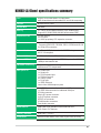
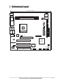
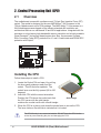
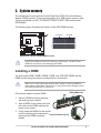
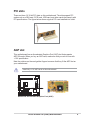
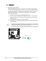
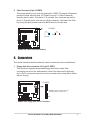
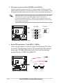
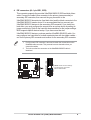
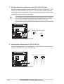
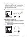
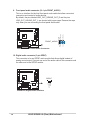
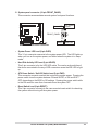
(Dom)
User Guide
Motherboard
K8N8X-LA
Contents
Checklist
K8N8X-LA (Dom) specifications summary ..................................... iii
1.
Motherboard layout ............................................................... 1
2.
Central Processing Unit (CPU) .............................................. 2
Installing the CPU .................................................................. 2
3.
System memory .................................................................... 3
Installing a DIMM ................................................................... 3
4.
Expansion slots ..................................................................... 4
Standard interrupt assignments ............................................ 4
IRQ assignments for this motherboard .................................. 4
PCI slots ................................................................................ 5
AGP slot ................................................................................ 5
5.
Jumpers ................................................................................. 6
6.
Connectors ............................................................................ 8
Product Name:
Manual Revision:
Release Date:
ii
K8N8X-LA (Dom)
E1601
March 2004
K8N8X-LA (Dom) specifications summary
CPU
Socket 754 for AMD Athlon™64 processor
AMD 64 architecture that enables 32- and 64-bit computing
Chipset
NVIDIA nForce 3 250
System Bus
800 MHz
Memory
2 x 184-pin DDR DIMM sockets for up to 2GB memory
Supports PC3200/2700/2100/1600 double-sided DDR
Expansion slots
1 x AGP 8X slot
3 x PCI slots
1 x ASUS proprietary PCI expander connector
IDE
2 x UltraDMA100/66/33 connectors, PIO Mode 3/4
Supports ATAPI IDE, CD-ROM, CD-R, CD-RW and LS-120
2 x Serial ATA connectors
Onboard Audio
RealTek ALC650 6-channel audio CODEC subsystem
AC’97 2.2 compliant
Onboard LAN
CK8S MAC + Realtek RTL8201BL LAN PHY
Onboard IEEE 1394
TI TSB43AB22A supports 2 x IEEE1394 ports with 400/200/
100Mbps data transfer rate
Hardware monitoring
Super I/O integrated monitoring of CPU and system fan
rotations and CPU temperature
Rear panel I/O
1 x Parallel port
1 x Serial port
1 x PS/2 keyboard port
1 x PS/2 mouse port
4 x USB 2.0 ports
1 x RJ-45 port
1 x IEEE 1394 port
Line In/Line Out/Microphone ports
Internal I/O
2 x USB 2.0 connectors for additional 4 USB ports
1 x IEEE 1394 connector for additional 1394 port
CPU fan connector
20-pin ATX power connector
4-pin ATX power connector
S/PDIF out connector
CD/AUX audio connectors
Front Audio connector
BIOS features
4Mb Flash ROM, AMI BIOS with Enhanced ACPI,
DMI, Green, PnP features
Industry Standard
USB 2.0/1.1, PCI 2.2
Form factor
Micro-ATX form factor: 9.6 in x 9.6 in (24.5 cm x 24.5 cm)
iii
iv
1. Motherboard layout
24.5cm (9.64in)
CLPWD
PS/2
T: Mouse
B: Keyboard
Super
I/O
COM1
DDR DIMM2 (64/72 bit, 184-pin module)
4Mb
BIOS
PARALLEL PORT
DDR DIMM1 (64/72 bit, 184-pin module)
ATX12V
Bottom:
Top:
Socket 754
Top:Line In
Center:Line Out
Below:Mic In
CHA_FAN
USB1 RJ-45
USB2
Realtek
RTL8201
CPU_FAN
SATA1
Accelerated Graphics Port (AGP)
SATA0
24.5cm (9.64in)
USB1 1394
USB2
PRIMARY_IDE
ATX Power Connector
Bottom: Top:
SECONDARY_IDE
FLOPPY
BAT1
K8N8X-LA
SPDI/F
PCI 1
nVIDIA
nFORCE3
CD_IN
AUX_IN
PCI 2
ALC650
CLRTC
TI
FRONT_AUDIO
TSB43AB22A
PCI 3
BUZZER1
FRONT_1394
F1
FRONT_PANEL1
FRONT_USB2
ASUS K8N8X-LA (Dom) Motherboard
FRONT_USB1
1
2. Central Processing Unit (CPU)
2.1
Overview
The motherboard comes with a surface mount 754-pin Zero Insertion Force (ZIF)
socket. The socket is designed for the new AMD Athlon™ 64 Processor in the
754-pin lidded ceramic micro PGA package. The AMD Athlon™ 64 processor is a
64-bit desktop processor based on the industry-standard x86 instruction set
architecture that can run x86-based 32 and 64-bit applications. Integrated with the
processor is a low-latency high-bandwidth memory controller and a highly scalable
HyperTransport™ technology-based system bus. Also, the processor includes
Error Correcting Code (ECC) protection for L1 and L2 cache data and DRAM ECC
protection with chipkill.
K8N8X-LA
Gold Arrow
K8N8X-LA Socket 754
Installing the CPU
Follow these steps to install a CPU.
1. Locate the Socket 754 and open it by pulling
the lever gently sideways away from the
socket. Then lift the lever upwards. The
socket lever must be fully opened (90 to 100
degrees).
2. Insert the CPU with the correct orientation.
Position the CPU above the socket such that
the CPU corner with the gold triangle
matches the socket corner with a small triangle.
Gold triangle
3. When the CPU is in place, push down the socket lever to secure the CPU.
The lever clicks on the side tab to indicate that it is locked.
The CPU fits only in one correct orientation. DO NOT force the CPU into the
socket to prevent bending the pins and damaging the CPU!
2
ASUS K8N8X-LA (Dom) Motherboard
3. System memory
The motherboard comes with two Double Data Rate (DDR) Dual Inline Memory
Module (DIMM) sockets. These sockets support up to 2GB system memory using
184-pin unbuffered non-ECC PC3200/PC2700/PC2100/PC1600 double-sided
DDR DIMMs.
The following figure illustrates the location of the DDR DIMM sockets.
104 Pins
80 Pins
K8N8X-LA
K8N8X-LA 184-Pin DDR DIMM Sockets
CAUTION: DIMMs are keyed to fit with only one direction. DO NOT force a
DIMM into a socket to avoid damaging the DIMM.
Installing a DIMM
You may install 64MB, 128MB, 256MB, 512MB, and 1GB DDR DIMMs into the
DIMM sockets using the memory configurations in this section.
Make sure to unplug the power supply before adding or removing DIMMs or
other system components. Failure to do so may cause severe damage to both
the motherboard and the components.
Follow these steps to install a DIMM.
DDR DIMM notch
1. Unlock a DIMM socket by pressing
the retaining clips outward.
2. Align a DIMM on the socket such that
the notch on the DIMM matches the
break on the socket.
3. Firmly insert the DIMM into the socket
until the retaining clips snap back in
Unlocked Retaining Clip
place and the DIMM is properly
seated.
ASUS K8N8X-LA (Dom) Motherboard
3
4. Expansion slots
The motherboard has three PCI slots and one Accelerated Graphics Port (AGP) slot.
To install and configure an expansion card:
1. Install an expansion card following the instructions that came with the chassis.
2. Turn on the system and change the necessary BIOS settings, if any.
3. Assign an IRQ to the card. Refer to the tables below.
4. Install the drivers and/or software applications for the expansion card
according to the card documentation.
Standard interrupt assignments
*
IRQ
Priority
Standard Function
0
1
System Timer
1
2
Keyboard Controller
2
N/A
Programmable Interrupt
3*
11
Communications Port (COM2)
4*
12
Communications Port (COM1)
5*
13
Sound Card (sometimes LPT2)
6
14
Floppy Disk Controller
7*
15
Printer Port (LPT1)
8
3
System CMOS/Real Time Clock
9*
4
ACPI Mode when used
10*
5
IRQ holder for PCI steering
11*
6
IRQ holder for PCI steering
12*
7
PS/2 Compatible Mouse Port
13
8
Numeric Data Processor
14*
9
Primary IDE Channel
15*
10
Secondary IDE Channel
These IRQs are usually available for ISA or PCI devices.
IRQ assignments for this motherboard
PCI slot 1
PCI slot 2
PCI slot 3
AGP slot
Onboard 1394 controller
*Onboard USB controller 1
*Onboard LAN
*Onboard audio
A
INTA#
INTB#
INTC#
INTE#
INTD#
-
B
INTB#
INTC#
INTD#
INTD#
-
C
INTC#
INTD#
INTA#
-
D
INTD#
INTA#
INTB#
-
*The onboard USB, LAN and audio IRQs are assigned by the BIOS.
4
ASUS K8N8X-LA (Dom) Motherboard
PCI slots
There are three (3) 32-bit PCI slots on this motherboard. The slots support PCI
cards such as a LAN card, SCSI card, USB card, and other cards that comply with
PCI specifications. The figure below shows a typical PCI card installed into a slot.
AGP slot
This motherboard has an Accelerated Graphics Port (AGP) slot that supports
AGP 8X cards. When you buy an AGP card, make sure that you ask for one with
+1.5V specification.
Note the notches on the card golden fingers to ensure that they fit the AGP slot on
your motherboard.
Install only +1.5V AGP cards on this motherboard!
AGP Card without Retention Notch
K8N8X-LA
K8N8X-LA Accelerated Graphics Port (AGP)
ASUS K8N8X-LA (Dom) Motherboard
5
5. Jumpers
1. Clear RTC (3-pin CLRTC)
This jumper allows you to clear the Real Time Clock (RTC) RAM in CMOS.
You can clear the CMOS memory of date, time, and system setup parameters
by erasing the CMOS RTC RAM data. The RAM data in CMOS, that include
system setup information, is powered by the onboard button cell battery.
To erase the RTC RAM:
1. Turn OFF the computer and unplug the power cord.
2. Move the jumper cap from pins 2-3 (Default) to pins 1-2 (Clear CMOS).
Keep the cap on pins 1-2 for about 5~10 seconds, then move the cap
back to pins 2-3.
3. Plug the power cord and turn ON the computer.
4. Hold down the <F1> key during the boot process and enter BIOS setup
to re-enter data.
Except when clearing the RTC RAM, never remove the jumper caps on default
position. Removing the cap will cause system boot failure!
K8N8X-LA
CLRTC
1 2
K8N8X-LA Clear RTC RAM
6
Clear CMOS
2 3
Normal
(Default)
ASUS K8N8X-LA (Dom) Motherboard
2. Clear Password (3-pin CLPWD)
This jumper allows you to clear the password in CMOS. To erase the Password
move the jumper cap from pins 2-3 (Default) to pins 1-2 (Clear Password).
Keep the cap on pins 1-2 for about 5~10 seconds, then move the cap back to
pins 2-3. Plug the power cord and turn ON the computer. Hold down the <Del>
key during the boot process and enter BIOS setup to re-enter data.
CLPWD
2 1
3 2
Normal
(Default)
Clear Password
K8N8X-LA
K8N8X-LA Clear Password Setting
6. Connectors
This section describes and illustrates the internal connectors on the motherboard.
1. Floppy disk drive connector (34-1 pin FLOPPY)
This connector supports the provided floppy drive ribbon cable. After
connecting one end to the motherboard, connect the other end to the floppy
drive. (Pin 5 is removed to prevent incorrect insertion when using ribbon cables
with pin 5 plug).
FLOPPY
NOTE: Orient the red markings on
the floppy ribbon cable to PIN 1
K8N8X-LA
PIN 1
K8N8X-LA Floppy Disk Drive Connector
ASUS K8N8X-LA (Dom) Motherboard
7
2. ATX power connectors (20-pin ATXPWR, 4-pin ATX12V)
These connectors connect to an ATX 12V power supply. The plugs from the
power supply are designed to fit these connectors in only one orientation. Find
the proper orientation and push down firmly until the connectors completely fit.
Make sure that your ATX 12V power supply can provide 8A on the +12V lead
and at least 1A on the +5-volt standby lead (+5VSB). The minimum
recommended wattage is 230W, or 300W for a fully configured system. The
system may become unstable and may experience difficulty powering up if the
power supply is inadequate.
ATXPWR
ATX12V
GND +12V DC
+12.0VDC
+5VSB
PWR_OK
COM
+5.0VDC
COM
+5.0VDC
COM
+3.3VDC
+3.3VDC
K8N8X-LA
+5.0VDC
+5.0VDC
-5.0VDC
COM
COM
COM
PS_ON#
COM
-12.0VDC
+3.3VDC
GND +12V DC
K8N8X-LA ATX Power Connector
SATA1
SATA0
GND
RSATA_RXP2
RSATA_RXN2
GND
RSATA_TXN2
RSATA_TXP2
GND
GND
RSATA_RXP1
RSATA_RXN1
GND
RSATA_TXN1
RSATA_TXP1
GND
3. Serial ATA connectors (7-pin SATA1, SATA0, )
These next generation connectors support the thin Serial ATA cables
for primary internal storage devices. The current Serial ATA interface
allows up to 150 MB/s data transfer rate, faster than the standard
parallel ATA with 133 MB/s (UltraDMA133).
K8N8X-LA
K8N8X-LA SATA Connectors
8
ASUS K8N8X-LA (Dom) Motherboard
4. IDE connectors (40-1 pin IDE1, IDE2)
This connector supports the provided UltraDMA100/66/33 IDE hard disk ribbon
cable. Connect the cable’s blue connector to the primary (recommended) or
secondary IDE connector, then connect the gray connector to the
UltraDMA100/66/33 slave device (hard disk drive) and the black connector to the
UltraDMA100/66/33 master device. It is recommended that you connect nonUltraDMA100/66/33 devices to the secondary IDE connector. If you install two
hard disks, you must configure the second drive as a slave device by setting its
jumper accordingly. Refer to the hard disk documentation for the jumper settings.
BIOS supports specific device bootup. If you have more than two
UltraDMA100/66/33 devices, purchase another UltraDMA100/66/33 cable. You
may configure two hard disks to be both master devices with two ribbon cables –
one for the primary IDE connector and another for the secondary IDE connector.
Pin 20 on each IDE connector is removed to match the covered hole on the
UltraDMA cable connector. This prevents incorrect orientation when you
connect the cables.
2.
The hole near the blue connector on the UltraDMA100/66/33 cable is
intentional.
K8N8X-LA
PRIMARY_IDE
SECONDARY_IDE
1.
NOTE: Orient the red markings
(usually zigzag) on the IDE
ribbon cable to PIN 1.
PIN 1
K8N8X-LA IDE Connectors
ASUS K8N8X-LA (Dom) Motherboard
9
5. CPU and System Fan Connectors (3-pin CPU_FAN, CHA_FAN)
The fan connectors support cooling fans of 350mA~740mA (8.88W max.) or a
total of 1A~2.22A (26.64W max.) at +12V. Connect the fan cables to the fan
connectors on the motherboard, making sure that the black wire of each cable
matches the ground pin of the connector.
Do not forget to connect the fan cables to the fan connectors. Lack of sufficient
air flow within the system may damage the motherboard components. These
are not jumpers! DO NOT place jumper caps on the fan connectors!
GND
+12V
Rotation
K8N8X-LA
GND
+12V
Rotation
CHA_FAN CPU_FAN
K8N8X-LA 12-Volt Cooling Fan Power
6. Internal audio connectors (4-pin CD_IN, AUX_IN)
These connectors allow you to receive stereo audio input from sound sources
such as a CD-ROM, TV tuner, or MPEG card.
Ground
K8N8X-LA Internal Audio Connectors
10
ASUS K8N8X-LA (Dom) Motherboard
Left Audio Channel
CD_IN (Black)
Right Audio Channel
Left Audio Channel
K8N8X-LA
Ground
Right Audio Channel
AUX_IN (White)
7. USB headers (10-1 pin FRONT_USB)
If the USB ports on the rear panel are inadequate, a USB header is available
for additional USB ports. The USB header complies with USB 2.0 specification
that supports up to 480 Mbps connection speed. This speed advantage over
the conventional 12 Mbps on USB 1.1 allows faster Internet connection,
interactive gaming, and simultaneous running of high-speed peripherals. You
may connect a USB module to the USB header.
The USB module is purchased separately.
K8N8X-LA USB 2.0 Headers
1
USB+5V
USB_P5USB_P5+
GND
1
USB+5V
USB_P5USB_P5+
GND
K8N8X-LA
USB+5V
USB_P6USB_P6+
GND
NC
FRONT_USB1
USB+5V
USB_P6USB_P6+
GND
NC
FRONT_USB2
8. IEEE 1394 connector (10-1 pin FRONT_1394)
This connector is for a 10-to-6-pin 1394 serial connector cable that connects to
a 1394 module. Attach the 10-1 pin cable plug to this connector, and the 6-pin
cable plug to the 1394 module. You may also connect a 1394-compliant
internal hard disk to this connector.
K8N8X-LA
FRONT_1394
K8N8X-LA IEEE-1394 Connector
1
TPA0+
GND
TPB0+
+12V
TPA0GND
TPB0+12V
GND
NEVER connect a USB cable to any of the IEEE 1394 connectors. Doing so
will damage the motherboard!
ASUS K8N8X-LA (Dom) Motherboard
11
9. Front panel audio connector (10-1 pin FRONT_AUDIO)
This is an interface for the Intel front panel audio cable that allow convenient
connection and control of audio devices.
BLINE_OUT_L
AGND
+5VA
BLINE_OUT_R
By default, the pins labeled LINE_OUT_R/BLINE_OUT_R and the pins
LINE_OUT_L/BLINE_OUT_L are shorted with jumper caps. Remove the caps
only when you are connecting the front panel audio cable.
FRONT_AUDIO
MIC2
MICPWR
Line out_R
NC
Line out_L
K8N8X-LA
K8N8X-LA Front Panel Audio Connector
10. Digital audio connector (3-pin SPDIF)
This connector is for an S/PDIF audio module that allows digital instead of
analog sound output. Connect one end of the audio cable to this connector and
the other end to the S/PDIF module.
SPDI/F
+5V
SPDIFOUT
Ground
K8N8X-LA
K8N8X-LA Digital Audio Interface
12
ASUS K8N8X-LA (Dom) Motherboard
11. System panel connector (10-pin FRONT_PANEL)
This connector accommodates several system front panel functions.
ATX Power
Switch*
PLED+
PLEDPWR
GND
Power LED
HDLED+
HDLEDGround
Reset
FRONT_PANEL
K8N8X-LA
HDLED
Reset SW
K8N8X-LA Front Panel Connector
•
System Power LED Lead (2-pin PLED)
This 3-1 pin connector connects to the system power LED. The LED lights up
when you turn on the system power, and blinks when the system is in sleep
mode.
•
Hard Disk Activity LED Lead (2-pin HDLED)
This 2-pin connector is for the HDD LED cable. The read or write activities of
the device connected to the any of IDE connectors cause the IDE LED to light
up.
•
ATX Power Switch / Soft-Off Switch Lead (2-pin PWR)
This connector connects a switch that controls the system power. Pressing the
power switch turns the system between ON and SLEEP, or ON and SOFT
OFF, depending on the BIOS or OS settings. Pressing the power switch while
in the ON mode for more than 4 seconds turns the system OFF.
•
Reset Switch Lead (2-pin RESET)
This 2-pin connector connects to the case-mounted reset switch for rebooting
the system without turning off the system power.
ASUS K8N8X-LA (Dom) Motherboard
13
14
ASUS K8N8X-LA (Dom) Motherboard