1
DMD50
Universal Satellite Modem
Installation and Operation Manual
TM118
Revision 1.1
Radyne Corporation • 3138 E. Elwood St. • Phoenix, AZ 85034 • (602) 437-9620 • Fax: (602) 437-4811 • www.radn.com
DMD50 Universal Satellite Modem
Warranty Policy
Warranty Policy
WP
Radyne Corp. (Seller) warrants the items manufactured and sold by Radyne Corp. to be free of defects in
material and workmanship for a period of two (2) years from date of shipment Radyne Corp.’s obligation
under its warranty is limited in accordance with the periods of time and all other conditions stated in all
provisions of this warranty.
This warranty applies only to defects in material and workmanship in products manufactured by Radyne
Corp. Radyne Corp. makes no warranty whatsoever concerning products or accessories not of its
manufacture. Repair, or at the option of Radyne Corp., replacement of the Radyne Corp. products or
defective parts therein shall be the sole and exclusive remedy for all valid warranty claims.
Warranty Period
The applicable warranty period shall commence on the date of shipment from a Radyne Corp. facility to the
original purchaser and extend for the stated period following the date of shipment. Upon beginning of the
applicable Radyne Corp. warranty period, all customers’ remedies shall be governed by the terms stated or
referenced in this warranty. In-warranty repaired or replacement products or parts are warranted only for the
remaining unexpired portion of the original warranty period applicable to the repaired or replaced products or
parts. Repair or replacement of products or parts under warranty does not extend the original warranty
period.
Warranty Coverage Limitations
The following are expressly not covered under warranty:
1.
Any loss, damage and/or malfunction relating in any way to shipping, storage, accident, abuse,
alteration, misuse, neglect, failure to use products under normal operating conditions, failure to use
products according to any operating instructions provided by Radyne Corp., lack of routine care
and maintenance as indicated in any operating maintenance instructions, or failure to use or take
any proper precautions under the circumstances.
2.
Products, items, parts, accessories, subassemblies, or components which are expendable in
normal use or are of limited life, such as but not limited to, bulbs, fuses, lamps, glassware, etc.
Radyne Corp. reserves the right to revise the foregoing list of what is covered under this warranty.
Warranty Replacement and Adjustment
Radyne Corp. will not make warranty adjustments for failures of products or parts, which occur after the
specified maximum adjustment period. Unless otherwise agreed, failure shall be deemed to have occurred
no more than seven (7) working days before the first date on which Radyne Corp. receives a notice of
failure. Under no circumstances shall any warranty exceed the period stated above unless expressly agreed
to in writing by Radyne Corp.
Liability Limitations
This warranty is expressly in lieu of and excludes all other express and implied warranties, Including but not
limited to warranties of merchantability and of fitness for particular purpose, use, or applications, and all
other obligations or liabilities on the part of Radyne Corp., unless such other warranties, obligations, or
liabilities are expressly agreed to in writing by Radyne Corp.
All obligations of Radyne Corp. under this warranty shall cease in the event its products or parts thereof
have been subjected to accident, abuse, alteration, misuse or neglect, or which have not been operated and
maintained in accordance with proper operating instructions.
TM118 – Rev. 1.1
iii
Warranty Policy
DMD50 Universal Satellite Modem
In no event shall Radyne Corp. be liable for Incidental, consequential, special or resulting loss or damage of
any kind howsoever caused. Radyne Corp.’s liability for damages shall not exceed the payment, if any,
received by Radyne Corp. for the unit or product or service furnished or to be furnished, as the case may be,
which is the subject of claim or dispute.
Statements made by any person, including representatives of Radyne Corp., which are inconsistent or in
conflict with the terms of this warranty, shall not be binding upon Radyne Corp. unless reduced to writing
and approved by an officer of Radyne Corp.
Warranty Repair Return Procedure
Before a warranty repair can be accomplished, a Repair Authorization must be received. It is at this time
that Radyne Corp. will authorize the product or part to be returned to the Radyne Corp. facility or if field
repair will be accomplished. The Repair Authorization may be requested in writing or by calling:
Radyne Corp.
3138 E. Elwood St.
Phoenix, Arizona 85034 (USA)
ATTN: Customer Support
Phone: (602) 437-9620
Fax: (602) 437-4811
Any product returned to Radyne Corp. for examination must be sent prepaid via the means of transportation
indicated as acceptable to Radyne Corp. Return Authorization Number must be clearly marked on the
shipping label. Returned products or parts should be carefully packaged in the original container, if possible,
and unless otherwise indicated, shipped to the above address.
Non-Warranty Repair
When a product is returned for any reason, Customer and its shipping agency shall be responsible for all
damage resulting from improper packing and handling, and for loss in transit, not withstanding any defect or
nonconformity in the product. By returning a product, the owner grants Radyne Corp. permission to open
and disassemble the product as required for evaluation. In all cases, Radyne Corp. has sole responsibility
for determining the cause and nature of failure, and Radyne Corp.’s determination with regard thereto shall
be final.
iv
TM118 – Rev. 1.1
DMD50 Universal Satellite Modem
Preface
Preface
P
This manual provides installation and operation information for the Radyne DMD50 Universal
Satellite Modem. This is a technical document intended for use by engineers, technicians, and
operators responsible for the operation and maintenance of the DMD50.
Conventions
Whenever the information within this manual instructs the operator to press a pushbutton switch
or keypad key on the Front Panel, the pushbutton or key label will be shown enclosed in "less
than" (<) and "greater than" (>) brackets. For example, the Reset Alarms Pushbutton will be
shown as <RESET ALARMS>, while a command that calls for the entry of a ‘7’ followed by
‘ENTER’ Key will be represented as <7,ENTER>.
Cautions and Warnings
A caution icon indicates a hazardous situation that if not avoided, may result in minor or moderate
injury. Caution may also be used to indicate other unsafe practices or risks of property damage.
A warning icon indicates a potentially hazardous situation that if not avoided, could result in death
or serious injury.
A note icon identifies information for the proper operation of your equipment, including helpful
hints, shortcuts, or important reminders.
TM118 – Rev. 1.1
v
Preface
DMD50 Universal Satellite Modem
Trademarks
Product names mentioned in this manual may be trademarks or registered trademarks of their
respective companies and are hereby acknowledged.
Copyright
©2007, Radyne Corp. This manual is proprietary to Radyne Corp. and is intended for the
exclusive use of Radyne Corp.’s customers. No part of this document may in whole or in part, be
copied, reproduced, distributed, translated or reduced to any electronic or magnetic storage
medium without the express written consent of a duly authorized officer of Radyne Corp.
Disclaimer
This manual has been thoroughly reviewed for accuracy. All statements, technical information,
and recommendations contained herein and in any guides or related documents are believed
reliable, but the accuracy and completeness thereof are not guaranteed or warranted, and they
are not intended to be, nor should they be understood to be, representations or warranties
concerning the products described. Radyne Corp. assumes no responsibility for use of any
circuitry other than the circuitry employed in Radyne Corp. systems and equipment. Furthermore,
since Radyne Corp. is constantly improving its products, reserves the right to make changes in
the specifications of products, or in this manual at any time without notice and without obligation
to notify any person of such changes.
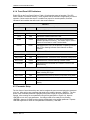
Record of Revisions
Revision
Level
Date
1.0
1.1
1-13-06
5-31-07
Reason for Change
Initial Release
Update to reflect Web Browser Quick Setup Guide, Efficient Drop & Insert,
TCP/IP Internet, HSSI/G.703, HSSI/Ethernet, Updated Clock options,
Updated M&C descriptions, Added Near Side AUPC
Comments or Suggestions Concerning this Manual
Comments or suggestions regarding the content and design of this manual are appreciated. To
submit comments, please contact the Radyne Corp. Customer Service Department.
vi
TM118 – Rev. 1.1
DMD50 Universal Satellite Modem
Table of Contents
Table of Contents
ToC
Section 1 - Introduction ............................................................................................................. 1-1
1.0 Overview ______________________________________________________________ 1-1
1.1 Configurations __________________________________________________________ 1-1
1.1.1 Features/Options Installed at Time of Order __________________________________ 1-2
1.1.2 Feature Upgrades ______________________________________________________ 1-2
1.1.3 Hardware Options ______________________________________________________ 1-2
1.1.4 Radyne Installed Options ________________________________________________ 1-2
1.2 Function Accessibility_____________________________________________________ 1-2
Section 2 - Installation ............................................................................................................... 2-1
2.0 Installation Requirements__________________________________________________ 2-1
2.1 Unpacking _____________________________________________________________ 2-2
2.2 Removal and Assembly ___________________________________________________ 2-2
2.3 Mounting Considerations __________________________________________________ 2-3
2.4 Initial Configuration Check _________________________________________________ 2-3
2.5 Modulator Checkout ______________________________________________________ 2-5
2.5.1 Initial Power-Up________________________________________________________ 2-5
2.5.2 Factory Terminal Setup__________________________________________________ 2-5
2.6 Storage________________________________________________________________ 2-5
Section 3 - Theory of Operation ................................................................................................ 3-1
3.0 Hardware ______________________________________________________________ 3-1
3.0.1 L-Band/IF Printed Circuit Card ____________________________________________ 3-1
3.0.2 Baseband Processing Printed Circuit Card ___________________________________ 3-2
3.0.3 Enhanced Interface Printed Circuit Card_____________________________________ 3-3
3.1 Functional Block Diagram _________________________________________________ 3-3
3.1.1 Front Panel ___________________________________________________________ 3-4
3.1.2 Baseband Processing ___________________________________________________ 3-4
3.1.3 Tx Baseband Processing ________________________________________________ 3-5
3.1.4 Rx Baseband Processing ________________________________________________ 3-5
3.2 Monitor & Control (M&C) Subsystem _________________________________________ 3-5
3.2.1 Terminal Port __________________________________________________________ 3-6
TM118 – Rev. 1.1
vii
Table of Contents
DMD50 Universal Satellite Modem
3.2.2 Modem Remote Communications (RLLP) ____________________________________ 3-6
3.2.3 Ethernet M&C Port _____________________________________________________ 3-6
3.2.4 Modem Monitor Status __________________________________________________ 3-6
3.3 Async Port / ES-ES Communications ________________________________________ 3-7
3.4 Internal Clock ___________________________________________________________ 3-7
3.5 Loopback Features (Terrestrial & IF) _________________________________________ 3-8
3.6 Clocking Options ________________________________________________________ 3-11
3.6.1TX Clock Options ______________________________________________________ 3-11
3.6.1.1 SCTE: Serial Clock Transmit External ____________________________________ 3-12
3.6.1.2 SCT: Serial Clock Transmit ____________________________________________ 3-12
3.6.2 RX Buffer Clock Options _______________________________________________ 3-12
3.6.2.1 RX SAT Clock _______________________________________________________ 3-13
3.6.2.2 SCTE: Serial Clock Transmit External ____________________________________ 3-13
3.6.2.3 SCT: Serial Clock Transmit _____________________________________________ 3-13
3.6.2.4 EXT CLK/EXT BNC: External Clock, J16__________________________________ 3-13
3.6.2.5 EXT IDI: Insert Data In ________________________________________________ 3-13
3.6.3 EXT REF: External Reference, Top BNC Port, J10 ___________________________ 3-14
3.7 RS530/422/V.35 Interfafce (Standard) _______________________________________ 3-14
3.7.1 G.703 Interface (Optional)_______________________________________________ 3-14
3.7.2 HSSI Interface (Optional) _______________________________________________ 3-14
3.7.3 Ethernet Data Interface (Optional) ________________________________________ 3-14
3.8 Reed-Solomon Codec ___________________________________________________ 3-15
3.8.1 Reed-Solomon Operation in the DMD50____________________________________ 3-15
3.8.2 Reed-Solomon Code Rate ______________________________________________ 3-15
3.8.3 Interleaving __________________________________________________________ 3-15
3.9 Asynchronous Overhead Operation (Framing/Multiplexer Capability) _______________ 3-17
3.10 Standard IBS Mode ____________________________________________________ 3-19
3.11 Asynchronous Multiplexer Mode __________________________________________ 3-19
3.12 ESC Backward Alarms__________________________________________________ 3-20
3.12.1 To Disable the ESC Backward Alarms ____________________________________ 3-21
3.13 Satellite Control Channel (SCC)___________________________________________ 3-21
3.13.1 SCC Framing Structure________________________________________________ 3-21
3.13.2 Aggregate Data Rate _________________________________________________ 3-22
3.13.3 Overhead Rate Comparison ____________________________________________ 3-22
3.13.4 Actual Overhead Rate Calculation _______________________________________ 3-23
3.13.5 SCC Overhead Channel Setup __________________________________________ 3-24
3.14 EDMAC Satellite Framing/Deframing Mode__________________________________ 3-25
viii
TM118 – Rev. 1.1
DMD50 Universal Satellite Modem
Table of Contents
3.15 Locating the ID Code Operational Procedure ________________________________ 3-25
3.16 Strap Codes __________________________________________________________ 3-25
Section 4 - User Interfaces ........................................................................................................ 4-1
4.0 User Interfaces__________________________________________________________ 4-1
4.1 Front Panel User Interface _________________________________________________ 4-1
4.1.1 LCD Front Panel Display_________________________________________________ 4-2
4.1.2 Cursor Control Arrow Keys _______________________________________________ 4-2
4.1.3 Numeric Keypad _______________________________________________________ 4-2
4.1.4 Front Panel LED Indicators _______________________________________________ 4-3
4.2 Parameter Setup ________________________________________________________ 4-3
4.3 Front Panel Control Screen Menus __________________________________________ 4-4
4.3.1 Main Menus___________________________________________________________ 4-4
4.3.2 Modulator Menu Options and Parameters ___________________________________ 4-5
4.3.3 Demodulator Menu Options and Parameters ________________________________ 4-11
4.3.4 Interface Menu Options and Parameters ___________________________________ 4-16
4.3.6 Monitor Menu Options and Parameters ____________________________________ 4-21
4.3.7 Alarms Menu Options and Parameters _____________________________________ 4-23
4.3.8 System Menu Options and Parameters ____________________________________ 4-31
4.3.9 Test Menu Options and Parameters _______________________________________ 4-39
4.4 Terminal Mode Control___________________________________________________ 4-41
4.4.1 Modem Terminal Mode Control___________________________________________ 4-41
4.4.2 Modem Setup for Terminal Mode _________________________________________ 4-41
4.5 Terminal Port User Interface ______________________________________________ 4-41
4.6 Connecting the Terminal _________________________________________________ 4-42
4.7 Terminal Screens _______________________________________________________ 4-42
4.8 RS485 Remote Port Interface (RLLP Protocol) ________________________________ 4-42
4.8.1 Protocol Structure _____________________________________________________ 4-43
4.9 Ethernet Remote Port Interface (SNMP & Web Browser) ________________________ 4-43
Section 5 - Rear Panel Interfaces.............................................................................................. 5-1
5.0 Connections ____________________________________________________________ 5-1
5.1 Compact Flash __________________________________________________________ 5-2
5.2 Power Input Modules _____________________________________________________ 5-2
5.2.1 AC Power Input Module _________________________________________________ 5-2
5.2.2 DC Power Input/Switch __________________________________________________ 5-2
5.3 Chassis Connections (Standard)_____________________________________________ 5-2
5.3.1 EXT REF (J10) ________________________________________________________ 5-2
TM118 – Rev. 1.1
ix
Table of Contents
DMD50 Universal Satellite Modem
5.3.2 TX IF (J11) ___________________________________________________________ 5-2
5.3.3 TX L-Band IF (J12) _____________________________________________________ 5-2
5.3.4 RX IF (J13) ___________________________________________________________ 5-2
5.3.5 RX L-Band IF (J14) _____________________________________________________ 5-3
5.3.6 ALARM (J15)__________________________________________________________ 5-3
5.3.7 EXT CLK (J16) ________________________________________________________ 5-3
5.3.8 ASYNC (J17)__________________________________________________________ 5-4
5.3.9 J18 _________________________________________________________________ 5-4
5.3.10 EIA-530 (J19) ________________________________________________________ 5-4
5.3.11 REMOTE (J20) _______________________________________________________ 5-5
5.3.12 ETHERNET (J21) _____________________________________________________ 5-6
5.4 G.703 IDR/IBS Interface (Optional) __________________________________________ 5-6
5.4.1 ESC ALARM (J1) ______________________________________________________ 5-6
5.4.2 64K AUDIO (J2) _______________________________________________________ 5-7
5.4.3 8K DATA (J3) _________________________________________________________ 5-8
5.4.4 G.703 BAL (J4) ________________________________________________________ 5-8
5.4.5 SWITCH INTERFACE (J5) _______________________________________________ 5-9
5.4.6 SD (DDI) (J6) ________________________________________________________ 5-12
5.4.7 DDO (J7) ____________________________________________________________ 5-12
5.4.8 IDI (J8) _____________________________________________________________ 5-12
5.4.9 SD (IDO) (J9) ________________________________________________________ 5-12
5.5 Ethernet Data Interface (Optional) __________________________________________ 5-12
5.6 High-Speed Serial Interface (HSSI) (Optional)_________________________________ 5-13
5.6.1 HSSI (J6)____________________________________________________________ 5-13
5.7 ASI/DVB/M2P Interface (Optional) __________________________________________ 5-14
5.7.1 ASI IN (J1)___________________________________________________________ 5-14
5.7.2 ASI OUT (J2)_________________________________________________________ 5-14
5.7.3 DVB/M2P IN (J3)______________________________________________________ 5-14
5.7.4 DVB/M2P OUT (J4)____________________________________________________ 5-16
5.8 Ethernet Data Interface (Optional) __________________________________________ 5-18
5.9 HSSI / G.703___________________________________________________________ 5-18
5.9.1 64K AUDIO (J2) ______________________________________________________ 5-19
5.9.2 8K DATA (J3) ________________________________________________________ 5-20
5.9.3 G.703 BAL (J4) _______________________________________________________ 5-21
5.9.4 ESC ALARM (J5) _____________________________________________________ 5-22
5.9.5 SD (DDI) (J6) ________________________________________________________ 5-22
5.9.6 DDO (J7) ____________________________________________________________ 5-22
x
TM118 – Rev. 1.1
DMD50 Universal Satellite Modem
Table of Contents
5.9.7 IDI (J8) _____________________________________________________________ 5-23
5.9.8 SD (IDO) (J9) ________________________________________________________ 5-23
5.10 HSSI / Ethernet (J1) ____________________________________________________ 5-23
5.11 Ethernet Data Interface _________________________________________________ 5-24
5.12 GigE Interface _________________________________________________________ 5-24
Section 6 - Maintenance and Troubleshooting........................................................................ 6-1
6.0 Periodic Maintenance_____________________________________________________ 6-1
6.0.1 Clock Adjustment ______________________________________________________ 6-1
6.1 Troubleshooting _________________________________________________________ 6-1
6.1.1 Alarm Faults __________________________________________________________ 6-2
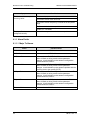
6.1.1.1 Major Tx Alarms ______________________________________________________ 6-2
6.1.1.2 Major Rx Alarms______________________________________________________ 6-3
6.1.1.3 Minor Tx Alarms ______________________________________________________ 6-3
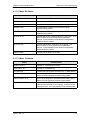
6.1.1.4 Minor Rx Alarms______________________________________________________ 6-4
6.1.1.5 Drop and Insert Alarms ________________________________________________ 6-5
6.1.1.6 Common Major Alarms ________________________________________________ 6-5
6.1.2 Alarm Masks __________________________________________________________ 6-6
6.1.2.1 Active Alarms ________________________________________________________ 6-6
6.1.2.1.1 Major Alarms _______________________________________________________ 6-6
6.1.2.1.2 Minor Alarms _______________________________________________________ 6-6
6.1.2.1.3 Common Equipment Faults____________________________________________ 6-6
6.1.2.2 Latched Alarms ______________________________________________________ 6-6
6.1.2.3 Backward Alarms _____________________________________________________ 6-7
6.2 IBS Fault Conditions and Actions____________________________________________ 6-7
Section 7 - Technical Specifications ........................................................................................ 7-1
7.0 Data Rates _____________________________________________________________ 7-1
7.1 Modulator ______________________________________________________________ 7-1
7.2 Demodulator____________________________________________________________ 7-2
7.3 Plesiochronous Buffer ____________________________________________________ 7-2
7.4 Monitor and Control ______________________________________________________ 7-2
7.5 DMD50 Drop and Insert (Optional)___________________________________________ 7-3
7.6 Terrestrial Interfaces _____________________________________________________ 7-3
7.7 IDR/ESC Interface (Optional) _______________________________________________ 7-3
7.8 IBS/Synchronous Interface (Standard)________________________________________ 7-3
7.9 High-Speed Serial Interface (HSSI) __________________________________________ 7-3
7.10 ASI __________________________________________________________________ 7-3
TM118 – Rev. 1.1
xi
Table of Contents
DMD50 Universal Satellite Modem
7.11 DVB/M2P _____________________________________________________________ 7-3
7.12 Ethernet Data Interface (Optional) __________________________________________ 7-3
7.13 HSSI / G.703 ___________________________________________________________ 7-4
7.14 HSSI /ETHERNET ______________________________________________________ 7-4
7.15 IDR/ESC T3/E3/STS11 Interface (Optional) __________________________________ 7-4
7.16 Environmental _________________________________________________________ 7-4
7.17 Physical ______________________________________________________________ 7-4
7.18 DMD50 Data Rate Limits _________________________________________________ 7-5
7.18.1 Non-DVB ____________________________________________________________ 7-5
7.18.2 DVB________________________________________________________________ 7-6
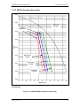
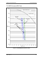
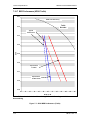
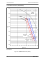
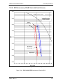
7.19 BER Specifications _____________________________________________________ 7-8
7.19.1 BER Performance (Viterbi) ______________________________________________ 7-8
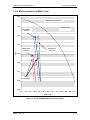
7.19.2 BER Performance (Sequential) ___________________________________________ 7-9
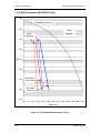
7.19.3 BER Performance (Viterbi with Reed-Solomon) _____________________________ 7-10
7.19.4 BER Performance (Turbo)______________________________________________ 7-11
7.19.5 BER Performance (8PSK Trellis) ________________________________________ 7-13
7.19.6 BER Performance (8PSK Turbo) ________________________________________ 7-15
7.19.7 BER Performance (16QAM Viterbi)_______________________________________ 7-16
7.19.8 BER Performance (16QAM Viterbi with Reed-Solomon) ______________________ 7-17
7.19.9 BER Performance (16QAM Turbo) _______________________________________ 7-18
7.19.10 BER Performance ((O)QPSK Turbo) ____________________________________ 7-19
7.19.11 BER Performance (8PSK Turbo) _______________________________________ 7-19
7.19.12 BER Performance (16QAM Turbo) ______________________________________ 7-19
7.19.13 AGC Output Voltage _________________________________________________ 7-24
Appendix A - Product Options ..................................................................................................A-1
A.0 Hardware Options _______________________________________________________ A-1
A.0.1 G.703/IDR ESC Interface ________________________________________________ A-1
A.0.2 Internal High Stability ___________________________________________________ A-1
A.0.3 DC Input Prime Power __________________________________________________ A-1
A.0.4 ASI/RS-422 Parallel ____________________________________________________ A-1
A.0.5 ASI/LVDS Parallel______________________________________________________ A-1
A.0.6 HSSI ________________________________________________________________ A-1
A.0.7 Ethernet Data Interface__________________________________________________ A-1
A.0.8 HSSI / G.703 _________________________________________________________ A-1
A.0.9 HSSI / ETHERNET ____________________________________________________ A-2
A.0.10 Turbo Product Codec / Variable Reed-Solomon Codec card ____________________ A-2
A.1 Customized Options _____________________________________________________ A-2
xii
TM118 – Rev. 1.1
DMD50 Universal Satellite Modem
Table of Contents
Appendix B - Front Panel Upgrade Procedure ........................................................................B-1
B.0 Introduction ____________________________________________________________ B-1
B.1 Required Equipment _____________________________________________________ B-1
B.2 Upgrade Procedure ______________________________________________________ B-1
B.3 Demonstration Procedure _________________________________________________ B-3
B.3.1 Running in Demonstration Mode __________________________________________ B-5
B.3.2 Canceling Demonstration Mode ___________________________________________ B-6
Appendix C - Carrier Control.....................................................................................................C-1
C.0 States ________________________________________________________________ C-1
C.1 Carrier Off _____________________________________________________________ C-1
C.2 Carrier On _____________________________________________________________ C-1
C.3 Carrier Auto ____________________________________________________________ C-1
C.4 Carrier VSat____________________________________________________________ C-1
C.5 Carrier RTS ____________________________________________________________ C-2
Appendix D - Strap Codes .........................................................................................................D-1
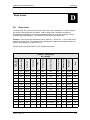
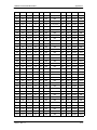
D.1 Strap Codes____________________________________________________________ D-1
D.2 Sample Applications _____________________________________________________ D-4
D.2.1 Operational Case Examples ______________________________________________ D-5
Appendix E - TCP/IP Ethernet Setup ........................................................................................E-1
E.0 Introduction _____________________________________________________________ E-1
E.1 TCP/IP Network Configuration ______________________________________________ E-1
E.2 Network Configuration Summary ____________________________________________ E-3
E.3 Ethernet Test ___________________________________________________________ E-3
E.3.1 Connecting the Modem Ethernet Cable to a Network Link ______________________ E-3
E.3..2 Connecting the Modem Ethernet Cable Directly to a Computer (without a Network) __ E-3
E.3.3 Testing the Ethernet connection using the Ping Program (Optional) _______________ E-6
Appendix F - Web Browser Setup Guide ................................................................................. F-1
F.0 Introduction ____________________________________________________________ F-1
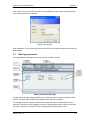
F.1 WEB Users Configuration _________________________________________________ F-1
F.1.1 Change Web User Name ________________________________________________ F-3
F.1.2 Change Authentication Password __________________________________________ F-3
F.1.3 Change Access Rights __________________________________________________ F-3
F.2 Modem Web Site ________________________________________________________ F-4
F.3 Web Page Appearance ___________________________________________________ F-5
TM118 – Rev. 1.1
xiii
Table of Contents
DMD50 Universal Satellite Modem
Appendix G - AUPC Operation ................................................................................................. G-1
G.1 Automatic Uplink Power Control (AUPC Operation) _____________________________ G-1
G.1.1 Radyne AUPC _________________________________________________________ G-1
G.1.2 EF AUPC ____________________________________________________________ G-2
G.1.3 Near Side AUPC _______________________________________________________ G-2
Appendix H - Drop and Insert (D&I) ____________________________________________ H-1
H.0 Drop and Insert (D&I) ____________________________________________________ H-1
H.0.1 Drop Only ____________________________________________________________ H-3
H.0.2 Insert Only ___________________________________________________________ H-3
H.0.3 Mode Selection________________________________________________________ H-5
H.0.3.1 PCM-30 ____________________________________________________________ H-5
H.0.3.2 PCM-30C___________________________________________________________ H-5
H.0.3.3 PCM-31 ____________________________________________________________ H-5
H.0.3.4 PCM-31C___________________________________________________________ H-5
H.0.3.5 T1-D4/T1-D4-S ______________________________________________________ H-6
H.0.3.6 T1-ESF/T1-ESF-S ____________________________________________________ H-6
H.0.4 Multi Destinational Systems ______________________________________________ H-6
H.0.5 Drop and Insert Mapping ________________________________________________ H-7
H.1 Configuring the Modem for Drop and Insert ___________________________________ H-9
H.1.1 Data Rate ____________________________________________________________ H-9
H.1.2 Operational Network Specification ________________________________________ H-10
H.1.3 Terrestrial Framing - Drop Mode/Insert Mode _______________________________ H-10
H.1.3.1 Insert Terrestrial Frame Source_________________________________________ H-11
H.1.4 D&I Sample Configurations and D&I Clock Setup Options______________________ H-11
H.2 D&I Maps and Map Editing _______________________________________________ H-15
Appendix I - Efficient Drop & Insert ........................................................................................... I-1
I.0 Introduction ______________________________________________________________ I-1
I.1 Prerequisite______________________________________________________________ I-1
I.2 Efficient Drop & Insert Mode_________________________________________________ I-2
I.2.1 Calculating the Required Satellite Bandwidth ___________________________________ I-3
I.2.2 Calculating the Basic Efficient D&I Rate _______________________________________ I-3
I.2.3 Calculating the Efficient D&I Rate with E1 Signaling______________________________ I-3
I.2.4 Calculating the Efficient D&I Rate with Enhanced Asynchronous Overhead ___________ I-3
Glossary ...................................................................................................................................... J-1
xiv
TM118 – Rev. 1.1
DMD50 Universal Satellite Modem
TM118 – Rev. 1.1
Table of Contents
xv
DMD50 Universal Satellite Modem
Introduction
Introduction
1
This chapter provides an overview of the DMD50 Universal Satellite Modem. When describing
the equipment, it may be referred to as “the modem”, or “the unit”.
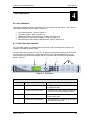
1.0 Overview
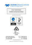
The Radyne Universal Satellite Modem (Figure 1-1) offers the best features of a sophisticated
programmable IBS/IDR and Closed Network Modem, at an affordable price.
Figure 1-1. Universal Satellite Modem Front Panel
This versatile equipment package combines unsurpassed performance with numerous userfriendly Front Panel Programmable Functions. The unit provides selectable functions for different
services: Intelsat IDR and IBS, as well as closed networks. All of the configuration and Monitor
and Control (M&C) Functions are available at the Front Panel. Operating parameters, such as
variable data rates, FEC Code Rate, modulation type, IF Frequencies, IBS/IDR Framing and
interface type can be readily set and changed at the Front Panel by earth station operations
personnel.
The modem operates at all standard IBS and IDR Data Rates up to 8.448 Mbps. Selection of any
data rate is provided over the range of 2.4 Kbps to 52 Mbps in 1 bps steps.
For applications requiring system redundancy, the Modem may be used with the Radyne RCS11
1:1 Redundancy Switch or the RCS20 M:N (N < 9) Redundancy Switch. An Internal Engineering
Service Channel Unit is available to provide voice, data, and alarms for Intelsat IDR applications.
A full range of Industry Standard Interfaces are available. Interface types are selectable from
V.35, RS-232, RS-422/-530, ITU G.703, HSSI, ASI, DVB/M2P and Ethernet Bridge.
1.1 Configurations
The unit can be configured in the following ways:
features and options that are installed when the unit is ordered
feature upgrades
hardware options that are installed to a unit that is sent to a Radyne facility
hardware options that the user can install at their own location
TM118 – Rev. 1.1
1-1
Introduction
DMD50 Universal Satellite Modem
1.1.1 Features/Options Installed at Time of Order
Features installed at the time of ordering are the options pre-installed/initialized in the factory prior
to shipment. These can be reviewed from the front panel. Refer to Section 4, User Interfaces for
information on how to view these features.
Factory installed options are chassis and board configurations that are introduced during
manufacture.
1.1.2 Feature Upgrades
Feature Upgrades are a simple and quick way of changing the feature set of an installed modem.
Feature upgrades are how most options are implemented. Features may be purchased at any
time by contacting a Radyne Corp. salesperson. Refer to Section 4 and Appendix D, for
information on how upgrade features are enabled.
1.1.3 Hardware Options
Hardware options (refer to Appendix A) are purchased parts that can be installed into the unit at
the customer’s site. A screwdriver is normally the only tool required. Please contact the Radyne
Corp. Customer Service Department for information not limited to availability and to shipping
costs.
Only authorized service personnel should handle and install optional
hardware options.
1.1.4 Radyne Installed Options
Units may also be sent to the Radyne Corp. facility for hardware option installation. Please
contact the Radyne Corp. Customer Service Department for information not limited to availability
and to shipping costs.
1.2 Function Accessibility
All functions can be accessed with a terminal or personal computer via a serial link for complete
remote monitoring and control capability.
1-2
TM118 – Rev. 1.1
DMD50 Universal Satellite Modem
TM118 – Rev. 1.1
Introduction
1-3
DMD50 Universal Satellite Modem
Installation
Installation
2
This section provides unpacking and installation instructions, and a description of external
connections and backward alarm information.
2.0 Installation Requirements
The Modem is designed to be installed within any standard 19-inch (48.26 cm) wide equipment
cabinet or rack. It requires one rack unit (RU) of mounting space (1.75 inches/4.45 cm) vertically
and 19.25 inches (48.89 cm) of depth. Including cabling, a minimum of 19.5 inches (49.53 cm) of
rack depth is required. The rear panel of the modem is has power entering from the left and IF
Cabling entering from the right (as viewed from the rear of the unit). Data and Control Cabling
can enter from either side. The modem can be placed on a table or suitable surface if required.
PROPER GROUNDING PROTECTION: During installation and setup, the
user must ensure that the unit is properly grounded. The equipment
shall be connected to the protective earth connection through the end
use protective earth protection.
In addition, the IF input and output coax cable shielding must be properly
terminated to the Chassis/unit ground
There are no user-serviceable parts or configuration settings located
inside the Chassis. There is a potential shock hazard internally at the
power supply module.
DO NOT open the Chassis under any
circumstances.
TM118 – Rev. 1.1
2-1
Installation
DMD50 Universal Satellite Modem
Before initially applying power to the unit, it is a good idea to disconnect
the transmit output from the operating ground station equipment. This is
especially true if the current configuration settings are unknown, where
incorrect settings could disrupt existing communications traffic.
The modem contains a Lithium Battery. DANGER OF EXPLOSION exists
if the battery is incorrectly replaced. Replace only with the same or
equivalent type recommended by the manufacturer. Dispose of used
batteries in accordance with local and national regulations.
2.1 Unpacking
The Universal Satellite Modem was carefully packaged to avoid damage and should arrive
complete with the following items for proper installation:
Modem Unit
Power Cord, with applicable AC Connector
Installation and Operation Manual
2.2 Removal and Assembly
The Modem is shipped fully assembled. It does not require removal of the covers for any
purpose in installation.
Always ensure that power is removed from the before removing or
installing any optional modules. Failure to do so may cause damage to
the equipment.
Carefully unpack the unit and ensure that all of the above items are in the carton. If the available
AC mains power at the installation site requires a different cordset from the one included in the
package, then a suitable and approved cordset (for the country where the equipment is to be
installed) will be required before proceeding with the installation.
2-2
TM118 – Rev. 1.1
DMD50 Universal Satellite Modem
Installation
Should the Power Cable/AC Connector be of the wrong type for the installation, either the cable
or the power connector end should be replaced. The power supply itself is designed for universal
AC application. See specifications for appropriate voltages and currents.
2.3 Mounting Considerations
When mounted in an equipment rack, adequate ventilation must be provided. The ambient
temperature in the rack should preferably be between 10° and 35°C, and held constant for best
equipment operation. The air available to the rack should be clean and relatively dry. The
modems may be stacked one on top of the other to a maximum of 10 consecutive units before
providing one (1) RU of space for airflow. Modems should not be placed immediately above a
high-heat or EMF Generator to ensure the output signal integrity and proper receive operation.
Do not mount the in an unprotected outdoor location where there is direct contact with rain, snow,
wind or sun. The only tools required for rack mounting are four (4) customer supplied rackmounting screws and the appropriate screwdriver. Rack mounting brackets are an integral part of
the front bezel of the unit and are not removable.
2.4 Initial Configuration Check
The modem is shipped from the factory with preset factory defaults. Upon initial power-up, a user
check should be performed to verify the shipped modem configuration. Refer to Section 4, User
Interfaces to locate and verify that the following configuration settings are correct:
The Interface Type (V.35, RS-422, RS-232, G.703, etc.) MUST be selected
from the Front Panel BEFORE the mating connectors are installed. Failure
to do so may cause damage to the Universal Interface Module. Power up
the modem, select the appropriate interface type, and then install the
mating connectors.
Transmit (Tx) and Receive (Rx) Interface types are dependent upon the
customer’s order.
TM118 – Rev. 1.1
2-3
Installation
DMD50 Universal Satellite Modem
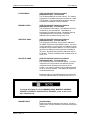
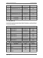
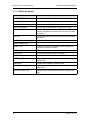
Implementing Strap Code 26 can set the following modem configuration.
Refer to Table 4-4 for an explanation and tabular listing of available Strap
Codes.
The Frequency and Modulator Output Power are set
independently of the strap code.
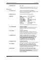
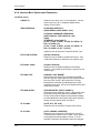
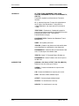
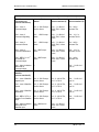
Standard Factory Configuration Settings
Modulator:
Data Rate:
Mode:
Satellite Framing:
Scrambler:
Drop and Insert:
Inner FEC:
Outer FEC:
Modulation:
Frequency:
Modulator Output Power:
2.048 Mbps
Closed Network
None
V.35 (IESS)
Disabled
1/2 Rate Viterbi
Disabled
QPSK
70.000000 MHz
-20 dBm
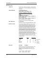
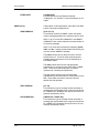
Demodulator:
Data Rate:
Mode:
Satellite Framing:
Scrambler:
Drop and Insert:
Inner FEC:
Outer FEC:
Modulation:
Frequency:
2.048 Mbps
Closed Network
None
V.35 (IESS)
Disabled
1/2 Rate Viterbi
Disabled
QPSK
70.000000 MHz
To lock up the modem, enter ‘IF Loopback Enable’ under the Test Menu, or connect a Loopback
Cable from J11 to J13 on the rear panel of the modem.
Usage of the modems loopback capabilities in conjunction with the
Ethernet data interface can produce undersirable network loops. In order
to run any type of data test with an Ethernet interface you must utilize
two modems connected back to back. Simply using one modem and a
loopback will not produce the desired results.
2-4
TM118 – Rev. 1.1
DMD50 Universal Satellite Modem
Installation
2.5 Modulator Checkout
The following descriptions assume that the modem is installed in a suitable location with prime
AC power and supporting equipment available.
2.5.1 Initial Power-Up
Before initial power up of the modem, it is a good idea to disconnect the
transmit output from the operating ground station equipment. This is
especially true if the current Modulator Configuration Settings are
unknown, where incorrect settings could disrupt the existing
communications traffic. New units from the factory are normally shipped
in a default configuration which includes setting the transmit carrier off.
Turn on the unit by placing the Rear Panel Switch (located above the power entry connector) to
the On Position. Upon initial and subsequent power-ups, the Microprocessor will test itself and
several of its components before beginning its Main Monitor/Control Program. These power-up
diagnostics show no results if successful. If a failure is detected, the Fault LED will illuminate.
The initial field checkout of the modem can be accomplished from the Front Panel or in the
Terminal Mode. The Terminal Mode has the advantage of providing full screen access to all of
the modem’s parameters, but requires a separate terminal or computer running a Terminal
Program. The Terminal Mode is enabled from the front panel in the System M&C Submenus.
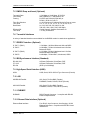
2.5.2 Factory Terminal Setup
The factory terminal setup is as follows:
Emulation Type:
Baud Rate:
Data Bits:
Parity:
Stop Bits:
VT-100 (can be changed)
19.2 K (Can be changed via Front Panel)
8
No Parity (Fixed)
1 Stop Bit
2.6 Storage
It is recommended that the unit be stored in its original sealed packing. The unit should be stored
in a dry location where the temperature is stable, away from direct contact with rain, snow, wind,
sun, or anything that may cause damage.
TM118 – Rev. 1.1
2-5
Installation
2-6
DMD50 Universal Satellite Modem
TM118 – Rev. 1.1
DMD50 Universal Satellite Modem
Theory of Operation
Theory of Operation
3
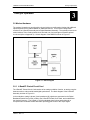
3.0 Modem Hardware
The modem is based on a two printed circuit card (minimum configuration) design with additional
optioned printed circuit cards available for additional features. The minimum configuration
consists of an L-Band/IF Assembly and a Digital Baseband Assembly. The optional printed circuit
cards include a Turbo Codec printed circuit card and one of several types of Interface printed
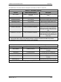
circuit card (refer to Appendix A). A block diagram of the DMD50 is shown in Figure 3.1.
Figure 3-1. Block Diagram
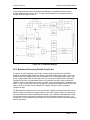
3.0.1 L-Band/IF Printed Circuit Card
The L-Band/IF Printed Circuit Card consists of an analog modulation function, an analog complex
downconversion, and two wide-band digital synthesizers. The block diagram of the L-Band/IF
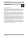
Assembly is shown in Figure 3-2.
In the modulator, analog in-phase (I) and quadrature (Q) signals are generated on the Digital
Baseband Printed Circuit Card, routed to the L-Band/IF Printed Circuit Card, and modulated at
the desired frequency. The L-Band or 70/140 modulated signal is then passed through a
microprocessor controlled variable attenuator providing gain control of the output signal.
TM118 – Rev. 1.1
3-1
Theory of Operation
DMD50 Universal Satellite Modem
In the complex downconverter, the signal for demodulation is amplified and sent through a
variable wideband attenuator for AGC. The gain-controlled signal is then passed through a
complex downconverter to a low IF.
Figure 3-2. IF Card Block Diagram
3.0.2 Baseband Processing Printed Circuit Card
The advent of million-plus gate count FPGAs, advanced logic synthesis tools, and DSPs
providing hundreds of MIPs enabled the design of a software configurable modem. Large, fast
FPGAs now provide designers with what is essentially an on the fly programmable ASIC. High
speed, complex digital logic functions that previously could only be implemented in dedicated
integrated circuits are now downloaded from a micro-controller through a serial or peripheral
interface. When a new digital logic function is needed, a new configuration file is loaded into the
FPGA. There is no limit to the number of digital logic configurations available to the FPGA, aside
from the amount of Flash memory available to the system microprocessor for storage of
configuration files.
The Baseband Processing Printed Circuit Card provides a flexible architecture that allows many
different modes of terrestrial and satellite framing, various FEC options, digital voice processing,
and several different modulation/demodulation formats. Also included on the Baseband Printed
Circuit Card are three synchronous interfaces, an EIA-530 Interface supporting RS-422, V.35,
and RS-232. All three interfaces are provided on the same DB-25 Connector, and are selectable
from the front panel.
3-2
TM118 – Rev. 1.1
DMD50 Universal Satellite Modem
Theory of Operation
The Baseband Printed Circuit Card also contains the Monitor and Control (M&C) Circuitry
responsible for:
Programmable part setup and initialization
Continuous control and adjustment of some functions
Calibration
Monitoring fault status
Calculating and displaying measurements
User monitor and control interface including front panel and remote
Units configuration and feature set
The M&C System is based on a powerful microprocessor with a large amount of Flash memory.
several bus architectures are used to interconnect the M&C to all components of the DMD50.
Communication to the outside world is done via connections to the remote port, terminal port,
Ethernet port, and alarm ports. The M&C runs off of software programmed into its Flash memory.
the memory can be reprogrammed via the Ethernet port to facilitate changes in software.
3.0.3 Enhanced Interface Printed Circuit Card
The normal terrestrial data for the Baseband Processing Card can be re-routed to the enhanced
interface card. The enhanced interface card adds a variety of connections to the modem for
additional applications
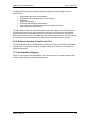
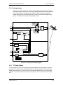
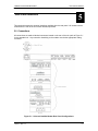
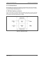
3.1 Functional Block Diagram
Figure 3-3 represents the Functional Blocks. The modem is shown in a typical application with
customer data, Tx/Rx RF equipment and an antenna.
TM118 – Rev. 1.1
3-3
Theory of Operation
DMD50 Universal Satellite Modem
Figure 3-3. Universal Satellite Modem Functional Block Diagram
3.1.1 Front Panel
The Front Panel includes a 2 x 16 backlit LCD Display, Indicator LEDs, and a Numeric Keypad
(refer to Section 4.1).
3.1.2 Baseband Processing
The Baseband Processor performs all of the functions required for an IBS/IDR Framing Unit, a
Reed-Solomon Codec, and an E1/T1 Drop and Insert System. In addition, the Baseband
Processing Section provides for transmit clock selection and rate adaptation as well as a rate
adapter and Plesiochronous/Doppler (PD) Buffer in the receive direction. A multiplexer is also
provided for the SCT Clock Source for Loop Timing Applications. The transmit and receive paths
may be configured independently under processor control.
3-4
TM118 – Rev. 1.1
DMD50 Universal Satellite Modem
Theory of Operation
3.1.3 Tx Baseband Processing
The Tx Data and Clock enters the Baseband Processor, passes through a Rate Adapting FIFO
and enters the Framer/Drop Processor. In IDR, IBS, and D&I Modes, the framer adds the
appropriate framing and ESC as defined in IESS-308 and 309. In D&I Mode, the framer acquires
the terrestrial framing structure, E1 or T1, and synchronizes the Drop Processor. The Drop
Processor extracts the desired time slots from the terrestrial data stream and feeds these
channels back to the framer. The framer then places the ‘dropped’ terrestrial time slots into the
desired satellite channel slots. The data is then sent to the Reed-Solomon Encoder.
When enabled, the Reed-Solomon Encoder, encodes the data into Reed-Solomon Blocks. The
blocks are then interleaved and synchronized to the frame pattern as defined by the selected
specification (IESS-308, IESS-309, DVB, etc.). After Reed-Solomon Encoding, the composite
data and clock are applied to the BB Loopback Circuit.
3.1.4 Rx Baseband Processing
The Receive Processor performs the inverse function of the Tx Processor. Data received from
the satellite passes through the BB Loopback Circuit to the Reed-Solomon Decoder to the
Deframer. The Deframer acquires the IBS/IDR/DVB frame, synchronizes the Reed-Solomon
Decoder and extracts the received data and overhead from the frame structure, placing the data
into the PD Buffer, sending the overhead data to the UIM. The data is extracted from the buffer
and is sent to the UIM. Backward Alarm indications are sent to the M&C Subsystem. In Drop
and Insert Mode, the Insert Processor synchronizes to the incoming terrestrial T1/E1 Data
Stream, extracts satellite channels from the PD Buffer, and then inserts them into the desired
terrestrial time slots in the T1/E1 Data Stream.
3.2 Monitor & Control (M&C) Subsystem
The modems M&C system is connected to most of the circuitry on any board contained in the
modem. These connections provide status on the working condition of the circuitry as well as
providing the data required for the various measurements the modem provides. The M&C
processes this information and generates status indications as well as alarms when necessary.
Detailed status information is available via the modems various user interfaces including the
remote and terminal ports. An external summary fault is available on the RS422 Data interface
The M&C contains a high-performance microprocessor and is responsible for overall command
and control of modem functions. The M&C is constantly monitoring all subsystems of the modem
by performing a periodic poll routine and configures the modem by responding to commands
input to the system. During each poll cycle, the status of each of the subsystems is collected and
reported to each of the external ports. Performance statistics such as Eb/No, buffer fill %, etc.
are compiled. If faults are detected, the M&C will take appropriate actions to minimize the effect
of such faults on the system (refer to the Fault Matrices in Section 6).
The modem supports the following M&C protocols:
TM118 – Rev. 1.1
Terminal Interface (Section 3.2.1)
Remote Port Interface (Section 3.2.2)
Ethernet M&C, Web Browser & SNMP (Section 3.2.3)
Modem Status, Alarms & Contact Closures (Section 3.2.4)
3-5
Theory of Operation
DMD50 Universal Satellite Modem
3.2.1 Terminal Port
This port supports an asynchronous control protocol as described in Section 4. It is configured to
support RS-232 signal levels. This port is intended for use in computer-based remote M&C. All
functions of the modem may be monitored and controlled from this port via a common terminal
connected to the Terminal Port. This function is front panel selectable.
The Terminal Mode Control allows the use of an external terminal or computer to monitor and
control the modem from a full screen interactive presentation operated by the modem itself. No
external software is required other than VT-100 Terminal Emulation Software (e.g. “Procomm”
for a computer when used as a terminal. The Control Port is normally used as an RS–232
Connection to the terminal device. The RS-232 operating parameters can be set using the
modem Front Panel and stored in Non-volatile memory for future use.
Refer to the Remote Protocol Manual (TM117) for the Terminal, Remote
and SNMP screens and protocols.
3.2.2 Modem Remote Communications (RLLP)
The Remote Port located on J20 allows for control and monitoring of parameters and functions
via an RS-232 Serial Interface, or RS-485 for RLLP Protocol. ‘Equipment Remote Mode’ setup
can be entered from the front panel or the Web Browser interface under the “System” menu. This
requires the user to first set the Remote Port Control to “Remote” then set the Multidrop Address
as needed followed by setting the Remote Interface to RS232 or RS485.
Control and status messages are conveyed between the modem and all subsidiary modems and
the host computer using packetized message blocks in accordance with a proprietary
communications specification. This communication is handled by the Radyne Link Level Protocol
(RLLP), which serves as a protocol ‘wrapper’ for the RM&C data. Complete information on
monitor and control software is contained in the following sections.
3.2.3 Ethernet M&C Port
This port is dedicated for Ethernet Communications supporting SNMP, FTP and Web Browser.
The port is configured for 10 Base-T communications protocols. The Ethernet M&C Interface
requires a standard RJ45 Male connector. Refer to Appendix D and F for proper setup of the
TCP-IP interface and Web Browser Setup.
3.2.4 Modem Monitor Status
The modems M&C system is connected to most of the circuitry on any board contained in the
chassis. These connections provide status on the working condition of the circuitry as well as
providing the data required for the various measurements the modem provides. The M&C
processes this information and generates status indications as well as alarms when necessary.
Detailed status information is available via the modems various user interfaces (front panel,
remote and terminal). A summary of this information can be connected to external equipment,
switches or alarms via the open collector and/or form-C fault connections
3-6
TM118 – Rev. 1.1
DMD50 Universal Satellite Modem
Theory of Operation
Form-C Contacts:
The UIM provides three Form-C Relays under processor control that appear at J15.
Mod Fault:
De-energized when any transmit side fault is detected.
Demod Fault:
De-energized when any receive side fault is detected.
Common Fault:
De-energized when any fault that is not explicitly a Tx or
Rx Fault such as an M&C or Power Supply Fault.
Open Collector Faults:
The UIM provides two Open Collector Faults that appear at Pins 18 & 21 on J19.
Mod Fault:
Will sink up to 20 ma (maximum) until a transmit or
common fault is detected. Will not sink current if a fault
is detected.
Demod Fault:
Will sink up to 20 ma (maximum) until a receive or
common fault is detected. Will not sink current if a fault
is detected.
The open collector faults are intended for use in redundancy switch applications in order to
provide quick status indications.
3.3 Async Port / ES-ES Communications
This port is dedicated for ES-ES Communications supported by either RS232 or RS485 signal
levels. The baud rate and protocol can be selected from the Front Panel. The port may be
configured for a number of communications protocols. Overhead data to/from the UIM is routed
to/from the framer/deframer. This port is also used by SCC Framing for the in-band data.
3.4 Internal Clock
The time and date is kept in order to ‘time-tag’ system events. User can change the Internal
Clock via the front panel, Web Browser or Terminal ports.
TM118 – Rev. 1.1
3-7
Theory of Operation
DMD50 Universal Satellite Modem
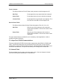
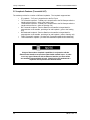
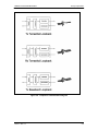
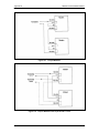
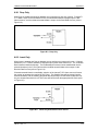
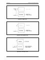
3.5 Loopback Features (Terrestrial & IF)
The modem provides for a number of different loopbacks. The Loopback supported are:
IF Loopback – Tx IF port is looped back to the Rx IF port
TX Terrestrial Loopback - Tx Data port is looped back to the Rx Data port after the
interface driver/receiver. (prior to the framing unit)
TX Baseband Loopback - Tx Data port is looped back to the Rx Data port after the
interface driver/receiver. (after the fraiming unit)
RX Terrestrail Loopback - Receive Data from the satellite is looped back for
retransmission to the satellite, providing a far end loopback. (prior to the framing
unit)
RX Baseband Loopback - Receive Data from the satellite is looped back for
retransmission to the satellite, providing a far end loopback. (after to framing unit)
TX/RX Terrestrial Loopback - provides both Terrestrail loopbacks simultaneously
TX/RX Baseband Loopback - provides both Baseband loopbacks simultaneously
Usage of the modems loopback capabilities in conjunction with the
Ethernet data interface can produce undersirable network loops. In order
to run any type of data test with an Ethernet interface you must utilize
two modems connected back to back. Simply using one modem and a
loopback will not produce the desired results.
3-8
TM118 – Rev. 1.1
DMD50 Universal Satellite Modem
Theory of Operation
Figure 3-4. Loopback Functional Block Diagram
TM118 – Rev. 1.1
3-9
Theory of Operation
DMD50 Universal Satellite Modem
Figure 3-5. Loopback Functional Block Diagram
Figure 3-6. Loopback Functional Block Diagram
3-10
TM118 – Rev. 1.1
DMD50 Universal Satellite Modem
Theory of Operation
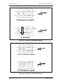
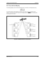
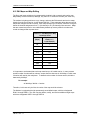
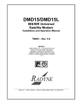
3.6 Clocking Options
The modem supports a number of different clocking options that can be recovered from
the satellite or the terrestrial links. The various clocking options allow users to determine
which clock will best fit their applications. Figure 3-7 gives an overview on how the
modem processes the various clocks for the Tx Clock source and the Rx Buffer Clock
source. Tx and Rx Clocks may be independently locked.
INVERT NONE
INV. TERR&BASE
INV. BASEBAND
INV. TERR DATA
J19
SD
DATA POLARITY
TT
CLOCK &
DATA
SCTE
ST
SCT
High Stability
Oscillator
REF FREQ INTERNAL
SRC
SCR
EXT REF
J10
EXT CLK
J16
MODULATION
CLK POL
NORMAL
INVERTED
HIGH STABILITY
EXTERNAL
Tx CLK
SRC
AUTO
SCT CLK
SRC
TRANSMIT
RECEIVE
J8
IDI
CLOCK
RECOVERY
NORMAL
INVERTED
EXT IDI
EXT BNC
RT
J19
BUFFER CLK POL
BUFFER CLK
SRC
SCT
SCTE
RX SAT
RD
CLOCK & DATA
RECOVERY
DEMODULATION
DATA POLARITY
INVERT NONE
INV. TERR&BASE
INV. BASEBAND
INV. TERR DATA
Figure 3-7. Clocking and Polarity Diagram
3.6.1 TX Clock Options
TX clock options can be recovered from the terrestrial interface, satellite interface or internally
generated. The allows users to select SCTE Clock (Terrestrial) or the SCT internal clock. The
modem also allows user to recover the SCT Clock from the satellite (SCR) or from the modem
internally. The modem allows users to select clock polarity. The Tx clock selections available
are:
TM118 – Rev. 1.1
3-11
Theory of Operation
DMD50 Universal Satellite Modem
The following paragraphs define the types of clocking options available to the user at the Front
Panel.
SCT (Internal Oscillator)
SCTE (External Tx Terrestrial Clock)
Rx Satellite Clock
3.6.1.1 SCTE: Serial Clock Transmit External
The SCTE clock is the Transmit Terrestrial Clock associated with the data interface. SCTE is an
external clock received from the terrestrial equipment and the modem utilizes the terrestrial clock
to lock the internal clock.
In figure 3-9, the Transmit Terrestrial Data enters the modem and is clocked into a dejitter FIFO.
Data is clocked out of the FIFO by the Modulator Clock. The Modulator Clock and Phase-Locked
Loop (PLL), in conjunction with the Dejitter FIFO, which reduces the input jitter. Jitter reduction
exceeds the jitter transfer specified in CCITT G.821.
SCTE is sometimes referred to as Tx Terrestrial Timing or Terminal Timing. Terminal Timing is
reference to the RS422 synchronous interfaces.
3.6.1.2 SCT: Serial Clock Transmit
The SCT clock can be generated internally or recovered from the satellite. The SCT clock source
can be used as the TX clock source, RX Buffer Clock source and the Terrestrial Terminal
equipment for clocking the transmit data. If the SCT clock is recovered from the satellite, then it
is referred to as SCR. SCR is also referred to as Receive Clock, Satellite Clock, or Receive
Timing (RT).
When SCT clock is configured as Internal, the frequency of the clock is set the same as the
Transmit Terrestrial Clock rate. If SCT clock is configured as SCR, the internal clock is set to the
same rate as the incoming receive satellite clock. SCT is sometimes referred to as Internal
Timing or Send Timing (ST). In the event that the satellite clock is lost, the modem will
automatically switch over to the Internal Clock and revert back to SCR when activity is detected.
If SCT is selected, then Terrestrial data that is synchronous to the SCT Clock is required to be
supplied by the modem. It is intended for the terminal equipment to use the SCT as its clock
source. The Autophase Circuit will automatically ensure that the data is clocked correctly into the
modem. Therefore, a return clock is not necessary. The Clock Polarity should be set to Auto.
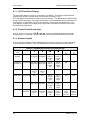
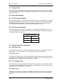
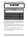
3.6.2 RX Buffer Clock Options
The modem supports a number of RX Buffer clock options that can be recovered from the
satellite, terrestrial links, internally or externally. The various clocking options allow users to
determine which clock will best fit their applications. Figure 3-9 gives an overview on how the
modem processes the various clocks for the Tx Clock and the Rx Buffer Clock. The modem
allows users to select clock polarity Tx and Rx Clocks may be independently locked. The
following RX Buffer clock selections are available:
3-12
Rx Satellite Clock (Recovered from Satellite)
SCTE (External Tx Terrestrial Clock)
SCT (Internal Oscillator)
EXC Clock/EXT BNC (External Clock Source)
EXT IDI (Drop and Insert)
TM118 – Rev. 1.1
DMD50 Universal Satellite Modem
Theory of Operation
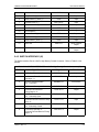
The modem handles RX Buffer clock selections based on source priority levels. The user
assigns priorities to the clock sources based on source selections. Source 1 has the highest
priority and Source 5 being the last resort or lowest priority. If a fallback clock is selected and
activity is lost at the highest priority source, the modem will fall back to the next highest priority
clock with activity. When activity resumes on a higher priority source, the modem resumes using
the higher priority source
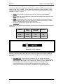
Clock Source
RX SAT
SCTE
SCT
EXC BNC
EXT IDI
1
2
3
4
5
Priority
of
of
of
of
of
5
5
5
5
5
Refer to Front panel setup menus or Web Browser manual TM117.
3.6.2.1 RX SAT Clock
The RX Sat clock is recovered from the satellite that is received from the distant end. If selected
the Buffer Clock is lock to the RX sat clock.
3.6.2.2 SCTE: Serial Clock Transmit External
When SCTE is selected as the Rx Buffer clock, the modem receives the clock from the Transmit
Terrestrial interface.
3.6.2.3 SCT: Serial Clock Transmit
If SCT clock is selected as the RX Buffer clock source, then it should be configured for internal.
SCT is sometimes referred to as Internal Timing or Send Timing (ST).
3.6.2.4 EXT CLK/EXT BNC: External Clock, J16
The External Clock that can be selected as the RX Buffer clock source. This is a 75ohm
unbalanced BNC connector. This clock source is also identified as EXT BNC. The External
Clock is often used as the station master clock. The RX Clock selection can be accessed in the
INTERFACE/RX SETUP menu. The clock frequency, EXT FREQ can be selected, in the
Interface/General Menu.
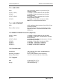
Clock specification:
Frequency:
Level:
1 MHz to 20 MHz
0.5 Vp-p to 5 Vp-p
3.6.2.5 EXT IDI: Insert Data In
External IDI is used only for E1/T1 Drop and Insert applications. The available T1/E1 Frame
Source selections are External, Internal, and IDI/DDO Loopback. The T1/E1 Frame Source
selections can be accessed in the INTERFACE/RX SETUP menus. If Ext IDI is selected as the
RX Buffer clock, then user must first specify T1/E1 Frame Source.
TM118 – Rev. 1.1
External (RX Buffer Clock recovered from the data)
Internal (RX Buffer Clock recoverd from the internal clock)
IDI/DDO Loopback (RX Buffer Clock recoverd from the data and looped back)
3-13
Theory of Operation
DMD50 Universal Satellite Modem
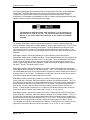
3.6.3 EXT REF: External Reference, Top BNC Port, J10
This is not actually a clock, but does have some clocking implications. When the external
reference is used, the master oscillator within the modem is locked to the external reference, and
the internal accuracy and stability of the unit assumes that of the External Reference. Therefore,
not only are the transmit frequencies locked to the external reference, but the modem’s internal
SCT Oscillator is locked to the external reference as well.
External reference port input is specified at 0 to +6 dBm.
3.7 RS530/422/V.35 Interface (Standard)
Data must be clocked into the modem by either the SCTE or SCT Source. If SCTE is selected as
the Tx Clock Source, then SCTE must be supplied to the modem on the EIA-530 port. The output
of the dejitter buffer will be clocked with this source. SCT should be used if SCTE has excessive
jitter.
3.7.1 G.703 Interface (Optional)
If the G.703 Interface is selected, then the Tx Clock Source will default to SCTE and the Clock
Polarity will default to Auto.
Loop timing with a G.703 Interface or Asymmetrical Data Rates requires external equipment at
the remote end that is capable of using the recovered RD Clock as source timing for (SCTE) SD.
The modem will not manipulate the clock frequency. Therefore, the transmit and receive clock
rates must be equal in order for the modem to perform loop timing.
3.7.2 HSSI Interface (Optional)
If the HSSI Interface is selected, then the Tx Clock Source will default to SCTE and the Clock
Polarity will default to Auto.
3.7.3 Ethernet Data Interface (Optional)
If the Ethernet Data Interface is selected, then the Tx Clock Source will default to SCTE and the
Clock Polarity will default to Normal.
If the Ethernet Data Interface is selected, then the Buffer Clock will default to RxSat and the
Buffer Clock Polarity will default to Normal.
3-14
TM118 – Rev. 1.1
DMD50 Universal Satellite Modem
Theory of Operation
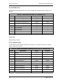
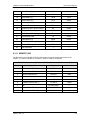
3.8 Reed-Solomon Codec
Refer to Figures 3-16, 3-17, and Table 3-1.
Utilizing a Reed-Solomon (R-S) Outer Codec concatenated with a Convolutional Inner Codec is
an effective way to produce very low error rates even for poor signal-to-noise ratios while
requiring only a small increase in transmission bandwidth. Typically, concatenating an R-S
Codec requires an increase in transmission bandwidth of only 9 – 12% while producing a greater
than 2 dB improvement in Eb/No. R-S is a block Codec where K data bytes are fed into the
encoder which adds 2t = (N – K) check bytes to produce an N byte R-S block. The R-S decoder
can then correct up to “t” erred bytes in the block.
3.8.1 Reed-Solomon Operation
When the Reed-Solomon Codec is enabled, data is fed to the R-S Encoding Section where it is
scrambled, formed into blocks, R-S encoded, and interleaved. Unique words are added so that
the blocks can be reformed in the Receiving Modem (Refer to Figures 3-14 and 3-15). Data is
then sent to the modulator where it is convolutionally encoded, modulated and transmitted to the
satellite.
When the signal is received and demodulated by the Receiving Modem, it is fed to a Viterbi
Decoder for the first layer of error correction. After error correction is performed by the Viterbi
Decoder, the unique words are located and the data is deinterleaved and reformed into blocks.
The R-S Decoder then corrects the leftover errors in each block. The data is then descrambled
and output from the R-S Section.
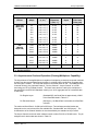
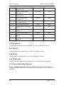
3.8.2 Reed-Solomon Code Rate
The R-S Code Rate is defined by (N, K) where N is the total R-S block size in bytes - data +
check bytes - and K is the number of data bytes input into the R-S Encoder. The transmission
rate expansion required by the R-S Codec is then defined by N/K. The modem automatically sets
the correct R-S code rate for IDR/IBS open network operation in accordance with the data shown
in Table 3-1. The modem allows the following N and K setting: (126, 112), (219, 201), (194, 178),
(225, 205).
Variable Reed-Solomon rates are available on the optional AS/5167 Super Card. Refer to
Appendix A for further information.
3.8.3 Interleaving
Iinterleaving depths of 4, 8, or 12 R-S blocks are allowed. This allows burst errors to be spread
over multiple blocks in order to enhance the error correcting performance of the R-S Codec. For
Intelsat Network Modes, the interleaving depth is automatically set to 4 for QPSK or BPSK, or 8
for 8PSK. In Closed Network Mode, the interleaver depth can be manually set to 4 or 8, and in
DVB Network Mode, the interleaver depth is automatically set to 12.
TM118 – Rev. 1.1
3-15
Theory of Operation
DMD50 Universal Satellite Modem
Figure 3-14. Reed-Solomon Encoder Functional Block Diagram
Figure 3-15. Reed-Solomon Decoder Functional Block Diagram
3-16
TM118 – Rev. 1.1
DMD50 Universal Satellite Modem
Theory of Operation
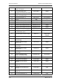
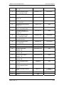
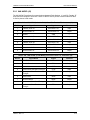
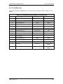
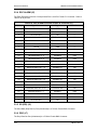
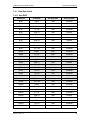
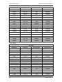
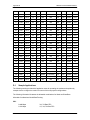
Table 3-1. Reed-Solomon Codes
Type of
Service
Data Rate
(Kbps)
R-S Code
(n, k, t) 1
Bandwidth
Expansion
[ (n/k) -1 ]
Interleaving
Depth
Maximum 2
R-S Codec
Delay (ms)
Small IDR
(With 16/15
O/H)
64
128
256
384
512
768
1024
1536
(126, 112, 7)
(126, 112, 7)
(126, 112, 7)
(126, 112, 7)
(126, 112, 7)
(126, 112, 7)
(126, 112, 7)
(126, 112, 7)
0.125
0.125
0.125
0.125
0.125
0.125
0.125
0.125
4
4
4
4
4
4
4
4
115
58
29
19
15
10
8
5
IDR
(With 96
Kbps O/H)
1544
2048
6312
8448
(225, 205,10)
(219, 201, 9)
(194, 178, 8)
(194, 178, 8)
0.0976
0.0896
0.0899
0.0899
4
4
4
4
9
7
2
<2
8PSK
1544
2048
6312
8448
(219, 201, 9)
(219, 201, 9)
(219, 201, 9)
(219, 201, 9)
0.0896
0.0896
0.0896
0.0896
8
8
8
8
18
13
4
3
DVB
All
(204, 188, 8)
0.0851
12
-
1. n = code length, k = information symbols and t = symbol error correcting capability.
2. Design objective.
3.9 Asynchronous Overhead Operation (Framing/Multiplexer Capability)
The Asynchronous Framing/Multiplexer is capable of multiplexing a relatively low-speed overhead
channel onto the terrestrial data stream resulting in a slightly higher combined or aggregate data
rate through the modem. The overhead channel is recovered at the far end. This added channel
is termed variously “An Overhead Channel”, ”Service Channel”, “Async Channel” or in IESS
terminology an “ES to ES Data Channel.” The basic frame structure used by the multiplexer is
that specified in the IESS-309 Standard, resulting in a 16/15 Aggregate ratio of overhead & data
to data rates.
For Regular Async:
(Standard IBS), the Baud Rate is approximately 1/2000
of the Data Rate listed in Table 3-3.
For Enhanced Async:
(IBS Async.), the Baud Rate is selectable, but Data Rate
is limited.
The maximum Baud Rate is 19,200 bps for IBS Async. Two software-controlled modes are
designed into the card to best utilize the available bits; “Standard IBS” and “IBS (Async)”. The
characteristics of the Channel Interface is also determined by the standard or Async mode.
The Async Channel can be set under software-control to either RS-232 or RS-485 mode. The pin
assignments for both modes are shown in Table 5-3.
TM118 – Rev. 1.1
3-17
Theory of Operation
DMD50 Universal Satellite Modem
The “RS-485” Setting controls the output into tri-state when the modem is not transmitting data,
allowing multiple modem outputs to be connected together.
Table 3-3.
3-18
Kbps
Baud Rate Example for
Standard IBS
Kbps
Baud Rate Example for
Enhanced Mode
128
64
9.6
300
256
128
19.2
600
384
192
32
600
512
256
64
1200
640
320
128
2400
768
384
192
4800
896
448
256
4800
1024
512
320
9600
1152
576
384
9600
1280
640
448
9600
1408
704
512
9600
1536
768
576
9600
1664
832
640
19200
1792
896
704
19200
1920
960
768
19200
1920
960
768
19200
2048
1024
832
19200
896
19200
960
19200
1024
19200
1088
19200
1152
19200
1216
19200
1280
19200
1344
19200
1408
19200
1472
19200
1536
19200
1600
19200
1664
19200
1728
19200
TM118 – Rev. 1.1
DMD50 Universal Satellite Modem
Theory of Operation
1792
19200
1856
19200
1920
19200
1984
19200
2048
19200
3.10 Standard IBS Mode
In the first or “Normal” mode, all bit assignments are per the IBS standard. The bits of Overhead
Housekeeping byte 32 are implemented as shown in Table 3-4 below:
Table 3-4.
Bit 1
ES to ES Data
Channel
This bit is routed directly to the ES to ES Data Channel.
Its data rate is 1/512th of the aggregate rate (or 1/480th of
the through terrestrial data rate), and is normally used to
super-sample an asynchronous data channel.
Bit 2
Frame Alignment
Part of the Frame Alignment word.
Bit 3
Backward Alarm
Transmit and Receive with main processor to activate
Main Alarm/LED.
Bit 4
Multiframe Message
As per IBS.
Bits 5 and 6
Spare
Not currently utilized.
Bits 7 and 8
Encryption Utilization
Not currently utilized.
The ratio of the Through Terrestrial Data Channel Rate to the aggregate rate is 15/16. The
standard transmit and receive channels of the ES to ES Data Channel in Standard IBS Mode are
raw channels operating at the specific bit rate as controlled by the data channel rate, without
buffering. In addition, no clocks are provided with this channel. Since it would be rare that the
data rate provided was exactly that required for a standard rate device, the only method of
communicating using this channel is to allow it to super-sample the user data.
3.11 Asynchronous Multiplexer Mode
Since many of the frame bits in the standard IBS mode are not used, an “Enhanced” Multiplexer
Mode has been implemented that can be engaged under software control. Since this mode
changes the use of many of the framed non-data bits, this mode is only usable when the DMD50
is at both ends of a link.
In this mode, the overhead signaling bytes 16 and 48 can be used to implement a significantly
higher speed ES to ES Data Channel under software control. When implemented, this rate is 16
times that of the normal IBS standard, or 1/30th of the terrestrial data rate (1/32nd of the aggregate
rate).
TM118 – Rev. 1.1
3-19
Theory of Operation
DMD50 Universal Satellite Modem
The IBS Async mode MUST be selected for true Asynchronous channel
operation to be available.
3.12 ESC Backward Alarms
When running in IDR Mode and if the modem has the ESC Option, there will be four Backward
Alarms available for use by the earth stations at each end of the link (both ends must have the
ESC option). These alarms are accessed via the ESC ALARMS Port. The four alarms are
controlled by four relays, each having a normally open, normally closed, and a common
connection. The common connections of these relays (referred to as Backward Alarm Inputs)
can be connected to whichever system on the earth station that the user wishes to trigger the
backward alarm.
When ground is applied to the Common (Input) Connection of one of these relays, that relay and
associated backward alarm will then be in a “no fault” state. When the ground is removed, the
relay and the associated Tx Backward Alarm will toggle to the faulted state. When in the faulted
state, the receive end of the link will receive that backward alarm that is initiated at the transmit
end of the link.
The user can connect whichever systems on the earth stations that they desire to these
Backward Alarms Relays as long as they will supply ground to the Backward Alarm Relay Input in
the “no fault” condition and the ground will be removed in the “faulted” condition.
For example: the user could connect the Demod Summary Fault of the modem to the Backward
Alarm 1 Input, so that if the demod went into Major Alarm (such as a Carrier Loss), Backward
Alarm 1 would be transmitted to the receive end of the link. At the receive end, it would show up
as Rx Backward 1 (Receive Backward Alarm 1).
3-20
TM118 – Rev. 1.1
DMD50 Universal Satellite Modem
Theory of Operation
3.12.1 To Disable the ESC Backward Alarms
If the ESC ALARMS Port will not be used and the Backward Alarm Indications are to be disabled,
you must connect pins 10, 11, 22 and 23 to pin 1 (gnd) on ESC Alarms port.
3.13 Satellite Control Channel (SCC)
The SCC format uses a variable overhead rate to transmit an asynchronous data channel in
addition to the normal data channel. The SCC asynchronous mode implemented on the DMD50
is "PassThru" Mode.
3.13.1 SCC Framing Structure
Each SCC frame consists of the following:
A 10-bit synchronization pattern called the Synchronizing Word.
Multiple variable length slots filled with user data.
Multiple 10-bit control words that contains eight bits of in-band data (the extra two bits
are for the async start/stop).
The number of user data slots and control words per frame is selected by the SCC Control Ratio
Parameter. This can be any value from 1 to 1 through 1 to 7. A higher ratio allows a lower
overhead rate but since there are less Sync Words, there is a higher acquisition time.
The following examples show a control ratio of 1 to 3 and 1 to 1. Example 1 shows three Control
Words for every Synchronizing Word, and Example 2 shows one Control Word for every
Synchronizing Word.
1 to 3 Control Ratio
1 to 1 Control Ratio
TM118 – Rev. 1.1
3-21
Theory of Operation
DMD50 Universal Satellite Modem
The Control Ratio of the receiving units must match the Control Ratio of the transmitting unit.
3.13.2 Aggregate Data Rate
The aggregate data rate equals the following:
User Data Rate + In-Band Rate + Synchronizing Overhead Rate
Because SCC must adjust the overhead so that there are an equal number of user data bits in
each slot, the synchronizing overhead cannot be easily calculated. However, dividing the In-Band
Rate by the Control Ratio can approximate it. The following equation shows the basic calculation
of this rate:
Aggregate Date Rate = User Data Rate + In-Band Rate + (In-Band Rate/Control Ratio)
User Data
Rate
In-Band
Rate
Synchronizing
Overhead
Aggregate Data Rate
As an example, given the following parameters:
User Data Rate:
In-Band Rate:
Control Ratio:
1,024,000 bps
19,200 bps
1 to 7
Aggregate data rate = 1,024,000 + 19,200 + (19,200/7) or approximately 1,045,942
(actually 1045974).
This gives an overhead ratio of 1,045,974/1,024,000 = 1.021
In addition, another constraint changes the actual Aggregate Data Rate. The user data slot size
is limited to 2,500 bits. Because of this, the modem increases the in-band rate to reduce the user
data slot size. This only happens at higher user data rates.
3.13.3 Overhead Rate Comparison
The SCC Overhead Ratio varies depending on the User Data Rate, the In-Band Rate, and the
Control Ratio. This gives SCC the advantage of lower overhead rates when compared to IBS,
which has a fixed overhead ratio of 16/15 or 1.067. Table 3-5 example overhead rates for
different user data and control ratios.
3-22
TM118 – Rev. 1.1
DMD50 Universal Satellite Modem
Theory of Operation
Table 3-5
User Data
Rate
In-Band
Rate
Control
Ratio
Aggregate Data
Rate
Overhead
Ratio
512,000
19,200
1/7
533,974
1.043
1,024,000
19,200
1/7
1,045,974
1.021
2,048,000
19,200
1/7
2,069,951
1.011
3,072,000
19,200
1/7
3,093,943
1.007
4,096,000
19,200
1/7
4,117,951
1.005
6,312,000
19,200
1/7
6,337,248
1.004
6,312,000
19,200
1/3
6,337,606
1.004
6,312,000
19,200
1/1
6,350,418
1.006
3.13.4 Actual Overhead Rate Calculation
The following is the actual calculation the modem does to calculate the overhead ratio:
1.
The modem calculates the minimum in-band rate to limit the size of the user data
slots to 2,500 bits (the result is truncated to an integer).
Minimum In-Band = (User Data Rate * Control Ratio)/((Control Ratio + 1) * 250)
2.
Using the bigger of Minimum In-Band or the selected In-Band, the modem
calculates the number of bits for each user data slot (result is truncated to an
integer).
Slot Bits = (User Data Rate * (Control Ratio * 10))/(In-band Rate * (Control Ratio + 1))
The actual ratio the modem uses is:
Actual Ratio = (Slot Bits + 10)/Slot Bits
Example 1:
User Data Rate:
In-Band Rate:
Control Ratio:
1,024,000 bps
19,200 bps
1 to 7
Minimum In-Band = (1,024,000 * 7)/((7 + 1) * 250) = 3,584 (less than In-Band Rate)
Slot Bits = (1,024,000 * (7 * 10))/(19,200 * (7 + 1)) = 466
Actual Ratio = (466 + 10)/466 = 1.021
Example 2:
User Data Rate:
In-Band Rate:
Control Ratio:
6,312,000 bps
19,200 bps
1 to 7
Minimum In-Band = (6,312,000 * 7)/((7 + 1) * 250) = 22,092 (more than In-Band Rate)
TM118 – Rev. 1.1
3-23
Theory of Operation
DMD50 Universal Satellite Modem
Slot Bits = (6,312,000 * (7 * 10))/(22,092 * (7 + 1)) = 2,500
Actual Ratio = (2,500+ 10)/2,500= 1.004
3.13.5 SCC Overhead Channel Setup
1.
Set the Framing Mode (located under Mod and Demod Data Menus) to SCC.
After doing this, two new menus will appear to the right of the Framing Menu, for
both the Mod and Demod. The new menus will be:
SCC CTL RATIO
SCC INBAND RATE
2.
Set the desired SCC control ratio:
SCC CTL RATIO {1/1, 1/2, 1/3, 1/4, 1/5, 1/6, 1/7}
This allows the user to simulate the framing used by the Satellite Control
Channel Option (Pass-Thru Mode only). The SCC CTL RATIO is the ratio of
overhead in-band data to synchronizing words.
3.
Set the desired SCC in-band rate:
SCC INBAND RATE {300 to 200000}
This allows the user to request the rate of in-band data for the overhead channel.
This sets the overhead amount only. The actual amount of data that can be
passed through the overhead channel will be set under “ES Baud Rate” (see
Step 6 below).
4.
Under the Interface > General menus, locate the TX ASYNC MODE (menu).
5.
Under the TX ASYNC MODE Menu, set the desired ES Interface type:
ES INTERFACE {RS-232, RS-485}
This allows the user to select the interface type.
6.
Under TX ASYNC MODE Menu, set the desired baud rate for the ASYNC Port
(J17). This will be the baud rate that will pass through the overhead channel:
ES BAUD RATE {150 - 19200}
This allows the user to select the baud rate of the ASYNC port (J17) in SCC
Mode.
7.
Under TX ASYNC MODE Menu, set the desired ES BITS/CHAR:
ES BITS/CHAR {7,8}
This allows the user to choose between 7 or 8 bits of data.
3-24
8.
Repeat Steps 4 through 7 under the RX ASYNC MODE (menu)
9.
The physical connection to the overhead channel will be the DB-9 Female Port
labeled ASYNC (J17).
TM118 – Rev. 1.1
DMD50 Universal Satellite Modem
3.14
Theory of Operation
EDMAC Satellite Framing/Deframing Mode
The modem supports EDMAC satellite framing. EDMAC can be enables for both modulator and
demodulator satellite framing when modem is configured in CLOSED NET applications. EDMAC
satellite framing DOES NOT allow control or monitoring of the remote slave modem. On the
demodulator, terrestrial date is framed with NULL EDMAC commands, having no effect at the
remote demodulator. On the demodulator, EDMAC commands are stripped from the satellite data
stream and discarded, leaving the terrestrial data steam intact. EDMAC Framing/Deframing is
provided for compatibility purposes only.
3.15
Locating the ID Code Operational Procedure
The modem has unique ID codes that allow the user to add feature upgrades to the modem
without the unit having to be returned to the factory. Users are required to identify these ID codes
when they want additional features added to their unit. Radyne will supply a new ID code that is
required to be entered in the ID code field. Once the new ID code is entered, the modem will
activate the new features.
Refer to Appendix B for upgrade procedures.
3.16
Strap Codes
The Strap Code is a quick set key that sets many of the modem parameters. For quick setup of
the modem, Strap Codes are very helpful. When a Strap Code is entered, the modem is
automatically configured for the code’s corresponding data rate, overhead, code rate, framing,
scrambler type and modulation. An example of how to set a strap code follows:
Example: In the Ethernet interface <Modulator> Menu, depress the Transmit Gel-tab, then move
the cursor down and depress “General”. Now move the cursor over to ‘Strap Code’. Click inside
the box and enter the new strap code submenu and enter #16. The DMD50 will be automatically
configured to the parameters shown below in the highlighted row ‘Strap Code 16’.
Refer to Appendix H or the various strap code options.
TM118 – Rev. 1.1
3-25
Theory of Operation
3-26
DMD50 Universal Satellite Modem
TM118 – Rev. 1.1
DMD50 Universal Satellite Modem
User Interfaces
User Interfaces
4
4.0 User Interfaces
This section contains information pertaining to the user interfaces for the modem. There are four
user intefaces available for the modem. These are:
•
•
•
•
•
Front Panel Interface – Refer to section 4.1.
Terminal Interface - :Refer to section 4.4.
RS485 Remote Port Interface (RLLP) – Refer to the Section 4.9.
Ethernet Remote Port Interface (SNMP) – Refer to Section 4.10.
Ethernet Remote Port Interface (Web Browser) - Refer to Section 4.10.
4.1 Front Panel User Interface
The Front Panel allows for complete control and monitor of all parameters and functions via a
keypad, LCD display and status LEDs.
The front panel layout is shown in Figure 4-1, showing the location and labeling of the front panel.
The front panel is divided into four functional areas: the LCD Front Panel Display, the Cursor
Control Arrow Keys, the Numeric Keypad, and the Front Panel LED Indicators, each described
below in Table 4-1.
1
2
3
4
Figure 4-1. Front Panel
Table 4-1.
Item Number
Description
Function
1
LCD Front Panel Display
Displays operating parameters and
Configuration data
2
Cursor Control Arrow Keys
Controls the up, down, right and left motion
of the cursor in the LCD Display window
3
Numeric Keypad
Allows entry of numeric data and Clear and
Enter function keys
4
Front Panel LED Indicators
See Paragraph 4.1.4 below for an itemized
description of these LEDs
TM118 – Rev. 1.1
4-1
User Interfaces
DMD50 Universal Satellite Modem
4.1.1 LCD Front Panel Display
The front panel display is a 2 line by 16-character LCD display. The display is lighted and the
brightness can be set to increase when the front panel is currently in use.
The LCD display automatically dims after a period of inactivity. The display has two distinct areas
showing current information. The upper area shows the current parameter being monitored, such
as ‘Frequency’ or ‘Data Rate’. The lower line shows the current value of that parameter. The
LCD display is a single entry window into the large matrix of parameters that can be monitored
and set from the Front Panel.
4.1.2 Cursor Control Arrow Keys
A set of ‘Arrow’ or ‘Cursor’ keys (↑), (↓), (→), (←), is used to navigate the parameter currently
being monitored or controlled. Table 4-2 describes the functions available at the Front Panel.
4.1.3 Numeric Keypad
A 10-Key Numeric Keypad with two additional keys for the ‘Enter’ and ‘Clear’ function allows the
entry of data into the system. Table 4-2 describes the functions available at the Front Panel.
Table 4-2. Edit Mode Key Functions (Front Panel Only)
Parameter
Type
0–9
↑
Fixed Point Changes Digit Toggles ±
Decimal
(If Signed)
↓
←
→
‘Clear’ &
←
‘Clear’ &
→
Toggles ±
(If Signed)
Moves
Cursor 1
Position
Left
Moves
Cursor 1
Position
Right
N/A
N/A
Moves
Cursor 1
Position
Left
Moves
Cursor 1
Position
Right
N/A
N/A
Unsigned Changes Digit Increments Decrements
Hexadecimal
Digit Value Digit Value
Enumerated
N/A
Previous
Value in
List
Next
Value in
List
N/A
N/A
N/A
N/A
N/A
N/A
Moves
Cursor 1
Position
Left
Moves
Cursor 1
Position
Right
N/A
N/A
IP Address Changes Digit Increments Decrements
Digit Value Digit Value
Moves
Cursor 1
Position
Left
Moves
Cursor 1
Position
Right
N/A
N/A
Text Strings
Moves
Cursor 1
Position
Left
Moves
Cursor 1
Position
Right
Clears to
Left of
Cursor
Inclusive
Clears to
Right of
Cursor
Inclusive
Date/ Time Changes Digit
4-2
Changes
Character
Increments Decrements
Character
Character
Value
Value
TM118 – Rev. 1.1
DMD50 Universal Satellite Modem
User Interfaces
4.1.4 Front Panel LED Indicators
Eight LEDs on the Front Panel (Refer to Table 4-3) indicate the status of operation. The LED
colors maintain a consistent meaning. Green signifies that the indication is appropriate for normal
operation, Yellow means that there is a condition not proper for normal operation, and Red
indicates a fault condition that will result in lost communications.
Table 4-3.
LED
Color
Function
Modem LED Indicators
Power
Green
Indicates that the unit is turned on.
Fault
Red
Event
Yellow
Indicates that a condition or event has occurred that the
modem has stored in memory. The events may be viewed
from the Front Panel or in the Terminal Mode.
Remote
Green
Indicates that the unit is in the process of updating firmware
with FTP or flashing indicates some features are demo
enabled.
Indicates a hardware fault for the unit.
Modulator LED Indicators
Transmit On
Green
Indicates that the transmitter is on.
Major Alarm
Red
Minor Alarm
Yellow
Indicates that a Transmit Warning Condition exists.
Test Mode
Yellow
Indicates that the transmitter is involved in a current Test
Mode activity.
Indicates that the Transmit Direction has failed, losing traffic.
Demodulator LED Indicators
Signal Lock
Green
Indicates that the receiver locked to an incoming carrier and
data, including FEC Sync.
Major Alarm
Red
Indicates that the Receive Direction has failed, losing traffic.
Minor Alarm
Yellow
Indicates that a Receive Warning Condition exists.
Test Mode
Yellow
Indicates that the receiver is involved in a current Test Mode
activity.
4.2 Parameter Setup
The four Cursor Control Arrow Keys are used to navigate the menu tree and select the parameter
to be set. After arriving at a parameter that needs to be modified, depress <ENTER>. The first
space of the modifiable parameter highlights (blinks) and is ready for a new parameter to be
entered. After entering the new parameter using the keypad (Refer to Figure 4-2), depress
<ENTER> to lock in the new parameter. If a change needs to be made prior to pressing
<ENTER>, depress <CLEAR> and the display defaults back to the original parameter. Depress
<ENTER> again and re-enter the new parameters followed by <ENTER>.
TM118 – Rev. 1.1
4-3
User Interfaces
DMD50 Universal Satellite Modem
Figure 4-2. Entering New Parameters
Following a valid input, the unit will place the new setting into the nonvolatile EEPROM making it
available immediately and available the next time the unit is powered-up.
4.3 Front Panel Control Screen Menus
The Front Panel Control Screens are broken down into sections under several Main Menus.
4.3.1 Main Menus
MODULATOR
DEMODULATOR
INTERFACE
MONITOR
ALARMS
SYSTEM
TEST
4-4
TM118 – Rev. 1.1
DMD50 Universal Satellite Modem
User Interfaces
4.3.2 Modulator Menu Options and Parameters
NETWORK SPEC
{IDR, IBS, DROP & INSERT, CLOSED NET, DVB SAT}
The Network Spec Command sets a number of
parameters within the modem to meet a specification.
The purpose is to eliminate keystrokes and potential
compatibility problems.
Data rates not covered by a given network specification
will not be allowed. If the mode of operation is selected
after the data rate has been entered, then the data rate
must be compatible with the desired mode of operation
or the network spec will not be allowed. The following
parameters cannot be changed while the unit is in the
given mode of operation:
IDR:
(IESS-308)
For Data rates 1.544, 2.048, 6.312, 8.448 Mbps
Framing Type:
96 Kbps (IDR)
Scrambler Type:
V.35
Spectrum Mask:
Intelsat
For Data Rates < 1.544
Framing Type:
1/15 (IBS)
Scrambler Type:
IESS-309
Spectrum Mask:
Intelsat
IBS:
(IESS-309)
For Data Rates < 2048
Framing Type:
1/15 (IBS)
Scrambler Type:
IESS-309
Spectrum Mask:
Intelsat
Drop & Insert:
Data Rates:
Framing Type:
Scrambler Type:
Spectrum Mask:
n x 64 n = 1, 2, 3, 4, 5, 6, 8,
10,12, 15, 16, 20, 24, 30
1/15 (IBS)
IESS-309
Intelsat
Efficient D&I Closed Network,
Data Rates:
n x 64, N = 1-31 Any combination
Descrambler Type:
IESS-309
Spectrum Mask:
Intelsat
TM118 – Rev. 1.1
4-5
User Interfaces
DMD50 Universal Satellite Modem
DVB: Per EN301-421 & En301-210
Data Rates:
Framing Type:
Scrambler Type:
Spectrum Mask:
All Rates
DVB
DVB
DVB 0.25, 0.35
Closed Net:
All possible combinations allowed, however, DVB
settings requires the DVB network spec. Activates the
AUPC Menu.
STRAP CODE
{Refer to Strap Code Guide, Appendix H}
The Strap Code is a quick set key that sets many
modem parameters. Consult the strap code guide for
available strap codes. Parameters set by strap code:
Data Rate
Inner Code Rate
Satellite Framing
Scrambler
Drop and Insert
Outer Code Rate (Reed-Solomon)
Modulation
Network Spec
IF (menu)
FREQUENCY (MHz)
{50 – 90 MHz, 100 – 180 MHz, or 950 - 2050 MHz}
Allows the user to enter the Modulator IF Output
Frequency of the modem in 1 Hz increments.
4-6
POWER (dBm)
{0 to -25 dBm}
Allows the user to enter the Transmitter Power Level.
CARRIER
{ON, OFF, AUTO, VSAT, RTS}
Allows the user to select the carrier type. Refer to
Appendix E for further information.
SPECTRUM
{NORMAL, INVERTED}
Allows the user to invert the direction of rotation for PSK
Modulation. Normal meets the IESS Specification..
MODULATION
{QPSK, BPSK, OQPSK, 8PSK, 16QAM}
Allows the user to select the modulation type.
SPECTRAL MASK
{Intelsat 0.35, DVB SAT 0.35, DVB SAT 0.25, DVB
SAT 0.20}
Allows the user to set the spectral shape of Tx Data
Filter.
TM118 – Rev. 1.1
DMD50 Universal Satellite Modem
COMPENSATION
User Interfaces
{0.0 – 1.0}
Allows you to offset output power by up to 1 dbm. This
is intended as a correction for user cabinet connectors.
DATA (menu)
DATA RATE (bps)
{Refer to Technical Specs for Data Rates}
Allows the user to set the Data Rate in bps steps via the
Front Panel Arrows or Keypad.
SYMB RATE (sps)
Allows the user to view the Symbol Rate.
INNER FEC
Viterbi
Optional FEC Rates:
Sequential
Trellis 8PSK
Turbo ≤ 20Mbps
Turbo >20Mbps
Comstream Seq
DVB VIT
DVB Trellis
{1/2, 3/4, 7/8, None}
{1/2, 3/4, 7/8}
{2/3}
{.793, .495, 1/2, 3/4, 7/8}
{.750, .875}
{3/4}
{1/2, 2/3, 3/4, 5/6, 7/8}
{2/3, 5/6, 8/9}
Allows the user to select the Rx Code Rate and Type
TPC INTERLEAVER
{DISABLE, ENABLE}
Allows user to disable or enable the TPC Interleaver.
Valid only for Radyne turbo codes TPC.495 and
TPC.793
DIFF CODING
{ENABLED, DISABLE}
Allows the user to enable or disable the Differential
Encoder. Having the encoder enabled ensures proper
phase lock. May not be adjustable in some modes.
SCRAMBLER SEL
{NONE, V.35-IESS, V.35 CITT, V.35 EF, IBS
w/Optional Framing and optional Reed-Solomon,
Reed-Solomon Scrambler w/Optional Framing,
CCITT, V.35FC, OM-73, V.35EF_RS, TPC
SCRAMBLER (Turbo Codec), DVB, EDMAC}
Allows the user to select the descrambler type.
SCRAMBLER CTRL
{ENABLED, DISABLE}
Allows the user to enable or disable scrambler operation.
SAT FRAMING
{1/15 (IBS), 1/15 (Async), 96 Kbps (IDR), DVB,
EDMAC, EFAUPC, SCC, EFFICIENT D&I, None}
Used with IDR, IBS, or Asynchronous Interface Only.
Allows the user to select the framing type.
IN-BAND RATE
{150, 300, 600, 1200, 2400, 4800, 9600, 19200}
Allows the user to select the rate of in-band data for the
ES to ES, Async overhead channel.
Only displayed when Effiecient D&I with Enhanced
Async are selected.
TM118 – Rev. 1.1
4-7
User Interfaces
DMD50 Universal Satellite Modem
SCC CTL RATIO
{1/1, 1/2, 1/3, 1/4, 1/5, 1/6, 1/7},
Allows the user to simulate the framing used by the
Satellite Control Channel Option (Pass Thru Mode only).
The SCC CTL RATIO is the ratio of overhead in-band
data to synchronizing words.
Only displayed when SCC Framing is selected
SCC INBAND RATE
{300 to 200000}, when using SCC Framing
Allows the user to request the rate of in-band data for
the overhead channel.
Only displayed when SCC Framing is selected
TERR FRAMING
{NONE, 188, 204}, when using DVB Network
Specifications
DATA POLARITY
{INV. TERR & BASE, INV. BASEBAND, INV.TERR
DATA, NONE}
Allows the user to invert the Tx Data polarity.
SYMBOL PAIR
{NONE, SWAPPED}
Allows the user to swap the I & Q Channels, when using
BPSK modulation.
ESC OVERHEAD
{VOICE X2, DATA 64KBPS}
IDR ESC Channel used for Voice or 64 K data channel.
Only available when IDR Network is selected.
AUPC (menu)
LOCAL AUPC (menu)
AUPC MODE
The 'LOCAL AUPC CONFIGURATION' Menu contains
the local configuration parameters for the AUPC
Function.
{DISABLED, NEARSIDE, RADYNE, EFDATA}
DISABLED: Allows the user to enable or disable the
Local AUPC Function of the local modem.
EFDATA: Enables EFDATA Local AUPC Function. In
the event that the remote or local demodulator losses
lock, the output power level will adjust itself to the level
settings indicated in the 'REMOTE CL ACTION' Menu or
the 'LOCAL CL ACTION'.
RADYNE: Enables Radyne Local AUPC Function. In
the event the remote demodulator losses lock, the local
output power level will adjust itself to the nominal level.
This nominal power should be set to a level high enough
to re-establish communications regardless of rain fade.
NEARSIDE: Enables NEARSIDE Local AUPC function.
In the event the local demodulator losses lock due to
signal loss, the output power level will adjust itself to the
nominal level. This nominal power should be set to a
level high enough to re-establish communications
regardless of rain fade.
4-8
TM118 – Rev. 1.1
DMD50 Universal Satellite Modem
NOMINAL TX POWER
MINIMUM TX POWER
User Interfaces
{0 TO -25 dB}
This allows the user to set the nominal Transmit Power.
The nominal transmit power is the default output power
level.
{0 to -25 dB}
This allows the user to set the minimum Transmit Power.
EFDATA AUPC: When configured for EFDATA AUPC
the minimum Transmit Power is the lowest power setting
that will be used when the local modem commands a
decrease of the Transmit Power from the Remote
modem.
RADYNE: When configured for Radyne AUPC, the
minimum Transmit Power is the lowest power setting
that will be used when the remote modem commands a
decrease of the Transmit Power from the Local modem.
NEARSIDE: When configured for NEARSIDE AUPC the
minimum Transmit Power is the lowest power setting
that will be used by the local modem when the Eb/No
increases above the Eb/No target.
MAXIMUM TX POWER
{0 to -25 dB}
This allows the user to set the maximum Transmit
Power.
EF AUPC: When configured for EF AUPC, the
maximum Transmit Power is the highest power setting
that the local modem will use when the local modem
commands an increase in Transmit power from the
Remote modem.
RADYNE: When configured for Radyne AUPC, the
maximum Transmit Power is the highest power setting
that will be used when the remote modem commands an
increase of the Transmit Power from the Local modem
NEARSIDE: When configured for NEARSIDE AUPC the
maximum Transmit Power is the highest power setting
that will be used by the local modem when the Eb/No
decreases below the Eb/No target.
TARGET Eb/No
{4.0 to 16 dB}
This allows the user to set the desired Eb/No for the local
receiver.
RADYNE AUPC: When configured for Radyne AUPC,
this setting is compared against the remote Eb/No and
commands to the local modem to increase or decrease
the local transmit power.
EF AUPC: When configured for EF AUPC, this setting
is compared against the local received Eb/No and
commands to the remote modem to increase or
decrease transmit power.
TM118 – Rev. 1.1
4-9
User Interfaces
DMD50 Universal Satellite Modem
NEARSIDE: When configured for NEARSIDE AUPC,
this setting is compared against the received Eb/No of the
local modem and commands to the local modem to
increase or decrease transmit power.
TRACKING RATE
{0.5 to 6.0}
Allows the user to set the rate at which the commands to
increase or decrease Transmit Power are sent. Each
command will result in a 0.5 dB increase or decrease in
Transmit Power from the remote transmitter. The
tracking rate is adjustable from 0.5 dB per minute to 6.0
dB per minute in 0.5 dB steps. (Only available when
EFAUPC is selected as the framing)
LOCAL CL ACTION
{HOLD, NOMINAL, MAXIMUM}
This allows the user to set the Remote Transmit Power
Setting to be used when the local modem receiver loses
lock. The setting can be 'HOLD' (no action taken),
'NOMINAL' (the nominal Transmit Power Setting is
used), and 'MAXIMUM' (the maximum Transmit Power
Setting is used). (Only available when EFAUPC is
selected as the framing)
REMOTE CL ACTION
{HOLD, NOMINAL, MAXIMUM}
This allows the user to set the Local Transmit Power
Setting to be used when the remote modem receiver
loses lock. The setting can be 'HOLD' (no action taken),
'NOMINAL' (the nominal Transmit Power Setting is
used), and 'MAXIMUM' (the maximum Transmit Power
Setting is used).
REMOTE AUPC (menu)
AUPC MODE
LOOPBACK
TX 2047 TEST
4-10
The 'REMOTE AUPC CONFIGURATION' Menu contains
the remote configuration parameters for the AUPC
Function. Remote AUPC menus are only available
when modem is configured for EF AUPC
{DISABLE, EFDATA}
Allows the user to enable or disable the AUPC Function
of the remote modem. The remote AUPC Function is
the response of the local modem to commands for an
increase or decrease of the Transmit Power in 0.5 dB
steps and the command to change to the setting
indicated in the 'REMOTE CL ACTION' Menu of the
remote modem upon receiver loss of lock.
{DISABLE, ENABLE}
Allows the user to enable or disable the Baseband
Loopback Test Mode of the remote modem.
{DISABLE, ENABLE}
Allows the user to enable or disable the Transmit 2047
Pattern Test Mode of the remote modem.
TM118 – Rev. 1.1
DMD50 Universal Satellite Modem
RX 2047 BER:
User Interfaces
Reports the BER measurement of the receiver 2047
Pattern Test Mode of the remote modem. BER is
reported from the 1x10⁻⁵ to 1x10⁻⁷ in tenth decade steps.
if the pattern does not synchronize or is out of range,
‘NO DATA’ will be displayed.
When modems are configured for Radyne AUPC, the remote Eb/No will
be displayed in the Monitor Menus.
REED-SOLOMON (menu)
These selections are visible only when the ReedSolomon Option is installed.
ENABLE/DISABLE
{ENABLED, DISABLE}
Allows the user to Enable/Disable the Reed-Solomon
Encoder.
RS RATE
{Refer to Table 3-1 for standard n/k values}
Displays the currently used n, k Reed-Solomon Codes.
In Closed Net Mode and using the appropriate hardware,
the user may select custom R-S Codes.
INTERLVR DEPTH
{4, 8, 12}
Allows the user to select the Reed-Solomon interleaver
depth. In Closed Net Mode, a depth of 4 or 8 may be
selected.
4.3.3 Demodulator Menu Options and Parameters
NETWORK SPEC
{IDR, IBS, DROP & INSERT, CLOSED NET, DVB SAT}
The Network Spec Command sets a number of
parameters within the modem to meet a specification.
The purpose is to eliminate keystrokes and potential
compatibility problems.
Data rates not covered by a given mode will not be
allowed. If the mode of operation is selected after the
data rate has been entered, then the data rate must be
compatible with the desired mode of operation or the
Network Spec will not be allowed. The following
parameters cannot be changed while the unit is in the
given mode of operation:
IDR:
(IESS-308)
For Data rates 1.544, 2.048, 6.312, 8.448 Mbps
TM118 – Rev. 1.1
4-11
User Interfaces
DMD50 Universal Satellite Modem
Framing Type:
Descrambler type:
Spectrum Mask:
96 Kbps (IDR)
V.35
Intelsat
For Data Rates < 1.544 Mbps
Framing Type:
1/15 (IBS)
Descrambler Type:
IESS-309
Spectrum Mask:
Intelsat
IBS:
(IESS-309)
For Data Rates < 2.048 Mbps
Framing Type:
1/15 (IBS)
Descrambler Type:
IESS-309
Spectrum Mask:
Intelsat
Drop & Insert:
Data Rates:
Framing Type:
Descrambler Type:
Spectrum Mask:
n x 64, n = 1, 2, 3, 4, 5, 6, 8, 10,
12, 15, 16, 20, 24, 30
1/15 (IBS)
IESS-309
Intelsat
Efficient D&I
Data Rates:
Descrambler Type:
Spectrum Mask:
Closed Network,
n x 64, 1-31 Any combination
IESS-309
Intelsat
DVB: Per EN301-421 & En301-210
Data Rates:
All Rates
Framing Type:
DVB
Scrambler Type:
DVB
Spectrum Mask:
DVB 0.25, 0.35
Closed Net:
All possible combinations allowed, however, DVB
settings requires the DVB network spec.
STRAP CODE
{Refer to Strap Code Guide, Appendix H}
The Strap Code is a quick set key that sets many
modem parameters. Consult the strap code guide for
available strap codes. Parameters set by strap code:
Data Rate
Inner Code Rate
Satellite Framing
Scrambler
Drop and Insert
Outer Code Rate (Reed-Solomon)
Modulation
Network Spec
4-12
TM118 – Rev. 1.1
DMD50 Universal Satellite Modem
User Interfaces
IF (menu)
FREQUENCY (MHz)
{50 – 90 MHz, 100 – 180 MHz, or 950 - 2050 MHz}
Allows the user to enter the Modulator IF Frequency in 1
Hz increments.
SPECTRUM
{NORMAL INVERTED}
Allows the user to invert the direction of rotation for PSK
Modulation. Normal meets the IESS Specification.
MODULATION
{QPSK, BPSK, OQPSK, 8PSK, 16QAM}
Allows the user to select the demodulation type.
SPECTRAL MASK
{Intelsat 0.35, DVB 0.35, DVB 0.25, DVB 0.20}
Allows the user to set the spectral shape of Tx Data
Filter.
SWEEP RANGE (kHz)
{±0 to 255 kHz}
Allows the user to set the acquisition range for the
demodulator
SWEEP DELAY (Sec)
{0.0 – 6553.5 sec}
Allows the user to set the reacquisition delay time in
1/10th second increments.
REACQ RANGE (Hz)
{0 – 65535 Hz}
Allows the user to set the reacquisition sweep in 1 Hz
increments.
ADJ CARRIER PWR
{Normal, Supressed}
Allows the user to indicate adjacent carrier as Normal or
Supressed (High Power). Unit will increase or decrease
post decimination gain appropriately.
FAST ACQUISITION
{DISABLED, ENABLED}
Allows the user to disable or enable the Rx fast
acquisition capability.
Limitations of Fast Acquistion:
The maximum symbol rate for Fast Acquistion is 1028Ksps.
Fast Acquistion must be disable for rates greater than 1028Ksps.
Only supports QPSK and 8PSK in a NON-DVB MODE.
Does not support spectral inversion applications.
TM118 – Rev. 1.1
4-13
User Interfaces
INPUT THRESHOLD (dBm)
EB/NO ALARM
DMD50 Universal Satellite Modem
{-30 to 90 dbm}
Allows the user to adjust the low level threshold limit for
input power. Input power level below the threshold limit
will trigger a major alarm on the demodulator.
{0.0 to 9.90 db}
Allows the user to set the desired Eb/No for the local
receiver. This setting is compared against the receive
Eb/No and commands to the remote modem to increase
or decrease Transmit Power accordingly are sent.
DATA (menu)
DATA RATE (bps)
{Refer to Technical Specs for Data Rates}
Allows the user to set the Data Rate in bps steps via the
Front Panel Arrows or Keypad.
SYMB RATE (sps)
Allows the user to view the Symbol Rate.
INNER FEC
Viterbi
Optional FEC Rates:
Sequential
Trellis 8PSK
Turbo ≤ 20Mbps
Turbo >20Mbps
CSC
DVB VIT
DVB Trellis
{1/2, 3/4, 7/8, None}
{1/2, 3/4, 7/8}
{2/3}
{.793, .495, 1/2, 3/4, 7/8}
{.750, .875}
{3/4}
{1/2, 2/3, 3/4, 5/6, 7/8}
{2/3, 5/6, 8/9}
Allows the user to select the Rx Code Rate and Type
4-14
TPC INTERLEAVER
{DISABLED, ENABLED}
Allows the user to disable or enable TPC Interleaver.
Valid only for Radyne turbo codes TPC.495 and
TPC.793.
DIFF CODING
{ENABLED, DISABLE}
Allows the user to enable or disable the Differential
Decoder. Having the decoder enabled ensures proper
phase lock. May not be adjustable in some modes.
SCRAMBLER SEL
{NONE, V.35-IESS, V.35 CITT, V.35 EF, IBS
w/Optional Framing and optional Reed-Solomon,
Reed-Solomon Scrambler w/Optional Framing,
CCITT, V.35FC, OM-73, V.35EF_RS, TPC
SCRAMBLER (Turbo Codec), DVB, EDMAC}
Allows the user to select the descrambler type.
SCRAMBLER CTRL
{ON, OFF}
Allows the user to enable or disable the descrambler
operation.
SAT FRAMING
{1/15 (IBS), 1/15 (Async), 96 Kbps (IDR), EDMAC,
EFAUPC, SCC, EFFICIENT D&I, None}
Used with IDR, IBS, or Asynchronous Interface Only.
Allows the user to select the Framing Type.
TM118 – Rev. 1.1
DMD50 Universal Satellite Modem
User Interfaces
IN-BAND RATE
{150, 300, 600, 1200, 2400, 4800, 9600, 19200}
Allows the user to select the rate of in-band data for the
ES to ES, Async overhead channel. Only displayed
when Effiecient D&I with Esc Enhanced are selected.
SCC CTL RATIO
{1/1, 1/2, 1/3, 1/4, 1/5, 1/6, 1/7}
Allows the user to simulate the framing used by the
Satellite Control Channel Option (Pass Thru Mode only).
The SCC CTL RATIO is the ratio of overhead in-band
data to synchronizing words.
Only displayed when SCC Framing is selected.
SCC INBAND RATE
{300 to 200000},
Allows the user to request the rate of in-band data for
the overhead channel.
Only displayed when SCC Framing is selected.
TERR FRAMING
{NONE, 188, 204}, when using DVB Network Spec
DATA POLARITY
{INV. TERR & BASE, INV. BASEBAND, INV.TERR
DATA, NONE}
Allows the user to invert the Rx Data polarity.
SYMBOL PAIR
{NONE, SWAPPED}
Allows the user to swap the I & Q Channels, when using
BPSK Modulation.
ESC OVERHEAD
{VOICE X2, DATA 64KBPS}
IDR ESC Channel used for Voice or 64 K data channel.
Only available when IDR Network is selected.
REED-SOLOMON (menu)
These selections are visible only when the ReedSolomon Option is installed.
ENABLE/DISABLE
{ENABLED, DISABLED}
Allows the user to Enable/Disable the Reed-Solomon
Encoder.
RS RATE
{Refer to Table 3-1 for standard n/k values}
Displays the currently used n, k Reed-Solomon Codes.
In Closed Net Mode and using the appropriate hardware,
the user may select custom R-S Codes.
INTERLVR DEPTH
{4, 8, 12}
Allows the user to select the Reed-Solomon interleaver
depth.
TM118 – Rev. 1.1
4-15
User Interfaces
DMD50 Universal Satellite Modem
4.3.4 Interface Menu Options and Parameters
TX SETUP (menu)
CIRCUIT ID
Allows the user entry of a Tx Circuit Identifier. Circuits
can be given up to an 11 Character alphanumeric
identity such as LINK1.
TERR INTERFACE
STANDARD INTERFACE
{RS422 SERIAL,RS232 SERIAL, V.35}
OPTIONAL HARDWARE INTERFACES
{M2P PARALLEL, DVB PARALLEL, ASI}
{HSSI}
{ETHERNET 10/100 BASE-T}
{G.703: T1 AMI, T1 B8ZS, , E1 BAL, E1 UNBAL, T2
BAL, T2 UNBAL, E2}
{G.703: T1 AMI, T1 B8ZS, , E1 BAL, E1 UNBAL, T2
BAL, T2 UNBAL, E2, E3, T3, STS1}
Allows the user to select the Transmit Interface Type.
4-16
ETH FLOW CONTROL
{Disabled, Enabled}
Allows the user to disable or enable flow control. Only
visible when Ethernet is selected as the interface type.
ETH DAISY CHAIN
{Disabled, Enabled}
Allows the user to disable the Ethernet Port Daisy
Chaining. Only visible when Ethernet is selected as the
interface type.
ETH QOS TYPE
{NORMAL, PORT BASED}
Selects the priority hierarchy of processing an IEEE
803.3ac Tag, Ipv4 Type of Service Field / Differentiated
Services Field, or Ipv6 Traffic Class Field. The Port
Based priority overrides any standard priority. When
operating in this mode, (JS1) has the highest priority and
(JS4) has the lowest.
ETH QOS QUEUE
{FAIR WEIGHTED, STRICT PRIORITY}
Selects the queue weighting of 8,4,2,1 that insures even
the lowest priority traffic gets some bandwidth. Strict
Priority insures that the higher priority traffic will always
be transmitted before any lower priority traffic. With this
setting, the lower priority traffic can starve.
TX CLK SRC
{SCTE, SCT, EXT CLK}
Allows the user to select the Transmit Clock Source.
TX CLK POL
{AUTO, NORMAL, INVERTED}
Allows the user to select the Clock Polarity for the Tx
Terrestrial Clock relative to the Tx Data. “Auto” detects
wrong polarity and automatically corrects. If G.703
Interface is selected, this selection cannot be changed.
TM118 – Rev. 1.1
DMD50 Universal Satellite Modem
SCT CLK SRC
DROP & INSERT (menu)
User Interfaces
{SCT, SCR}
Allows the user to select SCT Source.SCT is the
internally generated SCT clock. SCR is the Rx Satellite
clock. SCR us used for loop timing.
(Reference Section 3.13, “Drop and Insert Mapping” in
this manual)
DROP MODE
{NONE, T1-D4, T1-ESF, PCM-30, PCM-30C, PCM-31,
PCM-31C, T1-D4-S, T1-ESF-S.}
Drop mode may only be changed from none when the
drop and insert specification is in use.
MAP COPY
{SRC Map
Dest Map}
Allows the user to copy drop and insert maps. Tx Act
map is the drop map currently being used by the
modem. Source and destination may be any of the
following:
TX ACT, RX ACT, TX EDIT, RX EDIT,
USER 1 - USER 8, ROM 1 -ROM 8
SAT CH TERRCH
{1-31
1-31}
The up/down arrow keys allow you to traverse the sat
terr pairings. The slot numbers may be edited using the
keypad.
Allows the user to edit the Tx Edit map and specify the
terrestrial slots that will be dropped into the assigned
satellite channels. The satellite channels are fixed and
the number of channels are determined by the data rate.
The terrestrial time slots available are determined by the
drop mode. When the user has finished editing the Tx
Edit map, it must be copied to the Tx Act map before it
will be used by the modem.
ESC CHAN#1 (dB)
{-20 to +10 dB}
Allows user to select ESC Voice Channel Gain. Only
displayed when IDR NETWORK and VOICE Channel
are selected.
ESC CHAN#2 (dB)
{-20 to +10 dB}
Allows user to select ESC Voice Channel Gain. Only
displayed when IDR NETWORK and VOICE Channel
are selected.
TM118 – Rev. 1.1
4-17
User Interfaces
DMD50 Universal Satellite Modem
RX SETUP (menu)
CIRCUIT ID
Provides entry of Rx Circuit Identifier. Circuits can be
given up to an 11 Character alphanumeric Identity such
as DLINK1
TERR INTERFACE
STANDARD INTERFACE
{RS422 SERIAL,RS232 SERIAL, V.35}
OPTIONAL HARDWARE INTERFACES:
{M2P PARALLEL, DVB PARALLEL, ASI}
{HSSI}
{ETHERNET 10/100 BASE-T}
{G.703: T1 AMI, T1 B8ZS, , E1 BAL, E1 UNBAL, T2
BAL, T2 UNBAL, E2}
{G.703: T1 AMI, T1 B8ZS, , E1 BAL, E1 UNBAL, T2
BAL, T2 UNBAL, E2, E3, T3, STS1}
BUFF SIZE (msec)
BUFFER CLK SRC
Allows the user to select the Transmit Interface
{0 - 64 msecs}
Allows the user to set the Doppler Buffer Size in msec.
The user must assign priorities to the clock sources. 1
being the highest priority and 5 being the last resort.
The menu has three fields; the first field is the name of
the clock source, the second field is the priority entry
area, and the last field is the depth of the list. In the
priority field, the up/down arrow keys will scroll through
the list displaying the names and the current priority.
When the desired clock name is displayed, the number
keys may be used to assign a priority value. Pressing
<Enter> will re-sort the list. Do this until the clock
sources are prioritized in the order desired. Use the
left/right arrow keys to move the cursor to the depth field.
This field assigns the number of entries to use. The
number keypad or the up/down arrows can be used to
change the value.
Clock Source
RX SAT
SCTE
SCT
EXT BNG
EXT IDI
MAP COPY
{SRC Map
Priority
1
2
3
4
5
SRC DEPTH
of
of
of
of
of
3
3
3
3
3
Only these will
be used
Will not be
used since
4>3 and 5>3
Dest Map}
Allows the user to copy drop and insert maps. Tx Act
map is the drop map currently being used by the
modem. Source and destination may be any of the
following:
TX ACT, RX ACT, TX EDIT, RX EDIT,
USER 1 - USER 8, ROM 1 -ROM 8
4-18
TM118 – Rev. 1.1
DMD50 Universal Satellite Modem
SAT CH TERRCH
User Interfaces
{1-31
1-31}
The up/down arrow keys allow you to traverse the sat
terr pairings. The slot numbers may be edited using the
keypad.
Allows the user to edit the Tx Edit map and specify the
terrestrial slots that will be dropped into the assigned
satellite channels. The satellite channels are fixed and
the number of channels are determined by the data rate.
The terrestrial time slots available are determined by the
drop mode. When the user has finished editing the Tx
Edit map, it must be copied to the Tx Act map before it
will be used by the modem.
BUFFER CLOCK POL
{NORMAL, INVERTED}
Allows the user to select the Buffer Clock Polarity for the
Tx Terrestrial Clock relative to the Tx Data. If G.703
Interface is selected, this selection cannot be changed.
DROP & INSERT (menu)
INSERT MODE
{NONE, T1-D4, T1-ESF, PCM-30, PCM-30C, PCM-31,
PCM-31C, T1-D4-S, T1-ESF-S.}
Allows the user to select any of the above.
T1/E1 FRAME SRC
{INTERNAL, EXTERNAL}
Selects the frame source for T1 or E1 framing.
TERR STREAMING
{BYTE OUTPUT, PACKET OUTPUT} ASI only
Byte output = continuous
Packet output = burst
ESC CHAN#1 (dB)
{-20 to +10 dB}
Allows user to select ESC Voice Channel Gain. Only
displayed when IDR NETWORK and VOICE Channel
are selected.
ESC CHAN#2 (dB)
{-20 to +10 dB}
Allows user to select ESC Voice Channel Gain. Only
displayed when IDR NETWORK and VOICE Channel
are selected.
GENERAL (menu)
EXT FREQ (MHz)
TM118 – Rev. 1.1
{Variable Through Data Rate}
Allows the user to select the external clock frequency in
MHz.
4-19
User Interfaces
DMD50 Universal Satellite Modem
REF FREQ SRC
{INTERNAL, EXTERNAL, HIGH STABILITY}
Allows the user to select the Frequency Reference
Source. High Stability is only displayed if the appropriate
hardware is detected.
REF FREQ (MHz)
Allows the user to select the reference clock frequency
in MHz.
TX ASYNC MODE (menu)
TX ASYNC MODE
{ES-ES, ESC ENHANCED}
ES-ES is the normal IBS Async Channel. ESC
Enhanced can be selected in Closed Net and uses the
Overhead Signaling bytes in the IBS Overhead to pass
asynchronous data.
ES INTERFACE
{RS-232, RS-485}
Allows the user to select the interface type.
ES BAUD RATE
{150 - 19200}
Allows the user to select the baud rate in Enhanced
Async Mode. Available rates are listed in Table 3-3.
ES BITS/CHAR
{7,8}
Allows the user to choose between 7 or 8 bit data.
RX ES ENHANCED (menu)
4-20
RX ASYNC MODE
{ES-ES, ESC ENHANCED}
ES-ES is the normal IBS Async Channel. ESC
Enhanced can be selected in Closed Net and uses the
Overhead Signaling bytes in the IBS Overhead to pass
asynchronous data.
ES INTERFACE
{RS-232, RS-485}
Allows the user to select the interface type.
ES BAUDRATE
{150 – 19200}
Allows the user to select the Baud rate in Enhanced
Async Mode.
ES BITS/CHAR
{7,8}
Allows the user to choose between 7 or 8 bit data.
TM118 – Rev. 1.1
DMD50 Universal Satellite Modem
User Interfaces
4.3.6 Monitor Menu Options and Parameters
EVENTS
Displays a history of events recorded in the event buffer.
A maximum of 100 events may be stored in the buffer.
Upon receipt of the 101st event, the first received event
is automatically deleted, and so on, maintaining the
maximum 100 events.
ERASE EVENTS.. PRESS CLEAR
Allows the user to clear the contents of the Event Buffer
by pressing <CLEAR> on the keypad.
INPUT LVL (dBm)
Displays the estimated receive signal level as seen by
the Demodulator.
EBNO (dB)
Displays the estimated Eb/No as seen by the
demodulator.
REMOTE EB/NO
Remote EB/NO displayed when modem is configured for
Radyne AUPC.
RAW BER
Displays the estimated channel error rate (before
decoding) measured by the modem.
CORRECTED BER
The CBER display shows an estimated corrected bit
error rate of the modem. Depending on the symbol rate
the modem is running, the high-end performance scale
of this display will vary (10 E-9, 10-10 or 10-11). At some
symbol rates, a better than scale reading will appear as
0.0 x 10-00. At other symbol rates, it will appear as E**. In
either case, they both mean performance is better than
the scale upper limit.
BIT ERRORS
Displays the current error count from the Viterbi
Decoder.
FREQ OFFSET
Displays the received carrier frequency offset as
measured by the modem.
TOTAL PACKETS
Displays the total number of Ethernet packets received
from the satellite (Only visible when Ethernet is
selected as the interface type).
ERROR PACKETS
Displays the number of error Ethernet packets received
from the satellite (Only visible when Ethernet is
selected as the interface type).
PKT ERROR RATE
Displays the satellite Packet Error Rate (Only visible
when Ethernet is selected as the interface type).
PKT STATS RESET
Allows the user to reset the Ethernet packet statistics by
pressing <Enter> (Only visible when Ethernet is
selected as the interface type).
LINK STATUS (menu)
(the following sub-menus only display when
Ethernet is selected as the interface type)
TM118 – Rev. 1.1
4-21
User Interfaces
DMD50 Universal Satellite Modem
The status of the following ports may be one of the following:
Down:
Unresolved:
10 Mbps Half:
10 Mbps Full:
100 Mbps Half:
100 Mbps Full:
Unused:
The link is down.
Unable to agree on connection speed.
Connected at 10 Base-T Half Duplex.
Connected at 10 Base-T Full Duplex.
Connected at 100 Base-T Half Duplex.
Connected at 100 Base-T Full Duplex.
The port is not available.
JS1 STATUS
{See the note above}
Displays the current status of the LAN Port.
JS2 STATUS
{See the note above}
Displays the current status of the LAN Port.
JS3 STATUS
{See the note above}
Displays the current status of the LAN Port.
JS4 STATUS
{See the note above}
Displays the current status of the LAN Port.
WAN STATUS
{See the note above}
Displays the current status of the WAN Port.
VOLTAGES (menu)
4-22
+1.5V RX SUPPLY
Displays the measured voltage of the 1.5 Volt Rx power
bus located inside the modem.
+1.5V TX SUPPLY
Displays the measured voltage of the 1.5 Volt Tx power
bus located inside the modem.
+3.3V SUPPLY
Displays the measured voltage of the +3.3 Volt power
bus located inside the modem.
+5V SUPPLY
Displays the measured voltage of the +5 Volt power bus
located inside the modem.
+12V SUPPLY
Displays the measured voltage of the +12 Volt power
bus located inside the modem.
+20V SUPPLY
Displays the measured voltage of the +20 Volt power
bus located inside the modem.
TM118 – Rev. 1.1
DMD50 Universal Satellite Modem
-12V SUPPLY
User Interfaces
Displays the measured voltage of the -12 Volt power bus
located inside the modem.
RX BUFFER LEVEL
{0 – 100%}
Displays the status of the Doppler Buffer.
RX BUFFER RESET ((ENTER))
Allows the user to re-center the Doppler Buffer when
<ENTER> is pressed on the keypad.
4.3.7 Alarms Menu Options and Parameters
Masking alarms may cause undesirable modem performance.
CURRENT ALARMS (menu)
TX MAJOR (menu)
Status
Edit Table
FPGA CFG
{Pass/Fail, Unmasked/Masked}
Indicates a transmit FPGA configuration failure.
DSP CFG
{Pass/Fail, Unmasked/Masked}
Indicates a transmit DSP configuration failure.
SCT CLOCK PLL
{Pass/Fail, Unmasked/Masked}
Indicates that the Tx SCT Clock PLL is not locked. This
alarm will flash on during certain modem parameter
changes. A solid indication points toward a configuration
failure within the modem.
{Pass/Fail, Unmasked/Masked}
Indicates that the Tx Symbol Clock PLL is not locked.
This alarm will flash on during certain modem parameter
changes. A solid indication points toward a problem with
the incoming clock to the modem (SCTE).
SYM CLOCK PLL
LB SYNTH PLL
{Pass/Fail, Unmasked/Masked}
Indicates that the Tx L-Band Synthesizer is not locked.
This alarm will flash on during certain modem parameter
changes. A solid indication points toward a configuration
problem within the modem.
IF SYNTH PLL
{Pass/Fail, Unmasked/Masked}
Indicates that the Tx IF Synthesizer is not locked. This
alarm will flash on during certain modem parameter
changes. A solid indication points toward a configuration
problem within the modem.
ETHERNET WAN
{Pass/Fail, Unmasked/Masked}
TM118 – Rev. 1.1
4-23
User Interfaces
DMD50 Universal Satellite Modem
FORCED ALARM
Indicates that the interface card is faulted and will not
pass data (displays only when the Ethernet Card is
installed and the Ethernet Interface is selected).
{DISABLED, ENABLED}
Allows user to disable or enable forcing of a Tx
Summary Alarm.
TX MINOR (menu)
TERR CLK ACT
{Pass/Fail, Unmasked/Masked}
Indicates no Terrestrial Clock activity.
TERR DATA ACT
{Pass/Fail, Unmasked/Masked}
Indicates no Tx Data activity.
TX TERR AIS
{Pass/Fail, Unmasked/Masked}
Indicates that AIS has been detected in the Tx Data
Stream.
DnI FRAME LOCK
{Pass/Fail, Unmasked/Masked}
Indicates the framing unit is unable to find the expected
terrestrial framing pattern.
DnI M-FRAME LOCK
{Pass/Fail, Unmasked/Masked}
Indicates the framing unit is unable to find the expected
inter-frame pattern.
TX DVB FRM LOCK
{Pass/Fail, Unmasked/Masked}
Indicates that Tx input data stream framing does not
match the user selected TX TERR FRAMING.
RX MAJOR (menu)
FPGA CFG
DSP CFG
4-24
{Pass/Fail, Unmasked/Masked}
Indicates a receive FPGA hardware failure.
{Pass/Fail, Unmasked/Masked}
Indicates a receive DSP failure.
SIGNAL LOCK
{Pass/Fail, Unmasked/Masked}
Indicates that the demod is unable to lock to a signal.
INPUT LVL THRESH
{Pass/Fail, Unmasked/Masked}
Indicates Rx signal level has fallen below input
threshold.
FRAME LOCK
{Pass/Fail, Unmasked/Masked}
Indicates that the Framing Unit is unable to find the
expected framing pattern.
MULTIFRAME LOCK
{Pass/Fail, Unmasked/Masked}
This alarm will flash on during certain modem parameter
changes. A solid indication points toward a problem with
the incoming clock to the modem (SCTE).
TM118 – Rev. 1.1
DMD50 Universal Satellite Modem
User Interfaces
LB SYNTH PLL
{Pass/Fail, Unmasked/Masked}
Indicates that the Rx L-Band Synthesizer is not locked.
This alarm will flash on during certain modem parameter
changes. A solid indication points toward a configuration
problem within the modem.
IF SYNTH PLL
{Pass/Fail, Unmasked/Masked}
Indicates that the Rx IF Synthesizer is not locked. This
alarm will flash on during certain modem parameter
changes. A solid indication points toward a configuration
problem within the modem.
ETHERNET WAN
Indicates that the interface card is faulted and will not
pass data (displays only when the Ethernet Card is
installed and the Ethernet Interface is selected).
FORCED ALARM
{DISABLED, ENABLED}
Allows user to enable a forced Rx summary alarm.
RX MINOR (menu)
BUFF UNDERFLOW
{Pass/Fail, Unmasked/Masked}
Indicates that a Doppler Buffer underflow has occurred.
BUFF NEAR EMPTY
{Pass/Fail, Unmasked/Masked}
Indicates that the Doppler Buffer is about to underflow.
BUFF NEAR FULL
{Pass/Fail, Unmasked/Masked}
Indicates that the Doppler Buffer is about to overflow.
BUFF OVERFLOW
{Pass/Fail, Unmasked/Masked}
Indicates that a Doppler Buffer overflow has occurred.
RX DATA ACTIVITY
{Pass/Fail, Unmasked/Masked}
Indicates that there is no Rx Data activity.
{Pass/Fail, Unmasked/Masked}
Indicates that AIS has been detected in the receive
satellite data stream.
SAT AIS
DnI FRAME LOCK
{Pass/Fail, Unmasked/Masked}
Indicates if drop/insert data is frame locked.
DnI M-FRAME LOCK
{Pass/Fail, Unmasked/Masked}
Indicates if drop/insert data has multiframe lock.
INSERT CRC
{Pass/Fail, Unmasked/Masked}
Indicates if the Circular Redundancy Check is passing in
PCM-30C and PCM-31C Modes.
T1/E1 SIGNALING
{Pass/Fail, Unmasked/Masked}
The interface is not deleting the expected signaling
information.
IFEC LOCK
{Pass/Fail, Unmasked/Masked}
Indicates that the Framing Unit is unable to find the
expected framing pattern.
TM118 – Rev. 1.1
4-25
User Interfaces
DMD50 Universal Satellite Modem
OFEC LOCK
{Pass/Fail, Unmasked/Masked}
Indicates that the Reed-Solomon Decoder is not locked.
INTERLEAVER
{Pass/Fail, Unmasked/Masked}
Indicates that the Reed Solomon Interleaver is not
synchronized.
{Pass/Fail, Unmasked/Masked}
Indicates status of the Reed Solomon uncoded word
fault.
{Pass/Fail, Unmasked/Masked}
RS UNCORR WORD
TPC IFEC LOCK
EBNO (dB)
{Pass/Fail, Unmasked/Masked}
Indicates that the Eb/No is outside of limits.
RX AGC LEVEL
{Pass/Fail, Unmasked/Masked}
Indicates if Rx level is below allowable limits.
IBS BER
{Pass/Fail, Unmasked/Masked}
Indicates that there are more than one in 1000 bits in
error in IBS Mode.
RX DVB FRM LOCK
{Pass/Fail, Unmasked/Masked}
Indicates that the Rx Satellite Data Stream Framing is
not DVB.
COMMON (menu)
TERR FPGA CFG
{Pass/Fail, Unmasked/Masked}
Indicates an Interface Card FPGA configuration failure.
CODEC FPGA CFG
{Pass/Fail, Unmasked/Masked}
Indicates Turbo Codec Card FPGA configuration failure.
CODEC DEV CFG
{Pass/Fail, Unmasked/Masked}
Indicates Turbo Codec Card ASIC configuration failure.
VOLTAGES (menu)
+1.5V RX SUPPLY {Pass/Fail, Unmasked/Masked}
Displays the measured voltage of the 1.5 Volt Rx power
bus located inside the modem.
+1.5V TX SUPPLY {Pass/Fail, Unmasked/Masked}
Displays the measured voltage of the 1.5 Volt Tx power
bus located inside the modem.
+3.3V SUPPLY
{Pass/Fail, Unmasked/Masked}
Displays the measured voltage of the +3.3 Volt power
bus located inside the modem.
4-26
TM118 – Rev. 1.1
DMD50 Universal Satellite Modem
+5V SUPPLY
User Interfaces
{Pass/Fail, Unmasked/Masked}
Displays the measured voltage of the +5 Volt power bus
located inside the modem.
+12V SUPPLY
{Pass/Fail, Unmasked/Masked}
Displays the measured voltage of the +12 Volt power
bus located inside the modem.
+20V SUPPLY
{Pass/Fail, Unmasked/Masked}
Displays the measured voltage of the +20 Volt power
bus located inside the modem.
-12V SUPPLY
{Pass/Fail, Unmasked/Masked}
Displays the measured voltage of the -20 Volt power bus
located inside the modem.
EXT CLOCK ACT
{Pass/Fail, Unmasked/Masked}
Indicates the External Clock activity.
EXT REF ACT
{Pass/Fail, Unmasked/Masked}
Indicates the External Reference activity.
EXT REF LOCK
{Pass/Fail, Unmasked/Masked}
Indicates the External Reference PLL is locked
detection.
Refer to Section 4.3.7, “CURRENT ALARMS (menu)” for an explanation of
the Latched Alarms Menu Options and Parameters.
LATCHED ALARMS
{Pass/Fail}
The following alarms are latched in order to catch
intermittent failures:
TX MAJOR (menu)
FPGA CFG
DSP CFG
SCT CLOCK PLL
SYM CLOCK PLL
LB SYNTH PLL
TM118 – Rev. 1.1
4-27
User Interfaces
DMD50 Universal Satellite Modem
IF SYNTH PLL
ETHERNET WAN
TX MINOR (menu)
TERR CLK ACT
TERR DATA ACT
TX TERR AIS
DnI FRAME LOCK
DnI M-FRAME LOCK
DROP CRC
TX DVB FRM LOCK
RX MAJOR (menu)
FPGA CFG
DSP CFG
SIGNAL LOCK
FRAME LOCK
MULTIFRAME LOCK
LB SYNTH PLL
IF SYNTH PLL
ETHERNET WAN
RX MINOR (menu)
BUFF UNDERFLOW
BUFF NEAR EMPTY
BUFF NEAR FULL
BUFF OVERFLOW
RX DATA ACTIVITY
SAT AIS
DnI FRAME LOCK
DnI M-FRAME LOCK
4-28
TM118 – Rev. 1.1
DMD50 Universal Satellite Modem
User Interfaces
INSERT CRC
T1/E1 SIGNALING
IFEC LOCK
OFEC LOCK
INTERLEAVER
RS UNCORR. WORD
TPC IFEC LOCK
EBNO
RX LEVEL
IBS BER
RX DVB FRM LOCK
COMMON (menu)
TERR FPGA CFG
CODEC FPGA CFG
CODEC DEV CFG
VOLTAGE (menu)
+1.5V RX SUPPLY
+1.5V TX SUPPLY
+3.3V SUPPLY
+5V SUPPLY
+12V SUPPLY
-12V SUPPLY
+20V SUPPLY
EXT CLOCK ACT
EXT REF ACT
EXT REF LOCK
CLEAR LATCHED ((ENTER)) Allows the user to reset the latched alarms by pressing
<ENTER> on the keypad.
TM118 – Rev. 1.1
4-29
User Interfaces
BACKWARD ALARMS
DMD50 Universal Satellite Modem
The following IBS and IDR Backward alarms only apply
if the IDR or IBS options are selected. The IBS and IDR
Backward Alarms are transmitted and received from the
distant end of the satellite link
NOTE: The following alarms identify the status of the alarms received from the
distant satellite end.
IDR1 SAT ALARM 1
{PASS, FAIL}
IDR1 SAT ALARM 2
{PASS, FAIL}
IDR1 SAT ALARM 3
{PASS, FAIL}
IDR1 SAT ALARM 4
{PASS, FAIL}
IBS SAT ALARM
{PASS, FAIL}
T1E1 SATTERR ALM
{PASS, FAIL}
MAP SUMMARY
{NONE, BK 1; BK 2; BK 1, 2; BK 3; BK 1, 3; BK 2, 3;
BK 1, 2, 3; BK 4; BK 1,4; BK 2,4; BK 1, 2,4; BK 3,4;
BK 1, 3,4; BK 2, 3,4; BK 1, 2, 3,4}
Summary alarm is given when criteria meets the
selection above.
NOTE: The following alarms identify the control status of the alarms transmitted
to the distant satellite end.
IDR1 SAT CNTRL
{STNDRD, FRC ON, FRC OFF}
STNDRD: Set Alarm functions in a normal configuration
FRC ON: Forces an ON alarm status that is transmitted
to the distant end.
FRC OFF: Forces an OFF alarm status that is
transmitted to the distant end.
4-30
IDR2 SAT CNTRL
{STNDRD, FRC ON, FRC OFF}
IDR3 SAT CNTRL
{STNDRD, FRC ON, FRC OFF}
IDR4 SAT CNTRL
{STNDRD, FRC ON, FRC OFF}
IBS SAT CNTRL
{STNDRD, FRC ON, FRC OFF}
TM118 – Rev. 1.1
DMD50 Universal Satellite Modem
User Interfaces
T1E1 TERR CNTRL
{STNDRD, FRC ON}
IBS TX PROMPT
{STNDRD, FRC ON}
IBS TX SERVICE
{STNDRD, FRC ON}
4.3.8 System Menu Options and Parameters
DATE (MM/DD/YY)
Allows the user to enter the current date.
TIME {HH:MM:SS}
Allows the user to enter the current time.
CONFIG COPY
{Current, CFG1……CFG10}
Allows user to copy, save and recall modem
configurations.
FRONT PANEL (menu)
BKLT LEVEL
{OFF, LOW, MED, HIGH}
Allows the user to enter the backlight intensity level.
BKLT TIMEOUT
{00 - 99}
Allows the user to enter the length of time (in seconds)
of keyboard inactivity before the backlight shuts off. 00
= no timeout.
KEY CLICK
{ON, OFF}
Allows the user to enable or disable the audible beep
each time a key is pressed. Illegal entries will still cause
a beep to be heard.
MENU NAVIGATION
{STANDARD, FLOATING}
Standard: This setting has a fixed starting point for all
sub-menus.
Floating: Sub-menus are floating, always returning to
the last menu that was accessed.
LED TEST
REMOTE CONTROL
{ENTER}
Allows user to test all front panel LEDs.
{TERMINAL, COMPUTER}
Allows the user to select between terminal RS-232
control and remote port M&C RS-232/-485 control.
TERMINAL (menu)
TYPE
{VT-100, WYSE50, VIEWPOINT}
Allows the user to select the emulation type.
BAUD RATE
{300, 600, 1200, 2400, 4800, 9600, 19200, 38400,
57600}
Allows the user to enter the terminal baud rate.
TM118 – Rev. 1.1
4-31
User Interfaces
DMD50 Universal Satellite Modem
REMOTE PORT (menu)
ADDRESS
{32 - 255}
Allows the user to enter the Remote Port Multidrop
Address.
BAUD RATE
{300, 600, 1200, 2400, 4800, 9600, 19200, 38400,
57600}
Allows the user to enter the Remote Port Baud Rate.
INTERFACE
{RS-232, RS-485}
Allows the user to enter the Remote Port interface type.
TCP/IP (menu)
BOOT MODE
{DEFAULT, NON-VOL, BOOTP, IP TEST}
DEFAULT: During initialization (boot up), the modem will restore the
web setting to the standard IP Mask and addresses supplied by the
modem. The modem will be taken off the network and will not be
accessible. The Default settings are:
IP Address Mask:
Modem IP Address:
Server IP Address:
Router IP Address:
BOOTP:
255.000.000.000
010.000.000.001
010.001.001.001
010.000.001.001
(FF.00.00.00 hex)
(C0.A8.00.EE hex)
(0A.01.01.01 hex)
(0A.00.01.01 hex)
During initialization (boot up), the modem will get the
names, masks, and IP Addresses of the modem, router,
and server.
NON-VOL: Stores and uses IP Mask and addresses as provided by
the user.
IP TEST: Stores and uses IP Mask and addresses to fixed settings as
listed below.
Bootp Server Tag:
IP Address Mask:
Modem IP Address:
Server IP Address:
Router IP Address:
206
255.255.255.000
192.168.0.238
192.168.000.101
192.168.000.102
(FF.FF.FF.00 hex)
(C0.A8.00.EE)
(C0.A8.00.65)
(C0.A8.00.66)
BOOTp SERVER
{128 – 257, default is 206}
Only used if Bootp is selected in Boot Mode. Should be
consistent with the tag expected by the users Bootp
Server.
MODEM HOST The Host Modem for the network.
4-32
TM118 – Rev. 1.1
DMD50 Universal Satellite Modem
User Interfaces
IP ADDR MASK
{XXX.XXX.XXX.XXX} Hexidecimal Mask
{ddd.ddd.ddd.ddd} Decimal Mask
The IP Address Mask of the local network. The mask is
expressed in a hexadecimal format, and must be a valid
TCP/IP Mask. This field should be set before changes
are made to the Modem or Router Address.
MODEM IP ADDR
{XXX.XXX.XXX.XXX} Hexidecimal Address
{ddd.ddd.ddd.ddd} Decimal Mask
The IP Address of the modem. This address should be
consistent for the mask defined. This address is
expressed in hexadecimal format. Broadcast and loop
back addresses will not be allowed. These are
addresses with all subnet bits set to 0’s or 1’s.
SERVER IP ADDR
{XXX.XXX.XXX.XXX} Hexidecimal Address
{ddd.ddd.ddd.ddd} Decimal Address
The IP Address of the Boot Server and the address of
the SNMP Trap Server when SNMP is active. If a server
is used and there is no local router, this address must be
consistent with the modem address. If a router has been
specified, the address is presumed to be reachable via
the router. Broadcast and loop back addresses will not
be allowed. These are addresses with all subnet bits set
to 0’s or 1’s.
ROUTER IP ADDR
{XXX.XXX.XXX.XXX} Hexidecimal Address
{ddd.ddd.ddd.ddd} Decimal Address
The IP Address of the Local Network Router. If a router
is present on the local network, this address must be
consistent with the IP Mask and the subnet of the
modem. If no router is present, then the address should
be set to a foreign address. This address is expressed
in hexadecimal format.
Broadcast and loop back addresses will not be allowed.
These are addresses with all subnet bits set to 0’s or 1’s.
To change the display for the IP ADDRESS MASK, MODEM IP ADDRESS,
SERVER IP ADDRESS, AND ROUTER IP ADDRESS, press all four arrow
keys simultaneously.
MODEM EADDR
TM118 – Rev. 1.1
{001065010000}
Displays the Ethernet address of the device. Set at the
factory and is a unique identifier for the Ethernet physical
interface.
4-33
User Interfaces
ETHER RATE
SNMP (menu)
SNMP VERSION
DMD50 Universal Satellite Modem
{10 MBPS/HD}
The data rate for the local Ethernet Interface.
10 Mbps/HD – for 10 Base-T in either half-duplex or full
duplex.
A description of OID organization is provided in the MIB
portion of this manual (Appendix C).
{V1 & V2, V3}
This selection controls the SNMP Version that will be
used in messaging between the equipment and it’s host.
When V1 & V2 is used, RD COMMUNITY and RDWR
COMMUNITY are used to determine the authorization of
an incoming message.
When V3 is used, three contexts are supported: public,
mib2, and dev. Context, Authentication and Privacy are
a portion of each SNMPV3 message.
The public context will only allow the user to see the
sysoid of the unit. This is the most restricted access
possible and only allows the unit to be identified by a
host SNMP Station.
The mib2 context allows a user with appropriate
authentication to access the mib2 OIDs and the SNMP
OIDs. These are of interest primarily to network
operators not controlling the satellite link.
The dev context allows a user with appropriate
authentication to access the device control portion of the
MIB. These OIDs are used to control the devices
satellite link and operation.
4-34
TRAP VERSION
{V1, V2}
This controls the type of message format used when a
message trap is generated by the equipment and bound
for a SNMP Host. Messages will only be sent if the unit
has been authorized to do so.
AUTHORIZATION
{TRAPS OFF, TRAPS ON}
This controls the type of message format used when a
message trap is generated by the equipment and bound
for a SNMP host. Messages will only be sent if the unit
has been authorized to do so.
TM118 – Rev. 1.1
DMD50 Universal Satellite Modem
RD COMMUNITY
User Interfaces
{16 characters of name}
This menu is only displayed when SNMP VERSION is
set to V1 & V2.
This is the community that a host must be acting within
when an OID variable is requested by a V1/V2 SNMP
message.
RDWR COMMUNITY
{16 characters of name}
This menu is only displayed when SNMP VERSION is
set to V1 & V2.
This is the community that a host must be acting within
when an OID variable is being changed by a V1/V2
SNMP message.
FTP (menu)
USER ID
Allows the user to enter the user identification for access
to an FTP session.
PASSWORD
Allows the user to enter the password for access to an
FTP session.
CONFIRMATION
{ENABLE, DISABLE}
WEB
USER 1
ACCESS GROUP
{NO GROUP, GUEST, OPER, ADMIN}
Access rights represent the following:
No Group: Denies Access
Guest: Users are able to navigate most of the site, and
view modem parameter settings.
Oper: Users can monitor and and control parameter
settings, and change their own authentication
passwords.
Admin: At this highest access right, the users can
monitor and control the modems parameters, change
any user’s name and authentication password, and
modify IP network settings. Admin setting allows access
to the entire site.
AUTH PASSWORD
TM118 – Rev. 1.1
{xxxxxxxx}
User to select password. The user can modify the
Authorization Passwords. The user name can have up to
14 characters supporting alpha and numeric characters.
Alpha characters can be entered using the up and down
arrow keys. Numeric characters can be selected by
4-35
User Interfaces
DMD50 Universal Satellite Modem
USER RESET
using the number keys on the front panel. The user can
clear all characters from the front panel screen.
Resets group and password.
USER 2
ACCESS GROUP
{NO GROUP, GUEST, OPER, ADMIN}
Access rights represent the following:
No Group: Denies Access
Guest: Users are able to navigate most of the site, and
view modem parameter settings.
Oper: Users can monitor and control parameter settings,
and change their own authentication passwords.
Admin: At this highest access right, the users can
monitor and control the modems parameters, change
any user’s name and authentication password, and
modify IP network settings. Admin setting allows access
to the entire site.
AUTH PASSWORD
{xxxxxxxx}
User to select password. The user can modify the
Authorization Passwords. The user name can have up to
14 characters supporting alpha and numeric characters.
Alpha characters can be entered using the up and down
arrow keys. Numeric characters can be selected by
using the number keys on the front panel. The user can
clear all characters from the front panel screen.
USER RESET
Resets group and password.
USER 3
ACCESS GROUP
{NO GROUP, GUEST, OPER, ADMIN}
Access rights represent the following:
No Group: Denies Access
Guest: Users are able to navigate most of the site, and
view modem parameter settings.
Oper: Users can monitor and control parameter settings,
and change their own authentication passwords.
Admin: At this highest access right, the users can
monitor and control the modems parameters, change
any user’s name and authentication password, and
modify IP network settings. Admin setting allows access
to the entire site.
4-36
TM118 – Rev. 1.1
DMD50 Universal Satellite Modem
User Interfaces
AUTH PASSWORD
{xxxxxxxx}
User to select password. The user can modify the
Authorization Passwords. The user name can have up to
14 characters supporting alpha and numeric characters.
Alpha characters can be entered using the up and down
arrow keys. Numeric characters can be selected by
using the number keys on the front panel. The user can
clear all characters from the front panel screen.
USER RESET
Resets group and password.
HW/FW CONFIG (menu)
FIRMWARE REV
Displays the installed firmware revision.
M&C REV
Displays the installed Monitor and Control revision.
MAIN BOARD (menu)
Only the appropriate of the VCO adjustment screens listed below will be
displayed. These are protected fields, to prohibit accidental changes. To
edit the field, the user must depress all four of the direction arrow keys
simultaneously.
INT VCO ADJUST
{0% - 100%}
Allows the user to adjust the internal frequency
reference for calibration. Only displayed of the system
reference clock is INTERNAL.
HI STAB VCO ADJUST {0% - 100%}
Allows the user to adjust the internal frequency
reference for calibration. Only displayed if the system
reference clock source is HI STABILITY.
LARGEST HB GAP
Used for factory test only.
SOFT RESET
{Enter}
IF BOARD (menu)
AGC/CTRL/VALUE
TM118 – Rev. 1.1
Indicates the Radyne
Assembly.
part number for the IF Board
{0% - 100%}
4-37
User Interfaces
DMD50 Universal Satellite Modem
I OFFSET
Allows the user to adjust the internal frequency
reference for calibration. Only displayed if the system
reference clock source is HI STABILITY.
Used for factory test only.
Q OFFSET
Used for factory test only.
IF RX LVL OFFSET
Used for factory test only.
LB RX LVL OFFSET
Used for factory test only.
POWER SOURCE
Used for factory test only.
TERR INTFC BRD
Indicates the Radyne assembly number for the
Terrestrial Interface Assembly.
CODEC BOARD (menu)
Indicates the Radyne part number for the Codec Board.
TPC FPGA IMAGE
Used for factory test only.
RS FPGA IMAGE
Used for factory test only.
TPC CODEC IMAGE
Used for factory test only.
FRONT PANEL BOARD
Indicates the Radyne assembly number for the front
panel board.
FEATURES (menu)
5012.2840.2417
{____.____.____}
Allows the user to install purchased feature upgrades
(see Appendix A).
Contact the Radyne Customer Service Department or
Sales for hardware and software upgrades.
UPGRADE LIST (menu) The following identifies the available upgrade features:
10 MBPS, 20 MBPS, 52 MBPS (The highest option installed will hide the
lower rates.)
RXIF
RXLBAND
TXIF
TXLBAND
ENH ASYNC
IDR
SEQ
4-38
TM118 – Rev. 1.1
DMD50 Universal Satellite Modem
User Interfaces
RS
RS CUSTOM
IBS
D&I
AUPC
8PSK
16QAM
TURBO 52 MBPS
OM73 SCRAMBLING
DVB
EDMAC
4.3.9 Test Menu Options and Parameters
TX TEST PATTERN
{NONE, 2047, 2^15-1, 2^23-1}
Allows the user to enable the tests listed above.
RX TEST PATTERN
{NONE, 2047, 2^15-1, 2^23-1}
Allows the user to enable the tests listed above.
PATTERN SYNC
{YES, NO}
Yes indicates that the RX Test Pattern is in sync.
TST PAT ERR CNT
{NO SYNC, nnnn x 10n}
Displays the number of errors detected by the test
pattern checker.
TST PATT BER
{NO SYNC, nnnn x 10-n}
Displays the measured BER for the test pattern.
RESTART TST PAT ((ENTER))
Allows the user to restart the test by pressing <ENTER>
on the keypad.
LOOPBACK WITH ETHERNET DATA INTERFACE
Usage of the modems loopback capabilities in conjunction with the Ethernet data
interface can produce undesirable network loops. In order to run any type of data test
with an Ethernet interface you must utilize two modems connected back to back. Simply
using one modem and a loopback will not produce the desired results.
TM118 – Rev. 1.1
4-39
User Interfaces
LOOPBACK
DMD50 Universal Satellite Modem
{IF, TERR TX/RX, BASEBAND TX/RX, NONE,
TERR RX, BASEBAND RX, TERR TX, BASEBAND TX,
IFEC TX}
Terrestrial Loopback is performed at the Terrestrial
Interface
IF: IF loopback loops the IF output of the Modulator to
the IF input of the Demodulator. If using 8PSK or
16QAM Modulation, the output power must be above
-15 dB.
TERR TX/RX: Enables both. Baseband loopback is
performed at interface between the Baseband Processor
Card and the Modem Card. This ensures
Framer/Deframer integrity.
BASEBAND TX/RX: Enables both Baseband Tx and
Baseband Rx.
NONE: No loopback performed.
TERR RX: (Distant Loop) Sends received satellite data
to the Modulator for transmission to the distant end.
BASEBAND RX: Sends Rx data from the Modem Card
to the Tx data input to the Modem Card.
TERR TX: Sends Tx Terrestrial Data to Rx data out.
BASEBAND TX: Sends Tx data to the receive input to
the BB Card.
CARRIER TYPE
{NORMAL, CW, DUAL, OFFSET, POS FIR, NEG FIR}
Allows the user to set the type of carrier.
NORMAL: Causes the Modulator to output normal
modulation.
CW: Causes the Modulator to output a pure carrier.
DUAL: Causes a double sideband output.
OFFSET: Causes a single sideband output.
POS FIR: For manufacturer’s use only.
NEG FIR: For manufacturer’s use only.
4-40
TM118 – Rev. 1.1
DMD50 Universal Satellite Modem
User Interfaces
4.4 Terminal Mode Control
The Terminal Mode Control allows the use of an external terminal or computer to monitor and
control the modem from a full screen interactive presentation operated by the modem itself. No
external software is required other than Terminal Emulation Software (e.g. “Procomm” for a
computer when used as a terminal. The Control Port is normally used as an RS–232 Connection
to the terminal device. The RS-232 operating parameters can be set using the modem Front
Panel and stored in Non-Volatile Memory for future use (refer to Section Remote Protocol Manual
for setup and terminal screens).
Refer to Remote Protocol Manual TM-117 for terminal screens.
4.4.1 Modem Terminal Mode Control
The modem can be interactively monitored and controlled in the Terminal Mode, with a full screen
presentation of current settings and status.
The Terminal Control Mode supports several baud rates, however the connection must be set for
8 data bits, 1 stop bit and no parity (8,N,1).
4.4.2 Modem Setup for Terminal Mode
Terminal Mode Communications and Protocol is set from the Front Panel Control by setting the
“Control Mode” Parameter to “Terminal”, and then setting the “Modem Port”, “Term Baud” and
“Emulation” Parameters as desired. Then a terminal is connected to Connector J20 on the Back
Panel. All operating software for the Terminal Mode is contained within the Modem Internal
Control Software.
A “break” signal on the communications line, pressing “ESC” on the terminal or Power On of the
modem will initiate full screen terminal mode printing and redraw the full screen. The Terminal
Mode displays the present status of all user parameters controlled and read by the processor,
and offers a menu allowing change to any controlled parameter.
The Terminal Mode uses eight “Screens,” each of which have the basic contents of the three
modem monitor and control areas as set in the Front Panel matrix columns. This screen is used
for setting the parameters of the Modulator, Demodulator, Event, Alarm, Latched Alarm, Drop
Controls, Insert Controls, and Interface Areas.
4.5 Terminal Port User Interface
The Remote Port (J20) of the modem allows for complete control and monitoring of all
parameters and functions via an RS-232 Serial Interface. ‘Terminal Mode’ can be entered from
the front panel by selecting “System” and then “Control Mode” followed by “Terminal”. The baud
rate and evaluation type can be changed at the front panel by using the System>Baud Rate
Menu.
TM118 – Rev. 1.1
4-41
User Interfaces
DMD50 Universal Satellite Modem
The Terminal Control Mode is menu-driven and the allowable values for each item number will be
shown. To change an item, type in its number followed by <ENTER>. If the parameter to be
changed requires a numeric value, enter the number followed by <ENTER> If the parameter is
non-numeric, press <SPACE> to cycle through the list of available entries.
Items that do not have ID numbers are Status only and cannot be
changed.
4.6 Connecting the Terminal
1.
Connect the computer to the Remote Connector (J20) on the rear of the unit
using the RS-232 Cable.
2.
Enable the terminal by selecting Terminal Mode (located under the System Control Mode Menu) from the front panel.
3.
Verify that your emulation software is set to the following:
8 data bits
no parity
1 stop bit
Modify the selection, if necessary, to match the settings (the Front Panel
‘SYSTEM’ Sub-Menu contains all the Terminal Emulation Controls).
4.7 Terminal Screens
For terminal screens, refer to the DMD50 Remote Protocol Manual TM-117.
4.8 RS485 Remote Port Interface (RLLP Protocol)
The Remote Port allows for complete control and monitoring of all parameters and functions via
an RS-232 Serial Interface or RS-485 utilizing RLLP Protocol. ‘Equipment Remote Mode’ can be
entered from the GUI interface under the “System” menu by selecting “System” and then
“Terminal” followed by “Terminal”. The baud rate and evaluation type can be changed at the front
panel by using the System>Baud Rate Menu.
4-42
TM118 – Rev. 1.1
DMD50 Universal Satellite Modem
User Interfaces
Control and status messages are conveyed between the modem and all subsidiary modems and
the host computer using packetized message blocks in accordance with a proprietary
communications specification. This communication is handled by the Radyne Link Level Protocol
(RLLP), which serves as a protocol ‘wrapper’ for the RM&C data. Complete information on
monitor and control software is contained in the following sections.
4.8.1 Protocol Structure
The Communications Specification (COMMSPEC) defines the interaction of computer resident
Monitor and Control Software used in satellite earth station equipment such as modems,
redundancy switches, multiplexers, and other ancillary support gear. Communication is bidirectional, and is normally established on one or more full-duplex 9600-baud multi-drop control
buses that conform to EIA Standard RS-485.
Each piece of earth station equipment on a control bus has a unique physical address, which is
assigned during station setup/configuration or prior to shipment. Valid decimal addresses on one
control bus range from 032 through 255 supporting up to 224 devices per bus. Address 255 of
each control bus is usually reserved for the M&C computer.
4.9 Ethernet Remote Port Interface (SNMP & Web Browser)
This port is dedicated for Ethernet Communications supporting SNMP, FTP and Web Browser.
The port is configured for 10 Base-T communications protocols. The Ethernet M&C Interface
requires a standard RJ45 Male connector.
Refer to Appendix D and F for proper setup of the TCP-IP interface and Web Browser
Setup.
Refer to the Remote Protocol Manual TM-117 for SNMP MIB and Web Browser Menus
TM118 – Rev. 1.1
4-43
User Interfaces
4-44
DMD50 Universal Satellite Modem
TM118 – Rev. 1.1
DMD50 Universal Satellite Modem
Rear Panel Interfaces
Rear Panel Interfaces
5
This section discusses the electrical interfaces available from the rear panel. All locations are as
viewed from the rear of the unit unless otherwise specified.
5.0 Connections
All connections are made to labeled connectors located on the rear of the unit (refer to Figure 5-1
for the standard unit. Any connection interfacing to the modem must be the appropriate mating
connector.
Figure 5-1. Universal Satellite Modem Rear Panel Configurations
TM118 – Rev. 1.1
5-1
Rear Panel Interfaces
DMD50 Universal Satellite Modem
5.1 Compact Flash
The compact flash slot is located on the right side as viewed from the rear of the unit. A 128 Mbit
flash memory card stores all the modem M&C and operational data. It must be present when the
modem is operating.
5.2 Power Input Modules
5.2.1 AC Power Input Module
AC Input Module (Figure 5-1) is located on the left side of the unit. Power applied to the port with
the supplied power cable is 100 – 240 VAC, 50 – 60 Hz. Integrated into the Power Input Module
is the Power On/Off Rocker Switch. Power consumption for the unit is 1A. A chassis ground
connection (#10-32 threaded stud), is located to the lower right of the module.
5.2.2 DC Power Input/Switch
The Optional DC Power Input and Switch (Figure 5-1) is available for all DMD50 products. The
unit may be powered from a 48v ± 5vdc VDC source with a maximum unit power consumption of
3 A. Refer to Table 5-1 for pinouts.
Table 5-1. DC Power
A
–
B
Ground
C
+
5.3 Chassis Connections (Standard)
5.3.1 EXT REF (J10)
The External Reference Port is a 50 Ohm Female BNC Connector and will accept the following
frequencies: 1.0, 1.544, 2.0, 2.048, 5.0, and 10.0 MHz). Input level: -8.0 to 0 dBm.
5.3.2 TX IF (J11)
The Transmit IF Output Port is a 75-Ohm Female BNC Connector that is used for 70/140 MHz IF.
The power level is programmable from 0 to -25 dBm in 0.1 dBm steps. The IF Frequency can be
programmed to 50 – 90 MHz or 100 – 180 MHz, in 1 Hz Steps.
5.3.3 TX L-Band IF (J12)
The Transmit IF Output Port is a 50-Ohm SMA Female Connector that can be used for L-Band IF.
The power level is programmable from 0 to -25 dBm, in 0.1 dBm steps. The IF Frequency can be
programmed to 950 – 2050 MHz, in 1 Hz Steps.
5.3.4 RX IF (J13)
The Receive IF Input Port is a 75-Ohm Female BNC Connector that is used for 70/140 MHz IF. If
the customer orders the 70/140 MHz IF, the Transmit IF Output Port is a 75-Ohm Female BNC
Connector.
5-2
TM118 – Rev. 1.1
DMD50 Universal Satellite Modem
Rear Panel Interfaces
5.3.5 RX L-Band IF (J14)
The Receive IF Input Port is a 50-Ohm SMA Female Connector that can be used for L-Band IF.
The IF Frequency can be programmed from 950 to 2050 MHz in 1 Hz Steps.
5.3.6 ALARM (J15)
The Alarm Port is a 15-Pin Female “D” Connector. Refer to Table 5-2 for pinouts.
Table 5-2. ALARM Port 15-Pin Female “D” Connector (J15)
Pin No.
Signal Name
Signal
Direction
MF-C
No Direction
1
Mod Fault - C
2
Mod Fault – NC
MF-NC
No Direction
3
Mod Fault – NO
MF-NO
No Direction
4
Demod Fault - C
DF-C
No Direction
5
Demod Fault – NC
DF-NC
No Direction
6
Demod Fault – NO
DF-NO
No Direction
7
Prompt - C
CEF-C
No Direction
8
Prompt – NC
CEF-NC
No Direction
9
Prompt – NO
CEF-NO
No Direction
10
Service – C
SP1-NO
No Direction
11
Service – NC
SP1-NC
No Direction
12
Service – NO
SP2-NO
No Direction
13
No Connection
SP2-NC
No Direction
14
AGC Out
AGC
No Direction
15
Ground
GND
---
5.3.7 EXT CLK (J16)
The External Clock Port is a 75-Ohm Female BNC Connector. It allows interfacing to an external
clock source. Input level: .5 to 5 volts Peak-to-Peak.
TM118 – Rev. 1.1
5-3
Rear Panel Interfaces
DMD50 Universal Satellite Modem
5.3.8 ASYNC (J17)
The Asynchronous Data Interface Port is a 9-Pin Female “D” Connector. Refer to Table 5-3 for
pinouts.
Table 5-3. ASYNC Port 9-Pin Female “D” Connector (J17)
Pin No.
Signal Name
Signal
Direction
1
Receive Data B (RS-485)
RXD_B
Output
2
Receive Data A (RS-485/-232)
RXD_A
Output
3
Transmit Data A (RS-485/-232)
TXD_A
Input
4
Transmit Data B (RS-485)
TXD_B
Input
5
Ground
GND
---
6
No Connection
---
---
7
No Connection
---
---
8
No Connection
---
---
9
No Connection
---
---
5.3.9 J18
Radyne factory use only.
5.3.10 EIA-530 (J19)
The EIA-530 Port is an RS-422/V.35/RS-232 Connection. It is a 25-Pin Female “D” Connector.
Refer to Table 5-4 for pinouts.
Table 5-4. EIA-530 Port (RS-422/V.35/RS-232) 25-Pin Female “D” Connector (J19)
Pin No.
5-4
Signal Name
Signal
Direction
---
---
1
Shield
2
Send Data A (-)
SD-A
Input
3
Receive Data A (-)
RD-A
Output
4
Request To Send A (-)
RS-A
Input
5
Clear To Send A (-)
CS-A
Output
6
Data Mode A (-)
DM-A
Output
7
Signal Ground
SGND
---
8
Receiver Ready A (-)
RR-A
Output
9
Receive Timing B (+)
RT-B
Output
10
Receiver Ready B (+)
RR-B
Output
11
Terminal Timing B (+)
TT-B
Input
TM118 – Rev. 1.1
DMD50 Universal Satellite Modem
Rear Panel Interfaces
12
Send Timing B (+)
ST-B
Output
13
Clear T Send B (+)
CS-B
Output
14
Send Data B (+)
SD-B
Input
15
Send Timing A (-)
ST-A
Output
16
Receive Data B (+)
RD-B
Output
17
Receive Timing A (-)
RT-A
Output
18
Modulator Fault - Open Collector
MF
Output
19
Request To Send B (+)
RS-B
Input
20
Data Terminal Ready A (-)
TR-A
Input
21
Demodulator Fault
DF
Output
22
Data Mode B (+)
DM-B
Output
23
Data Terminal Ready B (+)
TR-B
Input
24
Terminal Timing A (-)
TT-A
Input
25
No Connection
---
---
5.3.11 REMOTE (J20)
The Remote Port is a RS-485 or RS-232 Connection for remote monitor and control of the
modem. It is a 9-Pin Female “D” Connector. Refer to Table 5-5 for pinouts.
Table 5-5. Remote Port (RS-485 or RS-232) 9-Pin Female “D” Connector (J20)
Pin No.
Signal Name
Signal
Direction
1
Transmit Data RS-485 (+)
TX-485-B
Output
2
Transmit Data RS-232
TXD-232
Output
3
Receive Data RS-232
RXD-232
Input
4
NC
NC
---
5
Ground
GND
---
6
Transmit Data RS-485 (–)
TX-485-A
Output
7
NC
No Connection
---
8
Receive Data RS-485 (+)
RX-485-B/CTS
Input
9
Receive Data RS-485 (–)
RX-485-A
Input
TM118 – Rev. 1.1
5-5
Rear Panel Interfaces
DMD50 Universal Satellite Modem
When operating the remote port as RS232 using a cable pinned 1 for 1
may cause communication failures due to miss routing of standard
RS232 com port signals.
When operating the remote port as RS232, the cable used should only
have pins 2, 3 and 5 connected.
5.3.12 ETHERNET (J21)
The ETHERNET Port (J21) can be used for the Monitor & Control (M&C) Functions of the unit.
The physical interface is a standard female RJ-45 Connector.
5.4 G.703 IDR/IBS Interface (Optional)
The DMD50 supports two versions of the G703 IDR/IBS interface.
Interface options are G703 T1/E1/T2/E2 or G703 T1/E1/T2/E2/E3/T3 and STS1.
5.4.1 ESC ALARM (J1)
The ESC (Engineering Service Circuits) Alarms Port is a 25-Pin Female “D” Connector. Refer to
Table 5-6 for pinouts.
Table 5-6. ESC ALARM Port 25-Pin Female “D” Connector (J1)
Pin No.
Signal Name
Signal
Direction
1
Ground
GND
---
2
Backward Alarm Out - 1NO
ESCBWO 1NO
N/A
3
No Connection
NC
---
4
Backward Alarm Out - 2 NO
ESCBWO 2NO
N/A
5
No Connection
NC
---
6
Backward Alarm Out - 3 NO
ESCBWO 3NO
N/A
7
Ground
GND
---
8
Backward Alarm Out - 4 NO
ESCBWO 4NO
N/A
9
No Connection
NC
---
10
Backward Alarm In - 2
ESCBWI 2
Input
11
Backward Alarm In - 4
ESCBWI 4
Input
12
No Connection
NC
---
13
No Connection
NC
---
14
Backward Alarm Out - 1 C
ESCBWO 1C
N/A
5-6
TM118 – Rev. 1.1
DMD50 Universal Satellite Modem
Rear Panel Interfaces
15
Backward Alarm Out - 1 NC
ESCBWO 1NC
N/A
16
Backward Alarm Out - 2 C
ESCBWO 2C
N/A
17
Backward Alarm Out - 2 NC
ESCBWO 2NC
N/A
18
Backward Alarm Out - 3 C
ESCBWO 3C
N/A
19
Backward Alarm Out - 3 NC
ESCBWO 3NC
N/A
20
Backward Alarm Out - 4 C
ESCBWO 4C
N/A
21
Backward Alarm Out - 4 NC
ESCBWO 4NC
N/A
22
Backward Alarm In – 1
ESCBWI 1
Input
23
Backward Alarm In – 3
ESCBWI 3
Input
24
No Connection
NC
---
25
No Connection
NC
---
5.4.2 64K AUDIO (J2)
The 64K AUDIO Port allows for communications between Earth Stations. It is a 9-Pin Female “D”
Connector that complies with IESS 308. Refer to Table 5-7a for pinouts in audio mode and Table
5-7b for pinouts in 64k mode.
Table 5-7a. 64K AUDIO (In Audio Mode) Port 9-Pin Female “D” Connector (J2)
Pin No.
Signal Name
Signal
Direction
1
Transmit Audio 1A
ESCAUDTX 1A
Input
2
Receive Audio 1A
ESCAUDRX 1A
Output
3
Ground
GND
---
4
Transmit Audio 2B
ESCAUDTX 2B
Input
5
Receive Audio 2B
ESCAUDRX 2B
Output
6
Transmit Audio 1B
ESCAUDTX 1B
Input
7
Receive Audio 1B
ESCAUDRX 1B
Output
8
Transmit Audio 2A
ESCAUDTX 2A
Input
9
Receive Audio 2A
ESCAUDRX 2A
Output
Table 5-7b. 64K AUDIO (In 64K Mode)) Port 9-Pin Female “D” Connector (J2)
Pin No.
Signal Name
Signal
Direction
1
Send Data A
SD-A
Input
2
Receive Data A
RD-A
Output
3
Ground
GND
---
4
Synchronous Data Send Timing B
ST-B
Input
5
Synchronous Data Receive
Timing B
RT-B
Output
TM118 – Rev. 1.1
5-7
Rear Panel Interfaces
DMD50 Universal Satellite Modem
6
Send Data B
SD-B
Input
7
Receive Data B
RD-B
Output
8
Synchronous Data Send Timing A
ST-A
Input
9
Synchronous Data Receive
Timing A
RT-A
Output
5.4.3 8K DATA (J3)
The 8K Data Port allows for communications between Earth Stations. It is a 15-Pin Female “D”
Connector that complies with IESS 308. Refer to Table 5-8 for pinouts.
Table 5-8. 8K DATA Port 15-Pin Female “D” Connector (J3)
Pin No.
Signal Name
Signal
Direction
1
Receive Octet-B
ESCRXO-B
Output
2
Receive Clock-B
ESCRXC-B
Output
3
Receive Data-B
ESCRXD-B
Output
4
No Connection
NC
---
5
No Connection
NC
---
6
Transmit Data-A
ESCTXD-A
Input
7
Transmit Clock-A
ESCTXC-A
Output
8
Transmit Octet-A
ESCTXO-A
Output
9
Receive Octet-A
ESCRXO-A
Output
10
Receive Clock-A
ESCRXC-A
Output
11
Receive Data-A
ESCRXD-A
Output
12
Ground
GND
---
13
Transmit Data-B
ESCTXD-B
Input
14
Transmit Clock-B
ESCTXC-B
Output
15
Transmit Octet-B
ESCTXO-B
Output
5.4.4 G.703 BAL (J4)
The G.703 Interface Port (Balanced) is a 15-Pin Female “D” Connector. Refer to Table 5-9 for
pinouts.
Table 5-9. G.703 BAL Port 15-Pin Female “D” Connector (J4)
Pin No.
5-8
Signal Name
Signal
Direction
1
Send Data (-)
SD-A
Input
2
Ground
GND
---
3
Receive Data A (-)
RD-A
Output
TM118 – Rev. 1.1
DMD50 Universal Satellite Modem
4
Ground
5
Drop Data Out (+)
6
Insert Data In (+) EXC (+)
7
Rear Panel Interfaces
GND
---
DDO-B
Output
IDI-B
Input
External Clock A (-)
BAL EXC-A
Input
8
External Clock B (+)
BAL EXC-B
Input
9
Send Data (+)
SD-B
Input
10
No Connection
---
---
11
Receive Data B (+)
RD-B
Output
12
Drop Data Out (-)
DDO-A
Output
13
Insert Data In (-) EXC (-)
IDI-A
Input
14
Mod Fault
MOD-FLT
Open Collector
Output
15
Demod Fault
DMD-FLT
Open Collector
Output
5.4.5 SWITCH INTERFACE (J5)
The Switch Interface Port is a 68-Pin High-Density Female Connector. Refer to Table 5-10 for
pinouts.
Table 5-10. SWITCH INTERFACE Port 68-Pin High-Density Female Connector (J5)
Pin No.
Signal Name
Signal
Direction
1
G.703 Send Data Input A
G.703B SD-A
Input
2
Synchronous Data Send
Data Input - A
SYNC SD-A
Input
3
IDR ESC Backward Alarm
Out - 1 Common
ESCBWO 1C
No Direction
4
G.703 Insert Data Input – A
G.703B IDI-A
Input
5
Synchronous Data Send
Timing Output – A
SYNC ST-A
Output
6
IDR ESC Backward Alarm
Out - 1 Normally Open
ESCBWO 1NO
No Direction
7
Synchronous Data Terminal Timing
Input – A
SYNC TT-A
Input
8
IDR ESC Backward Alarm
Out - 2 Normally Closed
ESCBWO 2NC
No Direction
9
G.703 Drop Data Out A Synchronous Data Receive Timing
Output - A
DDO-A RT-A
Output
TM118 – Rev. 1.1
5-9
Rear Panel Interfaces
5-10
DMD50 Universal Satellite Modem
10
IDR ESC Backward Alarm
Output - 3 Common
ESCBWO 3C
No Direction
11
G.703 Insert Data Out A Synchronous Data Receive Data A
IDO-A RD-A
Output
12
IDR ESC Backward Alarm
Output - 3 Normally Open
ESCBWO 3NO
No Direction
13
External Clock Input - A
BAL EXC-A
No Connection
14
Ground
GND
---
15
IDR ESC Audio Input Channel 1A
ESCAUDTX 1A
Input
16
IDR ESC Audio Input Channel 2A
ESCAUDTX 2A
Input
17
IDR ESC Audio Output Channel 1A
ESCAUD RX 1A
Output
18
IDR ESC Audio Output Channel 2A
ESCAUD RX 2A
Output
19
IDR ESC Backward Alarm Input - 3
ESCBWI 3
Input
20
IBS ES Transmit Data A IDR ESC
Backward Alarm Input 1
TXD-A BWI 1
Input
21
Mod Fault Open Collector Output
MOD FLT
Output Open
Collector
22
IBS ES Receive Data Output - A
ES RXD-A
Output
23
IBS ES Data Set Ready
(RS-232 Only)
ES DSR
No Connection
24
IDR ESC Transmit 8 Kbps
Output Clock
ESCTXC-A
Output
25
IDR ESC Transmit 8 Kbps
Output Data
ESCTXD-A
Input
26
IDR ESC Receive 8 Kbps
Output Clock
ESCRXC-A
Output
27
IDR ESC Receive 8 Kbps
Output Data
ESCRXD-A
Output
28
IDR ESC Backward Alarm
Output - 4 Normally Closed
ESCBWO 4NC
No Direction
29
IBS Transmit Octet Input - A
TXO-A
Input
30
Synchronous Data Mode A
SYNC DM-A
Output
31
Synchronous Data Clear to
Send - A
SYNC CS-A
Output
32
IBS Receive Octet
Output - A
RXO-A
Output
33
Synchronous Data Request to
Send - A
SYNC RS-A
Input
34
Synchronous Data Receiver
Ready - A
SYNC RR-A
Output
35
G.703 Send Data Input - B
G703B SD-B
Input
TM118 – Rev. 1.1
DMD50 Universal Satellite Modem
36
Synchronous Data Send Data
Input - B
37
Rear Panel Interfaces
SYNC SD-B
Input
IDR ESC Backward Alarm
Out - 1 Normally Closed
ESCBWO 1 NC
No Direction
38
G.703 Insert Data Input - B
G703B IDI-B
Input
39
Synchronous Data Send Timing
Output - B
SYNC ST-B
Output
40
IDR ESC Backward Alarm
Out - 2 Common
ESCBWO 2C
No Direction
41
Synchronous Data Terminal
Timing – B
SYNC TT-B
Input
42
IDR ESC Backward Alarm
Output - 2 Normally Open
ESCBWO 2NO
No Direction
43
G.703 Drop Data Out - B
Synchronous Data Receive
Timing – B
DDO-B RT-B
Output
44
IDR ESC Backward Alarm
Out - 3 Normally Closed
ESCBWO 3NC
No Direction
45
G.703 Insert Data Out
Synchronous Data
IDO-B RD-B
Output
46
IDR ESC Backward Alarm
Out - 4 Common
ESCBWO 4C
No Direction
47
External Clock Input - B
BAL EXC-B
Input
48
Ground
GND
---
49
IDR ESC Audio Input
Channel - 1B
ESCAUDTX 1B
Input
50
IDR ESC Audio Input
Channel - 2B
ESCAUDTX 2B
Input
51
IDR ESC Audio Output
Channel - 1B
ESCAUDRX 1B
Output
52
IDR ESC Audio Output
Channel - 2B
ESCAUDRX 2B
Output
53
IDR ESC Backward Alarm
Input - 4
ESCBWI 4
Input
54
IBS ES Transmit Data – B
IDR ESC Backward Alarm
Input - 2
TX-B BWI 2
Input
55
Demod Fault Open Collector
Output
DMD FLT
Output
Open Collector
56
IBS ES Receive Data Input - B
ES RXD-B
Output
57
Ground
GND
---
TM118 – Rev. 1.1
5-11
Rear Panel Interfaces
DMD50 Universal Satellite Modem
58
IDR ESC Transmit 8 Kbps
Output Clock - B
ESCTXC-B
Output
59
IDR ESC Transmit 8 Kbps
Output Data - B
ESCTXD-B
Input
60
IDR ESC Receive 8 Kbps
Clock Output - B
ESCRXC-B
Output
61
IDR ESC Receive 8 Kbps
Data Output - B
ESCRXD-B
Output
62
IDR ESC Backward Alarm
Out - 4 Normally Open
ESCBWO 4NO
No Direction
63
IBS Transmit Octet Input - B
TXO-B
Input
64
Synchronous Data – Data Mode
Out - B
SYNC DM-B
Output
65
Synchronous Data - Clear to
Send - B
SYNC CS-B
Input
66
IBS Receive Octet Output - B
RXO-B
Output
67
Synchronous Data Request to
Send – B
SYNC RS-B
Input
68
Synchronous Data Receiver
Ready - B
SYNC RR-B
Output
5.4.6 SD (DDI) (J6)
The Send Data (Drop Data In) Port (Unbalanced) is a 75-Ohm Female BNC Connector.
5.4.7 DDO (J7)
The Drop Data Out Port (Unbalanced) is a 75-Ohm Female BNC Connector.
5.4.8 IDI (J8)
The Insert Data In Port (Unbalanced) is a 75-Ohm Female BNC Connector.
5.4.9 SD (IDO) (J9)
The Send Data (Insert Data Out) Port (Unbalanced) is a 75-Ohm Female BNC Connector.
5.5 Ethernet Data Interface (Optional)
The optional DMD50 Ethernet Data Interface provides four RJ-45, Auto-Crossover and AutoSensing, 10/100 Ethernet Data Ports. JS1 through JS4 may be referred to Port 1 through Port 4
respectively.
5-12
TM118 – Rev. 1.1
DMD50 Universal Satellite Modem
Rear Panel Interfaces
5.6 High-Speed Serial Interface (HSSI) (Optional)
5.6.1 HSSI (J6)
The HSSI (High-Speed Serial Interface) (J6) complies with the HSSI Functional and Electrical
Specifications. The physical interface is a 50-Pin SCSI-2 Type Connector. Electrical levels are
ECL. Gapped clocking not supported. The pinouts for this interface are listed in Table 5-11.
Table 5-11. J9 – HSSI (High-Speed Serial Interface) 50-Pin Connector
Pin No. (+)
Pin No. (–)
Signal Name
Description
Direction
1
26
SG
Signal Ground
---
2
27
RT
Receive Timing
Output
3
28
CA
DCE Available
Output
4
29
RD
Receive Data
Output
6
31
ST
Send Timing (SCT)
Output
7
32
SG
Signal Ground
---
8
33
TA
DTE Available
Input
9
34
TT
Terminal Timing (SCTE)
Input
11
36
SD
Send Data
Input
13
38
SG
Signal Ground
---
14 - 18
39 – 43
5 Ancillary to
DCE
Reserved
Input
19
44
SG
Signal Ground
---
20 - 23
45 - 48
4 Ancillary
from DCE
Reserved
Output
24
49
TM
Test Mode
Output
25
N/A
MOD_FLT
Alarm
Output
50
N/A
DMD_FLT
Alarm
Output
TM118 – Rev. 1.1
5-13
Rear Panel Interfaces
DMD50 Universal Satellite Modem
5.7 ASI/DVB/M2P Interface (Optional)
5.7.1 ASI IN (J1)
The ASI IN Port (J1) is supported on the BNC Connector. The interface complies with DVB ASI
Electrical Specifications.
5.7.2 ASI OUT (J2)
The ASI OUT Port (J2) is supported on the BNC Connector. The interface complies with DVB
ASI Electrical Specifications.
5.7.3 DVB/M2P IN (J3)
DVB or M2P IN Port (J3) is supported on the DB-25 female connector. It complies with RS-422
Electrical Specifications. Refer to Table 5-12a for DVB and 5-12 b for M2P pinouts for this
connector.
Table 5-12a. J3 − DVB In - 25-Pin Female
Pin Number
Signal Name
Direction
1
CLK+
Input
14
CLK-
Input
2
SYSTEM GND
Input
15
SYSTEM GND
Input
3
D7+
Input
16
D7-
Input
4
D6+
Input
17
D6-
Input
5
D5+
Input
18
D5-
Input
6
D4+
Input
19
D4-
Input
7
D3+
Input
20
D3-
Input
8
D2+
Input
21
D2-
Input
9
D1+
Input
22
D1-
Input
10
D0+
Input
23
D0-
Input
11
DVALID+
Input
5-14
TM118 – Rev. 1.1
DMD50 Universal Satellite Modem
Rear Panel Interfaces
24
DVALID-
Input
12
PSYNC+
Input
25
PSYNC-
Input
13
Cable Shield
---
Table 5-12b. J3 − M2P In - 25-Pin Female
Pin Number
Signal Name
Direction
1
OUTCLK+
Output
14
OUTCLK-
Output
2
CLK+
Input
15
CLK-
Input
3
SYNC+
Input
16
SYNC-
Input
4
VALID+
Input
17
VALID-
Input
5
D0+
Input
18
D0-
Input
6
D1+
Input
19
D1-
Input
7
D2+
Input
20
D2-
Input
8
D3+
Input
21
D3-
Input
9
D4+
Input
22
D4-
Input
10
D5+
Input
23
D5-
Input
11
D6+
Input
24
D6-
Input
12
D7+
Input
25
D7-
Input
13
Cable Shield
---
TM118 – Rev. 1.1
5-15
Rear Panel Interfaces
DMD50 Universal Satellite Modem
5.7.4 DVB/M2P OUT (J4)
The DVB or M2P OUT Port (J4) is also supported on the DB-25 Female Connector. It complies
with RS-422 Electrical Specifications. Refer to Table 5-13a for DVB and 5-13 b for M2P pinouts
for this connector.
Table 5-13a. J3 - DVB Out – 25-Pin Female ‘D’ Sub Connector
Pin Number
Signal Name
Direction
1
CLK+
Output
14
CLK-
Output
2
SYSTEM GND
Output
15
SYSTEM GND
Output
3
D7+
Output
16
D7-
Output
4
D6+
Output
17
D6-
Output
5
D5+
Output
18
D5-
Output
6
D4+
Output
19
D4-
Output
7
D3+
Output
20
D3-
Output
8
D2+
Output
21
D2-
Output
9
D1+
Output
22
D1-
Output
10
D0+
Output
23
D0-
Output
11
DVALID+
Output
24
DVALID-
Output
12
PSYNC+
Output
25
PSYNC-
Output
13
Cable Shield
---
5-16
TM118 – Rev. 1.1
DMD50 Universal Satellite Modem
Rear Panel Interfaces
Table 5-13b. J3 - M2P Out – 25-Pin Female ‘D’ Sub Connector
Pin Number
Signal Name
Direction
1
NC
Output
14
NC
Output
2
CLK+
Output
15
CLK-
Output
3
SYNC+
Output
16
SYNC-
Output
4
VALID+
Output
17
VALID-
Output
5
D0+
Output
18
D0-
Output
6
D1+
Output
19
D1-
Output
7
D2+
Output
20
D2-
Output
8
D3+
Output
21
D3-
Output
9
D4+
Output
22
D4-
Output
10
D5+
Output
23
D5-
Output
11
D6+
Output
24
D6-
Output
12
D7+
Output
25
D7-
Output
13
Cable Shield
---
TM118 – Rev. 1.1
5-17
Rear Panel Interfaces
DMD50 Universal Satellite Modem
5.8 Ethernet Data Interface (Optional)
The optional DMD50 Ethernet Data Interface provides four RJ-45, Auto-Crossover, Auto-Sensing,
10/100 Ethernet Data Ports where:
JS1 is Port 1
JS2 is Port 2
JS3 is Port 3
JS4 is Port 4
Refer to Figure 5-1 for outline drawing’s and Appendix I for setup & configuration.
5.9
HSSI / G.703
The HSSI (High-Speed Serial Interface) (J1) complies with the HSSI Functional and Electrical
Specifications. The physical interface is a 50-Pin SCSI-2 Type Connector. Electrical levels are
ECL. Gapped clocking not supported. The pinouts for this interface are listed in Table 5-14.
Table 5-14. J1 – HSSI (High-Speed Serial Interface) 50-Pin Connector
Pin No. (+)
Pin No. (–)
Signal Name
Description
Direction
1
26
SG
Signal Ground
---
2
27
RT
Receive Timing
Output
3
28
CA
DCE Available
Output
4
29
RD
Receive Data
Output
6
31
ST
Send Timing (SCT)
Output
7
32
SG
Signal Ground
---
8
33
TA
DTE Available
Input
9
34
TT
Terminal Timing (SCTE)
Input
11
36
SD
Send Data
Input
13
38
SG
Signal Ground
---
14 - 18
39 – 43
5 Ancillary to
DCE
Reserved
Input
19
44
SG
Signal Ground
---
20 - 23
45 - 48
4 Ancillary
from DCE
Reserved
Output
24
49
TM
Test Mode
Output
25
N/A
MOD_FLT
Alarm
Output
50
N/A
DMD_FLT
Alarm
Output
5-18
TM118 – Rev. 1.1
DMD50 Universal Satellite Modem
Rear Panel Interfaces
5.9.1 64K AUDIO (J2)
The 64K AUDIO Port allows for communications between Earth Stations. It is a 9-Pin Female “D”
Connector that complies to IESS 308. Refer to Table 5-15a for pinouts in audio mode and Table
5-15b for pinouts in 64k mode.
Table 5-15a. 64K AUDIO (In Audio Mode) Port 9-Pin Female “D” Connector (J2)
Pin No.
Signal Name
Signal
Direction
1
Transmit Audio 1A
ESCAUDTX 1A
Input
2
Receive Audio 1A
ESCAUDRX 1A
Output
3
Ground
GND
---
4
Transmit Audio 2B
ESCAUDTX 2B
Input
5
Receive Audio 2B
ESCAUDRX 2B
Output
6
Transmit Audio 1B
ESCAUDTX 1B
Input
7
Receive Audio 1B
ESCAUDRX 1B
Output
8
Transmit Audio 2A
ESCAUDTX 2A
Input
9
Receive Audio 2A
ESCAUDRX 2A
Output
Table 5-15b. 64K AUDIO (In 64K Mode)) Port 9-Pin Female “D” Connector (J2)
Pin No.
Signal Name
Signal
Direction
1
Send Data A
SD-A
Input
2
Receive Data A
RD-A
Output
3
Ground
GND
---
4
Synchronous Data Send Timing B
ST-B
Input
5
Synchronous Data Receive
Timing B
RT-B
Output
6
Send Data B
SD-B
Input
7
Receive Data B
RD-B
Output
8
Synchronous Data Send Timing A
ST-A
Input
9
Synchronous Data Receive
Timing A
RT-A
Output
TM118 – Rev. 1.1
5-19
Rear Panel Interfaces
DMD50 Universal Satellite Modem
5.9.2 8K DATA (J3)
The 8K Data Port allows for communications between Earth Stations. It is a 15-Pin Female “D”
Connector that complies with IESS 308. Refer to Table 5-16 for pinouts.
Table 5-16. 8K DATA Port 15-Pin Female “D” Connector (J3)
Pin No.
5-20
Signal Name
Signal
Direction
1
Receive Octet-B
ESCRXO-B
Output
2
Receive Clock-B
ESCRXC-B
Output
3
Receive Data-B
ESCRXD-B
Output
4
No Connection
NC
---
5
No Connection
NC
---
6
Transmit Data-A
ESCTXD-A
Input
7
Transmit Clock-A
ESCTXC-A
Output
8
Transmit Octet-A
ESCTXO-A
Output
9
Receive Octet-A
ESCRXO-A
Output
10
Receive Clock-A
ESCRXC-A
Output
11
Receive Data-A
ESCRXD-A
Output
12
Ground
GND
---
13
Transmit Data-B
ESCTXD-B
Input
14
Transmit Clock-B
ESCTXC-B
Output
15
Transmit Octet-B
ESCTXO-B
Output
TM118 – Rev. 1.1
DMD50 Universal Satellite Modem
Rear Panel Interfaces
5.9.3 G.703 BAL (J4)
The G.703 Interface Port (Balanced) is a 15-Pin Female “D” Connector. Refer to Table 5-17 for
pinouts.
Table 5-17. G.703 BAL Port 15-Pin Female “D” Connector (J4)
Pin No.
Signal Name
Signal
Direction
1
Send Data (-)
SD-A
Input
2
Ground
GND
---
3
Receive Data A (-)
RD-A
Output
4
Ground
GND
---
5
Drop Data Out (+)
DDO-B
Output
6
Insert Data In (+) EXC (+)
IDI-B
Input
7
External Clock A (-)
BAL EXC-A
Input
8
External Clock B (+)
BAL EXC-B
Input
9
Send Data (+)
SD-B
Input
10
No Connection
---
---
11
Receive Data B (+)
RD-B
Output
12
Drop Data Out (-)
DDO-A
Output
13
Insert Data In (-) EXC (-)
IDI-A
Input
14
Mod Fault
MOD-FLT
Open Collector
Output
15
Demod Fault
DMD-FLT
Open Collector
Output
TM118 – Rev. 1.1
5-21
Rear Panel Interfaces
DMD50 Universal Satellite Modem
5.9.4 ESC ALARM (J5)
The ESC (Engineering Service Circuits) Alarms Port is a 25-Pin Female “D” Connector. Refer to
Table 5-18 for pinouts.
Table 5-18. ESC ALARM Port 25-Pin Female “D” Connector (J1)
Pin No.
Signal Name
Signal
Direction
1
Ground
GND
---
2
Backward Alarm Out - 1NO
ESCBWO 1NO
N/A
3
No Connection
NC
---
4
Backward Alarm Out - 2 NO
ESCBWO 2NO
N/A
5
No Connection
NC
---
6
Backward Alarm Out - 3 NO
ESCBWO 3NO
N/A
7
Ground
GND
---
8
Backward Alarm Out - 4 NO
ESCBWO 4NO
N/A
9
No Connection
NC
---
10
Backward Alarm In - 2
ESCBWI 2
Input
11
Backward Alarm In - 4
ESCBWI 4
Input
12
No Connection
NC
---
13
No Connection
NC
---
14
Backward Alarm Out - 1 C
ESCBWO 1C
N/A
15
Backward Alarm Out - 1 NC
ESCBWO 1NC
N/A
16
Backward Alarm Out - 2 C
ESCBWO 2C
N/A
17
Backward Alarm Out - 2 NC
ESCBWO 2NC
N/A
18
Backward Alarm Out - 3 C
ESCBWO 3C
N/A
19
Backward Alarm Out - 3 NC
ESCBWO 3NC
N/A
20
Backward Alarm Out - 4 C
ESCBWO 4C
N/A
21
Backward Alarm Out - 4 NC
ESCBWO 4NC
N/A
22
Backward Alarm In – 1
ESCBWI 1
Input
23
Backward Alarm In – 3
ESCBWI 3
Input
24
No Connection
NC
---
25
No Connection
NC
---
5.9.5 SD (DDI) (J6)
The Send Data (Drop Data In) Port (Unbalanced) is a 75-Ohm Female BNC Connector.
5.9.6 DDO (J7)
The Drop Data Out Port (Unbalanced) is a 75-Ohm Female BNC Connector.
5-22
TM118 – Rev. 1.1
DMD50 Universal Satellite Modem
Rear Panel Interfaces
5.9.7 IDI (J8)
The Insert Data In Port (Unbalanced) is a 75-Ohm Female BNC Connector.
5.9.8 SD (IDO) (J9)
The Send Data (Insert Data Out) Port (Unbalanced) is a 75-Ohm Female BNC Connector.
5.10
HSSI / Ethernet (J1)
The HSSI (High-Speed Serial Interface) (J1) complies with the HSSI Functional and Electrical
Specifications. The physical interface is a 50-Pin SCSI-2 Type Connector. Electrical levels are
ECL. Gapped clocking not supported. The pinouts for this interface are listed in Table 5-19.
Table 5-19. J1 – HSSI (High-Speed Serial Interface) 50-Pin Connector
Pin No. (+)
Pin No. (–)
Signal Name
Description
Direction
1
26
SG
Signal Ground
---
2
27
RT
Receive Timing
Output
3
28
CA
DCE Available
Output
4
29
RD
Receive Data
Output
6
31
ST
Send Timing (SCT)
Output
7
32
SG
Signal Ground
---
8
33
TA
DTE Available
Input
9
34
TT
Terminal Timing (SCTE)
Input
11
36
SD
Send Data
Input
13
38
SG
Signal Ground
---
14 - 18
39 – 43
5 Ancillary to
DCE
Reserved
Input
19
44
SG
Signal Ground
---
20 - 23
45 - 48
4 Ancillary
from DCE
Reserved
Output
24
49
TM
Test Mode
Output
25
N/A
MOD_FLT
Alarm
Output
50
N/A
DMD_FLT
Alarm
Output
TM118 – Rev. 1.1
5-23
Rear Panel Interfaces
DMD50 Universal Satellite Modem
5.11 Ethernet Data Interface
The DMD50 Ethernet Data Interface provides four RJ-45, Auto-Crossover and Auto-Sensing,
10/100 Ethernet Data Ports. JS1 through JS4 may be referred to Port 1 through Port 4
respectively. Refer to Figures 5-1 and 5-2 for rear panel configurations.
JS1 is Port 1
JS2 is Port 2
JS3 is Port 3
JS4 is Port 4
Refer to Figure 5-1 and 5-2 for outline and Appendix I for setup & configuration.
5.12
GigE Interface
<FUTURE OPTION>
5-24
TM118 – Rev. 1.1
DMD50 Universal Satellite Modem
TM118 – Rev. 1.1
Rear Panel Interfaces
5-25
DMD50 Universal Satellite Modem
Maintenance and Troubleshooting
Maintenance and Troubleshooting
6
This section discusses unit maintenance and troubleshooting for the DMD50 Universal Satellite
Modem.
The modem contains a Lithium Battery. DANGER OF EXPLOSION exists
if the battery is incorrectly replaced. Replace only with the same or
equivalent type recommended by the manufacturer. Dispose of used
batteries in accordance with local and national regulations.
6.0 Periodic Maintenance
There is no external fuse on the modem. The fuse is located on the power supply assembly
inside the case, and replacement is not intended in the field.
6.0.1 Clock Adjustment
The modem allows for VCO speed adjustment from the front panel. Clock adjustment should be
performed only when an internal clock source has insufficient accuracy for the custom modem
application.
6.1 Troubleshooting
Should a unit be suspected of a defect in field operations after all interface signals are verified,
the correct procedure is to replace the unit with another known working unit. If this does not cure
the problem, wiring or power should be suspect.
The following is a brief list of possible problems that could be caused by failures of the modem or
by improper setup and configuration for the type of service. The list is arranged by possible
symptoms exhibited by the modem.
TM118 – Rev. 1.1
6-1
Maintenance and Troubleshooting
Symptom
The Modem will not acquire the
incoming carrier:
DMD50 Universal Satellite Modem
Possible Cause
There is an improper receive input to modem.
The Receive Carrier Level is too low.
The Receive Carrier Frequency is outside of the acquisition
range.
The Transmit Carrier is incompatible.
Modem is in Test Mode.
The Async Port is not
configured correctly.
The switches may not be set in the correct positions.
6.1.1 Alarm Faults
6.1.1.1 Major Tx Alarms
Alarm
Possible Cause
FPGA CFG
Indicates a transmit FPGA hardware failure.
DSP CFG
Indicates a transmit FPGA failure.
SCT Clock PLL
Indicates that the Tx SCT Clock PLL is not locked. This
alarm will flash on during certain modem parameter
changes. A solid indication points toward a configuration
problem within the modem.
Indicates that the Tx Symbol Clock PLL is not locked. This
alarm will flash on during certain modem parameter
changes. A solid indication points toward a problem with the
incoming clock to the modem (SCTE).
Indicates that the Tx L-Band Synthesizer is not locked. This
alarm will flash on during certain modem parameter
changes. A solid indication points toward a configuration
problem within the modem.
SYM Clock PLL
LB Synth PLL
IF Synth PLL
Indicates that the Tx IF Synthesizer is not locked. This
alarm will flash on during certain modem parameter
changes. A solid indication points toward a configuration
problem within the modem.
Ethernet WAN
Indicates that the WAN Port is down.
6-2
TM118 – Rev. 1.1
DMD50 Universal Satellite Modem
Maintenance and Troubleshooting
6.1.1.2 Major Rx Alarms
Alarm
Possible Cause
FPGA CFG
Indicates a receive FPGA hardware failure.
DSP CFG
Indicates a receive DSP failure.
SIGNAL LOCK
Indicates that the demod is unable to lock to a signal.
FRAME LOCK
Indicates that the Framing Unit is unable to find the
expected framing pattern.
MULTIFRAME LOCK
Indicates that the Framing Unit is unable to find the
expected framing pattern.
LB SYNTH PLL
Indicates that the Rx L-Band Synthesizer is not locked. This
alarm will flash on during certain modem parameter
changes. A solid indication points toward a configuration
problem within the modem.
IF SYNTH PLL
Indicates that the Rx IF Synthesizer is not locked. This
alarm will flash on during certain modem parameter
changes. A solid indication points toward a configuration
problem within the modem.
Ethernet WAN
Indicates that the WAN Port is down.
6.1.1.3 Minor Tx Alarms
Alarm
Possible Cause
TERR CLK ACT
Indicates no Terrestrial Clock activity.
TERR DATA ACT
Indicates no Tx Data activity.
TX TERR AIS
Indicates that AIS has been detected in the Tx Data Stream.
DnI FRAME LOCK
When running Drop Mode, indicates that the framing unit is
unable to find the exported terrestrial framing pattern.
DnI M-FRAME LOCK
When running Drop Mode, indicates that the framing unit is
unable to find the exported terrestrial framing pattern.
TX DVB FRAME LOCK
Indicates that the Tx Input Data Stream Framing does not
match the user selected Tx Terr Framing. Incorrect Tx Terr
Framing selected. Incorrectly framed Tx Input Data Stream.
TM118 – Rev. 1.1
6-3
Maintenance and Troubleshooting
DMD50 Universal Satellite Modem
6.1.1.4 Minor Rx Alarms
Alarm
Possible Cause
BUFF UNDERFLOW
Indicates that a Doppler Buffer underflow has occurred.
BUFF NEAR EMPTY
Indicates that the Doppler Buffer is about to underflow.
BUFF NEAR FULL
Indicates that the Doppler Buffer is about to overflow.
BUFF OVERFLOW
Indicates that a Doppler Buffer overflow has occurred.
RX DATA ACTIVITY
Indicates that there is no Rx Data activity. For the Ethernet
Interface, indicates that no Ethernet port is active (no cable
is plugged in).
SAT AIS
Indicates that AIS has been detected in the receive satellite
data stream.
DnI FRAME LOCK
Indicates if drop/insert data is frame locked.
Indicates if drop/insert data has multiframe lock.
DnI M-FRAME LOCK
INSERT CRC
Indicates if the Circular Redundancy Check is passing in
PCM-30C and PCM-31C Modes.
T1/E1 SIGNALING
Indicates that the T1/E1 Signal is not locked.
IFEC LOCK
Indicates that the Inner Codec is not locked.
OFEC LOCK
Indicates that the Reed-Solomon Decoder is not locked.
INTERLEAVER
Indicates that the Reed Solomon Interleaver is not
synchronized.
EBNO (dB)
Indicates that the Eb/No is outside of limits.
IBS BER
Indicates that there are more than one in 1000 bits in error
in IBS mode.
RX DVB FRAME LOCK
Indicates that the Rx Satellite Data Stream Framing is not
DVB.
6-4
TM118 – Rev. 1.1
DMD50 Universal Satellite Modem
Maintenance and Troubleshooting
6.1.1.5 Drop and Insert Alarms
Alarm
Possible Cause
Multiframe Lock
The insert framer is not in sync.
CRC Lock
An Insert CRC Fault occurred. Valid in T1-ESF, PCM-30, or PCM30C Modes.
T1 Signaling
An Insert T1 Yellow Fault occurred. Valid in T1-ESF, T1D4, or SCL96 Modes.
E1 FAS (E1 Frame
Acquisition Sync)
An E1 FAS Fault occurred. Valid in PCM-30, or PCM-30C, PCM-31,
or PCM-31C Modes.
E1 MFAS (E1 Multi-Frame
Acquisition Sync)
An E1 MFAS Fault occurred. Valid in PCM-30, or PCM-30C, PCM31, or PCM-31C Modes.
6.1.1.6 Common Major Alarms
Alarm
Possible Cause
TERR FPGA CFG
Indicates an Interface Card FPGA configuration failure probably
caused by a missing, or wrong file.
CODEC FPGA CFG
Indicates Turbo Codec Card FPGA configuration failure probably
caused by a missing, or wrong file.
+1.5V RX SUPPLY
Displays the measured voltage of the 1.5 Volt Rx power bus located
inside the modem.
+1.5V TX SUPPLY
Displays the measured voltage of the 1.5 Volt Tx power bus located
inside the modem.
+3.3V SUPPLY
Displays the measured voltage of the +3.3 Volt power bus located
inside the modem.
+5V SUPPLY
EXT REF ACT
Displays the measured voltage of the +5 Volt power bus located
inside the modem.
Displays the measured voltage of the +12 Volt power bus located
inside the modem.
Displays the measured voltage of the +20 Volt power bus located
inside the modem.
Indicates that the External Clock is not active.
Indicates no activity on the External Reference.
EXT REF LOCK
Indicates that the External Reference PLL is not locked.
+12V SUPPLY
+20V SUPPLY
EXT CLOCK ACT
TM118 – Rev. 1.1
6-5
Maintenance and Troubleshooting
DMD50 Universal Satellite Modem
6.1.2 Alarm Masks
The modem performs a high degree of self-monitoring and fault isolation. The alarms for these
faults are separated into the following three categories:
Active Alarms
Common Equipment Alarms
Backward Alarms
A feature exists that allows the user to ‘Mask’ out certain alarms as explained below.
Masking alarms may cause undesirable modem performance.
When an alarm is masked, the Front Panel LEDs and the Fault Relays do not get asserted, but
the Alarm will still be displayed. This feature is very helpful during debugging or to lock out a
failure of which the user is already aware.
6.1.2.1 Active Alarms
6.1.2.1.1 Major Alarms
Major Alarms indicate a modem hardware failure. Major Alarms may flash briefly during modem
configuration changes and during power-up but should not stay illuminated. Alarms are grouped
into Transmit and Receive Alarms - Transmit and Receive are completely independent.
6.1.2.1.2 Minor Alarms
Minor Alarms indicate that a problem may persist outside the modem such as loss of Terrestrial
Clock, loss of terrestrial data activity, or a detected transmit or receive AIS condition.
Alarms are grouped into Transmit and Receive Alarms - Transmit and Receive are completely
independent.
6.1.2.1.3 Common Equipment Faults
Common equipment faults indicate hardware or configuration problems in the modem that effect
both transmit and receive operation. Most common faults indicate a hardware failure within the
modem, such as a bad power supply. Common faults for the External Reference and External
Clock indicate a bad modem configuration, not a hardware failure.
6.1.2.2 Latched Alarms
Latched Alarms are used to catch intermittent failures. If a fault occurs, the fault indication will be
latched even if the alarm goes away. After the modem is configured and running, it is
recommended that the Latched Alarms be cleared as a final step.
6-6
TM118 – Rev. 1.1
DMD50 Universal Satellite Modem
Maintenance and Troubleshooting
6.1.2.3 Backward Alarms
Backward Alarms are alarms that are fed back to or received from the other end of the satellite
link. In IBS Mode (including Drop & Insert), Backward Alarm 1 is the only one used. It would be
received if the distant end demod drops lock.
6.2 IBS Fault Conditions and Actions
Figure 6-10 and Table 6-1 illustrate the IBS Fault Conditions and Actions to be taken at the Earth
Station, at the Terrestrial Data Stream, and the Satellite. These faults include those detected on
the Terrestrial link and those detected from the satellite.
Figure 6-1. IBS Alarm Concept
TM118 – Rev. 1.1
6-7
Maintenance and Troubleshooting
DMD50 Universal Satellite Modem
Table 6-1. IBS Fault Conditions and Actions (includes Drop and Insert)
Fault Detected on
Terrestrial Link
(Across Interface A)
Action In Earth
Station
Action to Terrestrial
(Across Interface H)
Action to Satellite
(Across Interface D)
FA1 - Loss of
Terrestrial Input
AS1, 2 - IBS Prompt,
Service Alarm
AH2 - ‘1’ in Bit 3 of
NFAS TSO, Yellow
Alarm
AD1 - AIS in
Relevant TSs
FA2 - Loss of
Terrestrial Signaling
AS1 - - IBS Prompt
Alarm
AH2 - ‘1’ in Bit 3 of
NFAS TSO, Yellow
Alarm
AD3 - ‘1111’ in
RelevantTS16’s
FA3 - Loss of
Terrestrial Frame
AS1 - - IBS Prompt
Alarm
AH2 - ‘1’ in Bit 3 of
NFAS TSO, Yellow
Alarm
AD1 - AIS in
Relevant TSs
FA4 - Loss of
Terrestrial Multiframe
AS1 - IBS Prompt
Alarm
AH2 - ‘1’ in Bit 3 of
NFAS TSO, Yellow
Alarm
AD3 - ‘1111’ in
Relevant TS16’s
FA5 - BER of 1x 10⁻³
or Greater on
Terrestrial Input
AS1 - IBS Prompt
Alarm
AH2 - ‘1’ in Bit 3 of
NFAS TSO, Yellow
Alarm
AD1 - AIS in
Relevant TSs
FA6 - Alarm Indication
Received on
Terrestrial Input
Fault Detected From
Satellite
(Across Interface E)
---
---
AD2 - ‘1’ in Bit 3 of
Byte 32
FA1 - Loss of Satellite
Signal Input
AS1, 2 - IBS Prompt,
Service Alarm
AH1, 3 - AIS in TSs,
‘1111’ in TS16
AD2 - ‘1’ in Bit 3 of
Byte 32
FA2 - Loss of Satellite
Frame
AS1, 2 - IBS Prompt,
Service Alarm
AH1, 3 - AIS in TSs,
‘1111’ in TS16
AD2 - ‘1’ in Bit 3 of
Byte 32
FA3 - Loss of Satellite
Multiframe
AS1, 2 - IBS Prompt,
Service Alarm
AH1, 3 - AIS in TSs,
‘1111’ in TS16
AD2 - ‘1’ in Bit 3 of
Byte 32
FA4 - BER of 1E-3 or
Greater From Satellite
Input
AS1, 2 - IBS Prompt,
Service Alarm
AH1, 3 - AIS in TSs,
‘1111’ in TS16
AD2 - ‘1’ in Bit 3 of
Byte 32
FA5 - Alarm Indication
Received From
Satellite Input
AS2 - IBS Service
Alarm
AH2 - ‘1’ in Bit 3 of
NFAS TS0, Yellow
Alarm
---
6-8
TM118 – Rev. 1.1
DMD50 Universal Satellite Modem
TM118 – Rev. 1.1
Maintenance and Troubleshooting
6-9
DMD50 Universal Satellite Modem
Technical Specifications
Technical Specifications
7
7.0 Data Rates
Refer to Section 7.17.
7.1 Modulator
Modulation
IF Tuning Range
L-Band Tuning Range
Impedance
Connector
Return Loss
Output Power
Output Stability
Output Spectrum
Spurious
On/Off Power Ratio
Scrambler
FEC
Outer Encoder Options
Data Clock Source
Internal Stability
TM118 – Rev. 1.1
BPSK, QPSK, and OQPSK (8PSK, 16QAM Optional)
50 to 90, 100 to 180 MHz in 1 Hz Steps
950 to 2050 MHz in 1 Hz Steps
IF, 75-Ohm (50-Ohm Optional)
L-Band, 50-Ohm
BNC, 75-Ohm
SMA, 50-Ohm, L-Band
IF, 1.5:1 Minimum
L-Band, 2.0:1 Minimum
0 to -25 dB
±0.5 dB Over Time and Temperature
Meets IESS 308/309/310 Power Spectral Mask
-55 dBc In-Band (50 to 90 MHz, 100 to 180 MHz,
950 to 2050 MHz)
-45 dBc Out-of-Band
>60 dB
CCITT V.35 or IBS (Others Optional)
Viterbi 1/2, 3/4 and 7/8
DVB Viterbi 1/2, 2/3, 3/4, 5/6, 7/8
Sequential 1/2, 3/4, 7/8 (optional)
Trellis 2/3
DVB PTCL 2/3, 5/6, 8/9, 3/4, 7/8
Turbo Product Code (Optional)
BPSK 21/44
QPSK/OQPSK 1/2, 3/4, 7/8 <20Mbps
QPSK/OQPSK .750, .875 >20Mbps
8PSK/16QAM 3/4, 7/8 <20Mbps
8PSK/16QAM .750, .875 >20Mbps
Legacy Turbo Rates: 0.495, 0.793
Reed-Solomon INTELSAT (DVB Optional, Custom
Rates Optional)
Internal, External, Rx Recovered
1 x 10⁻⁶ Typical (Optional to 5 x 10⁻⁸)
7-1
Technical Specifications
DMD50 Universal Satellite Modem
7.2 Demodulator
Demodulation
IF Tuning Range
L-Band Tuning Range
Impedance
Connector
Return Loss
Spectrum
Input Level
Adjacent Channel Rejection Ratio
Total Input Power
FEC
Decoder Options
Descrambler
Acquisition Range
Sweep Delay Value
BPSK, QPSK, and OQPSK (8PSK, 16QAM Optional)
50 to 90, 100 to 180 MHz in 1 Hz Steps
950 to 2050 MHz in 1 Hz Steps
IF, 75-Ohm (50-Ohm optional)
L-Band, 50-Ohm
BNC, 75-Ohm,
SMA, 50-Ohm, L-Band
IF, 1.5:1 Minimum
L-Band, 2.0.1 Minimum
INTELSAT IESS 308/309/310 Compliant
-55 +10
>+10 dBc
-10 dBm or +40 dBc (the Lesser) @ 256 Kbps
Viterbi 1/2, 3/4 and 7/8
DVB Viterbi 1/2, 2/3, 3/4, 5/6, 7/8
Sequential 1/2, 3/4, 7/8 (optional)
Trellis 2/3
DVB PTCL 2/3, 5/6, 8/9, 3/4, 7/8
Turbo Product Code (Optional)
BPSK 21/44
QPSK/OQPSK 1/2, 3/4, 7/8 <20Mbps
QPSK/OQPSK .750, .875 >20Mbps
8PSK/16QAM 3/4, 7/8
<20Mbps
8PSK/16QAM .750, .875
>20Mbp
Legacy Turbo Rates: 0.495, 0.793
Reed-Solomon INTELSAT (DVB Optional, Custom
Rates Optional)
CCITT V.35 or IBS (Others Optional)
Programmable ±1 kHz to ± 255 kHz
100 msec to 6000 sec. in 100 msec Steps
7.3 Plesiochronous Buffer
Size
Centering
Centering Modes
Clock
0 msec to 64 msec
Automatic on Underflow/Overflow
IBS: Integral Number of Frames
IDR: Integral Number of Multi Frames
Transmit, External, Rx Recovered or SCT (Internal)
7.4 Monitor and Control
Remote RS-485/Terminal RS-232/Ethernet 10 Base-T/Web Browser
7-2
TM118 – Rev. 1.1
DMD50 Universal Satellite Modem
Technical Specifications
7.5 DMD50 Drop and Insert (Optional)
Terrestrial Data
Line Coding
Framing
Time Slot Selection
Time Slots
Data Rates
Efficient D&I
Time Slots
1.544 Mbps or 2.048 Mbps, G.732/733
AMI or B8ZS for T1 and HDB3 for E1
D4, ESF and PCM-30 (PCM-30C) or
PCM-31 (PCM- 31C) for E1
n x 64 Contiguous or Arbitrary Blocks for Drop or Insert.
TS1, 2, 3, 4, 5, 6, 8, 10, 12, 15, 16, 20, 24, 30, 31
64, 128, 192, 256, 320, 384, 512, 640,
768, 960, 1024, 1280, 1536, 1920 Kbps
Closed Network, Satellite Overhead 0.4%
1-31 Any combination
7.6 Terrestrial Interfaces
A variety of standard interfaces are available for the DMD50 modem in stand-alone applications.
7.7 IDR/ESC Interface (Optional)
G.703 T1 (DSX1)
G.703 E1
G.703 T2 (DSX2)
G.703 E2
1.544 Mbps, 100-Ohm Balanced, AMI and B8ZS
2.048 Mbps, 75-Ohm Unbalanced and 120-Ohm
Balanced, HDB3
6.312 Mbps, 75-Ohm Unbalanced and 110-Ohm
Balanced, B8ZS and B6ZS
8.448 Mbps, 75-Ohm BNC, Unbalanced, HDB3
7.8 IBS/Synchronous Interface (Standard)
RS-422/-530
ITU V.35
RS-232
All Rates, Differential, Clock/Data, DCE
All Rates, Differential, Clock/Data, DCE
(DCE up to 200 Kbps)
7.9 High-Speed Serial Interface (HSSI)
HSSI:
HSSI, Serial, 50-Pin SCSI-2 Type Connector (Female)
7.10 ASI
ASI/RS-422 Parallel:
ASI, Serial, 75-Ohm BNC (Female)
DVB/M2P, Parallel, RS-422, DB-25 (Female)
ASI/LVDS Parallel:
ASI, Serial, 75-Ohm BNC (Female)
DVB/M2P, Parallel, LVDS, DB-25 (Female)
7.11 DVB/M2P
DVB/M2P:
DB-25 Female Connector. It complies with RS-422
Electrical Specifications.
7.12 Ethernet Data Interface (Optional)
Ethernet Data Interface
TM118 – Rev. 1.1
Four RJ-45, Auto-Crossover, Auto-Sensing, 10/100
Ethernet Data Ports. Complies with IEEE 802.3 and
IEEE 802.3u.
7-3
Technical Specifications
7.13
HSSI / G703
HSSI
G.703 T1 (DSX1)
G.703 E1
G.703 T2 (DSX2)
G.703 E2
7.14
DMD50 Universal Satellite Modem
High-Speed Serial Interface, 50-pin SCSI-2 Type
Connector (Female)
1.544 Mbps, 100-Ohm Balanced, AMI and B8ZS
2.048 Mbps, 75-Ohm Unbalanced and 120-Ohm
Balanced, HDB3
6.312 Mbps, 75-Ohm Unbalanced and 110-Ohm
Balanced, B8ZS and B6ZS
8.448 Mbps, 75-Ohm BNC, Unbalanced, HDB3
Note: Does not support backward alarms
HSSI /ETHERNET
HSSI
Ethernet Data Interface
HSSI, High-Speed Serial Interface, 50-pin SCSI-2 Type
Connector (Female)
Four RJ-45, Auto-Crossover, Auto-Sensing, 10/100
Ethernet Data Ports. Complies with IEEE 802.3 and
IEEE 802.3u.
7.15 IDR/ESC T3/E3/STS1 Interface (Optional)
G.703 T1 (DSX1)
G.703 E1
G.703 T2 (DSX2)
G.703 E2
G.703 E3
G.703 T3
G.703 STS
1.544 Mbps, 100-Ohm Balanced, AMI and B8ZS
2.048 Mbps, 75-Ohm BNC, Unbalanced and 120-Ohm
Balanced, HDB3
6.312 Mbps, 75-Ohm BNC, Unbalanced and 110-Ohm
Balanced, B8ZS and B6ZS
8.448 Mbps, 75-Ohm BNC, Unbalanced, HDB3
34.368 Mbps, 75-Ohm BNC, Unbalanced
44.736 Mbps, 75-Ohm BNC, Unbalanced
51.84Mbps, 75-Ohm BNC, Unbalanced
7.16 Environmental
Prime Power
Operating Temperature
Storage Temperature
100 to 240 VAC, 50 to 60 Hz, 40 Watts Maximum
48 VDC (Optional)
0 to 50°C, 95% Humidity, Non-Condensing
-20 to 70°C, 99% humidity, Non-Condensing
7.17 Physical
Size
Weight
7-4
19” W x 19.5” D x 1.75” H
(48.26 x 48.89 x 4.45 cm)
8.0 Pounds (3.64 Kg)
TM118 – Rev. 1.1
DMD50 Universal Satellite Modem
7.18
Technical Specifications
Data Rate Limits
7.18.1 Non-DVB
Modulation
Code Rate
Min Data Rate
Max Data Rate
BPSK
NONE
4800
30000000
BPSK
VIT 1/2
2400
15000000
BPSK
VIT 3/4
3600
22500000
BPSK
VIT 7/8
4200
26250000
BPSK
SEQ 1/2
2400
2048000
BPSK
SEQ 3/4
3600
2048000
BPSK
CSEQ 3/4
3600
2048000
BPSK
SEQ 7/8
4200
2048000
BPSK
TPC 21/44
2400
14318182
BPSK
TPC .495
4200
14824561
BPSK
TPC .793
3800
23750000
QPSK
NONE
9600
52000000
QPSK
VIT 1/2
4800
30000000
QPSK
VIT 3/4
7200
45000000
QPSK
VIT 7/8
8400
52000000
QPSK
SEQ 1/2
4800
2048000
QPSK
SEQ 3/4
7200
2048000
QPSK
SEQ 7/8
8400
2048000
QPSK
TPC 1/2
4582
20000000
QPSK
TPC 3/4
7200
20000000
QPSK
TPC 7/8
8400
20000000
QPSK
TPC .495
4744
29649123
QPSK
TPC .793
7600
47500000
OQPSK
NONE
9600
52000000
OQPSK
VIT 1/2
4800
30000000
OQPSK
VIT 3/4
7200
45000000
OQPSK
VIT 7/8
8400
52000000
OQPSK
SEQ 1/2
4800
2048000
OQPSK
SEQ 3/4
7200
2048000
OQPSK
SEQ 7/8
8400
2048000
OQPSK
TPC 1/2
4582
20000000
OQPSK
TPC 3/4
7200
20000000
TM118 – Rev. 1.1
7-5
Technical Specifications
DMD50 Universal Satellite Modem
OQPSK
TPC 7/8
8400
20000000
OQPSK
TPC .495
4744
29649123
OQPSK
TPC .793
7600
47500000
8PSK
TRE 2/3
9600
52000000
8PSK
TPC 3/4
10800
20000000
8PSK
TPC 7/8
12600
20000000
8PSK
TPC .495
7116
44473684
8PSK
TPC .793
11400
71250000
8PSK
TPC .750
20000001
52000000
8PSK
TPC .875
20000001
52000000
16QAM
VIT 3/4
14400
52000000
16QAM
VIT 7/8
16800
52000000
16QAM
TPC 3/4
14400
20000000
16QAM
TPC 7/8
16800
20000000
16QAM
TPC .495
9488
52000000
16QAM
TPC .793
15200
52000000
16QAM
TPC .750
20000001
52000000
16QAM
TPC .875
20000001
52000000
7.18.2 DVB
187 Mode
7-6
Modulation
Code Rate
Min Data Rate
Max Data Rate
BPSK
VIT 1/2
2400
13750000
BPSK
VIT 2/3
2934
18333333
BPSK
VIT 3/4
3300
20625000
BPSK
VIT 5/6
3667
22916667
BPSK
VIT 7/8
3850
24062500
QPSK
VIT 1/2
4400
27500000
QPSK
VIT 2/3
5867
36666667
QPSK
VIT 3/4
6600
41250000
QPSK
VIT 5/6
7334
45833333
QPSK
VIT 7/8
7700
48125000
8PSK
TRE 2/3
8800
52000000
8PSK
TRE 5/6
11000
52000000
8PSK
TRE 8/9
11734
52000000
16QAM
TRE 3/4
13200
52000000
16QAM
TRE 7/8
15400
52000000
TM118 – Rev. 1.1
DMD50 Universal Satellite Modem
Technical Specifications
188 Mode
Modulation
Code Rate
Min Data Rate
Max Data Rate
BPSK
VIT 1/2
2400
13823529
BPSK
VIT 2/3
2950
18431373
BPSK
VIT 3/4
3318
20735294
BPSK
VIT 5/6
3687
23039216
BPSK
VIT 7/8
3871
24191176
QPSK
VIT 1/2
4424
27647059
QPSK
VIT 2/3
5899
36862745
QPSK
VIT 3/4
6636
41470588
QPSK
VIT 5/6
7373
46078431
QPSK
VIT 7/8
7742
48382353
8PSK
TRE 2/3
8848
52000000
8PSK
TRE 5/6
11059
52000000
8PSK
TRE 8/9
11797
52000000
16QAM
TRE 3/4
13271
52000000
16QAM
TRE 7/8
15483
52000000
204 Mode
Modulation
Code Rate
Min Data Rate
Max Data Rate
BPSK
VIT 1/2
2400
15000000
BPSK
VIT 2/3
3200
20000000
BPSK
VIT 3/4
3600
22500000
BPSK
VIT 5/6
4000
25000000
BPSK
VIT 7/8
4200
26250000
QPSK
VIT 1/2
4800
30000000
QPSK
VIT 2/3
6400
40000000
QPSK
VIT 3/4
7200
45000000
QPSK
VIT 5/6
8000
50000000
QPSK
VIT 7/8
8400
52000000
8PSK
TRE 2/3
9600
52000000
8PSK
TRE 5/6
12000
52000000
8PSK
TRE 8/9
12800
52000000
16QAM
TRE 3/4
14400
52000000
16QAM
TRE 7/8
16800
52000000
TM118 – Rev. 1.1
7-7
Technical Specifications
DMD50 Universal Satellite Modem
7.19 BER Specifications
7.19.1 BER Performance (Viterbi)
1E-1
B/O/QPSK Uncoded Theory
1E-2
Viterbi
Decoder
Typical
Performance
1E-3
BER
1E-4
1E-5
1E-6
Specification
1/2 Rate
1E-7
Specification
3/4 Rate
1E-8
Specification
7/8 Rate
1E-9
0
1
2
3
4
5
6
7
8
9
10
11
12
Eb/No in dB
Note: Eb/No values include the effect of using Differential Decoding and V.35
descrambling.
Figure 7-1. B/O/QPSK BER Performance (Viterbi)
7-8
TM118 – Rev. 1.1
DMD50 Universal Satellite Modem
Technical Specifications
7.19.2 BER Performance (Sequential)
1E-1
B/O/QPSK Uncoded Theory
1E-2
Sequential
Decoder
Typical
Performance
1E-3
BER
1E-4
1E-5
1E-6
Specification
1/2 Rate
Specification
3/4 Rate
1E-7
Specification
7/8 Rate
1E-8
1E-9
0
1
2
3
4
5
6
7
8
9
10
11
12
Eb/No in dB
Note: Eb/No values include the effect of using Differential Decoding and V.35
descrambling.
Figure 7-2. B/O/QPSK BER Performance (Sequential)
TM118 – Rev. 1.1
7-9
Technical Specifications
DMD50 Universal Satellite Modem
7.19.3 BER Performance (Viterbi with Reed-Solomon)
1E-1
B/O/QPSK Uncoded Theory
1E-2
Viterbi Decoder
Reed Solomon
Typical
Performance
1E-3
BER
1E-4
1E-5
Specification
1/2 Rate
1E-6
Specification
3/4 Rate
1E-7
1E-8
1E-9
0
1
2
3
4
5
6
7
8
9
10
11
12
Eb/No in dB
Note: Eb/No values include the effect of using Differential Decoding.
Figure 7-3. B/O/QPSK BER Performance (Viterbi w/R-S)
7-10
TM118 – Rev. 1.1
DMD50 Universal Satellite Modem
Technical Specifications
7.19.4 BER Performance ((O)QPSK Turbo)
1E-1
B/O/QPSK Uncoded Theory
1E-2
Turbo Decoder
Specification
Turbo 3/4
1E-3
1E-4
BER
Specification
Turbo 1/2
Specification
Turbo 7/8
1E-5
1E-6
1E-7
Typical
Performance
1E-8
1E-9
0
1
2
3
4
5
6
7
8
9
10
11
12
Eb/No in dB
Figure 7-4. BPSK (O)QPSK BER Performance (Turbo)
TM118 – Rev. 1.1
7-11
Technical Specifications
DMD50 Universal Satellite Modem
7.18.5 BER Performance (B/O/QPSK Turbo)
1E-1
B/O/QPSK Uncoded Theory
1E-2
Turbo
Decoder
Typical
Performance
1E-3
BER
1E-4
1E-5
1E-6
Specification
Turbo 0.495
1E-7
Specification
Turbo 0.793
1E-8
1E-9
0
1
2
3
4
5
6
7
8
9
10
11
12
Eb/No in dB
Note: Eb/No values include the effect of using interleaving and maximum iterations.
Figure 7-5. B/O/QPSK BER Performance (Turbo)
7-12
TM118 – Rev. 1.1
DMD50 Universal Satellite Modem
Technical Specifications
7.18.6 BER Performance (8PSK Turbo)
1E-1
8PSK Uncoded Theory
1E-2
Turbo Decoder
Specification
Turbo 3/4
1E-3
Specification
Turbo 7/8
1E-4
BER
Typical
Performance
1E-5
1E-6
1E-7
1E-8
1E-9
0
1
2
3
4
5
6
7
8
9
10
11
12
Eb/No in dB
Figure 7-6. BPSK 8PSK BER Performance (Turbo)
TM118 – Rev. 1.1
7-13
Technical Specifications
DMD50 Universal Satellite Modem
7.18.7 BER Performance (8PSK Trellis)
1E-1
8PSK Uncoded Theory
Trellis
Decoder
1E-2
Typical
Performance
1E-3
BER
1E-4
1E-5
1E-6
Specification
2/3 Rate
1E-7
Specification
2/3 Rate w/RS
1E-8
1E-9
0
1
2
3
4
5
6
7
8
9
10
11
12
Eb/No in dB
Note: Eb/No values include the effect of using Differential Decoding and V.35
Descrambling.
Figure 7-7. 8PSK BER Performance (Trellis)
7-14
TM118 – Rev. 1.1
DMD50 Universal Satellite Modem
Technical Specifications
7.18.8 BER Performance (8PSK Turbo)
1E-1
8PSK Uncoded Theory
Turbo
Decoder
1E-2
Typical
Performance
1E-3
BER
1E-4
1E-5
1E-6
1E-7
1E-8
Specification
Turbo 0.793
1E-9
0
1
2
3
4
5
6
7
8
9
10
11
12
Eb/No in dB
Note: Eb/No values include the effect of using interleaving and maximum iterations.
Figure 7-8. 8PSK BER Performance (Turbo)
TM118 – Rev. 1.1
7-15
Technical Specifications
DMD50 Universal Satellite Modem
7.18.9 BER Performance (16QAM Viterbi)
1E-1
16QAM Uncoded Theory
Viterbi
Decoder
1E-2
Typical
Performance
1E-3
BER
1E-4
1E-5
1E-6
Specification
3/4 Rate
1E-7
Specification
7/8 Rate
1E-8
1E-9
0
1
2
3
4
5
6
7
8
9
10
11
12
13
14
15
Eb/No in dB
Note: Eb/No values include the effect of using Differential Decoding and V.35
Descrambling.
Figure 7-9. 16QAM BER Performance (Viterbi)
7-16
TM118 – Rev. 1.1
DMD50 Universal Satellite Modem
Technical Specifications
7.18.10 BER Performance (16QAM Viterbi with Reed-Solomon)
1E-1
16QAM Uncoded Theory
Viterbi Decoder Reed Solomon
1E-2
Typical
Performance
1E-3
BER
1E-4
1E-5
1E-6
Specification
3/4 Rate w/RS
1E-7
Specification
7/8 Rate w/RS
1E-8
1E-9
0
1
2
3
4
5
6
7
8
9
10
11
12
13
14
15
Eb/No in dB
Note: Eb/No values include the effect of using Differential Decoding.
Figure 7-10. BPSK 16QAM BER Performance (Viterbi w/R-S)
TM118 – Rev. 1.1
7-17
Technical Specifications
DMD50 Universal Satellite Modem
7.18.11 BER Performance (16QAM Turbo)
1E-1
16QAM Uncoded Theory
1E-2
Turbo Decoder
Typical
Performance
1E-3
BER
1E-4
1E-5
1E-6
Turbo 0.495
1E-7
Turbo 0.793
1E-8
1E-9
0
1
2
3
4
5
6
7
8
9
10
11
12
13
14
15
Eb/No in dB
Note: Eb/No values include the effect of using interleaving and maximum iterations.
Figure 7-11. BPSK 16QAM BER Performance (Turbo)
7-18
TM118 – Rev. 1.1
DMD50 Universal Satellite Modem
Technical Specifications
7.18.12 BER Performance (16QAM Turbo)
1E-1
16QAM Uncoded Theory
1E-2
Turbo Decoder
Specification
Turbo 3/4
1E-3
Specification
Turbo 7/8
1E-4
BER
Typical
Performance
1E-5
1E-6
1E-7
1E-8
1E-9
0
1
2
3
4
5
6
7
8
9
10
11
12
13
14
15
Eb/No in dB
Figure 7-12. BPSK 16QAM BER Performance (Turbo)
TM118 – Rev. 1.1
7-19
Technical Specifications
BER
1E-3
1E-4
1E-5
1E-6
1E-7
1E-8
1E-9
1E-10
DMD50 Universal Satellite Modem
Table 7-1 - B/O/QPSK BER Performance (Viterbi)
Specification
Typical
1/2 Rate 3/4 Rate 7/8 Rate 1/2 Rate 3/4 Rate 7/8 Rate
4.2 dB 5.3 dB 6.2 dB 3.9 dB 4.9 dB 5.8 dB
4.8 dB 6.1 dB 7.1 dB 4.5 dB 5.6 dB 6.5 dB
5.5 dB 6.8 dB 7.9 dB 5.1 dB 6.3 dB 7.2 dB
6.1 dB 7.6 dB 8.6 dB 5.7 dB
7 dB
7.9 dB
6.7 dB 8.3 dB 9.3 dB 6.2 dB 7.7 dB 8.6 dB
7.4 dB 8.9 dB 10.2 dB 6.8 dB 8.4 dB 9.4 dB
8.2 dB 9.7 dB 11 dB 7.4 dB 9.1 dB 10 dB
9 dB
10.3 dB 11.7 dB 8.1 dB 9.8 dB 10.5 dB
Table 7-2 - B/O/QPSK BER Performance (Sequential)
BER
Specification
Typical
1/2 Rate 3/4 Rate 7/8 Rate 1/2 Rate 3/4 Rate 7/8 Rate
1E-3
4.8 dB
5.2 dB
6 dB
4.3 dB
4.7 dB
5.5 dB
1E-4
5.2 dB
5.7 dB
6.4 dB
4.7 dB
5.2 dB
5.9 dB
1E-5
5.6 dB
6.1 dB
6.9 dB
5.1 dB
5.6 dB
6.4 dB
1E-6
5.9 dB
6.5 dB
7.4 dB
5.4 dB
6.1 dB
6.9 dB
1E-7
6.3 dB
7 dB
7.9 dB
5.8 dB
6.5 dB
7.4 dB
1E-8
6.7 dB
7.4 dB
8.4 dB
6.2 dB
6.9 dB
7.9 dB
1E-9
7.1 dB
7.8 dB
8.9 dB
6.6 dB
7.4 dB
8.4 dB
1E-10
7.4 dB
8.3 dB
9.4 dB
6.9 dB
7.8 dB
8.9 dB
Table 7-3 - B/O/QPSK BER Performance (Viterbi - w/RS)
BER
Specification
Typical
1/2 Rate 3/4 Rate 7/8 Rate 1/2 Rate 3/4 Rate 7/8 Rate
1E-3
3.3 dB 5.1 dB
3 dB
4.3 dB 5.3 dB
1E-4
3.5 dB 5.3 dB
3.2 dB 4.5 dB 5.7 dB
1E-5
3.8 dB 5.4 dB 6.5 dB 3.4 dB 4.7 dB 6 dB
1E-6
4.1 dB 5.6 dB 6.7 dB 3.6 dB 4.9 dB 6.4 dB
1E-7
4.2 dB 5.8 dB 6.9 dB 3.8 dB 5.1 dB 6.7 dB
1E-8
4.4 dB
6 dB
7.2 dB
4 dB
5.3 dB 7.1 dB
1E-9
4.7 dB 6.1 dB 7.5 dB 4.2 dB 5.4 dB 7.4 dB
1E-10
5 dB
6.3 dB 7.8 dB 4.4 dB 5.6 dB 7.7 dB
7-20
TM118 – Rev. 1.1
DMD50 Universal Satellite Modem
Technical Specifications
Table 7-4 - B/O/QPSK BER Performance (Turbo)
Specification
Typical
Turbo 0.495 Turbo 0.793 Turbo 0.495 Turbo 0.793
1E-3
2.5 dB
3.3 dB
2.2 dB
3 dB
1E-4
2.7 dB
3.7 dB
2.3 dB
3.2 dB
1E-5
3 dB
4.1 dB
2.5 dB
3.4 dB
1E-6
3.2 dB
4.4 dB
2.6 dB
3.6 dB
1E-7
3.5 dB
4.8 dB
2.7 dB
3.8 dB
1E-8
3.7 dB
5.2 dB
2.9 dB
4 dB
1E-9
4 dB
5.6 dB
3 dB
4.2 dB
1E-10
4.2 dB
5.9 dB
3.2 dB
4.4 dB
BER
BER
1E-3
1E-4
1E-5
1E-6
1E-7
1E-8
1E-9
1E-10
Table 7-5 - 8PSK BER Performance (Trellis)
Specification
Typical
2/3 Rate 2/3 Rate w /RS 2/3 Rate 2/3 Rate w /RS
6.2 dB
5.2 dB
4.8 dB
4.9 dB
7 dB
5.5 dB
5.6 dB
5.1 dB
7.8 dB
5.8 dB
6.4 dB
5.4 dB
8.7 dB
6.2 dB
7.2 dB
5.6 dB
9.5 dB
6.5 dB
8.1 dB
5.8 dB
10.2 dB
6.7 dB
8.9 dB
6.1 dB
11.1 dB
6.9 dB
9.7 dB
6.3 dB
11.9 dB
7.3 dB
10.5 dB
6.6 dB
Table 7-6 - 8PSK BER Performance (Turbo)
Specification
Typical
Turbo 0.495 Turbo 0.793 Turbo 0.495 Turbo 0.793
1E-3
TBD
5.9 dB
2.2 dB
5.3 dB
1E-4
TBD
6.3 dB
2.3 dB
5.6 dB
1E-5
TBD
6.6 dB
2.5 dB
5.8 dB
1E-6
TBD
6.9 dB
2.6 dB
6.1 dB
1E-7
TBD
7.3 dB
2.7 dB
6.4 dB
1E-8
TBD
7.7 dB
2.9 dB
6.7 dB
1E-9
TBD
8 dB
3 dB
6.9 dB
1E-10
TBD
8.4 dB
3.2 dB
7.1 dB
BER
TM118 – Rev. 1.1
7-21
Technical Specifications
DMD50 Universal Satellite Modem
Table 7-7 - 16QAM BER Performance (Viterbi)
BER
Specification
Typical
3/4 Rate 7/8 Rate 3/4 Rate 7/8 Rate
1E-3
8.9 dB
10.3 dB
8.1 dB
9.5 dB
1E-4
9.8 dB
11.1 dB
9 dB
10.3 dB
1E-5
10.7 dB 11.9 dB
9.9 dB
11.1 dB
1E-6
11.5 dB 12.7 dB 10.7 dB 11.9 dB
1E-7
12.4 dB 13.5 dB 11.6 dB 12.7 dB
1E-8
13.3 dB 14.3 dB 12.5 dB 13.5 dB
1E-9
14.2 dB 15.1 dB 13.4 dB 14.3 dB
1E-10
15 dB
15.9 dB 14.2 dB 15.1 dB
Table 7-8 - 16QAM BER Performance (Viterbi w/RS)
BER
Specification
Typical
3/4 Rate 7/8 Rate 3/4 Rate 7/8 Rate
1E-3
8.4 dB
9.8 dB
7.8 dB
9.3 dB
1E-4
8.6 dB
10.1 dB
8.1 dB
9.6 dB
1E-5
8.9 dB
10.3 dB
8.3 dB 9.9 dB
1E-6
9.1 dB
10.5 dB
8.6 dB
10.2 dB
1E-7
9.3 dB
10.8 dB
8.8 dB
10.4 dB
1E-8
9.5 dB
11.1 dB
9.1 dB
10.7 dB
1E-9
9.8 dB
11.3 dB
9.3 dB
11 dB
1E-10
10 dB
11.5 dB
9.6 dB
11.3 dB
BER
1E-3
1E-4
1E-5
1E-6
1E-7
1E-8
1E-9
1E-10
7-22
Table 7-9 - 16QAM BER Performance (Turbo)
Specification
Typical
Turbo 0.495 Turbo 0.793 Turbo 0.495 Turbo 0.793
TBD
TBD
5.6 dB
7 dB
TBD
TBD
6.1 dB
7.4 dB
TBD
TBD
6.6 dB
7.8 dB
TBD
TBD
7 dB
8.2 dB
TBD
TBD
7.5 dB
8.6 dB
TBD
TBD
8 dB
9 dB
TBD
TBD
8.5 dB
9.4 dB
TBD
TBD
9 dB
9.9 dB
TM118 – Rev. 1.1
DMD50 Universal Satellite Modem
Technical Specifications
Table 7-10 - (O)QPSK BER Performance (Turbo)
Specification
Typical
Turbo 1/2 Turbo 3/4 Turbo 7/8 Turbo 1/2 Turbo 3/4 Turbo 7/8
TBD
3.2 dB
4 dB
TBD
2.8 dB
3.7 dB
TBD
3.4 dB
4.1 dB
TBD
3 dB
3.8 dB
2.7 dB
3.6 dB
4.2 dB
2.4 dB
3.2 dB
3.9 dB
2.9 dB
3.8 dB
4.3 dB
2.6 dB
3.4 dB
4 dB
3.1 dB
4.1 dB
4.4 dB
2.8 dB
3.7 dB
4.1 dB
3.3 dB
4.4 dB
4.5 dB
3 dB
4 dB
4.2 dB
BER
1E-3
1E-4
1E-5
1E-6
1E-7
1E-8
Table 7-11 - 8PSK BER Performance (Turbo)
BER
Specification
Typical
Turbo 3/4 Turbo 7/8 Turbo 3/4 Turbo 7/8
1E-3
5.6 dB
6.7 dB
5.2 dB
6.3 dB
1E-4
5.8 dB
6.8 dB
5.4 dB
6.4 dB
1E-5
6 dB
6.9 dB
5.6 dB
6.5 dB
1E-6
6.2 dB
7 dB
5.8 dB
6.6 dB
1E-7
6.4 dB
7.1 dB
6 dB
6.7 dB
1E-8
6.8 dB
7.2 dB
6.3 dB
6.8 dB
Table 7-12 - 16QAM BER Performance (Turbo)
BER
Specification
Typical
Turbo 3/4 Turbo 7/8 Turbo 3/4 Turbo 7/8
1E-3
6.3 dB
7.8 dB
6 dB
7.4 dB
1E-4
6.7 dB
7.9 dB
6.4 dB
7.5 dB
1E-5
7 dB
8 dB
6.7 dB
7.6 dB
1E-6
7.4 dB
8.1 dB
7.1 dB
7.7 dB
1E-7
7.8 dB
8.2 dB
7.5 dB
7.8 dB
1E-8
8.2 dB
8.3 dB
7.9 dB
7.9 dB
Table 7-13. Open Network Performance
Specification
BER
Typical
IBS
IDR
IDR
IBS
IBS
IDR
IDR
1/2 Rate
3/4 Rate
7/8 Rate
1/2 Rate
3/4 Rate
3/4 Rate
7/8 Rate
1E-3
4.1 dB
5.2 dB
6.2 dB
3.25 dB
4.2 dB
4.35 dB
5.8 dB
1E-4
4.6 dB
6.0 dB
7.1 dB
3.8 dB
4.9 dB
5.25 dB
6.5 dB
1E-4
5.3 dB
6.7 dB
7.9 dB
4.6 dB
5.6 dB
5.9 dB
7.2 dB
1E-6
6.0 dB
7.5 dB
8.6 dB
5.2 dB
6.3 dB
6.6 dB
7.9 dB
1E-7
6.6 dB
8.2 dB
9.3 dB
5.9 dB
6.9 dB
7.3 dB
8.6 dB
1E-8
7.1 dB
8.7 dB
10.2 dB
6.4 dB
7.5 dB
7.8 dB
9.4 dB
TM118 – Rev. 1.1
7-23
Technical Specifications
DMD50 Universal Satellite Modem
7.18.13 AGC Output Voltage
The AGC Output Voltage is a function of the Input Power Level in dBm. The AGC Output Voltage
is found on the Alarm connector Pin 14 of J15.
Figure 7-13. AGC Voltage Monitor
7-24
TM118 – Rev. 1.1
DMD50 Universal Satellite Modem
TM118 – Rev. 1.1
Technical Specifications
7-25
DMD50 Universal Satellite Modem
Appendix A
Product Options
A
A.0 Hardware Options
The following enhanced interface cards are available.
A.0.1 G.703/IDR ESC Interface
The modem can be equipped with either a G.703 T1/E1/T2/E2 /IDR ESC Interface or G.703
T1/E1/T2/E2/T3/E3/STS1IDR ESC.
A.0.2 Internal High Stability
The modem can be equipped with a 5x10⁻⁸ or better Stability Frequency Reference as an add-on
enhancement. This is a factory upgrade only.
A.0.3 DC Input Prime Power
Allows for an optional DC Input Power Source (standard unit only).
A.0.4 ASI/RS-422 Parallel
ASI, Serial, BNC (Female)
DVB/M2P, Parallel, RS-422, DB-25 (Female)
A.0.5 ASI/LVDS Parallel
ASI, Serial, BNC (Female)
DVB/M2P, Parallel, LVDS, DB-25 (Female)
A.0.6 HSSI
High-Speed Serial Interface 50-Pin SCSI-2 Type Connector. Complies with Cisco Systems in
HSSI Design Specification, Revision 3.0.
A.0.7 Ethernet Data Interface
Four RJ-45, Auto-Crossover, Auto-Sensing, 10/100 Ethernet Data Ports. Complies with
IEEE 802.3 and IEEE 802.3u.
A.0.8 HSSI / G.703
High-Speed Serial Interface 50-Pin SCSI-2 Type Connector. Complies with Cisco Systems in
HSSI Design Specification, Revision 3.0. The G.703 interface supports T1, E1, T2, E2 rates
balanced or unbalanced. It does not support backward alarms.
TM118 – Rev. 1.1
A-1
Appendix A
DMD50 Universal Satellite Modem
A.0.9 HSSI / ETHERNET
High-Speed Serial Interface 50-Pin SCSI-2 Type Connector. Complies with Cisco Systems in
HSSI Design Specification, Revision 3.0. Four RJ-45, Auto-Crossover, Auto-Sensing, 10/100
Ethernet Data Ports. Complies with IEEE 802.3 and IEEE 802.3u.
A.0.10 Turbo Product Code / Variable Reed-Soloman
The modem can be equipped with an optional TPC Codec Card. This card allows variable ReedSolomon rates as well as Turbo Codec and Sequential Codec Outer Code. This option must be
installed at the factory and may require other options.
A.1 Customized Options
The modem may be customized for specific customer requirements. Most modifications or
customization can be accomplished by means of firmware/software modifications.
The following are examples of the types of customization available to the user:
Customized Data Rates.
Customized Scrambler/Descramblers.
Customized Overhead Framing Structures.
Customized Modulation Formats.
Customized Uses for the ES-ES Overhead Channel.
Contact the Radyne Corp. Customer Service or Sales Department at (602) 437-9620 for all
requests.
A-2
TM118 – Rev. 1.1
DMD50 Universal Satellite Modem
TM118 – Rev. 1.1
Appendix A
A-3
DMD50 Universal Satellite Modem
Front Panel Upgrade Procedure
Appendix B
B
B.0 Introduction
The Universal Satellite Modem offers the ability to perform field upgrades of the modem’s feature
set quickly and easily from the front panel. Purchased upgrades will become part of the modems
permanent configuration. Demonstration upgrades will enable the optional features for a 30-day
evaluation period.
B.1 Required Equipment
The Universal Satellite Modem is the only equipment required for this procedure.
B.2 Upgrade Procedure
The following paragraphs describe the procedure for permanently updating the feature set of the
Universal Satellite Modem
1.
The following steps allow users to quickly determine from the front panel whether or not
the desired feature(s) are supported by the hardware currently installed in the modem.
a.
b.
c.
d.
e.
f.
g.
h.
i.
From the modem’s Main Menu, scroll right to the SYSTEM Menu.
Scroll down.
Scroll right to the HW/FW CONFIG Menu.
Scroll down
Scroll right to the FEATURES Menu.
Scroll down.
Scroll right to the UPGRADE LIST Menu.
Scroll down.
Scroll right through the available list of options.
The top line identifies the options and the second line identifies the following options
status:
INSTALLED indicates that the option is already available as part of the modems feature
set.
HW & KEY REQ indicates that additional hardware is required to support the option.
Contact your Radyne sales representative for more information regarding the required
hardware upgrade.
KEY CODE REQ indicates that the desired option is available as a front panel upgrade.
TM118 – Rev. 1.1
B-1
Appendix B
2.
DMD50 Universal Satellite Modem
Contact Radyne with the Unit ID and Desired Upgrades. The modem’s Unit ID can be
found on the front panel as follows:
a.
b.
c.
d.
e.
f.
From the modem’s Main Menu, scroll right to the SYSTEM Menu.
Scroll down.
Scroll right to the HW/FW CONFIG Menu.
Scroll down.
Scroll right to the FEATURES Menu.
Scroll down
The value displayed on the top line of this menu is the 12-digit Unit ID. It is displayed as
on the front panel of the modem as 3 sets of 4 digits in a dot-delineated format as follows:
1234.1234.1234
Your Radyne sales representative will ask you for this number along with your desired
feature set upgrades when placing your order.
3.
Once your order has been processed, you will be issued a 12-digit feature set upgrade
code. This code is only good on the modem for which it was ordered. To enter this code
from the front panel, perform the following:
a.
b.
c.
d.
e.
f.
From the modem’s Main Menu, scroll right to the SYSTEM Menu.
Scroll down.
Scroll right to the HW/FW CONFIG Menu.
Scroll down.
Scroll right to the FEATURES Menu.
Scroll down.
The value displayed on the top line of this menu is the 12-digit Unit ID. It is displayed on
the front panel of the modem as 3 sets of 4 digits in a dot-delineated format indicated in
Step 2. The second line is the data entry area and is displayed as 3 sets of 4
underscores in a dot-delineated format.
g.
h.
i.
Press <ENTER>. A cursor will begin flashing in the data entry area.
Using the numeric keypad, enter your 12-digit upgrade code.
Press <ENTER>.
If the code entered is correct, the display will display CODE ACCEPTED, otherwise the
INVALID CODE will be displayed..
Care should be taken to insure that the upgrade code is entered properly.
After three unsuccessful attempts to enter a code, the front panel
upgrade and demonstration capability will be locked out and it will be
necessary to cycle power on the modem in order to continue.
B-2
TM118 – Rev. 1.1
DMD50 Universal Satellite Modem
Appendix B
B.3 Demonstration Procedure
The procedure for enabling a 30-day demo of the options is similar to the procedure used for
permanently updating the modems feature set. The one big difference being that at the end of 30
days, the demo features will automatically be disabled and the modem will revert back to its
permanent configuration.
At the end of the demonstration period, when the modem reverts back to
its permanent configuration an interrupt in traffic will occur, regardless of
whether or not a demo enabled features was being run at the time. In
addition, operator intervention may be required to restore the data paths.
In order to avoid this interruption in service, the user can cancel the
demonstration at any time by following the instructions outlined in the
section on “Canceling Demonstration Mode.”
1.
The following steps allow users to quickly determine from the front panel whether or not
the desired feature(s) are supported by the hardware currently installed in the modem.
a.
b.
c.
d.
e.
f.
g.
h.
i.
From the modem’s Main Menu, scroll right to the SYSTEM Menu.
Scroll down.
Scroll right to the HW/FW CONFIG Menu.
Scroll down.
Scroll right to the FEATURES Menu.
Scroll down.
Scroll right to the UPGRADE LIST Menu.
Scroll down.
Scroll right through the available list of options.
The top line identifies the options and the second line identifies the options status.
INSTALLED indicates that the option is already available as part of the modems feature
set.
HW & KEY REQ indicates that additional hardware is required to support the option.
Contact your Radyne sales representative for more information regarding the required
hardware upgrade.
KEY CODE REQ indicates that the desired option can be enabled as a demonstration
from the front panel.
TM118 – Rev. 1.1
B-3
Appendix B
2.
DMD50 Universal Satellite Modem
Contact Radyne with the Unit ID and Request a Demonstration.
The modem’s Unit ID can be found on the front panel as follows:
a.
b.
c.
d.
e.
f.
From the modem’s Main Menu, scroll right to the SYSTEM Menu.
Scroll down.
Scroll right to the HW/FW CONFIG Menu.
Scroll down.
Scroll right to the FEATURES Menu.
Scroll down.
The value displayed on the top line of this menu is the 12-digit Unit ID. It is displayed as
on the front panel of the modem as 3 sets of 4 digits in a dot-delineated format as follows:
1234.1234.1234
Your Radyne sales representative will ask you for this number along with the features
you wish to demo.
3.
Once your order has been processed, you will be issued a 12-digit demonstration code.
This code can only be used one time and it is only good on the modem for which it was
originally requested. To enter this code from the front panel, perform the following:
a.
b.
c.
d.
e.
f.
From the modem’s Main Menu, scroll right to the SYSTEM Menu.
Scroll down.
Scroll right to the HW/FW CONFIG Menu.
Scroll down.
Scroll right to the FEATURES Menu.
Scroll down.
The value displayed on the top line of this menu is the 12-digit Unit ID. It is displayed on
the front panel of the modem as 3 sets of 4 digits. The second line is the data entry area
and is displayed as 3 sets of 4 underscores in a dot-delineated format.
Press <ENTER> and a cursor will begin flashing in the data entry area
Using the numeric keypad, enter your 12-digit demonstration code
Press <ENTER>.
If the code entered is correct, the display will display CODE ACCEPTED, otherwise the
display will read INVALID CODE.
Care should be taken to insure that the demonstration code is entered
properly. After three unsuccessful attempts to enter a code, the front
panel upgrade and demonstration capability will be locked out and it will
be necessary to cycle power on the modem in order to continue.
B-4
TM118 – Rev. 1.1
DMD50 Universal Satellite Modem
Appendix B
B.3.1 Running in Demonstration Mode
Because of the possible interruption in traffic when the demonstration mode expires, several
indicators are used to inform an operator that the modem is indeed, operating in demonstration
mode. The most obvious of these is that the remote LED is flashing.
A second indication can be found on the Features Menu as follows:
1.
2.
3.
4.
5.
From the modem’s Main Menu, scroll right to the SYSTEM Menu.
Scroll down.
Scroll right to the HW/FW CONFIG Menu.
Scroll down.
Scroll right to the FEATURES Menu. The second line will display DEMO.
A third indication can be found in the upgrade list as follows:
1.
2.
3.
4.
5.
From the FEATURES Menu.
Scroll down.
Scroll right to the UPGRADE LIST Menu.
Scroll down.
Scroll right through the available list of options.
The top line identifies the options and the second line identifies the options status.
DEMO MODE indicates that the option is has been temporarily activated and is now available for
evaluation as part of the modems feature set.
At the end of the demonstration period, the modem will revert back to its permanent configuration.
When it does, an interrupt in traffic will occur, regardless of whether or not a demo enabled
features was being run at the time. In addition, operator intervention may be required to restore
the data paths. In order to avoid this interruption in service, the user can cancel the
demonstration at any time by following the instructions outlined in the section on Canceling
Demonstration Mode.
TM118 – Rev. 1.1
B-5
Appendix B
DMD50 Universal Satellite Modem
B.3.2 Canceling Demonstration Mode
At any time, a demonstration may be canceled and have the modem return to its normal
operation. Once the demonstration has been canceled, it cannot be restarted using the old
demonstration code. In order to restart a demonstration, it will be necessary to obtain a new
demonstration code.
To cancel a demonstration from the front panel, perform the following:
1.
2.
3.
4.
5.
6.
From the modem’s Main Menu, scroll right to the SYSTEM Menu.
Scroll down.
Scroll right to the HW/FW CONFIG Menu.
Scroll down.
Scroll right to the FEATURES Menu.
Scroll down.
The value displayed on the top line of this menu is the 12-digit Unit ID. It is displayed on the front
panel of the modem as 3 sets of 4 digits in a dot-delineated format indicated in section 4.2. The
second line is the data entry area and is displayed as 3 sets of 4 underscores in a dot-delineated
format.
Press <ENTER> and a cursor will begin flashing in the data entry area
Using the numeric keypad, enter 0000 0000 0000
Press <ENTER>.
The modem will immediately terminate the demonstration and the feature set will revert back to
the permanent configuration.
The Mod and Demod Test LED's will stop flashing.
B-6
TM118 – Rev. 1.1
DMD50 Universal Satellite Modem
TM118 – Rev. 1.1
Appendix B
B-7
DMD50 Universal Satellite Modem
Carrier Control
Appendix C
C
C.0 States
The transmitter will turn off the carrier output automatically when the modem determines there is
a major alarm. This is done to prevent the carrier from outputting an unknown spectrum and
possibly disturbing adjacent carriers. This automatic drop of the carrier can be overridden by
masking the alarm that is causing the fault. This will keep the modulator output spectrum
transmitting, even when the fault occurs. The following Carrier Control states are available:
Carrier OFF
Carrier ON
Carrier AUTO
Carrier VSAT
Carrier RTS
C.1 Carrier Off
Modulator output is disabled.
C.2 Carrier On
Modulator output is turned off before reprogramming modulator functions that may alter the
output spectrum through the front panel, and the user is required to enter “Yes” to re-enable
output after the change. When using the terminal, the modulator is turned off while reprogramming modulator functions that may alter the output spectrum, and the user is required to
manually turn on the output after the reprogramming.
C.3 Carrier Auto
Modulator output is turned off before reprogramming modulator functions that may alter the
output spectrum through the front panel, but the output is automatically turned on after the
change. When using the terminal, the modulator is turned off while re-programming modulator
functions that may alter the output spectrum, and but the output is automatically turned on after
the change.
C.4 Carrier VSat
Modulator output is turned off before reprogramming modulator functions that may alter the
output spectrum through the front panel, and the user is required to enter “Yes” to re-enable
output after the change. When using the terminal, the modulator is turned off while reprogramming modulator functions that may alter the output spectrum, and the user is required to
manually turn on the output after the reprogramming (same as “Carrier On”). Additionally “VSat”
mode disables the modulators output when the modems demodulator does not have signal lock.
When signal lock returns to the demodulator, the modulator turns the carrier back on.
TM118 – Rev. 1.1
C-1
Appendix C
DMD50 Universal Satellite Modem
C.5 Carrier RTS
Modulator output is turned off before reprogramming modulator functions that may alter the
output spectrum through the front panel, and the user is required to enter “Yes” to re-enable
output after the change. When using the terminal, the modulator is turned off while reprogramming modulator functions that may alter the output spectrum, and the user is required to
manually turn on the output after the reprogramming (same as “Carrier On”). Additionally “RTS”
(Request To Send) mode enables the modulator’s output based on the RTS lead of the data
interface. When RTS is enabled on the data interface, the modulator turns on the carrier, when
the RTS is disabled the modulator turns off the carrier.
C-2
TM118 – Rev. 1.1
DMD50 Universal Satellite Modem
TM118 – Rev. 1.1
Appendix C
C-3
DMD50 Universal Satellite Modem
Appendix D
Strap Codes
D.0
D
Strap Codes
The Strap Code is a quick set key that sets many of the modem parameters. For quick setup of
the modem, Strap Codes are very helpful. When a Strap Code is entered, the modem is
automatically configured for the code’s corresponding data rate, overhead, code rate, framing,
scrambler type and modulation. An example of how to set a strap code follows:
Example: At the Front Panel <Modulator> Menu, depress ‘↓’, then move ‘→’ to the ‘Strap Code’
Submenu and enter #16. The modem will be automatically configured to the parameters shown
below in the highlighted row ‘Strap Code 16’.
Use the Strap Code Guide (Table D-1) for available strap codes.
Strap Code
(Decimal)
Data Rate (Kbps)
Overhead
Code Rate
Type
Framing Type
Scrambler Type
Drop and Insert
Reed-Solomon
Modulation
Mode
Table D-1. Strap Codes
Dis = Disable
1
64
16/15
1/2
VIT
IBS
IBS
Dis
Dis
QPSK
IBS
2
128
16/15
1/2
VIT
IBS
IBS
Dis
Dis
QPSK
IBS
3
256
16/15
1/2
VIT
IBS
IBS
Dis
Dis
QPSK
IBS
5
384
16/15
1/2
VIT
IBS
IBS
Dis
Dis
QPSK
IBS
6
512
16/15
1/2
VIT
IBS
IBS
Dis
Dis
QPSK
IBS
9
768
16/15
1/2
VIT
IBS
IBS
Dis
Dis
QPSK
IBS
4
1536
16/15
1/2
VIT
IBS
IBS
Dis
Dis
QPSK
IBS
10
1920
16/15
1/2
VIT
IBS
IBS
Dis
Dis
QPSK
IBS
8
2048
16/15
1/2
VIT
IBS
IBS
Dis
Dis
QPSK
IBS
12
2048
16/15
1/2
VIT
IBS
IBS
Dis
Dis
QPSK
CNT
16
1544
96K
3/4
VIT
IDR
V.35 (IESS)
Dis
Dis
QPSK
IDR
32
2048
96K
3/4
VIT
IDR
V.35 (IESS)
Dis
Dis
QPSK
IDR
64
6312
96K
3/4
VIT
IDR
V.35 (IESS)
Dis
Dis
QPSK
IDR
128
8448
96K
3/4
VIT
IDR
V.35 (IESS)
Dis
Dis
QPSK
IDR
TM118 – Rev. 1.1
D-1
Appendix D
24
DMD50 Universal Satellite Modem
56
1
1/2
VIT
NONE
V.35 (IESS)
Dis
Dis
QPSK
CNT
V.35 (IESS)
Dis
Dis
QPSK
CNT
33
56
1
3/4
VIT
NONE
34
64
1
1/2
VIT
NONE
V.35 (IESS)
Dis
Dis
QPSK
CNT
36
64
1
3/4
VIT
NONE
V.35 (IESS)
Dis
Dis
QPSK
CNT
V.35 (IESS)
Dis
Dis
QPSK
CNT
40
128
1
1/2
VIT
NONE
48
128
1
3/4
VIT
NONE
V.35 (IESS)
Dis
Dis
QPSK
CNT
65
256
1
1/2
VIT
NONE
V.35 (IESS)
Dis
Dis
QPSK
CNT
VIT
NONE
V.35 (IESS)
Dis
Dis
QPSK
CNT
V.35 (IESS)
Dis
Dis
QPSK
CNT
CNT
66
256
1
3/4
68
320
1
1/2
VIT
NONE
72
320
1
3/4
VIT
NONE
V.35 (IESS)
Dis
Dis
QPSK
80
384
1
1/2
VIT
NONE
V.35 (IESS)
Dis
Dis
QPSK
CNT
96
384
1
3/4
VIT
NONE
V.35 (IESS)
Dis
Dis
QPSK
CNT
129
512
1
1/2
VIT
NONE
V.35 (IESS)
Dis
Dis
QPSK
CNT
130
512
1
3/4
VIT
NONE
V.35 (IESS)
Dis
Dis
QPSK
CNT
132
768
1
1/2
VIT
NONE
V.35 (IESS)
Dis
Dis
QPSK
CNT
136
768
1
3/4
VIT
NONE
V.35 (IESS)
Dis
Dis
QPSK
CNT
144
896
1
1/2
VIT
NONE
V.35 (IESS)
Dis
Dis
QPSK
CNT
44
896
1
3/4
VIT
NONE
V.35 (IESS)
Dis
Dis
QPSK
CNT
7
1344
1
1/2
VIT
NONE
V.35 (IESS)
Dis
Dis
QPSK
CNT
11
1344
1
3/4
VIT
NONE
V.35 (IESS)
Dis
Dis
QPSK
CNT
13
1536
1
1/2
VIT
NONE
V.35 (IESS)
Dis
Dis
QPSK
CNT
14
1536
1
3/4
VIT
NONE
V.35 (IESS)
Dis
Dis
QPSK
CNT
19
1544
1
1/2
VIT
NONE
V.35 (IESS)
Dis
Dis
QPSK
CNT
21
1544
1
3/4
VIT
NONE
V.35 (IESS)
Dis
Dis
QPSK
CNT
22
1920
1
1/2
VIT
NONE
V.35 (IESS)
Dis
Dis
QPSK
CNT
25
1920
1
3/4
VIT
NONE
V.35 (IESS)
Dis
Dis
QPSK
CNT
26
2048
1
1/2
VIT
NONE
V.35 (IESS)
Dis
Dis
QPSK
CNT
28
2048
1
3/4
VIT
NONE
V.35 (IESS)
Dis
Dis
QPSK
CNT
37
2368
1
1/2
VIT
NONE
V.35 (IESS)
Dis
Dis
QPSK
CNT
38
2368
1
3/4
VIT
NONE
V.35 (IESS)
Dis
Dis
QPSK
CNT
41
48
1
1/2
VIT
NONE
V.35 (IESS)
Dis
Dis
QPSK
CNT
160
1544
965/1024
1/2
VIT
IBS
IBS
Dis
Dis
QPSK
IBS
52
1920
16/15
3/4
VIT
IBS
IBS
Dis
Dis
QPSK
IBS
69
6312
1
3/4
VIT
NONE
V.35 (IESS)
Dis
Dis
QPSK
CNT
70
8448
1
3/4
VIT
NONE
V.35 (IESS)
Dis
Dis
QPSK
CNT
73
3152
1
1/2
VIT
NONE
V.35 (IESS)
Dis
Dis
QPSK
CNT
74
3152
1
3/4
VIT
NONE
V.35 (IESS)
Dis
Dis
QPSK
CNT
D-2
TM118 – Rev. 1.1
DMD50 Universal Satellite Modem
Appendix D
76
3264
1
1/2
VIT
NONE
V.35 (IESS)
Dis
Dis
QPSK
CNT
81
3264
1
3/4
VIT
NONE
V.35 (IESS)
Dis
Dis
QPSK
CNT
88
512
16/15
3/4
VIT
IBS
IBS
Dis
Dis
QPSK
IBS
97
1024
1
1/2
VIT
CNT
V.35 (IESS)
Dis
Dis
QPSK
CNT
98
1024
1
3/4
VIT
CNT
V.35 (IESS)
Dis
Dis
QPSK
CNT
112
64
16/15
3/4
VIT
IBS
IBS
Dis
Dis
QPSK
IBS
131
128
16/15
3/4
VIT
IBS
IBS
Dis
Dis
QPSK
IBS
133
256
16/15
3/4
VIT
IBS
IBS
Dis
Dis
QPSK
IBS
134
192
16/15
1/2
VIT
IBS
IBS
Dis
Dis
QPSK
CNT
137
192
16/15
3/4
VIT
IBS
IBS
Dis
Dis
QPSK
CNT
138
320
16/15
1/2
VIT
IBS
IBS
Dis
Dis
QPSK
CNT
140
320
16/15
3/4
VIT
IBS
IBS
Dis
Dis
QPSK
CNT
145
384
16/15
3/4
VIT
IBS
IBS
Dis
Dis
QPSK
IBS
100
448
16/15
1/2
VIT
IBS
IBS
Dis
Dis
QPSK
CNT
146
448
16/15
3/4
VIT
IBS
IBS
Dis
Dis
QPSK
CNT
104
576
16/15
1/2
VIT
IBS
IBS
Dis
Dis
QPSK
CNT
148
576
16/15
3/4
VIT
IBS
IBS
Dis
Dis
QPSK
CNT
152
640
16/15
1/2
VIT
IBS
IBS
Dis
Dis
QPSK
CNT
161
640
16/15
3/4
VIT
IBS
IBS
Dis
Dis
QPSK
CNT
162
704
16/15
1/2
VIT
IBS
IBS
Dis
Dis
QPSK
CNT
164
704
16/15
3/4
VIT
IBS
IBS
Dis
Dis
QPSK
CNT
168
768
16/15
3/4
VIT
IBS
IBS
Dis
Dis
QPSK
IBS
193
832
16/15
1/2
VIT
IBS
IBS
Dis
Dis
QPSK
CNT
194
832
16/15
3/4
VIT
IBS
IBS
Dis
Dis
QPSK
CNT
196
896
16/15
1/2
VIT
IBS
IBS
Dis
Dis
QPSK
CNT
208
896
16/15
3/4
VIT
IBS
IBS
Dis
Dis
QPSK
CNT
224
960
16/15
1/2
VIT
IBS
IBS
Dis
Dis
QPSK
CNT
15
960
16/15
3/4
VIT
IBS
IBS
Dis
Dis
QPSK
CNT
23
1024
16/15
1/2
VIT
IBS
IBS
Dis
Dis
QPSK
IBS
27
1024
16/15
3/4
VIT
IBS
IBS
Dis
Dis
QPSK
IBS
29
1536
16/15
3/4
VIT
IBS
IBS
Dis
Dis
QPSK
IBS
30
1088
16/15
1/2
VIT
IBS
IBS
Dis
Dis
QPSK
IBS
39
1088
16/15
3/4
VIT
IBS
IBS
Dis
Dis
QPSK
CNT
43
1152
16/15
1/2
VIT
IBS
IBS
Dis
Dis
QPSK
CNT
46
1152
16/15
3/4
VIT
IBS
IBS
Dis
Dis
QPSK
CNT
51
1216
16/15
1/2
VIT
IBS
IBS
Dis
Dis
QPSK
CNT
53
1216
16/15
3/4
VIT
IBS
IBS
Dis
Dis
QPSK
CNT
TM118 – Rev. 1.1
D-3
Appendix D
DMD50 Universal Satellite Modem
54
1280
16/15
1/2
VIT
IBS
IBS
Dis
Dis
QPSK
CNT
57
1280
16/15
3/4
VIT
IBS
IBS
Dis
Dis
QPSK
CNT
58
1344
16/15
1/2
VIT
IBS
IBS
Dis
Dis
QPSK
CNT
67
1408
16/15
1/2
VIT
IBS
IBS
Dis
Dis
QPSK
CNT
71
1408
16/15
3/4
VIT
IBS
IBS
Dis
Dis
QPSK
CNT
75
1472
16/15
1/2
VIT
IBS
IBS
Dis
Dis
QPSK
CNT
77
1472
16/15
3/4
VIT
IBS
IBS
Dis
Dis
QPSK
CNT
78
1600
16/15
1/2
VIT
IBS
IBS
Dis
Dis
QPSK
CNT
83
1600
16/15
3/4
VIT
IBS
IBS
Dis
Dis
QPSK
CNT
85
1664
16/15
1/2
VIT
IBS
IBS
Dis
Dis
QPSK
CNT
86
1664
16/15
3/4
VIT
IBS
IBS
Dis
Dis
QPSK
CNT
89
1728
16/15
1/2
VIT
IBS
IBS
Dis
Dis
QPSK
CNT
90
1728
16/15
3/4
VIT
IBS
IBS
Dis
Dis
QPSK
CNT
92
1792
16/15
1/2
VIT
IBS
IBS
Dis
Dis
QPSK
CNT
99
1792
16/15
3/4
VIT
IBS
IBS
Dis
Dis
QPSK
CNT
101
2048
16/15
3/4
VIT
IBS
IBS
Dis
Dis
QPSK
IBS
102
1856
16/15
1/2
VIT
IBS
IBS
Dis
Dis
QPSK
CNT
105
1856
16/15
3/4
VIT
IBS
IBS
Dis
Dis
QPSK
CNT
106
2048
16/15
3/4
VIT
IBS
IBS
Dis
Dis
QPSK
CNT
120
1544
965/1024
3/4
VIT
IBS
IBS
Dis
Dis
QPSK
IBS
135
1984
16/15
1/2
VIT
IBS
IBS
Dis
Dis
QPSK
CNT
139
1984
16/15
3/4
VIT
IBS
IBS
Dis
Dis
QPSK
CNT
45
3088
1
1/2
VIT
NONE
V.35 (IESS)
Dis
Dis
QPSK
CNT
141
3088
1
3/4
VIT
NONE
V.35 (IESS)
Dis
Dis
QPSK
CNT
176
4000
1
1/2
VIT
NONE
V.35 (IESS)
Dis
Dis
QPSK
CNT
116
4000
1
3/4
VIT
NONE
V.35 (IESS)
Dis
Dis
QPSK
CNT
60
1344
16/15
3/4
VIT
IBS
IBS
Dis
Dis
QPSK
CNT
D.1
Sample Applications
The following section provides brief application notes for operating the modem and explains by
example how to configure the modem for some of the most popular configurations.
The following information illustrates the allowable combinations for Mode and Data Rate.
Allowable Combinations: Mode/Rate/Framing.
IDR:
8.448 Mbps
6.312 Mbps
D-4
3/4, 7/8 Rate FEC
1/2, 3/4, 7/8 Rate FEC
TM118 – Rev. 1.1
DMD50 Universal Satellite Modem
Appendix D
2.048 Mbps
1.544 Mbps or Below
1/2, 3/4, 7/8 Rate FEC
1/2, 3/4, 7/8 Rate FEC
2.048 Mbps or below
1/2, 3/4, 7/8 Rate
IBS:
Closed Network:
8.448:
6.312:
2.048:
1.544:
Any Rate 2.048 & lower:
96 Kb Framing or No Framing, 3/4, 7/8 Rate FEC
96 Kb Framing or No Framing, 1/2, 3/4, 7/8 Rate FEC
96 Kb Framing or 1/15 Framing or No Framing,
1/2, 3/4, 7/8 Rate FEC
96 Kb Framing or 1/15 Framing or No Framing, 1/2, 3/4,
7/8 Rate FEC
1/15 Framing or No Framing, 1/2, 3/4, 7/8 Rate FEC
D.1.1 Operational Case Examples
For best results always begin setup by setting the data rate to 512 Kbps.
This data rate is applicable for all modes and as such provides a
convenient launch point for setting up the modem. Any mode of
operation can be entered from this starting point.
Case 1: IDR 8.448 Mbps, 3/4 Rate Viterbi
Starting with the Data Rate = 512 Kbps
Modulator:
Method 1 Under Interface Menu:
Set Interface type
Set Tx clock selection
Set mode to IDR
Under Mod Data Menu:
Under Mod IF Menu:
Set code rate to 3/4 VIT
Set data rate for 8448000
Set desired Tx frequency and power level
Turn IF ON
Method 2 Under Interface Menu:
Set Interface type
Set Tx clock selection
Set Mod strap code to: 128
Under Mod IF Menu:
Set desired Tx frequency and power level
Turn IF on
TM118 – Rev. 1.1
D-5
Appendix D
DMD50 Universal Satellite Modem
Demodulator:
Method 1 Under Interface Menu:
Set Interface type
Set Buff clock selection
Set Buffer Size
Set mode to IDR
Under Demod IF Menu: Set desired Rx frequency
Under Demod data Menu:
Set code rate to 3/4 VIT
Set data rate for 8448000
Method 2 Under Interface Menu:
Set Interface type
Set Buff clock selection
Set Buffer Size
Set Demod strap code to 128
Under Demod IF Menu, set desired Rx frequency
Case 2: IBS 1.544 Mbps, 3/4 Rate Viterbi
Starting with the Data Rate – 512 Kbps
Modulator:
Method 1 Under Interface Menu:
Set Interface type
Set Tx clock selection
Set Framing to 1/15
Set mode to IBS
Under Mod Data Menu:
Set code rate to 3/4 VIT
Set data rate for 1544000
Under Mod IF Menu:
Set desired Tx frequency and power level
Turn IF ON
Method 2 Under Interface Menu:
Set Interface type
Set Tx clock selection
Set Mod strap code to: 120
Under Mod IF Menu:
Set desired Tx frequency and power level
Turn IF on
D-6
TM118 – Rev. 1.1
DMD50 Universal Satellite Modem
Appendix D
Demodulator:
Method 1 Under Interface Menu:
Set Interface type
Set Buff clock selection
Set Buffer Size
Set Framing to 1/15:
Set mode to IBS:
Under Demod IF Menu: Set desired Rx frequency
Under Demod Data Menu:
Set code rate to 3/4 VIT
Set data rate for 1544000
Under Interface Menu:
Set Interface type
Set Buff clock selection
Set Buffer Size
Method 2 Under Interface Menu:
Set Interface type
Set Buff clock selection
Set Buffer Size
Set Demod strap code to: 120
Under Demod IF Menu: Set desired Rx frequency
Case 3: Closed Network, 3/4 Rate Viterbi, IBS Overhead
Starting with the Data Rate = 512 Kbps
Modulator:
Method 1 Under Interface Menu:
Set Interface type
Set Tx clock selection
Set mode to IDR:
Under Mod Data Menu:
Under Mod IF Menu:
Set code rate to 3/4 VIT
Set Framing for 1/15
Set desired Tx frequency and power level
Turn IF ON
Method 2 Under Interface Menu:
Set Interface type
Set Tx clock selection
Set Mod strap code to: 101
Under Mod IF Menu:
Set desired Tx frequency and power level
Turn IF on
TM118 – Rev. 1.1
D-7
Appendix D
DMD50 Universal Satellite Modem
Demodulator:
Method 1 Under Interface Menu:
Set Interface type
Set Buff clock selection
Set Buffer Size
Set mode to: Closed Net
Under Demod IF Menu: Set desired Rx frequency
Under Demod data Menu:
Set code rate to 3/4 VIT
Set Framing for 1/15
Method 2 Under Interface Menu:
Set Interface type
Set Buff clock selection
Set Buffer Size
Set Demod strap code to: 101
Under Demod IF Menu: Set desired Rx frequency
Case 4: Loop Timing Example
Method 1 Under Interface Menu:
Under Tx Setup Menu:
Set INTF to RS-422
Set SCT Source to SCR
Set Tx Clock to SCTE
Set mode to IBS
Method 2 Under Interface Menu:
Under Tx Setup Menu:
Set INTF to RS-422
Set SCT Source to SCR
Set Tx Clock to SCTE
Set mode to Closed Net
D-8
TM118 – Rev. 1.1
DMD50 Universal Satellite Modem
TM118 – Rev. 1.1
Appendix D
D-9
DMD50 Universal Satellite Modem
Appendix E
TCP/IP Ethernet Setup
E.0
E
Introduction
The modem supports SNMP, FTP protocols and the Web Browser. Utilization of the protocols is
dependent upon proper set up of the TCP-IP menus. This document is to be used only as a
guideline for setting up the TCP-IP menus. Contact the IT manager for proper guidance to
ensure setup is successful. For additional information on the various WEB or SNMP
configurations and descriptions refer to the Remote Protocol Manual (TM117).
E.1
TCP/IP Network Configuration
Using the Front Panel display and arrow keys, scroll thru the System menu until the TCP / IP sub
menu is displayed. Each unit requires proper configuration with the correct network settings.
Contact the IT manager for a valid IP address mask, Modem, server and router IP addresses.
Enter into the TCP / IP menu and the following Sub menus will appear, however the order may
vary.
1. Boot Mode: This allows for the selection of the operating boot mode for the TCP / IP.
Several selections are available and are described below. When configuring the modem
for Web Browser, Boot Mode must be set to “NON-VOL”. A brief description of the
available selections are:
a. Default: If the Ethernet interface is not to be used, select this mode. No IP
Address or mask changes will be allowed while in this mode of operation. The
following parameters will be set and will not change until the boot mode is
changed. The IP addresses are non accessible addresses.
•
•
•
•
IP MASK
MODEM IP ADDR
SERVER IP ADDR
ROUTER IP ADDR
255.000.000.000
010.000.000.001
010.001.001.001
010.000.001.001
b. BOOTp: When enabled, at boot time, the modem will use the Bootp Protocol to
automatically get names, masks, and IP Addresses of the modem, router, and
server from the Network Manager. This should be consistent with the tag
expected by the users Bootp Server (see the next menu selection for setting the
BOOTp TAG). If Bootp is not enabled, the modem will ignore the BOOTp Tag
setting.
c.
NON-VOL: This will allow for setting up all required IP Addresses and will store
the information to the non-volatile memory. Upon power cycle, the modem will
restore the saved settings into the correct fields.
TM118 – Rev. 1.1
E-1
Appendix E
DMD50 Universal Satellite Modem
d. IP TEST: The IP Test selection is similar in behavior to the Default selection.
When enabled, the following preset parameters will be programmed and will not
change until the selection is changed. To edit these parameters, change the
boot mode to NON-VOL.
IP MASK
MODEM IP ADDR
SERVER IP ADDR
ROUTER IP ADDR
255.255.255.000
192.168.000.238
192.168.000.101
192.168.000.102
The modem is shipped from the factory with the Boot Mode configured as
Default. Verify that the Boot Mode is set for Default. To access the unit via
the Ethernet port, set the selection to IP TEST. This will set the IP parameter
to an accessible address. If user wants to utilize an alternate address, user
must set the selection to NON-VOL. As an example, we will use a new
modem IP address of 172.018.100.205 for the remaining of the TCP-IP setup
procedure. Contact the IT manager for proper guidance to ensure setup is
successful.
2. BOOT SERVER TAG: This allows for the selection of the operating boot tag when
operating in the BOOTp Mode. The default setting of 206 is automatically selected when
the boot mode is set to ‘DEFAULT’ (factory preset mode).
3. MODEM HOST: This displays the unit Host name, this is a read only display.
4. IP ADDR MASK: This will allow for the entry of the IP Address Mask. This will need to
be entered based on the Network settings. Refer to your IP Administrator if you do not
know this address for the correct address setting. Example IP Address Mask setting:
255.255.000.000.
5. MODEM IP ADDR: This will allow for the entry of the Modem‘s individual network IP
Address. Each device on the network will have a unique address. Refer to the IT
administrator for the correct address setting. Example Modem IP Address setting:
172.018.100.215.
6. SERVER IP ADDR: This allows for the setup of the Network Server IP Address. This
section refers to the Host that will be used to optionally boot the modem on power-up and
is the SNMP Trap Server. This IP Address needs to be consistent with the Modem IP
Address. Broadcast and loop back addresses will not be allowed. Example Server IP
Address setting: 172.018.004.250.
7. ROUTER IP ADDR: This allows for the setup of the Network Router IP Address. If a
router is present on the local network, and it is to be used, this address must be
consistent with the IP Address Mask and the subnet of the modem. If no router is
present, then the address should be set to a foreign address. Broadcast and loop back
addresses will not be allowed. Router not used example: Router IP Address setting:
010.000.001.001.
E-2
TM118 – Rev. 1.1
DMD50 Universal Satellite Modem
Appendix E
8. MODEM EADDR: This displays the Modem (Unit) Ethernet Address. The Modem
Ethernet Address is configured at the factory. It is a unique Radyne equipment identifier
Address. Example: 0010650903EB
9. ETHER RATE: This displays the current Ethernet port data rate. If multiple rates are
available, then a selection can be made to specify the Ethernet port data rate (10BaseT).
Example Ethernet port Data Rate: 10 MBPS/HD
E.2
Network Configuration Summary
If the above steps were followed and the information was entered, then the following would be the
TCP / IP configuration summary for a ‘no router specified’ setup:
1.
2.
3.
4.
5.
6.
7.
8.
9.
E.3
Boot Mode =
Bootp Server Tag =
Modem Host=
IP Address Mask =
Modem IP Address =
Server IP Address =
Router IP Address =
Modem Ethernet Address=
Ethernet Rate =
NON-VOL
206
DMDXX
255.255.0.0
172.18.100.215
172.18.4.250
010.000.001.001
0010650903EB
10 MBPS/HD
Ethernet Test
E.3.1 Connecting the Modem Ethernet Cable to a Network Link
1. Connect the Network Switch (Hub) to the Modem Ethernet port (J9) using
standard RJ-45 to RJ-45 10BaseT (CAT-5) Cables as shown below.
Ethernet Network Connection
E.3..2 Connecting the Modem Ethernet Cable Directly to a Computer (without a
Network)
The user can directly connect to the equipment without connecting to a network. This will often
occur at remote sites where a network is not available. To connect, the user will need an
Ethernet Crossover (Null) cable. The pinout for this cable is as follows,
RJ45 Connector A
Pin #1
Pin #2
Pin #3
Pin #4
Pin #5
Pin #6
Pin #7
Pin #8
TM118 – Rev. 1.1
RJ45 Connector B
Pin #3
Pin #6
Pin #1
Pin #4
Pin #5
Pin #2
Pin #7
Pin #8
E-3
Appendix E
DMD50 Universal Satellite Modem
The Computer TCP/IP must be properly configured in order to obtain connectivity. The following
set-up procedure can be used as a guide to aide in this setup. The following instructions apply
only to Windows 2000 or XP Classic.
1. Click on the Start Button. Select Settings and click on the Control Panel Icon.
Double click the Network Connections Icon.
2. Select the Local Area Connection icon for the applicable Ethernet adapter. Usually it
is the first Local Area Connection listed. Double click the Local Area Connection.
Click on the Properties icon.
Local Area Connection Status Box
3. Make sure that the box next to the Internet Protocol (TCP/IP) is checked. Highlight
Interconnect Protocol (TCP/IP) and click on the Properties button.
E-4
TM118 – Rev. 1.1
DMD50 Universal Satellite Modem
Appendix E
Local Area Connection Properties Box
4. Select “Use the following IP Address”. Enter in the IP Address that is offset by 5 or
so numbers from the equipment address (the computer and the equipment that it is
connecting to can not have identical addresses) and Subnet Mask ( this is identical
to the subnet mask programmed into the equipment) into the corresponding fields.
Click the OK button to complete the PC Configuration. Note: some computers may
require that the computer be restarted for the changes to take effect.
Internet Protocol (TCP/IP) Properties Box
5. To reconnect the computer to a network, select the “Obtain an IP address
automatically” selection in the screen shown above.
TM118 – Rev. 1.1
E-5
Appendix E
DMD50 Universal Satellite Modem
E.3.3 Testing the Ethernet connection using the Ping Program (Optional)
To verify that connectivity and settings are correct, use the Ping command to report if the Host
(Equipment) is correctly responding. This is accomplished by opening the MSDOS Command
Prompt and executing a Ping command as shown in the following example.
1. Open MSDOS Command Prompt. The Screen will display:
Microsoft Windows XP [Version 5.1.2600]
(C) Copyright 1985-2001 Microsoft Corp.
2. At the Command Prompt Enter “ping 172.18.100.215” (Enter the IP Address of the
equipment to be tested). The screen will display:
Microsoft Windows XP [Version 5.1.2600]
(C) Copyright 1985-2001 Microsoft Corp.
C:\> ping 172.18.100.215
3. If the ping is successful the screen will display:
C:\>ping 172.18.100.215
Pinging 172.18.100.215 with 32 bytes of data:
Reply from 172.18.100.215: bytes=32 time=109ms TTL=64
Reply from 172.18.100.215: bytes=32 time<1ms TTL=64
Reply from 172.18.100.215: bytes=32 time=2ms TTL=64
Reply from 172.18.100.215: bytes=32 time=123ms TTL=64
Ping statistics for 172.18.100.215:
Packets: Sent = 4, Received = 4, Lost = 0 (0% loss),
Approximate round trip times in milli-seconds:
Minimum = 0ms, Maximum = 123ms, Average = 58ms
4. If the ping is unsuccessful the screen will display:
C:\>ping 172.18.100.215
Pinging 172.18.100.215 with 32 bytes of data:
Request timed out.
Request timed out.
Request timed out.
Request timed out.
Ping statistics for 172.18.100.215:
Packets: Sent = 4, Received = 0, Lost = 4 (100% loss),
Check the following items that may lead to the unsuccessful response:
a. Verify that the correct cables are connected to the Ethernet port and that they
are secured.
b. The Link Light is illuminated.
c. The IP Address that is used matches the Modem’s IP Address.
d. The Server and Modem are on the same subnet.
E-6
TM118 – Rev. 1.1
DMD50 Universal Satellite Modem
TM118 – Rev. 1.1
Appendix E
E-7
DMD50 Universal Satellite Modem
Web Browser Setup Guide
F.0
Appendix F
F
Introduction
The Web Browser allows for connection to Radyne products through the Ethernet port. The Web
interface allows for complete control and monitoring of all equipment parameters and functions
via a 10Base-T Ethernet connection. Utilization of the Web browser is dependent upon proper
set-up of the TCP-IP menus. For TCP-IP setup guidelines refer to Appendix G in the manual.
For additional information on the various WEB configurations and descriptions refer to the
Remote Protocol Manual TM117.
Utilization of the Web Browser requires proper setup of the TCP-IP menus. The unit
is shipped from the factory with the Boot Mode configured as Default. Verify that
the Boot Mode is set for Default. To access the unit via the Ethernet port, set the
Boot Mode to IP TEST. This will set the IP parameter to an accessible address. If
user wants to utilize an alternate address, user must set the Boot Mode to NONVOL. Contact the IT manager for proper guidance to ensure setup is successful.
F.1
WEB Users Configuration
Radyne utilizes authentication and authorization together with a user database and a security
realm to design a secure site. This allows for the use of users and groups, where users are
generally people that may access the system, and groups represent the position that users can
hold.
The Modem’s Front Panel has full administrative privileges, allowing the operator through the
Front Panel Menu entries to perform monitor and control modem parameter settings, change
other interface user names and passwords, and modify IP network settings.
TM118 – Rev. 1.1
F-1
Appendix F
DMD50 Universal Satellite Modem
The web user database consists of three users (USER 1, USER 2, USER 3), with initial default
names of guest, oper, and admin. Access rights and authentication make it possible to restrict
access to a specified set of web users. There are three levels of security privileges that can be
assigned to any user. They are:
•
•
•
•
GUEST: Users are able to navigate most of the site, and view modem parameter
settings.
OPER: Users can monitor and control modem parameter settings, and change their own
authentication passwords.
ADMIN: At this highest access right, users can monitor and control modem parameter
settings, change any user’s name and authentication password, and modify IP network
settings. This setting has full access to the entire site.
NO GROUP: Assigning this will block all access from the site.
Listed in the table below are the factory default user names and corresponding default passwords
and settings:
USER ID
Access
Group
Authentication
Password
Web User
USER 1
GUEST
guest
guest
USER 2
OPER
oper
oper
USER 3
ADMIN
admin
admin
All entries are case sensitive.
Using the Front Panel display and arrow keys, scroll thru the System menu until the WEB sub
menu is displayed. Enter into the WEB menu and the following Sub menus will appear (order
may vary).
1. CONFIRMATION: When ENABLED, a change in the Web Interface will prompt a
secondary window to be displayed asking “Do you want to proceed”. This will allow the
user to either OK the change or cancel the change. When this feature is DISABLED, the
command will be executed upon entering the command or parameter change.
Commands pertaining to frequency and data rates cannot be overridden. The
Confirmation command is located under PASSWORD SETUP/PREFERENCES.
F-2
TM118 – Rev. 1.1
DMD50 Universal Satellite Modem
Appendix F
2. USER 1: This will allow the operator to change the user name, assign the Access group,
authorized password for “USER 1”. Upon entering the following fields will be displayed:
a. ACCESS GROUP: This will allow the assignment of “No Group”, “ADMIN”,
“OPER”, or GUEST to USER 1.
b. AUTH PASSWORD: This will allow for the entry of the password for USER 1.
c. USER RESET: Using this command will allow the factory defaults (as listed in
the table above) to be restored to USER 1. This can be used in the event that
USER 1 is locked out due to password restriction.
3. USER 2: This has the same menu structure as USER 1.
4. USER 3: This has the same menu structure as USER 1.
Radyne’s Web configuration allows for the support of 3 user profiles. These are configured
through the ‘PASSWORD/SETUP ACCESS section in the Web Browser.
F.1.1 Change Web User Name
Any of the three available user names can be modified.
1. Go to <USERx> Submenu, press <ENTER> then move the cursor to any position
and press <CLEAR> along with the ‘Right Arrow’ key to clear all text to the right
of the cursor.
2. Use the arrow keys and the numerical keypad to set the desired user name.
Press <ENTER> to accept the changes.
F.1.2 Change Authentication Password
1. Go to <USERx> Submenu, press ‘Down Arrow’ to access its corresponding lower
level sub-menus.
2. Go to <AUTH PASSWORD> Submenu, <ENTER> then move the cursor to any
position and press <CLEAR> along with the ‘Right Arrow’ key to clear all text to
the right of the cursor.
3. Use the arrow keys and the numerical keypad to set the desired password. Press
<ENTER> to accept the changes.
F.1.3 Change Access Rights
1. Go to <USERx> Submenu, press ‘Down Arrow’ to access its corresponding
lower level sub-menus.
2. Go to <ACCESS GROUP> Submenu, <ENTER> then move the cursor to
any position and press <CLEAR> along with the ‘Right Arrow’ key to clear all
text to the right of the cursor.
TM118 – Rev. 1.1
F-3
Appendix F
F.2
DMD50 Universal Satellite Modem
Modem Web Site
Once it is determined that the modem is reachable, start the internet browser and type the
modem IP address in the address field then press the Enter key.
The equipment Introduction page will display general information, showing the equipment type,
an overview of the equipment features and capabilities, and available hardware and software
options. Complete technical specifications, and product options are also available in a PDF
format at the bottom of the screen. Links to the Radyne Corporation website and Customer
service is also accessible provided access to the internet is available.
WEB Browser Introduction Page
To navigate to other parts of the site, the modem needs to know who the user is to allow
assignment of the proper level of transactions and resources. This authentication is done through
the use of a username and password. The following screen will pop-up as soon as entry is
requested into any other web pages (i.e. Password Set-up, IP Administration, and Monitor and
Control). The factory default User Name and password defaults are listed above.
F-4
TM118 – Rev. 1.1
DMD50 Universal Satellite Modem
Appendix F
Enter “admin” for the user name and “admin” for the password to gain access with full privileges
to the other pages within the browser.
DMD50 Login Window
Upon completion of a successful login, the user will be able to access the other screens within the
Web Browser.
F.3
Web Page Appearance
This page displays the Monitor and Control section of the Web Interface.
Monitor and Control Web Page
The top of the web page displays an alarm section reflecting the current front panel status of the
modem. This block will be updated immediately whenever status is changed.
The navigation scheme consists of gel tabs that correspond to the front panel top-level menu
selections. When the mouse is dragged over a tab, it gets highlighted with a rollover effect and a
sub-level of selections is revealed. These correspond to the front panel sub-menus.
TM118 – Rev. 1.1
F-5
Appendix F
DMD50 Universal Satellite Modem
Below the menu gel tabs, the main menu section will reflect the current programmed control
state. At the top of the page, breadcrumb location identifier reminds the user how the page is
selected (Location Identifier).
There is a simple navigation scheme that consists of gel tabs centralized on the main page.
F-6
TM118 – Rev. 1.1
DMD50 Universal Satellite Modem
TM118 – Rev. 1.1
Appendix F
F-7
DMD50 Universal Satellite Modem
AUPC Operation
G.0
Appendix F
G
Automatic Uplink Power Control (AUPC Operation)
The modem has an optional built-in provision for Automatic Uplink Power Control, AUPC. AUPC
is useful when operating power levels are affected by environmental changes in the atmosphere.
AUPC attempts to adjust local power output to maintain a constant Eb/No at the receiver location.
The modem supports three versions of AUPC. They include Radyne AUPC, EF AUPC and Near
Side AUPC. Radyne AUPC and EF AUPC use satellite overhead to send messages between the
local and remote ends of an SCPC link. The messaging is done with IBS 1/15 and EF AUPC
Framing messages.
G.0.1 Radyne AUPC
In this case, Target Eb/No indicates the remote value the local unit wants to maintain by adjusting
the local power level.
Radyne AUPC can be set to operate on either or both directions of a link but always require a bidirectional channel. Enabling AUPC on one side of the link will activate AUPC on the distant end
of the link. It is necessary that both the Modulator and Demodulator be set to the appropriate
framing for AUPC options to be editable and for the AUPC function to operate properly.
Examples of the basic Radyne AUPC Operations are described as follows:
Assume that the two modems, one at each end of the link, are set to Radyne AUPC operation.
Only one direction is discussed, but the same functions could be occurring in both directions
simultaneously.
Local Modem is transmitting to Remote modem under normal conditions and the Remote modem
has a receive Eb/No of 7.5 dB. Local modem has been set to a Target Eb/No of 7.5 dB with an
output power level of -15 dBm.
It begins raining at Remote site and the Eb/No drops to –7.0 then –6.8 dB. Remote Modem is
constantly sending update messages of its Eb/No to Local modem. When Local modem sees the
drop in the remote Eb/No, it slowly begins to raise the output power, and will continue to adjust if
the remote Eb/No continues to drop. As the rain increases in intensity, the remote Eb/No
decreases but Local modem continues to increase its power level to compensate.
When the rain diminishes, Local modem will see the remote Eb/No begin to increase. Local
modem will lower its power level. The operation is therefore a feedback control loop with the
added complication of a significant time delay.
TM118 – Rev. 1.1
G-1
Appendix G
DMD50 Universal Satellite Modem
G.0.2 EF AUPC
In EF AUPC mode, the Target Eb/No indicates the local unit wants the remote unit to maintain a
power level sufficient to provide the local Eb/No value.
EF AUPC can be set to operate on either or both directions of a link but always require a bidirectional channel. Enabling AUPC on one side of the link will activate AUPC on the distant end
of the link. It is necessary that both the Modulator and Demodulator be set to the appropriate
framing for AUPC options to be editable and for the AUPC function to operate properly.
Examples of the basic EF AUPC Operations are described as follows:
Assume that the two modems, one at each end of the link, are set to AUPC operation. Only one
direction is discussed, but the same functions could be occurring in both directions
simultaneously.
The local modem is transmitting to modem at a remote locale under normal conditions. The
remote modem has a receive Eb/No of 7.5 dB. The local modem has been set with a Target Eb/No
of 7.5 dB, and has a current power output of –15 dBm.
It begins to rain at the local site, and the Eb/No drops to –7.0 then –6.8 dB. The local modem is
constantly sending update messages of its Eb/No to the remote modem. When the remote
modem sees the drop in the Eb/No, it slowly begins to raise it’s output power, and will continue to
do so until the Target Eb/No is restored at the local site.
When the rain diminishes, the local modem’s Eb/No will begin to increase. The remote modem
will now lower its power level to restore the target value. The operation is therefore a feedback
control loop with the added complication of a significant time delay.
G.0.3 Near Side AUPC
Near Side AUPC is a loop back system that adjusts the broadcast uplink signal when local
conditions change. This is done by having the Near Side AUPC attempt to adjust the outbound
power to compensate for local weather.
The local receiver must be tuned and locked to the transmitter and then the internal Eb/No., is
used for feedback. This creates a Tx-Satellite-Rx control loop.
Near Side AUPC is primarily used for broadcast applications since the modem cannot expect to
receive data from a distant location. Near Side AUPC can be utilized with any satellite framing or
Network mode.
There are safeguards built into the AUPC System. First, the modulator has two parameters,
which allow control of the maximum and minimum output power Levels. Second, a nominal, or
default, power level is specified which takes effect if the receive signal or messaging is lost. This
nominal power should be set to a level high enough to re-establish communications regardless of
rain fade.
EF AUPC, also provides some control over the rate of power change; while the Radyne and Near
Side AUPC use a optimized rate for rain fade compensation.
G-2
TM118 – Rev. 1.1
DMD50 Universal Satellite Modem
Appendix F
The AUPC Menu Functions and their descriptions are shown on Table G-1 ands G-2.
Table G-1. Local AUPC Functions
Function
AUPC Available Options
Description
AUPC MODE
DISABLE, NEARSIDE, RADYNE,
EFDATA
Enables/Disables the AUPC to function
locally
NOMINAL POWER
0 TO -25 dB
Sets default output power to be used
MINIMUM POWER
0 TO -25 dB
Sets minimum output power to be used
MAXIMIM POWER
0 TO -25 dB
Sets maximum output power to be
TARGET Eb/No
4.0 TO 16 dB
Desired Eb/N0 of remote modem
TRACKING RATE
6.0 to 0.5 dB/MIN
Adjustable in .5dB increments
LOCAL CL ACTION
HOLD, MAXIMUM, NOMINAL
Allows user to determine what power
setting the remote modem will use in
the event of a carrier loss at the local
side.
REMOTE CL ACTION
HOLD, MAXIMUM, NOMINAL
This setting allows users to determine
what local output power setting to use
in the event that the remote end has a
carrier loss.
1. The AUPC Menus are located under the Modulator Menu as shown in Section 4.
2. The EF AUPC Menu displays when EFAUPC Framing is enabled in the Demod and Mod set up menus.
3. Highlighted areas are activated when modem is set to EF AUPC
Table G-2. Remote AUPC Functions (EF AUPC Only)
Function
AUPC Available Options
Description
AUPC MODE
Disable, EFDATA
Enables/Disables the AUPC to function
remotely
LOOPBACK
Enabled/Disabled
Loop back test over satellite link
TX 2047 TEST BER
Enabled/Disabled
Initiates 2047 Test pattern BER Test
RX 2047 BER
Status Menu
Identifies the BER status on the distant
RX side
AUPC DEF LVL
Sets default output power to be used
The Remote AUPC Menus are only supported by EFAUPC
TM118 – Rev. 1.1
G-3
Appendix G
G-4
DMD50 Universal Satellite Modem
TM118 – Rev. 1.1
DMD50 Universal Satellite Modem
Drop and Insert (D&I)
Appendix H
H
H.0 Drop and Insert (D&I)
The Drop and Insert (D&I) function provides an interface between a full T1 or E1 Trunk whose
framing is specified in CCITT G.704 and a fractional Nx64 Kbps Satellite Channel. The Drop and
Insert functionality conforms to IBS, small IDR, and Radyne Proprietary Efficient D&I Framing
Structures. For information pertaining to Radyne proprietary Efficient Drop and Insert function,
refer to Appendix I.
The Drop function allows the user to select the terrestrial T1 or E1 timeslots that are to be
dropped off for transmission over the link in the specified satellite channels. The Insert function
allows the user to select the T1 or E1 timeslots into which the received satellite channels are to
be inserted. The two functions are completely independent allowing maximum flexibility in
choosing configurations. The four-port G.703 Interface allows one or more modems to be looped
together using the same T1 or E1 trunk.
The Transmit Data Trunk is brought into the modem via the Send Data In (SDI) Port. From there,
the TX Baseband Processor extracts the selected timeslots from the G.704 Frame and prepares
them for transmission. The original trunk data is sent out of the modem unaltered via the Send
Data Out (SDO) Port. The Receive Data Trunk is brought into the modem via the Insert Data In
(IDI) Port. The data is buffered inside the modem and the RX Baseband Processor inserts
satellite data into the selected timeslots in the G.704 Frame. The modified terrestrial trunk is then
output via the Receive Data Out (RDO) Port.
Figure H-1 shows two modems looped together. This configuration could be simplified to just use
one modem, or extended to use more than two modems. Figure H-2 shows an alternative
method of looping where all of the drop (transmit) data is processed prior to performing any insert
(receive) processing. In both configurations, the terrestrial trunk is providing the timing for the
satellite transmission and for the terrestrial receive.
TM118 – Rev. 1.1
H-1
Appendix H
DMD50 Universal Satellite Modem
Figure H-1. Looped Modems
Figure H-2. Looped Modems with Separate D&I Trunks
H-2
TM118 – Rev. 1.1
DMD50 Universal Satellite Modem
Appendix H
H.0.1 Drop Only
When Drop is enabled and Insert is disabled, the unit performs a drop-only function. Framed E1
or T1 Data is input via the Send Data In Port, the selected timeslots are dropped into the IBS
frame structure, and the unaltered terrestrial data is output via the Send Data Out Port (refer to
Figure H-3).
Figure H-3. Drop Only
H.0.2 Insert Only
When Insert is enabled and Drop is disabled, the unit performs an insert-only function. If framed
terrestrial E1 or T1 Data is available, it should be input via the Insert Data In Port. The Terrestrial
Data is buffered inside the Modem. The RX Baseband Processor inserts satellite data into the
selected timeslots in the G.704 Frame and the modified terrestrial data is then output via the
Receive Data Out Port (refer to Figure H-4).
If framed terrestrial data is not available, selection of the Internal T1/E1 frame source will cause
the modem to generate the required G.704 Frame. The Satellite Data will be inserted into the
selected timeslots, and the resulting terrestrial data will be output via the Receive Data Out Port.
Any non-inserted timeslots in the G.704 Frame will be filled with the appropriate Idle Code (refer
to Figure H-5).
Figure H-4. Insert Only with Eternal Frame Source
TM118 – Rev. 1.1
H-3
Appendix H
DMD50 Universal Satellite Modem
Figure H-5. Insert Only with Internal Frame Source
H-4
TM118 – Rev. 1.1
DMD50 Universal Satellite Modem
Appendix H
H.0.3 Mode Selection
D&I can be easily configured to support several commonly used terrestrial data formats. For E1
Data, the user can choose between PCM-30, PCM-30C, PCM-31 and PCM-31C. For T1 Data,
the user can choose between T1-D4, T1-ESF, and SLC-96. The following paragraphs provide
more information on the various mode selection capabilities.
H.0.3.1 PCM-30
The PCM-30 Mode of Operation supports an E1 Interface with Multiframe Alignment (MFAS) and
Channel Associated Signaling (CAS). The user may independently program n timeslots to drop
and n timeslots to insert where n = 1, 2, 3, 4, 5, 6, 8, 10, 12, 15, 16, 20, 24, or 30. In addition to
the selected drop timeslots, the Transmit Function also extracts the appropriate ABCD signaling
bits from terrestrial timeslot 16 for transmission in IBS Frame as required. Conversely, the
Receive Function extracts received ABCD signaling bits from the IBS Frame and inserts them in
timeslot 16 of the appropriate terrestrial frame. This transmission and reception of ABCD
signaling based upon the drop and insert timeslots is performed automatically and is transparent
to the user. In PCM-30 mode, the user may not select timeslot 16 as a Drop or Insert Timeslot.
H.0.3.2 PCM-30C
The PCM-30C Mode of Operation supports an E1 Interface with Multiframe Alignment (MFAS)
and Channel Associated Signaling (CAS). In addition, the Drop function verifies the received
terrestrial CRC checksum and the Insert function calculates the required CRC checksum. The
user may independently program n timeslots to drop and n timeslots to insert where n = 1, 2, 3, 4,
5, 6, 8, 10, 12, 15, 16, 20, 24, or 30. In addition to the selected Drop timeslots, the Transmit
Function also extracts the appropriate ABCD signaling bits from terrestrial timeslot 16 for
transmission in IBS Frame as required. Conversely, the Receive Function extracts received
ABCD signaling bits from the IBS frame and inserts them in timeslot 16 of the appropriate
terrestrial frame. This transmission and reception of ABCD signaling based upon the Drop and
Insert timeslots is performed automatically and is transparent to the user. In PCM-30C Mode, the
user may not select timeslot 16 as a Drop or Insert Timeslot.
H.0.3.3 PCM-31
The PCM-31 Mode of Operation supports an E1 Interface with no Multiframe Alignment (MFAS)
or Channel Associated Signaling (CAS). The user may independently program n timeslots to
drop and n timeslots to insert where n = 1, 2, 3, 4, 5, 6, 8, 10, 12, 15, 16, 20, 24, or 30. Because
there is no implied ABCD signaling, the user is free to select timeslot 16 as a Drop or Insert
Timeslot.
H.0.3.4 PCM-31C
The PCM-31C Mode of Operation supports an E1 Interface with no Multiframe Alignment (MFAS)
or Channel Associated Signaling (CAS). In addition, the Drop Function verifies the received
terrestrial CRC checksum and the Insert Function calculates the required CRC checksum. The
user may independently program ‘n’ timeslots to drop and ‘n’ timeslots to insert where ‘n’ = 1, 2,
3, 4, 5, 6, 8, 10, 12, 15, 16, 20, 24, or 30. Because there is no implied ABCD signaling, the user
is free to select timeslot 16 as a Drop or Insert Timeslot.
TM118 – Rev. 1.1
H-5
Appendix H
DMD50 Universal Satellite Modem
H.0.3.5 T1-D4/T1-D4-S
The T1-D4 Mode of Operation supports a T1 Interface with 12 frames per multiframe. The user
may independently program n timeslots to drop and n timeslots to insert where n = 1, 2, 3, 4, 5, 6,
8, 10, 12, 15, 16, 20, 24, or 30. Robbed Bit Signaling (RBS) is handled without any need for
operator intervention and is transparent to the user.
H.0.3.6 T1-ESF/T1-ESF-S
The T1-ESF Mode of Operation supports a T1 Interface with 24 frames per multiframe. The
CRC-6 checksum is automatically checked by the Drop Function and generated by the Insert
Function and placed in the appropriate F-bit positions in the terrestrial multiframe. The user may
independently program n timeslots to drop, and n timeslots to insert, where n = 1, 2, 3, 4, 5, 6, 8,
10, 12, 15, 16, 20, 24, or 30. Robbed Bit Signaling (RBS) is handled without any need for
operator intervention and is transparent to the user.
H.0.4 Multidestinational Systems
Because the Drop and Insert Functions are completely independent, so multi-destinational
communications are easily supported.. Figure H-6 illustrates a Multi-destinational System with
one Hub site and three remote sites. At the Hub site, thirty channels are being transmitted to all
three remote sites and a fractional set of channels is being received from each remote site. At
the other end of the link, each remote site is transmitting a fractional E1 to the Hub site as well as
receiving all 30 channels from the Hub site. It also identifies those channels intended for it, and
inserts them into the terrestrial data stream.
H-6
TM118 – Rev. 1.1
DMD50 Universal Satellite Modem
Appendix H
H.0.5 Drop and Insert Mapping
The following displays under Interface D&I Setup (both Tx and Rx), are editing displays only:
SATCh TS
Enter to Edit
Any changes made in these displays are made on the screen, but are not entered into the
modem. Once these menus are configured, the Mapping Menu must be used to actually enter
the settings into the modem.
Figure H-6. Multidestinational Communications
TM118 – Rev. 1.1
H-7
Appendix H
DMD50 Universal Satellite Modem
Example :
For a modem w/ Drop & Insert enabled at a data rate of 256 (with timeslots assigned 1 - 1, 2 - 2,
etc.). At a data rate of 256, the modem will allow 4 channels to assign timeslots. Under the Tx
Menu, assign the timeslots that are to be used to the 4 channels. CH1 is assigned to TS1
(Timeslot #1), CH2 to TS 2, CH3 to TS3 and CH4 to TS4, <ENTER> must be depressed after
assigning each individual TS. Once the timeslots are assigned to the channels, use the Left or
Right Arrow Key to scroll to the Mapping Menu. This menu will appear in the following way:
Map
*******
Copy
*******
This is the menu where the channel assignments are actually entered into the modem. To do
this, perform the following steps:
For the Transmit Side:
1.
Push <ENTER> to get the flashing cursor.
2.
Use the Up Arrow Key to make the left portion of the display read “TX EDIT”.
3.
Use the Right or Left Arrow Keys to switch the flashing cursor to the right portion
of the display.
4.
Use the Up or Down Arrow Key to until the right hand portion displays “TX
ACTIVE”.
5.
The mapping display should now look like this:
Map
Copy
TX EDIT > TX ACTIVE
6.
Push <ENTER> to enter this command. This tells the modem to configure to the
settings that were assigned in the Channel/Timeslot display.
For the Receive Side:
1.
With Rx Side Channels configured as follows: CH1 to TS1, CH2 to TS2, CH3 to
TS3, and CH4 to TS4.
2.
After the timeslots are assigned properly, scroll to the Mapping Menu and use the
above procedure to enter the settings into the modem.
3.
Set the display to read:
Map
Copy
RX EDIT > RX ACTIVE
4.
H-8
Press <ENTER> to enter the settings into the modem.
TM118 – Rev. 1.1
DMD50 Universal Satellite Modem
Appendix H
To View the current Timeslot Assignment:
1.
If there is a question of the channels not being entered properly, the Mapping
Menu may be used to see how the channels/timeslots are configured in the
modem.
2.
Use <ENTER> and the Arrow Keys to make the mapping menu read (for the Tx
Side):
Map
Copy
TX ACTIVE > TX EDIT
3.
Press <ENTER>. The modem has now copied the current Tx Settings to the Tx
Channel/Timeslot Display.
4.
For the Rx Side:
Map
Copy
RX ACTIVE > RX EDIT
5.
Press <ENTER>. The modem has now copied the current Rx Settings to the Rx
Channel/Timeslot display ).
It is not mandatory to assign timeslots in sequential order, although the
lowest timeslot must be entered in the lowest channel. For example:
timeslots may be assigned 1 - 2, 2 - 5, etc. but not 1 - 5, 2 - 2.
H.1 Configuring the Modem for Drop and Insert
Several dependencies exist when configuring the modem for Drop and Insert (D&I). The
following paragraphs explain these dependencies and provide the user with the information
required to ensure smooth transition into D&I and to minimize the potential impact of these
dependencies.
H.1.1 Data Rate
Data Rate affects the Drop and Insert function in the following ways:
•
It determines the number of Satellite Channels that will be displayed in the Edit Maps.
•
It contributes to the Operational Mode selection process. Trying to change the
Operational Mode to D&I when a data rate is not set to a valid D&I rate will result in
the error message ‘INVALID DATA RATE,’ and the mode change will not be allowed.
•
It contributes to the Terrestrial Framing Mode selection process. Trying to select a
T1-type Drop Mode such as T1-ESF with the mod data rate set to 1920000 bps (a
valid E1 D&I rate but not a valid T1 rate) will result in the error message ‘INVALID
DROP MODE’ and the selection will not be allowed. Trying to select a T1 type Insert
TM118 – Rev. 1.1
H-9
Appendix H
DMD50 Universal Satellite Modem
Mode such as T1-D4 with the demod data rate set to 1920000 bps will result in the
error message INVALID INSERT MODE and the selection will not be allowed.
•
Once D&I Mode has been selected, trying to change the data rate to something other
than another valid D&I data rate will result in the error message ‘RATE OUT OF
BOUNDS’ and the change will not be allowed.
•
Once D&I Mode has been selected with a T1 Terrestrial Framing Mode, attempting to
change the data rate to 1920000 will result in the error message ‘RATE OUT OF
BOUNDS’ and the change will not be allowed.
Therefore, the data rate should be entered as the first step in configuring the modem for D&I.
The Mod Data Rate should be set according to the number of timeslots to be dropped and the
Demod Data Rate should be set according to the number of timeslots to be inserted. The
following table gives the allowable D&I data rates based on the number of slots (n) to be dropped
or inserted.
n = 1, data rate = 64000
n = 2, data rate = 128000
n = 3, data rate = 192000
n = 4, data rate = 256000
n = 5, data rate = 320000
n = 6, data rate = 384000
n = 8, data rate = 512000
n = 10, data rate = 640000
n = 12, data rate = 768000
n = 15, data rate = 960000
n = 16, data rate = 1024000
n = 20, data rate = 1280000
n = 24, data rate = 1536000
n = 30, data rate = 1920000 (valid with E1 Interface only)
H.1.2 Operational Network Specification
The Network Specification of the Modem often determines which additional menus and displays
are available for use by the operator. The D&I Mode-specific menus will not be displayed unless
the Network Specification of the modem is set to D&I. Therefore, the second step in configuring
the modem should be to set the Network Specification to D&I. At this point, the D&I specific
menus in the Interface section will become available and will remain available until the Network
Specification of the modem is changed to something other than D&I.
When the Network Specification is changed to something other than D&I, the D&I specific menus
will automatically disappear.
H.1.3 Terrestrial Framing - Drop Mode/Insert Mode
The Drop Mode Selection and the Insert Mode Selection identify the Terrestrial Data-Framing
Format. As previously mentioned, their selection is influenced by the Modulator and Demodulator
Data Rates, and trying to select a T1 Type Framing Format with a data rate of 1920000 bps will
result in an error message. In turn, the selection of the terrestrial framing formats influences the
satellite channel to terrestrial timeslot mappings in the following manner:
The selection of T1-D4, T1-ESF, or SLC-96 type terrestrial framing format limits the
terrestrial timeslots to values from 1 - 24.
H-10
TM118 – Rev. 1.1
DMD50 Universal Satellite Modem
Appendix H
The selection of PCM-30 or PCM-30C type terrestrial framing limits the terrestrial
timeslots to values from 1 - 15, 17 - 31. In these modes, terrestrial timeslot 16 is
reserved for ABCD signaling and may not be dropped or inserted.
The selection of PCM-31 or PCM-31C type terrestrial framing limits the terrestrial
timeslots to values from 1 - 31. Therefore, the terrestrial framing format should be
identified via the Drop Mode and Insert Mode entries prior to editing the Drop or Insert
satellite channel to terrestrial timeslot maps.
H.1.3.1 Insert Terrestrial Frame Source
The Insert Terrestrial Frame Source selection tells the Modem from where the Insert Terrestrial
Frame is coming.
External:
Indicates that the terrestrial frame is to be input via the Insert Data In Port.
Internal:
Indicates that the modem needs to generate the terrestrial frame and that all noninserted timeslots need to be filled with the appropriate idle code based upon the
terrestrial framing (T1 or E1).
The selection of the Insert Terrestrial Frame Source also influences the Buffer Clock selection in
the following manner:
When the Insert Terrestrial Frame Source selection is set to External, the received satellite data
will be clocked out of the Doppler Buffer based upon the clock recovered from the insert data
input. Therefore, the Buffer Clock selection will automatically be set to External and cannot be
modified. Attempts to select a different buffer clock will result in the error message INVALID
BUFFER CLOCK and the selection will not be allowed.
When the Insert Terrestrial Frame Source selection is set to Internal, the operator needs to
specify how data should be clocked out of the Doppler Buffer. In this case, the operator will be
able to select SCTE, SCT, RX SAT, or EXT EXC as the source for the Buffer Clock. Therefore,
the Insert Terrestrial Frame Source selection should be made prior to attempting to change the
Buffer Clock. In most instances, the Insert Terrestrial Frame Source selection will be set to
External and the Buffer Clock will automatically be set to External.
H.1.4 D&I Sample Configurations and D&I Clock Setup Options
The following are several examples of how to configure the modem for D&I. Also, refer to Figures
3-14 through 3-17 for the D&I Clocking Setup Options Available.
Example 1:
Drop 512 Kbps from a T1 trunk, 3/4 Rate Viterbi
Insert 512 Kbps into a T1 trunk, 3/4 Rate Viterbi
Drop 512 Kbps from a T1 trunk, 3/4 Rate Viterbi
Under Interface:
Under TX Setup:
Set Tx Type according to your hardware configuration (example:
G703BT1B8ZS)
Set Tx Clock = SCTE
Under Tx D&I:
Set Drop Mode = T1-D4
Use SATCh TS edit capability to define desired mapping of
Satellite Channels to drop Terrestrial Slots
Use Map Copy to copy Tx Edit to Tx Active
TM118 – Rev. 1.1
H-11
Appendix H
DMD50 Universal Satellite Modem
Under Modulator:
Under Mod Data:
Set Data Rate = 512000
Set Conv Enc = 3/4 Rate VIT
Under Modulator:
Set Network Spec. = Drop & Insert
Under Interface:
Under TX Setup:
Set Tx Type according to your hardware configuration (example:
G703BT1B8ZS)
Set Tx Clock = SCTE
Under Tx D&I:
Set Drop Mode = T1-D4
Use SATCh TS edit capability to define desired mapping of
Satellite Channels to drop Terrestrial Slots
Use Map Copy to copy Tx Edit to Tx Active
Under Modulator:
Under Mod IF:
Set Frequency to desired value
Turn IF Output Power On
Under Demodulator:
Under Demod Data:
Set Data Rate = 512000
Set Conv Enc = 3/4 Rate VIT
Under Interface:
Under RX Setup:
Set Rx Type according to your hardware configuration
Set Buff Size to desired depth
Under Rx D&I:
Set Insert Mode = T1-D4
Set T1 E1 Frm Src = External
Use SATCh TS edit capability to define proper mapping of
Satellite Channels to insert Terrestrial Slots
Use Map Copy to copy Rx Edit to Rx Active
Under Demodulator:
Under Demod IF:
Set Frequency to desired value
Under Demodulator:
Set Network Spec. = Drop & Insert
Example 2:
Multidestinational Remote Site Programming
Drop 512 Kbps from a T1 trunk, 3/4 Rate Viterbi.
Extract 512 Kbps from a 1536 Kbps carrier and insert into a
T1 trunk, 3/4 Rate Viterbi.
Drop 512 Kbps from a T1 trunk, 3/4 Rate Viterbi
Configuration setup is exactly as previously shown in Example 1.
Extract 512 Kbps from a 1536 Kbps carrier and insert into a T1 trunk, 3/4 Rate
Viterbi
H-12
TM118 – Rev. 1.1
DMD50 Universal Satellite Modem
Appendix H
Under Interface:
Under RX Setup:
Set Rx Type according to your hardware configuration
Set Buff Size to desired depth
Under Rx D&I:
Set Insert Mode = T1-D4
Set T1 E1 Frm Src = External
Use SATCh TS edit capability to define proper mapping of Satellite
Channels to insert Terrestrial Slots
For Satellite Channels that are not to be inserted, enter “NI” (No Insert)
for the Terrestrial Slot
Use Map Copy to copy Rx Edit to Rx Active
Under Demodulator:
Under Demod Data:
Set Data Rate = 1536000
Set Conv Enc = 3/4 Rate VIT
Under Demodulator:
Set Network Spec. = Drop & Insert
Under Demodulator:
Under Demod IF:
Set Frequency to desired value.
Figures H-7 through H-10 illustrate D&I Clock Setup Options
Figure H-7. Transmit Trunk and Receive Trunk
TM118 – Rev. 1.1
H-13
Appendix H
DMD50 Universal Satellite Modem
Figure H-8. Single Trunk
Figure H-9. Rx Only With Trunk
Figure H-10. Rx Only No Trunk
H-14
TM118 – Rev. 1.1
DMD50 Universal Satellite Modem
Appendix H
H.2 D&I Maps and Map Editing
The Drop and Insert multiplexer is programmed by loading it with a transmit and receive map.
Maps always contain 30 entries, although, only the first “n” entries are relevant (see Table 4-5).
The modem includes provisions to copy, change, and store the D&I transmit and receive maps
directly from the Front Panel or via the remote M&C link. These maps are tables that are used to
define and configure the D&I functions. Each map contains up to 30 entries, which are enough to
define the channel assignments for a T1 (24 channel) or E1 (30 channel) frame structure. Maps
that are created are stored in non-volatile battery backed-up memory within the modem and
remain unchanged after a power-down.
Table H-1. D&I Multiplexer Map
Locations Used
Data Rate
(Kbps)
Map Locations
Used (n = 1,
2,4,8,16,24,30)
64
1
128
1-2
256
1-4
384
1-6
512
1-8
768
1-12
1024
1-16
1536
1-24
1920
1-30
It is important to understand that each map contains up to 30 usable entries. In many cases a
smaller number of entries will be relevant, except when the data rate is 1920 Kbps, in which case
30 entries will used by the multiplexer. To determine the number of relevant entries, divide the
data rate by 64 Kbps.
For example:
At 384 Kbps, 384/64 = 6 entries.
Therefore, in this case only the first six entries of the map would be relevant.
The Modem is equipped with eight permanently stored default maps, which are designated
ROM 1 through ROM 8. The user may also define, modify, and save an additional eight maps
which are designated USER 1 through USER 8.
TM118 – Rev. 1.1
H-15
Appendix H
DMD50 Universal Satellite Modem
ROM maps are read-only and may not be modified (refer to Table H-2).
ROM Map
Table H-2. D&I ROM Maps
T1/E1 Time Slot
#
1
2
3
4
5
6
7
8
9 10 11 12 13 14 15 16 17 18 19 20 21 22 23 24 25 26 27 28 29 30
1
1
1
1
1
1
1
1
1
1
1
1
1
1
1
1
1
1
1
1
1
1
1
1
1
1
1
1
1
1
1
2
1
2
1
2
1
2
1
2
1
2
1
2
1
2
1
2
1
2
1
2
1
2
1
2
1
2
1
2
1
2
3
1
2
3
4
1
2
3
4
1
2
3
4
1
2
3
4
1
2
3
4
1
2
3
4
1
2
3
4
1
2
4
1
2
3
4
5
6
1
2
3
4
5
6
1
2
3
4
5
6
1
2
3
4
5
6
1
2
3
4
5
6
5
1
2
3
4
5
6
7
8
1
2
3
4
5
6
7
8
1
2
3
4
5
6
7
8
1
2
3
4
5
6
6
1
2
3
4
5
6
7
8
9 10 11 12 1
2
3
4
5
6
7
8
9 10 11 12 1
2
3
4
5
6
7
1
2
3
4
5
6
7
8
9 10 11 12 13 14 15 16 17 18 19 20 21 22 23 24 25 26 27 28 29 30
8
1
2
3
4
5
6
7
8
9 10 11 12 13 14 15 17 18 19 20 21 22 23 24 25 26 27 28 29 30 31
Since the D&I Functions are separate and distinct, two separate maps must be configured at the
start of the D&I Multiplexer Operation. These are the Tx (transmit) Active Map for Drop Mapping
and the Rx (receive) Active Map for Insert Mapping. The number of entries in each map is
determined by the data rates selected. Each map entry consists of an IBS Time Slot assignment
and the Terrestrial (T1 or E1) Channel Number to which it is assigned. Drop Mapping and Insert
Mapping are completely separate and independent.
The map that is actually used for the Drop Function is the Tx Active Map; the map that is actually
used for the Insert function is the Rx Active Map. Two additional maps exist: the Tx Edit Map and
the Rx Edit Map. The Edit Maps are the buffer areas that are used when creating or modifying a
map through the modem’s LCD; when editing is complete, the appropriate map should be copied
to the Active Map.
Any map may be copied to any other map with the exception of the ROM maps. These maps
may only be the source of the data used to create a User, Edit, or Active Map.
Maps can be created in the map editor and stored as “User Maps”. New “Active Maps” can be
downloaded during Modem Operation but this will result in a temporary disruption of service on
the terrestrial line or the Satellite transmission.
H-16
TM118 – Rev. 1.1
DMD50 Universal Satellite Modem
Appendix H
The following paragraphs give examples of typical configurations that could use the ROM Maps
as templates. The ROM Map used would have to be first copied to the appropriate Active
Transmit (Drop) and/or Active Receive (Insert) Map(s) before it could be used. To use a
modification of a ROM Map, the ROM Map must first be copied to the appropriate Edit Map, then
modified, and then copied to the appropriate Active Map.
The mapping of channels to time slots is arbitrary; it is not necessary to
map CH1 to TS1, CH2 to TS2, etc. The channel to the time slot mapping
may be in any order within the constraints of the number of available
channels.
For example, ROM Map 1 could be used as the template for an Active Transmit (Drop) Map
within a modulator configured for 64 Kbps operation. Only the first time slot of the T1 or E1 frame
would be dropped into the modulator transmit path. The Drop Multiplexer would know to look
only at the first entry in the Active Transmit table and would ignore the other 29 entries. If the
map contained an “8” in its first entry, the eighth channel of the T1/E1 frame would be sent to the
modulator.
ROM Map 2 could be used as the template for an Active Receive (Insert) Map within a
demodulator configured for 128 Kbps operation. The demodulated data in the receive path would
be inserted into the first two time slots of the T1 or E1 frame. The Insert Multiplexer would know
to look only at the first two entries in the Active Receive table and would ignore the other 28
entries. If the first two entries were modified to contain a 27 and 28, the data would be inserted
into the 27th and 28th time slots of the E1 frame.
ROM Map 3 could be used as the template for an Active Transmit (Drop) Map with a modulator
and/or demodulator configured for 256 Kbps operation. The T1 or E1 Data in the transmit path or
the demodulated data in the receive path would be dropped from and/or inserted into the first four
time slots of the T1 or E1 frame. The Multiplexer would know to look only at the first four entries
in the Active map(s) and would ignore the other 26 entries.
ROM Map 4 could be used as the template for an Active Transmit (Drop) or Active Receive
(Insert) Map with a modulator and/or demodulator configured for 384 Kbps operation. The T1 or
E1 Data in the transmit path or the demodulated data in the receive path would be dropped from
and/or inserted into the first six time slots of the T1 or E1 frame. The Insert Multiplexer would
know to look only at the first six entries in the Active map(s) and would ignore the other 24
entries. To Drop the last six channels of a T1 frame into a modulator transmit path, the first six
entries of the Active Transmit map should contain 19, 20, 21, 22, 23, and 24.
ROM Map 5 could be used as the template for an Active Transmit (Drop) and/or Active Receive
(Insert) Map with a modulator and/or demodulator configured for 512 Kbps operation. The T1 or
E1 Data in the transmit path or the demodulated data in the receive path would be dropped from
and or inserted into the first eight time slots of the T1 or E1 frame. The Multiplexer would know to
look only at the first eight entries in the Active map(s) and would ignore the other 22 entries.
To insert data received from a demodulator into channels 17 through 24 of an E1 frame, the first
eight entries of the Active Receive map should contain 17, 18, 19, 20, 21, 22, 23, and 24.
TM118 – Rev. 1.1
H-17
Appendix H
DMD50 Universal Satellite Modem
ROM Map 6 could be used as the template for an Active Transmit (Drop) and/or Active Receive
(Insert) Map with a modulator and/or demodulator configured for 768 Kbps operation. The T1 or
E1 Data in the transmit path or the demodulated data in the receive path would be dropped from
and or inserted into the first 12 time slots of the T1 or E1 frame. The Multiplexer would know to
look only at the first 12 entries in the Active map(s) and would ignore the other 18 entries. To
insert data received from a demodulator into channels 3 through 14 of an E1 frame, the first 12
entries of the Active Receive map should contain 3, 4, 5, 6, 7, 8, 9, 10, 11, 12, 13, and 14.
ROM Map 7 could be used as the template for an Active Transmit (Drop) and/or Active Receive
(Insert) Map with a modulator and/or demodulator configured for 1920 Kbps operation. This
would be used with E1 frames where time slot 16 is not used for the multiframe alignment signal
and therefore channels 1 through 30 are mapped directly with time slots 1 through 30.
ROM Map 7 could also be used as the template for an Active Transmit (Drop) and/or Active
Receive (Insert) Map with a modulator and/or demodulator configured for 1024 Kbps operation.
This would be used with T1 or E1 frames where channels 1 through 16 are mapped into time
slots 1 through 16 (in any order). Map slots 17 through 30 would be ignored.
ROM Map 7 could also be used as the template for an Active Transmit (Drop) and/or Active
Receive (Insert) Map with a modulator and/or demodulator configured for 1536 Kbps operation.
This would be used with T1 frames where channels 1 through 24 are mapped into time slots 1
through 24 (in any order). Map slots 25 through 30 would be ignored.
ROM Map 8 could also be used as the template for an Active Transmit (Drop) and/or Active
Receive (Insert) Map with a modulator and/or demodulator configured for 1920 Kbps operation.
However, this mapping would be relevant with E1 frames where time slot 16 is used for the
multiframe alignment signal and therefore channels 1 through 30 are mapped to time slots 1
through 16 and 17 through 31.
H-18
TM118 – Rev. 1.1
DMD50 Universal Satellite Modem
TM118 – Rev. 1.1
Appendix H
H-19
DMD50 Universal Satellite Modem
Appendix I
Efficient Drop & Insert
I.0
I
Introduction
The following paragraphs describe the menu structure and procedure for configuring a modem for
Efficient Drop & Insert Mode.
I.1
Prerequisite
In order for a modem to be configured for Efficient Drop & Insert, the modem must have a G.703
Interface card installed and Drop & Insert option must be enabled. If the modem does not have
the required hardware and/or feature set enabled, contact your Radyne sales representative to
order the appropriate hardware and/or feature set upgrade. If the modem has the appropriate
hardware, but the software revision is prior to AY, you will need to download the latest modem
firmware from the Radyne FTP website.
The following menus illustrate how to determine whether or not the modem has the required
hardware and feature set options.
SYSTEM
HW/FW CONFIG
FIRMWARE
F05058-AY 6.1
or later required
SYSTEM
HW/FW CONFIG
TERR INTFC BRD
01-AS/4975
or later equivalent required
SYSTEM
HW/FW CONFIG
FEATURES
UPGRADE LIST
D&I
INSTALLED
required
ENH ASYNC
INSTALLED
optional, required if desired
AUPC
INSTALLED
optional, required if desired
TM118 – Rev. 1.1
I-1
Appendix I
I.2
DMD50 Universal Satellite Modem
Efficient Drop & Insert Mode
With Efficient Drop & Insert, the terrestrial interface selections, terrestrial framing modes,
terrestrial to satellite mapping, ES to ES channel, satellite and terrestrial backward alarm
functionality, and the In Station Prompt and Deferred Service alarm operation are identical to that
of the Drop & Insert Open Network standard. In addition, the selection and operation of
Enhanced Async and AUPC are identical to their closed network IBS counterparts. For more
information on these selections, refer to the appropriate section of the User’s manual.
The following menu selections are utilized for controlling the additional functionality available with
efficient Drop and Insert:
MODULATOR or DEMODULATOR
NETWORK SPEC
CLOSED NET
Efficient Drop & Insert is a Closed Network selection
SAT FRAMING
EFFICIENT D&I
DATA
DATA RATE (bps)
N x 64000
The satellite frame type is Efficient Drop & Insert
The data rate can be set to any N x 64 kbps rate based on the
desired number of drop or insert slots. The following values of N
are allowed based on the terrestrial interface and terrestrial
framing types shown
T1
E1
E1
SCRAMBLER CTRL
DISABLED
INBAND RATE
150
300
600
1200
2400
4800
9600
19200
I-2
Any framing
Any PCM31
Any PCM30
Any N from 1 to 24
Any N from 1 to 31
Any N from 1 to 30 as TS 16 is
automatically transmitted
The Efficient Drop & Insert mode utilizes a frame synchronous
energy dispersal technique that is always on, thus there is no
need for any additional scrambling
This menu is available when enhanced async is enabled. This
field allows the operator to select a desired Earth Station to Earth
Station in-band rate. This allows the user to optimize the InBand
Rate based on the amount of traffic that will pass over the.
satellite. In most cases, this should be set to the same rate or
higher than the TX & RX Async/ ES port baud rate. When this
rate is set lower than the ES port baud rate, the user must insure
that the actual ES to ES transmission rate does not exceed the
In-Band Rate, otherwise characters will be dropped.
TM118 – Rev. 1.1
DMD50 Universal Satellite Modem
I.2.1
Appendix I
Calculating the Required Satellite Bandwidth
In order to calculate the satellite bandwidth (i.e. the symbol rate), we must first calculate the
Efficient D&I Rate (i.e. the data rate plus the overhead required for Efficient Drop & Insert). From
there, the calculation of the required satellite bandwidth is identical to all other modes of operation
and simply takes into account modulation type and forward error correction.
In this section, we will cover the calculation of the basic Efficient D&I Rate, as well as, the two
cases that alter the basic rate.
I.2.2
Calculating the Basic Efficient D&I Rate
When E1 signaling is not required (all T1 and PCM31 cases) and Enhanced Async is not enabled
(the Earth Station to Earth Station link is the standard ES-ES), the Efficient D&I Rate for N
timeslots is as follows:
Efficient D&I Rate = Data Rate + (N * 250 bps)
In other words, the basic Efficient Drop & Insert Rate only requires 250 bps of overhead per slot,
while at the same time providing all of the functionality found in the Drop & Insert open network
standard plus Automatic Uplink Power Control. By comparison, the Drop & Insert open network
standard requires 4267 bps per slot, so by utilizing Efficient Drop and Insert, Radyne customers
can realize a bandwidth savings of over 4000 bps per slot.
I.2.3
Calculating the Efficient D&I Rate with E1 Signaling
When E1 signaling is enabled (PCM-30, PCM30C), an additional 2000 bps per slot are required
to carry the E1 signaling. So the Efficient D&I Rate for N timeslots is:
Efficient D&I Rate increase = N * 2000 bps
With the Drop & Insert open network standard requiring 4267 bps per slot, Efficient Drop and
Insert provides a bandwidth savings of over 2000 bps per slot when E1 signaling is required.
I.2.4
Calculating the Efficient D&I Rate with Enhanced Asynchronous Overhead
The amount of overhead required to carry the Enhanced Async is driven by the in-band baud
rate. The calculation is a two step process involving the in-band baud rate and the number of
slots as follows:
X = Truncation of (In-Band Baud Rate / (N * 125))
Efficient D&I Rate increase = X * N * 125 bps
Because of the truncation, this increase in bandwidth is guaranteed to be less than the baud rate
itself.
TM118 – Rev. 1.1
I-3
Appendix I
DMD50 Universal Satellite Modem
Summary and Examples:
The following examples further illustrate how to calculate the Efficient D&I rate which can be
summarized for N timeslots as:
Efficient D&I Rate
=
Data Rate + (N * 250 bps)
With E1 signaling add
N * 2000 bps
With Enhanced Async add
(Truncation (In-Band Baud / (N * 125))) * (N * 125) bps
Example 1a:
5 Drop Slots with T1-D4 framing, standard ES to ES overhead
For 5 Drop Slots, the Data Rate would be 5 * 64000 or 320000 bps
The Efficient D&I Rate would be 320000 + (5 * 250) bps = 321250 bps
The Drop & Insert Open Network rate is over 20,000 bps higher at 341333 bps.
Example 1b:
Change to E1-PCM30 framing (E1 Signaling), standard ES to ES overhead
Add 5 * 2000 bps to our previous calculation gives 331250 bps
Still saving over 10,000 bps compared to the open network standard.
Example 1c:
Change to Enhanced Async with In-Band Baud Rate of 1200
X = Truncation of (1200 / (5 * 125)
X = Truncation of (1.92)
X=1
Add 1 * 5 * 125 bps to our previous calculation gives 331875 bps
An increase of 625 bps to carry 1200 baud
Example 2a:
10 Drop Slots with T1-D4 framing, standard ES to ES overhead
For 10 Drop Slots, the Data Rate would be 10 * 64000 or 640000 bps
The Efficient D&I Rate would be 640000 + (10 * 250) bps = 642500 bps
The Drop & Insert Open Network rate is over 40,000 bps higher at 682667 bps.
I-4
TM118 – Rev. 1.1
DMD50 Universal Satellite Modem
Appendix I
Example 2b:
Change to E1-PCM30 framing (E1 Signaling), standard ES to ES overhead
Add 10 * 2000 bps to our previous calculation gives 662500 bps
Still saving over 20,000 bps compared to the Drop & Insert open network standard.
Example 2c:
Change to Enhanced Async with In-Band Baud Rate of 1200
X = Truncation of (1200 / (10 * 125)
X = Truncation of (0.96)
X=0
The rate stays at the previous value of 662500
With 10 slots, there is no increase required to carry 1200 baud Enhanced Async. It is passed
transparently in the Efficient Drop & Insert overhead.
TM118 – Rev. 1.1
I-5
Appendix I
I-6
DMD50 Universal Satellite Modem
TM118 – Rev. 1.1
DMD50 Universal Satellite Modem
Appendix J
Glossary
J
A
A
Ampere
AC
Alternating Current
ADC
Analog to Digital Converter
AGC
Automatic Gain Control
AIS
Alarm Indication System. A signal comprised of all binary 1s.
AMSL
Above Mean Sea Level
ANSI
American National Standards Institute
ASCII
American Standard Code for Information Interchange
ASIC
Application Specific Integrated Circuit
ATE
Automatic Test Equipment
B
BER
Bit Error Rate
BERT
Bit Error Rate Test
Bit/BIT
Binary Digit or Built-In Test
BITE
Built-In Test Equipment
bps
Bits Per Second
BPSK
Binary Phase Shift Keying
BUC
Block Upconverter
Byte
8 Binary Digits
TM118 – Rev. 1.1
I-1
Appendix I
DMD50 Universal Satellite Modem
C
C
Celsius
CATS
Computer Aided Test Software
CA/xxxx
Cable Assembly
CD-ROM
Compact Disk – Read Only Memory
CLK
Clock
cm
Centimeter
COM
Common
CPU
Central Processing Unit
CRC
Cyclic Redundancy Check. A system of error checking performed at the
transmitting and receiving stations.
CW
Continuous Wave
C/N
Carrier to Noise Ratio
D
DAC
Digital to Analog Converter
dB
Decibels
dBc
Decibels Referred to Carrier
dBm
Decibels Referred to 1.0 milliwatt
DC
Direct Current
Demod
Demodulator or Demodulated
DPLL
Digital Phase Locked Loop
DVB
Digital Video Broadcast
D&I
Drop and Insert
E
Eb/N0
Ratio of Energy per bit to Noise Power Density in a 1 Hz Bandwidth.
EEPROM
Electrically Erasable Programmable Read Only Memory
EIA
Electronic Industries Association
EMI
Electromagnetic Interference
ESC
Engineering Service Circuits
ES-ES
Earth Station to Earth Station Communication
ET
Earth Terminal
J-2
TM118 – Rev. 1.1
DMD50 Universal Satellite Modem
Appendix J
F
F
Fahrenheit
FAS
Frame Acquisition Sync. A repeating series bits, which allow acquisition of a
frame.
FCC
Federal Communications Commission
FEC
Forward Error Correction
FIFO
First In, First Out
FPGA
Field Programmable Gate Arrays
FW
Firmware
G
g
Force of Gravity
GHz
Gigahertz
GND
Ground
H
HSSI
High Speed Serial Interface
HW
Hardware
Hz
Hertz (Unit of Frequency)
I
IBS
Intelsat Business Services
IDR
Intermediate Data Rate
I/O
Input/Output
IEEE
International Electrical and Electronic Engineers
IESS
INTELSAT Earth Station Standards
IF
Intermediate Frequency
INTELSAT
International Telecommunication Satellite Organization
ISO
International Standards Organization
I&Q
Analog In-Phase (I) and Quadrature Signals (Q)
J
J
TM118 – Rev. 1.1
Joule
I-3
Appendix I
DMD50 Universal Satellite Modem
K
Kbps
Kilobits per Second
Kbps
Kilobytes per Second
kg
Kilogram
kHz
Kilohertz
Ksps
Kilosymbols per Second
L
LCD
Liquid Crystal Display
LED
Light Emitting Diode
LO
Local Oscillator
M
mA
Milliampere
Mbps
Megabits per Second
MFAS
Multi-Frame Acquisition Sync. See FAS.
MHz
Megahertz
MIB
Management Information Base
Mod
Modulator or Modulated
ms or msec
Millisecond
M&C
Monitor and Control
N
NC
Normally Closed
NO
Normally Open
ns
Nanoseconds
NVRAM
Non-Volatile Random Access Memory
N/C
No Connection or Not Connected
O
OQPSK
Offset Quadrature Phase Shift Keying
P
PC
Personal Computer
PD Buffer
Plesiochronous/ Doppler Buffer
PLL
Phase Locked Loop
ppb
Parts per Billion
ppm
Parts per Million
P/N
Part Number
J-4
TM118 – Rev. 1.1
DMD50 Universal Satellite Modem
Appendix J
Q
QAM
Quadrature Amplitude Modulation
QPSK
Quadrature Phase Shift Keying
R
RAM
Random Access Memory
RF
Radio Frequency
ROM
Read Only Memory
rms
Root Mean Square
RU
Rack Unit. 1 RU = 1.75”/4.45 cm
Rx
Receive (Receiver)
RxD
Receive Data
R-S
Reed-Solomon Coding. Reed-Solomon codes are block-based error correcting
codes with a wide range of applications in digital communications and storage.
S
SCC
Satellite Control Channel. A Radyne satellite format.
SEQ
Sequential
SYNC
Synchronize
T
TBD
To Be Designed or To Be Determined
TM
Technical Manual
TPC
Turbo Product Codes
TRE
Trellis
TT
Terminal Timing
Tx
Transmit (Transmitter)
TxD
Transmit Data
U
UART
Universal Asynchronous Receiver/Transmitter
UUT
Unit Under Test
V
V
Volts
VAC
Volts, Alternating Current
VCO
Voltage Controlled Oscillator
VDC
Volts, Direct Current
VIT
Viterbi Decoding
TM118 – Rev. 1.1
I-5
Appendix I
DMD50 Universal Satellite Modem
WXYZ
W
Watt
Misc.
µs
Microsecond
16QAM
16 Quadrature Amplitude Modulation
8PSK
8 Phase Shift Keying
J-6
TM118 – Rev. 1.1