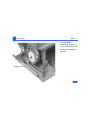
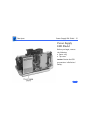
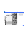
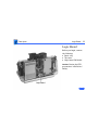
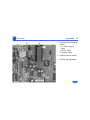
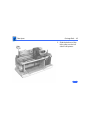
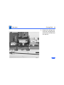
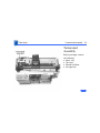
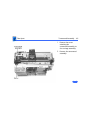
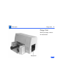
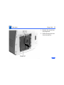
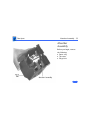
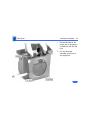
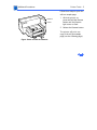
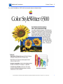
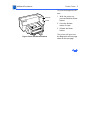
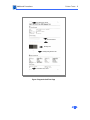
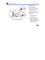
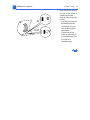
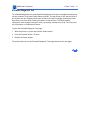
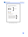
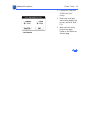
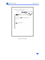
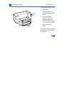
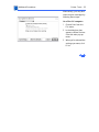
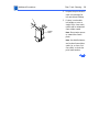
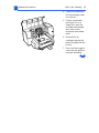
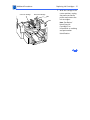
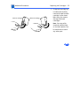
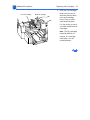
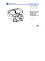
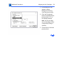
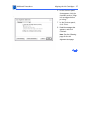
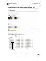
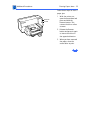
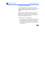
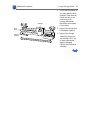
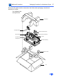
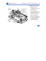
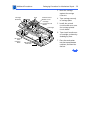
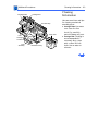
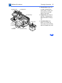
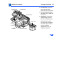
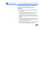
1
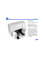
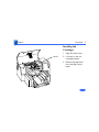
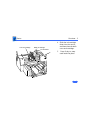
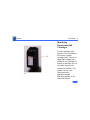
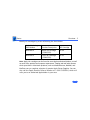
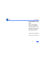
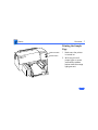
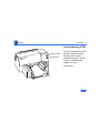
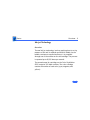
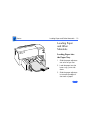
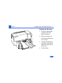
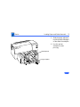
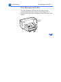
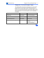
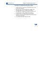
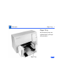
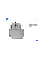
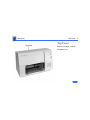
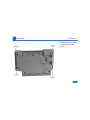
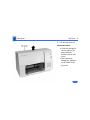
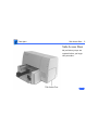
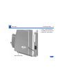
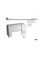
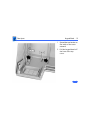
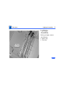
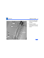
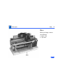
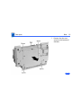
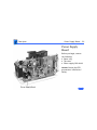
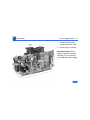
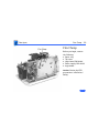
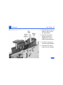
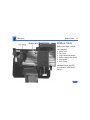
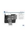
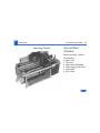
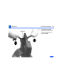
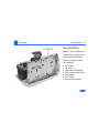
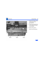
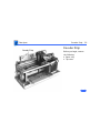
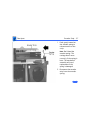
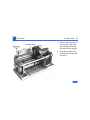
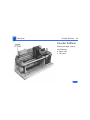
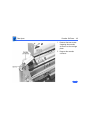
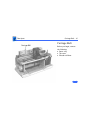
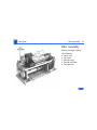
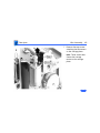
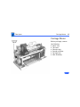
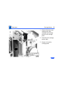
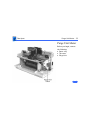
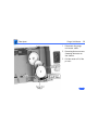
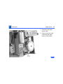
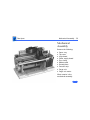
K Service Source
Color StyleWriter 6500
K Service Source
Basics
Color StyleWriter 6500
Basics
Overview - 1
Overview
The Color StyleWriter 6500
printer is a highperformance four-color
desktop color thermal inkjet printer for personal use.
It features high-resolution
documents, high-speed
printing (up to 8 pages per
minute (ppm) in black and
white and 4 ppm in color),
and built-in support for
computers running the Mac
OS, Windows 95, Windows
3.1 and DOS.
Basics
Overview - 2
Installing Ink
Cartridges
1
Latches
2
3
Open the front cover.
Lift both of the inkcartridge latches.
Remove the tape from
the cartridge’s print
head.
Basics
Overview - 3
4
Color ink cartridge
Black ink cartridge
5
Slide the ink cartridge
down into the carrier,
and then close the latch
over each cartridge.
Press firmly to snap
each latch into place.
Basics
Overview - 4
Identifying
Replacement Ink
Cartridges
The ink cartridges used
with the Color StyleWriter
6500 have a generic
cartridge label. There is no
Apple logo or Apple part
number on the cartridge. To
identify a cartridge, refer to
the small numeric part
number on the label. This
number can be crossreferenced to the
appropriate Apple
Marketing number in the
chart that follows.
Basics
Overview - 5
Identify ink cartridges by cross referencing the chart below.
Apple Marketing
Part Number
M5658G/A
M5659G/A
Product Description
HP Cartridge
Color Ink Cartridge
(CSW6500)
6105
Black Ink Cartridge
(CSW6500)
6104
Note: Apple ink cartridges can be found at most Apple authorized dealers, as well
as most office product and computer superstores. Catalog and mail order houses
which specialize in Macintosh products, such as MacWarehouse, MacMall, and
MacZone carry a complete selection of genuine Apple Printer Supplies. You can
also call the Apple Reseller Referral number at 1-800-538-9696, which will
refer you to an authorized Apple dealer in your area.
Basics
Overview - 6
Recommended Coated
Paper
Apple recommends Apple
Color Ink-Jet PREMIUM
PLUS Coated Paper. It is the
coated paper of choice to use
with the Color StyleWriter
6500 ink-jet printer.
• Letter size p/n M4792G/
A
• A4-size p/n M4791G/A.
Basics
Overview - 7
Printing the Sample
Page
Resume button
Power button
1
2
Make sure the printer
is turned on.
With the printer’s
power light on, press
and hold the resume
button until the orange
light goes out.
Basics
Overview - 8
Troubleshooting LEDs
Resume button
Power button
The Color StyleWriter 6500
has two LEDs, Power and
Resume, that can aid in
troubleshooting the printer.
See the Troubleshooting
chapter for more
information.
Basics
Overview - 9
Ink-jet Technology
Overview
Thermal ink-jet technology involves applying heat to a tiny
measure of ink until it expands and forms a bubble. As the
bubble continues to expand and burst, it is propelled
through one of the nozzles on the ink cartridge. This process
is repeated up to 8,000 times per second.
The monochrome ink cartridge on the Color StyleWriter
6500 contains 300 black nozzles. The color cartridge
contains 64 nozzles of each color (cyan, magenta, and
yellow).
Basics
Loading Paper and Other Materials - 10
Loading Paper
and Other
Materials
Loading Paper into
the Paper Tray
1
2
3
Slide the paper adjusters
out as far as you can.
Load the paper into the
lower tray, print side
down.
Slide the paper adjusters
in to touch the edges of
the stack of paper.
Basics
Loading Paper and Other Materials - 11
Printing an Envelope
1
2
3
4
Choose the appropriate
envelope size in the
printer software.
Slide an envelope into
the single-envelope slot
until it stops.
Load the envelope print
side down, with the flap
against the right side of
the printer.
Start printing.
Basics
Loading Paper and Other Materials - 12
Printing a Stack of
Envelopes
1
2
3
4
Choose the appropriate
envelope size in the
printer software.
Slide the paper adjusters
out as far as you can.
Put a stack of up to 15
envelopes in the printer.
Load the envelopes print
side down, with the flap
against the right side.
Basics
Loading Paper and Other Materials - 13
5
6
Width adjuster
Length adjuster
Slide the paper adjusters
in so they touch the edges
of the stack of envelopes.
Use the printer
software to start
printing.
Basics
Special Servicing Considerations - 14
Special Servicing Considerations
Default Settings
After replacing the logic board you must use the Color SW
6500 Default Settings Utility to download customer default
settings to the replacement logic board. The Color SW 6500
Default Settings utility is on the Companion CD (path:
Diagnostic Utilities/Color SW 6500 Utilities).
If the settings are not reset, the carriage will not center
when the access door is lifted, making it impossible for the
customer to insert/remove print cartridges. Therefore, it
is important for the printer to be set from “manufacturing
mode” to “customer mode” after a logic board is replaced.
Refer to Additional Procedures for more information.
Basics
Special Servicing Considerations - 15
X-Y Calibration
After replacing the logic board or mechanical assembly on a
Color StyleWriter 6500, you must use the Color SW 6500
X-Y Calibration utility to set factory default carriage values
in printer memory. The Color SW 6500 X-Y Calibration
utility is on the Companion CD (path: Diagnostic Utilities/
Color SW 6500 Utilities).
Refer to Additional Procedures for more information.
Capping Unit
If a Color StyleWriter 6500 printer is brought in for
service, and the customer has had the printer for awhile,
replace the purge unit (922-2912) which contains the
capping assembly.
Basics
Special Servicing Considerations - 16
Mechanical Assembly Screws
Important: Do not touch/remove the screws on the Color
StyleWriter 6500 mechanical assembly for any reason.
Doing so will put the printer out of alignment and will
require installing a new mechanical assembly.
K Service Source
Specifications
Color StyleWriter 6500
Specifications
Characteristics - 1
Characteristics
Marking engine
Speed
Four-color thermal ink jet engine
Actual speed depends on the documents printed and the computer
used
• Up to 8 pages per minute for black and white
• Up to 4 pages per minute for color
Black Test Print Speed:
Best: 4 pages per minute (ppm)
Normal: 7 ppm
Draft: 8 ppm
Color Print Speed:
Best: 1 page per minute (ppm)
Normal: 2 ppm
Draft: 4 ppm
Specifications
Graphics - 2
Graphics
Resolution
Best Black: 600 x 600 dpi (dots per inch)
Best Color: 300 x 300 dpi on recommended paper or on
transparencies (600 x 300 dpi on plain paper or coated
paper)
Normal Black: 300 x 300 dpi
Normal Color: 300 x 300 dpi
Draft Black: 300 x 300 dpi
Draft Color: 300 x 300 dpi
Specifications
Interfaces - 3
Interfaces
•
•
•
•
LocalTalk
High-speed serial RS-422 serial port
IEEE 1284B port supports Centronics parallel connection
EtherTalk support through the optional Apple StyleWriter
EtherTalk Adapter II
Specifications
Print Media - 4
Print Media
Paper Sizes
Paper Tray
Capacity
Plain paper, coated (recommended for color picture output)
LTR, LGL, Executive, A4, A5, B5
U.S. Letter (LTR): 8.5 x 11 in. (215.9 mm x 279.4 mm)
U.S. Legal (LGL): 8.5 x 14 in. (215.9 mm x 355.6 mm)
U.S. Executive: 7.25 x 10.5 in. (184.1 x 266.7 mm)
A4: 8.3 x 11.7 in. (210 mm x 297 mm)
A5: 5.8 x 8.3 in. (148.5 x 210 mm)
B5: 7.2 x 10.1 in. (182 x 257 mm)
Weight: 16-36 lbs.
Holds up to150 sheets of 20-pound paper, 15 envelopes, up to 30
cards, up to 50 transparencies, up to 25 sheets of paper labels
Specifications
Print Media - 5
Plain paper
Use 16-36 lb. paper
Labels
Accepts paper labels designed for inkjet printers
Envelopes
#10: 9.5 x 4.12 in. (241.3 x 104.4 mm)
U.S. #6: 6.5 in. x 3.625 in. (92.1 mm x 165.1 mm)
U.S. Monarch: 3.885 in. x 7.5 in. (98.4 mm x 190.05 mm)
DL: 4.33 x 8.66 in. (110 x 220 mm)
C6: 4.49 x 6.38 in. (114 x 162 mm)
A2: 4.375 x 5.75 in. (111 x 146 mm)
Weight: 20-24 lbs. Capacity: 20 envelopes
Specifications
Cards
Transparencies
- 6
Use 110 pound index maximum, 8.5 pt maximum
U.S. 4 x 6: 4 x 6 in. (101.6 x 152.4 mm)
U.S. 5 x 8: 5 x 8 in. (127 x 203.3 mm)
A6: 4.1 x 6 in. (105 x 148.5 mm)
Hagaki: 3.9 x 5.8 in. (100 x 148 mm)
Weight: 29-53 lbs. Capacity: 30 cards
Coated transparencies, most inkjet transparencies
Capacity: 50 sheets
Specifications
Printable Area - 7
Printable Area
Paper, Labels, &
Transparencies
U.S. Letter: 8.5 x 11 in. (215.9 mm x 279.4 mm)
Top margin: .04 in. (1.0 mm)
Bottom margin: .46 in. (11.7 mm)
Left & right margins: .25 in. (6.4 mm)
U.S. Legal: 8.5 x 14 in. (215.9 mm x 355.6 mm)
Top margin: .04 in. (1.0 mm)
Bottom margin: .46 in. (11.7 mm)
Left & right margins: .25 in. (6.4 mm)
U.S. Executive: 7.25 x 10.5 in. (184.1 x 266.7 mm)
Top margin: .04 in. (1.0 mm)
Bottom margin: .46 in. (11.7 mm)
Left & right margins: .25 in. (6.4 mm)
Specifications
Printable Area - 8
A4: 8.3 x 11.7 in. (210 mm x 297 mm)
Top margin: .04 in. (1.0 mm)
Bottom margin: .46 in. (11.7 mm)
Left & right margins: .13 in. (3.4 mm)
A5: 5.8 x 8.3 in. (148.5 x 210 mm)
Top margin: .04 in. (1.0 mm)
Bottom margin: .46 in. (11.7 mm)
Left & right margins: .13 in. (3.4 mm)
B5: 7.2 x 10.1 in. (182 x 257 mm)
Top margin: .46 in. (11.7 mm)
Bottom margin: .46 in. (11.7 mm)
Left & right margins: .13 in. (3.4 mm)
Specifications
Envelopes
Printable Area - 9
#10: 9.5 x 4.12 in. (241.3 x 104.4 mm)
Left margin: .87 in. (22 mm)
Top and Bottom margin: .125 in. (3.2 mm)
Right margin: .04 in. (1.0 mm)
DL: 4.33 x 8.66 in. (110 x 220 mm)
Left margin: .87 in. (22 mm)
Top and Bottom margin: .125 in. (3.2 mm)
Right margin: .04 in. (1.0 mm)
C6: 4.49 x 6.38 in. (114 x 162 mm)
Left margin: .87 in. (22 mm)
Top and Bottom margin: .125 in. (3.2 mm)
Right margin: .04 in. (1.0 mm)
Specifications
Cards
Printable Area - 10
U.S. 4 x 6: 4 x 6 in. (101.6 x 152.4 mm)
Top margin: 0.04 in. (1 mm)
Bottom margin: .46 in. (11.7 mm)
Left & right margins: 0.125 in. (3.2 mm)
U.S. 5 x 8: 5 x 8 in. (127 x 203.3 mm)
Top margin: 0.04 in. (1 mm)
Bottom margin: .46 in. (11.7 mm)
Left & right margins: 0.125 in. (3.2 mm)
A6: 4.13 x 6 in. (105 x 148.5 mm)
Top margin: 0.04 in. (1 mm)
Bottom margin: .46 in. (11.7 mm)
Left & right margins: 0.125 in. (3.2 mm)
Hagaki: 3.9 x 5.8 in. (100 x 148 mm)
Top margin: 0.04 in. (1 mm)
Bottom margin: .46 in. (11.7 mm)
Left & right margins: 0.125 in. (3.2 mm)
Specifications
Ink Cartridges - 11
Ink Cartridges
Dual- Cartridge Ink
System
Color Ink
Cyan, Magenta, and Yellow
Part number M5659G/A
Black Color
Black ink
Part number M5658G/A
Ink Cartridge Life
Color Ink Cartridge
Black Ink Cartridge
460 pages (15% coverage on Letter/A4 page)
840 pages (5% coverage on Letter/A4 page)
Note: Actual results may vary depending on the print media, quality
selected, and the amount of ink coverage on each printed page.
Specifications
Environmental - 12
Environmental
Temperature
Operating: 41–104°F (5-40°C)
Storage: -40-140°F (-40-60°C)
Humidity
10–80% (noncondensing)
Specifications
Electrical - 13
Electrical
Electrical
Requirements
Power Consumption
AC power adapter
100 to 240 VAC ± 10%
50 to 60 Hz (±3Hz)
Powered Off (plugged in): 1 W
Powered On (non-printing): 5.5 W
Powered On (printing): 48 W
Specifications
Physical - 14
Physical
Dimensions
Weight
Height: 8.9 in. (226 mm)
Width: 17.5 in. (444 mm)
Depth: 15.6 in. (396 mm)
14.3lb (6.5 kg)
K Service Source
Troubleshooting
Color StyleWriter 6500
Troubleshooting
General /- 1
General
The Symptom Charts included in this chapter will help you
diagnose specific symptoms related to your product. Because cures
are listed on the charts in the order of most likely solution, try
the first cure first. Verify whether or not the product continues to
exhibit the symptom. If the symptom persists, try the next cure.
(Note: If you have replaced a module, reinstall the original module
before you proceed to the next cure.)
If you are not sure what the problem is, or if the Symptom Charts
do not resolve the problem, refer to the Flowchart for the product
family.
For additional assistance, contact Apple Technical Support.
Troubleshooting
Error Messages and LEDs/ - 2
Error Messages and LEDs
The Color StyleWriter 6500 has two LEDs that can aid in
troubleshooting the printer: Resume LED and Power LED. To
interpret these LEDs, refer to Symptom Charts/LEDs later in this
chapter.
Resume
Power
Troubleshooting
Error Messages and LEDs /- 3
The printer software also gives error messages to pinpoint
errors.
Make sure the printer is hooked up to a Macintosh and that the
Color StyleWriter 6500 printer driver software is installed.
Troubleshooting
Diagnostic Tests and Sample Pages/ - 4
Diagnostic Tests and Sample Pages
The following table summarizes the diagnostic tests and sample
pages that you can run using the Power and Resume buttons.
Perform the tests with printer power on and plain paper in the
paper tray; press and hold down the Power button while pressing
the Resume button. For more information, refer to Additional
Procedures.
Diagnostic Test/Printout
Power Button
Resume Button
Sample Page
HOLD DOWN
Press once (hold briefly)
Diagnostic Self Test
HOLD DOWN
Press 5 times
Extended Diagnostic Test
HOLD DOWN
Press 12 times
Clean Print Heads/Ink Cartridges
HOLD DOWN
Press 7 times (standard
cleaning)
Press 8 times (deep cleaning)
Press 9 times (priming)
Troubleshooting
Standard Troubleshooting Procedure/ - 5
Standard Troubleshooting Procedure
1
2
3
4
5
Visually inspect the printer for any potential cause for the
printer to be returned.
Run Printer Self-Test and evaluate print quality. (See
preceding page or refer to Additional Procedures.)
Run Diagnostic Test pages and evaluate print quality. (See
preceding page or refer to Additional Procedures.)
Connect printer to compute. Run the Color SW 6500
Utilities to verify the printer properly received the signals
and prints the test pages.
Try a known good printer cable and retest.
Troubleshooting
Symptom Charts/Operation - 6
Symptom Charts
Operation
No power
1
2
3
4
5
Check power cable connections and recycle power to printer.
Replace power adapter and retest.
Reseat logic board connectors and retest. If problem
continues replace logic board.
Check that Power and Resume buttons are not stuck on
keypad cover.
Replace lightpipe assembly and retest.
Troubleshooting
Symptom Charts /Operation- 7
Does not print
1
2
3
4
5
6
Refer to LEDs later in this chapter.
Turn on printer and restart computer.
Check interface cable and connector. Replace interface cable.
Open Chooser and verify correct printer driver and port.
Replace printer driver.
Reseat logic board connectors. Replace logic board.
I/O failure
1
2
3
Check interface cable and connector.
Replace interface cable.
Reseat logic board connectors. Replace logic board.
Troubleshooting
Carriage collides
with left side
Symptom Charts/Operation - 8
1
2
3
4
5
6
7
Make sure white plastic clutch actuator is not interfering
with carriage movement. If necessary, reseat clutch
actuator. See “Fixing Carriage Stalls” in Additional
Procedures for location of clutch actuator.
Remove obstructions from carriage and paper paths.
Clean excessive ink or oil from encoder strip, carriage
assembly, and carriage path components.
Be sure encoder strip stiffner is in place. Replace encoder
strip.
Reseat logic board connectors. If problems continue, replace
logic board.
Check mechanical assembly for damage and proper operation.
Replace faulty or damaged mechanical assembly.
Troubleshooting
Carriage collides
with right side
Symptom Charts/Operation - 9
1
Make sure purge unit does not interfere with carriage
movement.
2 Manually slide carriage. Remove obstructions from carriage
and paper paths.
3 Replace any part interfering with carriage movement.
4 Reseat logic board connectors. If problem continues, replace
logic board.
5 Check carriage motor cable connection.
6 Replace carriage motor.
7 Check purge unit motor. Verify purge unit motor is
connected. If connected, replace the purge unit motor.
8 Reseat the ribbon carriage cable. If problem continues,
replace the ribbon carriage cable.
9 Check mechanical assembly for damage and proper operation.
10 Replace faulty or damaged mechanical assembly.
Troubleshooting
Symptom Charts/Operation - 10
Ink cartridge won’t
lock in carriage
1
2
3
4
Verify correct ink cartridge for the printer. Refer to Basics.
Replace ink cartridge.
Remove and reinstall purge unit. If faulty replace purge unit.
Replace mechanical assembly.
No print or printer
locks up
1
Recycle power to the printer. Sometimes this requires
unplugging the printer from the wall.
Reseat logic board connectors and retest. If problems
continue, replace logic board.
Replace mechanical assembly.
2
3
Stops printing
1
2
3
4
5
6
Make sure clutch actuator is not interfering with carriage
movement.
Remove obstructions from carriage and paper paths.
Replace any part interfering with carriage movement.
Reseat logic board connectors and retest.
Replace logic board.
Replace carriage motor and retest.
Troubleshooting
Symptom Charts/Operation - 11
7
8
Replace mechanical assembly.
Replace the power supply board and retest.
Short pen life
1
2
3
4
Check that tape is not covering the print cartridge.
Replace ink cartridge.
Inspect and clean purge unit area. Retest.
Replace purge unit.
Erratic or slow
movement
1
2
Visually inspect the mechanism for obstructions.
Remove and clean the print cartridge contacts. Try using the
print cartridge in another printer. If problem continues
with the other printer, replace the print cartridge.
Perform “Fiber Track Cleaning” in Additional Procedures.
Replace the power supply board. Retest.
Inspect the carriage belt for frays, cuts, or other damage.
Check mechanical assembly for damage and proper operation.
Replace the mechanical assembly.
Reseat logic board connectors and retest.
3
4
5
6
7
8
Troubleshooting
Rejects cartridge
Symptom Charts/Operation - 12
1
2
3
4
5
6
7
Leaky cartridge
1
2
3
4
5
6
Remove tape on ink cartridge. Retest.
Remove and clean the print cartridge contacts. Try using the
print cartridge in another printer.
Perform “Print Head Cleaning” in Additional Procedures.
Replace ink cartridge.
Remove/reinstall flexible ribbon carriage cable.
Replace mechanical assembly.
Reseat logic board connectors. Replace logic board.
Clean ink damaged parts. Replace ink damaged parts. Note:
Apple does not support damage from the use of refilled ink
cartridges.
Replace ink cartridge.
Replace mechanical assembly.
Inspect and clean purge unit. Replace purge unit.
Reseat logic board connectors. Replace logic board.
Verify purge unit motor cable is connected. If connected,
replace purge unit motor.
Troubleshooting
Grinding, squeaking
or scraping noise
Symptom Charts /Operation- 13
1
2
Clean and inspect the printer.
Manually slide carriage. Remove obstructions from carriage
and paper paths.
3 Replace mechanical assembly. Retest.
4 Inspect and replace frayed or cut carriage belt.
5 Replace mechanical assembly.
6 Replace paper feed motor. Retest.
7 Replace drive gear. Retest.
8 Replace pivot spring. Retest.
9 Replace purge unit motor. Retest.
10 Replace carriage motor. Retest.
11 Remove pressure plate and check for obstructions.
12 Reseat logic board connectors. Replace logic board.
Troubleshooting
Knocking or clicking
noise
Symptom Charts/Operation - 14
1
2
3
4
5
Paper feeds
continuously
1
2
3
4
5
Clean and inspect the printer.
Manually slide carriage. Remove obstructions from carriage
and paper paths.
Inspect and replace frayed or cut carriage belt.
Check mechanical assembly for damage and proper operation.
Replace faulty or damaged mechanical assembly.
Replace carriage motor.
Verify that paper-out actuator is properly positioned to the
sensor on the logic board.
Verify no obstruction is interfering with the pressure plate
operation. Replace the pressure plate and retest.
Verify the carriage assembly slides to the clutch actuator and
the clutch actuator engages the clutch (left side of carriage).
If faulty, replace the mechanical assembly.
Verify paper motor is connected to the logic board. If
connected, replace the paper motor.
Reseat logic board connectors. Replace logic board.
Troubleshooting
Burning smell
No trouble found
Symptom Charts/Operation - 15
1
2
3
4
Visually inspect motors. Replace damaged motors.
Reseat logic board connectors. If problems continue, replace
logic board.
Replace the power supply board.
Replace mechanical assembly.
1
2
Run Self Tests. Refer to Additional Procedures.
Perform Diagnostic Tests. Refer to Additional Procedures.
Troubleshooting
Symptom Charts/Paper - 16
Paper
Paper sticks together
1
2
3
4
5
6
7
8
Paper skews
1
2
3
Fan paper and remove excess sheets from paper tray.
Verify that media meets specifications.
Stack media against right wall of In Tray.
Verify that paper-out actuator contacts sensor board. If not,
replace actuator.
If actuator does contact sensor board, replace board.
Remove pressure plate and check for obstructions.
Replace pressure plate.
Replace mechanical assembly.
Perform diagnostic test to verify that print skew is out of
specification. Refer to Additional Procedures.
Inspect paper tray. Make sure it’s firmly installed. Replace
and retest. Note: If margin on left side of page gets larger,
cause is likely the input tray.
Inspect width adjuster. Make sure width adjuster is against
Troubleshooting
Symptom Charts/Paper - 17
4
Paper jams
1
2
3
4
5
6
the media. Replace and retest. Note: If margin on left side of
paper gets smaller, cause is likely the chassis or other
mechanical part.
Replace the mechanical assembly.
Remove media from paper path.
Verify media meets printer’s paper specifications. Note: If
sticky labels are stuck in the mechanism, the mechanism
will have to be replaced.
Verify the carriage assembly slides to the clutch actuator and
the clutch actuator engages the clutch (left side of carriage).
If faulty, replace the mechanical assembly.
Check paper feed motor connection. If connected, replace
paper feed motor.
Remove paper tray. Replace if necessary.
Replace mechanical assembly.
Troubleshooting
Symptom Charts/Paper - 18
Paper doesn’t load
completely
1
2
3
4
5
Remove paper tray and check for obstructions.
Clean drive rollers. Use water on a clean lint-free cloth.
Replace paper tray.
Replace mechanical assembly.
Reseat logic board connectors. Replace logic board.
Paper doesn’t eject
1
2
Remove and reinstall paper tray.
Inspect “wings” to be sure they are properly and completely
installed. Refer to the Exploded View for wing locations.
Remove media from paper path.
Verify media meets specifications.
Inspect clutch actuator to see that it moves freely. See
“Fixing Carriage Stalls” in Additional Procedures for
location.
Replace mechanical assembly.
3
4
5
6
Troubleshooting
Paper feeds
continuously
Symptom Charts/Paper - 19
1
2
3
4
Multiple pickup
1
2
3
4
Remove and reinstall the paper tray.
Verify the carriage assembly can slide to the clutch actuator
and that the clutch actuator can engage the clutch (left side of
carriage). Replace the mechanical assembly.
Remove media from the paper path. Verify media meets
specifications.
Replace mechanical assembly.
Verify media is lined up against the right wall of the paper
tray. Verify the paper meets the printer’s media
specifications.
Remove and reinstall paper tray. Retest.
Clean the encoder strip with water. Replace is necessary.
Replace the mechanical assembly.
Troubleshooting
Symptom Charts/Print Quality - 20
Print Quality
Missing dots
1
2
3
4
5
6
Perform “Fiber Track Cleaning” in Additional Procedures.
Perform “Print Head Cleaning” in Additional Procedures.
Make sure ink cartridges are set firmly.
Use only specified paper, envelopes, transparencies.
Replace ink cartridge. See Additional Procedures chapter.
Reseat logic board connectors. Replace logic board.
Carriage moves but
printer doesn’t print
1
2
3
4
5
Make sure the tape is removed from the ink cartridge.
Remove and clean the print cartridge contacts.
Perform “Print Head Cleaning” in Additional Procedures.
Replace ink cartridge. See Additional Procedures.
Reseat logic board connectors. If problem continues, replace
logic board.
Replace mechanical assembly.
6
Troubleshooting
Symptom Charts/Print Quality - 21
Incomplete print
1
2
3
4
5
Remove tape on ink cartridge. Replace the ink cartridge.
Clean the print cartridge contacts.
Perform “Print Head Cleaning” in Additional Procedures.
Reseat logic board connectors. Replace logic board.
Replace mechanical assembly.
Blurring or fuzzy
printing
1
Clean the fibers from the carriage assembly. Perform
“Fiber Track Cleaning” in Additional Procedures.
Look for obstruction interfering with the carriage
movement. Replace the mechanical assembly.
Remove and reseat interface cable.
Reseat logic board connectors. Replace logic board.
Perform “Print Head Cleaning” in Additional Procedures.
Replace ink cartridge.
Replace mechanical assembly.
2
3
4
5
6
7
Troubleshooting
Underlines or streaks
Symptom Charts/Print Quality - 22
1
2
3
4
5
6
Prints wrong color
1
2
3
4
Black and white is
printing instead of
color
1
Replace ink cartridge and retest.
Reseat the flexible ribbon carriage cable. Replace the cable.
Perform “Fiber Track Cleaning” in Additional Procedures.
Perform “Print Head Cleaning” in Additional Procedures.
Reseat all logic board connectors. If problem continues,
replace the logic board.
Check operation of mechanical assembly. If damaged, replace
mechanical assembly.
Perform “Print Head Cleaning” in Additional Procedures.
Replace ink cartridge. See Additional Procedures.
Reseat all logic board connectors. If problem continues,
replace the logic board.
Replace mechanical assembly.
Check print settings. Make sure the “Print is Grayscale”
option is not selected and that other color options are
specified correctly.
Troubleshooting
Printer Fails SelfTests
Symptom Charts/Print Quality - 23
1
2
3
4
5
Vertical Misalignment
1
2
Perform “Fiber Track Cleaning” in Additional Procedures.
Perform “Print Head Cleaning” in Additional Procedures.
Replace ink cartridge. See Additional Procedures.
Reseat all logic board connectors. If problem continues,
replace the logic board.
Check operation of mechanical assembly. If damaged, replace
mechanical assembly.
Check for oil or excessive ink on encoder strip. Clean the
encoder strip with water. If necessary, replace the encoder
strip.
Clean and inspect the mechanism. If the mechanism cause
printer related problems, replace the mechanism.
Troubleshooting
Symptom Charts/LEDs - 24
LEDs
Power and Resume
lights off
1
2
3
4
5
Check power connections and power source.
Recycle power to printer.
Replace power cord.
Replace power board and retest.
Reseat logic board connectors. Replace logic board.
Power and Resume
lights blinking in
unison, printer
won’t print
1
2
3
Verify printer has paper and ink cartridges.
Make sure ink cartridges are properly seated.
Visually inspect the paper-out sensor. Verify the sensor is
properly positioned to the flag sensor on the logic board.
Reseat logic board connectors. Replace logic board.
Replace the carriage motor. Retest
4
5
Troubleshooting
Power and Resume
lights flashing
alternately, printer
won’t print
Symptom Charts/LEDs - 25
1
2
3
4
Make sure the top cover is closed.
Verify printer connections.
Verify proper printer driver and printer port are selected.
Perform printer self tests. Refer to “Printer Tests” in
Additional Procedures.
5 Replace printer cable.
6 Reseat logic board connectors. Replace logic board.
7 Verify that paper-out actuator contacts sensor on the logic
board. If not, replace actuator.
8 Replace mechanical assembly.
9 Look for oil or excessive ink on the encoder strip. Clean the
encoder strip with water. Replace if necessary.
10 Replace the carriage motor.
11 Refer to “Carriage Stall” in Additional Procedures.
Troubleshooting
Power and Resume
lights on steady,
printer won’t print
Symptom Charts/LEDs - 26
1
2
3
4
5
6
Power light on but
Resume light
flashing, printer
won’t print
1
2
3
4
5
Try recycling power to printer.
Check that correct printer driver is selected.
Replace the printer cable, retest.
Check the clutch actuator. Make sure it’s free from
obstructions and moves freely. See “Fixing Carriage Stalls”
in Additional Procedures for clutch location.
Reseat logic board connectors. Replace logic board.
Replace mechanical assembly.
Install media. Make sure media is not buckled in IN tray and
paper length and width adjusters are firmly against media
stack.
Check for paper jam. See Additional Procedures.
Install ink cartridge or replace empty ink cartridge. Make
sure ink cartridge snaps into place and cover is closed. Refer
to “Cleaning Paper Jams” in Additional Procedures.
Reseat ink cartridge.
Press Resume button. Page should print and eject to OUT tray.
Troubleshooting
No Lights
Symptom Charts/LEDs - 27
1
2
Reseat logic board connectors and retest. If problems
continue, replace the logic board.
Replace the power supply and retest.
K Service Source
Take Apart
Color StyleWriter 6500
Take Apart
Paper Tray - 1
Paper Tray
No preliminary steps are
required before you begin
this procedure.
Take Apart
Paper Tray - 2
1
2
Compress the latch
underneath the paper
tray.
Slide out the paper tray
and remove it from the
printer.
Take Apart
Top Cover - 3
Top Cover
Before you begin, remove
the paper tray.
Take Apart
Top Cover - 4
1
Note: Position the
parallel port I/O clips so
they will not catch on the
top cover when you lift
it off.
Remove the two screws
from the top cover.
Take Apart
Top Cover - 5
2
Release the four latches
on the bottom of the
printer.
Take Apart
Top Cover - 6
3
Lift the top cover off.
Replacement Note:
• Push the carriage to
the far right so you
don’t catch the
flexible cable on the
cover.
• Take care not to
damage the light pipe
on the inside of the
top cover.
Take Apart
Access Door - 7
Access Door
No preliminary steps are
required before you begin
this procedure.
Note: Remove the ink
cartridges at this point if
they are still in the printer.
Take Apart
Access Door - 8
1
Pull the access door off
of the two hinges on the
top cover.
Take Apart
Side Access Door - 9
Side Access Door
No preliminary steps are
required before you begin
this procedure.
Take Apart
Side Access Door - 10
1
I nsert a small flatblade
screwdriver into latch to
release the access door.
Take Apart
Keypad Bezel - 11
Keypad Bezel
Before you begin, remove
the following:
• Paper tray
• Top cover
Take Apart
Keypad Bezel - 12
1
2
Spread the two latches on
the inside of the cover
outward.
Pull the keypad bezel off
the front of the top
cover.
Take Apart
Lightpipe Assembly - 13
Lightpipe
Assembly
Before you begin, remove
the following:
• Paper tray
• Top cover
Take Apart
Lightpipe Assembly - 14
1
2
Lift up on the two clear
latches on the lightpipe
assembly.
Slide the assembly
toward you to force it out
from under the retaining
latches.
Take Apart
Base - 15
Base
Before you begin, remove
the following:
• Paper tray
• Top cover
Take Apart
Base - 16
1
Remove the four torx
screws on the bottom of
the base.
Take Apart
Base - 17
2
3
Use a flat blade
screwdriver to press in
on the chassis clamp tab.
Remove the clamp from
the base.
Take Apart
Base - 18
4
5
Remove the mechanical
assembly by sliding the
chassis to the left and
aligning the tabs.
Lift the mechanical
assembly from the base.
Take Apart
Logic Board EMI Shield - 19
Logic Board EMI
Shield
Before you begin, remove
the following:
• Paper tray
• Top cover
Caution: Review the ESD
precautions in Bulletins/
Safety.
Take Apart
Logic Board EMI Shield - 20
1
2
Remove the four screws
from the logic board
EMI shield.
Remove the logic board
EMI shield from the
printer.
Take Apart
Power Supply EMI Shield - 21
Power Supply
EMI Shield
Before you begin, remove
the following:
• Paper tray
• Top cover
Caution: Review the ESD
precautions in Bulletins/
Safety.
Take Apart
Power Supply EMI Shield - 22
1
2
Remove the two torx
screws from the power
supply EMI shield.
Remove the power
supply EMI shield.
Take Apart
Logic Board - 23
Logic Board
Before you begin, remove
the following:
• Paper tray
• Top cover
• Logic board EMI shield
Caution: Review the ESD
precautions in Bulletins/
Safety.
Take Apart
Logic Board - 24
Note: The NVRAM on the
logic board contains the
information used to set the
“customer mode”, and
carriage XY calibration.
Replacing the logic board or
mechanical assembly
requires re-calibration of
the printer.
See “Default Settings” and
“X-Y Calibration” in
Additional Procedures for
more information.
Take Apart
Logic Board - 25
1
2
3
Disconnect the following
cables:
• J1: Power supply
cable
• J2:Flex cable
• J4:Motor cable
Remove the two screws.
Remove the logic board.
Take Apart
Power Supply Board - 26
Power Supply
Board
Before you begin, remove
the following:
• Paper tray
• Top cover
• Power supply EMI shield
Caution: Review the ESD
precautions in Bulletins/
Safety.
Take Apart
Power Supply Board - 27
1
2
Disconnect the power
supply cable from CN3
Remove the six screws.
Replacement Note: Don’t
forget to replace the paper
shielding (if you removed
it) behind the power supply.
Take Apart
Flex Clamp - 28
Flex Clamp
Before you begin, remove
the following:
• Paper tray
• Top cover
• Logic board EMI shield
• Power supply EMI shield
• Logic board
Caution: Review the ESD
precautions in Bulletins/
Safety.
Take Apart
Flex Clamp - 29
1
2
3
4
Press the tab on the flex
clamp so that it clears
the ground plane.
Move the access door
actuator so that the
flagged end is up and
clears the ground plane.
Pull the flex clamp up
and off the ground plane.
Disconnect the ribbon
cable from the carriage.
Take Apart
Ribbon Cable - 30
Ribbon Cable
Before you begin, remove
the following:
• Paper tray
• Top cover
• Logic board EMI shield
• Power supply EMI shield
• Logic board
• Flex Clamp
Caution: Review the ESD
precautions in Bulletins/
Safety.
Take Apart
Ribbon Cable - 31
1
2
3
Remove the foam from
the flex clamp.
Lift the ribbon cable off
the two posts and two
tabs.
Slide the ribbon cable to
the right, moving the
cable from underneath
the large black tab.
Take Apart
Access Door Actuator - 32
Access Door
Actuator
Before you begin, remove
the following:
• Paper tray
• Top cover
• Logic board EMI shield
• Power supply EMI shield
• Logic board
• Flex clamp
Take Apart
Access Door Actuator - 33
1
Push the access door
actuator down and out of
the retaining hinges on
the flex clamp.
Take Apart
Ground Plane - 34
Ground Plane
Note: It’s only necessary to
remove the ground plane if
replacing the mechanism.
Before you begin, remove
the following:
• Paper tray
• Top cover
• Logic board EMI shield
• Power supply EMI shield
• Logic board
• Flex clamp
• Access Door Actuator
Take Apart
Ground Plane - 35
1
2
3
Remove the three screws
from the top of the
ground plane.
Slide the ground plane up
over the tabs on the top
of the chassis.
Remove the ground
plane from the printer.
Take Apart
Encoder Strip - 36
Encoder Strip
Before you begin, remove
the following:
• Paper tray
• Top cover
Take Apart
Encoder Strip - 37
1
2
Push gently inward on
the encoder spring to
release tension on the
strip.
Note: Don’t bend the
encoder spring. The
carriage won’t move
correctly if the spring is
bent. The mechanical
assembly will need
replacement if the
spring is damaged.
Disconnect the encoder
strip from the encoder
spring.
Take Apart
Encoder Strip - 38
3
4
Remove the other side of
the encoder strip from
the retaining tab on the
left side of the carriage.
Slide the encoder strip
through the carriage and
remove it.
Take Apart
Encoder Stiffener - 39
Encoder Stiffener
Before you begin, remove
the following:
• Paper tray
• Top cover
Take Apart
Encoder Stiffener - 40
1
2
Remove the two screws
fastening the encoder
stiffener to the carriage
plate.
Remove the encoder
stiffener.
Take Apart
Carriage Belt - 41
Carriage Belt
Before you begin, remove
the following:
• Paper tray
• Top cover
• Encoder stiffener
Take Apart
Carriage Belt - 42
1
Push in on the
turnaround pulley
assembly on the right
side of the printer.
Take Apart
Carriage Belt - 43
2
Slide the belt out of the
idler pulley on the left
side of the printer.
Take Apart
Carriage Belt - 44
3
Detach the carriage belt
from the carriage board
and remove the belt from
the printer.
Take Apart
Turnaround Assembly - 45
Turnaround
Assembly
Before you begin, remove
the following:
• Paper tray
• Top cover
• Encoder stiffener
• Carriage belt
Take Apart
Turnaround Assembly - 46
1
2
Remove the screw
attaching the
turnaround assembly to
the carriage assembly.
Remove the turnaround
assembly.
Take Apart
Idler Assembly - 47
Idler Assembly
Before you begin, remove
the following:
• Paper tray
• Top cover
• Encoder strip
• Encoder stiffener
• Carriage belt
Take Apart
Idler Assembly - 48
1
Remove the two screws
attaching the idler mount
to the carriage plate.
Note: These screws also
fasten the carriage
motor to the carriage
plate.
Take Apart
Carriage Motor - 49
Carriage Motor
Before you begin, remove
the following:
• Paper tray
• Top cover
• Encoder strip
• Encoder stiffener
• Carriage belt
• Idler assembly
Take Apart
Carriage Motor - 50
1
2
3
Remove the two screws
attaching the idler
assembly and carriage
motor to the carriage
plate.
Disconnect the carriage
motor cable.
Remove it from the
carriage plate.
Take Apart
Purge Unit - 51
Purge Unit
Before you begin, remove
the access door.
Take Apart
Purge Unit - 52
1
2
Remove the screw from
the purge unit.
Slide the purge unit out
from the printer.
Take Apart
Absorber Assembly - 53
Absorber
Assembly
Before you begin, remove
the following:
• Paper tray
• Top cover
• Purge Unit
Take Apart
Absorber Assembly - 54
1
2
Release the tabs on the
purge unit by pressing a
screwdriver into the tab
hole.
Pull the absorber
assembly up and out of
the purge unit.
Take Apart
Purge Unit Motor - 55
Purge Unit Motor
Before you begin, remove
the following:
• Paper tray
• Top cover
• Purge Unit
Take Apart
Purge Unit Motor - 56
1
2
3
Disconnect the purge
unit motor cable.
Removing the two screws
fastening the motor to
the chassis.
Pull the motor off of the
printer.
Take Apart
Paper Motor - 57
Paper Motor
Before you begin, remove
the following:
• Paper tray
• Top cover
• Base
Note: If you use a small
screwdriver, you don’t need
to remove the base.
Take Apart
Paper Motor - 58
1
2
Disconnect the paper
motor cable.
Remove the two screws
connecting the paper
motor to the printer.
Take Apart
Mechanical Assembly - 59
Mechanical
Assembly
Remove the following:
• Paper tray
• Top cover
• Logic board
• Power supply board
• Flex clamp
• Ribbon cable
• Ground plane
• Encoder strip
• Purge unit
• Purge unit motor
What remains is the
mechanical assembly.
Take Apart
Mechanical Assembly - 60
Important: Never adjust any screws on the mechanical
assembly. Doing so will require replacement of the
mechanical assembly.
Note: The NVRAM on the logic board contains the
information used to set the “customer mode” Default
Settings, and carriage XY calibration. Replacing the logic
board or mechanical assembly requires re-calibration of
the printer.
See “Default Settings” and “X-Y Calibration” in Additional
Procedures for procedures.
K Service Source
Additional Procedures
Color StyleWriter 6500
Additional Procedures
Printer Tests - 1
Printer Tests
Self Test
The self test contains text, graphics, and an image. It
gives you a quick view of the output the customer is
seeing. In general, if the self test prints out OK and looks
OK, the printer is probably fine.
Additional Procedures
Printer Tests - 2
Follow these steps to print the
self test sample page.
1
Resume
Power
2
With the printer on,
press and hold the Resume
button until the Resume
light starts to flash.
Release the Resume button.
The printer will print one
copy of the self test sample
page (see the following page).
Figure: Power and Resume Buttons
Additional Procedures
The Color StyleWriter 6500 self test sample page is shown below.
Printer Tests - 3
Additional Procedures
Printer Tests - 4
Diagnostic Self-Test
The diagnostic test contains a skew test, a print cartridge
test, and a left/right registration test and displays
selected printer information. The skew test is
particularly useful, but the print cartridge information
in not as extensive as the extended diagnostic or final test.
Additional Procedures
Printer Tests - 5
To print the diagnostic selftest:
1
Resume
Power
2
3
Figure: Power and Resume Buttons
With the printer on,
press and hold the Power
button.
Press the Resume
button 5 times.
Release the Power
button.
The printer will print out
the diagnostic self-test page
shown on the next page.
Additional Procedures
Printer Tests - 6
Print Skew Test, Upper
Nozzle Patterns
Banding Test
Left/Right Registration Test
Print Skew Test, Lower
Figure: Diagnostic Self-Test Page
Additional Procedures
Printer Tests - 7
Interpreting the Diagnostic Test
All interpretations refer to the Diagnostic Self-Test Page shown on the preceding page.
Printer Information
• Model: The model name indicates the model of the printer (such as the Color StyleWriter
6500) and the model number provides the part number of the printer.
• Revision: Revision notes the firmware version installed.
• ID: Printer identification number.
• Cartridge Status: Indicates the status of the print cartridge.
• Flash: Indicates whether PCA programmable part are included
• I/O Connection: I/O identifies printer port status.
Additional Procedures
Printer Tests - 8
Interpreting the Diagnostic Test (Continued)
Print Cartridge
• Nozzle Patterns: The black and colored nozzle test patterns verify that dots on each print
cartridge are firing correctly. If dots are missing, refer to the “Print Quality” section in
Troubleshooting.
• Banding Test: If the nozzle test passes, the dark patches of the banding test should be
relatively smooth and uniform. Horizontal bands of lighter and darker areas indicate line feed
errors from drag, worn mechanical parts, or cartridge errors.
• Left/Right Registration Test: The left/right registration test measures the printer’s ability to
print a smooth vertical line. Half of the line is printed while the carriage moves to the left, the
other half, while the carriage moves to the right. The line should be straight without gaps;
otherwise, the encoder strip, carriage motor, drive belt, paper motor, or main logic board could
be damaged.
• Print Skew Test: The print skew test measures the print margins to ensure the paper moves
through the printer properly and printing does not appear tiltled.
Additional Procedures
Printer Tests - 9
Print Skew Test
A
A
OUT
C
Figure: Print Skew Test Page
C
C
A
IN
The Print Skew test
measures the print margins
to ensure that paper moves
through the printer
properly and printing does
not appear tilted. To test for
print skew:
1
2
Print the Diagnostic
Self-Test page.
Fold the top edge of the
page down towards the
bottom, aligning the left
edge of the paper without
creasing the paper.
Additional Procedures
Printer Tests - 10
3
A
A
OUT
C
C
C
A
IN
Note where the vertical
line left of the A falls in
relation to the two
vertical lines to the left
of the C.
• If the single vertical line
falls between the two
vertical lines, the print
skew is within product
specification.
• If these lines do not
match up, print skew is
out of specification. See
“Print Skew” in
Troubleshooting.
Additional Procedures
Printer Tests - 11
Extended Diagnostic Test
The extended diagnostic test show detailed information on the print cartridges and also prints
out the contents of the Non-Volatile Memory (NVM). The top section of the test will show if
any nozzles are out. Random nozzle outs are due to the print cartridge; cleaning will often
clear them (see Print Head Cleaning Procedure in this section). The NVM contains
information such as page count, pen count, xy settings, and last error trap. The test prints
this information in hexadecimal format.
To print the Extended Diagnostic Test page:
1
With the printer on, press and hold the Power button.
3
Release the Power button.
2
Press the Resume button 12 times.
The printer will print out the Extended Diagnostic Test page shown on the next page.
Additional Procedures
Printer Tests - 12
Nozzle Patterns
NVM
Figure: Extended Diagnostic Test Page
Additional Procedures
Printer Tests - 13
Interpreting the Extended Diagnostic Test
All interpretations refer to the Extended Diagnostic Test Page shown on the preceding page.
Print Cartridge
• Nozzle Patterns: Check the black and color nozzle patterns for any poor print quality. The top
section of the test will show if any nozzles, primitive (blocks), or addresses (ladders) are out.
Check the “stair-step” patterns for missing dots (gaps in the diagonal lines).
Check each primitive and address to determine whether or not any addresses or
primitives are missing. A missing primitive (seen as a box missing in the pattern) or
a missing address (seen as a missing column of horizontal lines) will cause 12 to 22
nozzles to drop out.
Missing nozzles can be caused by bad print cartridges, incorrectly installed print
cartridges, mis-aligned purge units, a bad mechanical assembly. First try cleaning the
cartridges. If that does not solve the problem, try replacing the flexible ribbon cable,
or the mechanical assembly.
Additional Procedures
Printer Tests - 14
Interpreting the Extended Diagnostic Test (continued)
Printer Information
• NVM: The Non-Volatile Memory (NVM) works in tandem with the purge unit and allows the
printer to keep track of numerous operations. This information is held in memory, even when
the printer is shut off. The NVM contains information such as page count, pen count, xy
settings, and last error trap. The Extended Diagnostic Test prints out this information in
hexadecimal format. To read the NVM grid on the Extended Diagnostic refer to “Interpreting
the NVM Grid” in this chapter
Additional Procedures
Printer Tests - 15
Final Test
The Final Test is used at the end of the manufacturing line to verify correct printer
operation and can, therefore, be useful in service situations. Similar to the extended
diagnostic test, it prints out detailed tests of the print cartridges, including showing if
entire addresses or primitives are out. In addition, it tests the xy alignment, bi-directional
printing, line feed, and skew.
The Final Test utility is on the Companion CD (path: Diagnostic Utilities/Color SW 6500
Utilities/Color SW 6500 Final Test).
Using the Utility
1
2
Copy the Color SW 6500 Final Test folder to the compute.
Make sure the printer is on and connected to the computer’s printer port.
Additional Procedures
Printer Tests - 16
3
4
5
Launch the “Color SW
6500 Final Test”
utility.
Select the serial port
that is being used by the
printer, and click Send
File.
Wait until the utility
prints a test page,
similar to one shown on
the next page.
Additional Procedures
Printer Tests - 17
X,Y Alignment Blocks
Nozzle
Patterns
Bi-Directional Test Pattern
Line Feed Pattern
Figure: Final Test Page
Additional Procedures
Printer Tests - 18
Interpreting the Final Test Page
All interpretations refer to the Final Test page shown on the preceding page.
• X, Y Alignment Blocks: Check the X, Y Alignment Block patterns across the top right side of
the page. White space should be visible between the colored and black areas in all four
corners. If not, X, Y alignment could be set wrong, or parts could be missing from the carriage
assembly. Refer to the X-Y Calibration topic in this chapter for more information.
• Nozzle Patterns: Check the black and color nozzle patterns for any poor print quality. The top
section of the test will show if any nozzles, primitive (blocks), or addresses (ladders) are out.
Check the “stair-step” patterns for missing dots (gaps in the diagonal lines). Check each
primitive and address to determine whether or not any addresses or primitives are missing. A
missing primitive (seen as a box missing in the pattern) or a missing address (seen as a
missing column of horizontal lines) will cause 12 to 22 nozzles to drop out. Missing nozzles
can be caused by bad print cartridges, incorrectly installed print cartridges, mis-aligned purge
units, a bad mechanical assembly. First try cleaning the cartridges (see Print Head Cleaning
Procedure in this chapter for more information). If that does not solve the problem, try
replacing the flexible ribbon cable, or the mechanical assembly.
Additional Procedures
Printer Tests - 19
Interpreting the Final Test Page (continued)
• Bi-Directional Test Pattern: The seven sets of five vertical lines test bi-directional printing.
One of the middle five sets should have almost no horizontal offset between the sections of
the lines. Offset can be caused by the incorrect assembly, encoder strip (or bent encoder
spring), carriage motor, or drive belt.
• Line Feed Pattern: The long, thick vertical bar on the left of the page tests line feed.
Prominent horizontal white lines or dark spaces in this bar indicate line feed problems which
may be caused by the paper motor or mechanical assembly. This test is intended to find gross
line feed errors, which result in either small white breaks/lines or dark lines/bands in the print
pattern.
Additional Procedures
Printer Tests - 20
Print Head Cleaning Procedure
The main purpose of the cleaning routines is to clear any
clogged nozzles in the print cartridges, but it can also be
used to detect printer problems. Each successive cleaning
routine uses more ink, the priming routine being
particularly ink intensive. Each cleaning routine prints
out the same page at the end. If the cleaning routines show
no improvement after three attempts, try new print
cartridges.
Types of Cleaning Routines
While holding the power button down, choose one of the
following cleaning routines:
• Standard cleaning: Press the resume button 7 times
• Deep cleaning: Press the resume button 8 times
• Priming: Press the resume button 9 times
Additional Procedures
Printer Tests - 21
Cleaning Procedure
Caution: Do not get the
printer’s ink on your hands
or clothes. Although the ink
is water soluble, it contains
dyes that will stain.
Note: Cleaning the print head
sprays quantities of ink. Do
this procedure sparingly if
you wish to conserve ink.
Additional Procedures
Printer Tests - 22
Follow these steps to clean
the print head.
1
Resume
Power
2
3
With the printer on,
press and hold the Power
button.
Press the Resume
button 7 times for
standard cleaning; 8
times for deep cleaning;
or 9 times for priming.
Release the Power
button.
The printer cleans the print
head and prints a test page in
the process.
Additional Procedures
Printer Tests - 23
Scaling Test
Bleed Test
Figure: Cleaning Page
Additional Procedures
Printer Tests - 24
Interpreting the Cleaning Page
All interpretations refer to the Cleaning Page shown on the preceding page.
• The top line on the page is composite black (made by combining the three colors from the
color pen)
• The second line is black from the black pen
• The next three lines are cyan, magenta, and yellow. These lines can be used to detect a
missing color (often yellow).
– Note: Print quality problems such as missing colors or dots are almost always due to faulty
print cartridges. If the cleaning routines do not solve the problem, try new print cartridges.
• Scaling Test: The scaling test demonstrates the printer’s ability to scale fonts. If all the “A’s” are
the same size, replace the main logic board.
• Bleed Test: All possible color combinations are printed edge-to-edge to test the paper for
bleeding.
Additional Procedures
Printer Tests - 25
Alternatively, you may also
clean the print cartridges by
following these steps:
On a Mac OS computer:
1
2
3
Choose Print from the
File menu.
In the dialog box that
appears, choose Services
from the main pop-up
menu.
When you’ve selected the
settings you want, click
Print.
Additional Procedures
Printer Tests - 26
On a Windows/DOS computer:
Use the Color StyleWriter 6000 series Toolbox or the
printer’s DOS control panel to clean the ink cartridge.
Windows 95 and Windows 3.1
1
2
Open the Color StyleWriter 6000 Series Toolbox and
click the Printer Services tab.
Click Clean Ink Cartridges, and then follow the
instructions on your computer.
DOS
See the “Read Me” file for the Color StyleWriter 6500 for
instructions on using the DOS Control panel. The file is
located on the CD that came with the printer and is also
copied on the hard disk when the printer software is
installed.
Additional Procedures
Fiber Track Cleaning - 27
Fiber Track Cleaning
Small fibers can attach themselves to ink residue on the
carriage unit or ink cartridge and drag through the wet
ink on the page, causing fine streaks of ink or print
smear. These streaks are called “fiber tracks.”
To clean ink and debris from around the ink cartridge
nozzle plate and the carriage unit, perform the following
steps.
1
Remove the ink cartridges. Refer to “Replacing Ink
Cartridges” later in this chapter.
Caution: Do not leave the ink cartridges uncapped for
more than 8 minutes, or the nozzles may clog.
Additional Procedures
Fiber Track Cleaning - 28
2
3
Nozzle
Plate
Inspect the print head of
each ink cartridge for
ink and debris buildup.
If there is noticeable
ink buildup or even a
single fiber, clean each
nozzle with a moistened
foam rubber swab.
Note: Do not wipe across
or toward the nozzle
plate.
Note: Use distilled water
and a clean foam rubber
swab (or a clean, lintfree cloth) to clean the
print head nozzles.
Additional Procedures
Fiber Track Cleaning - 29
4
5
6
7
I nspect the underside of
the ink cartridge cradle
for build-up.
If there is noticeable
build-up of ink or a
single fiber, wipe the
two black hook-shaped
arms with a clean,
moistened foam rubber
swab.
Reinstall the ink
cartridges and plug the
power cord back into the
printer.
Print a self-test page to
verify that the problem
has been eliminated.
Additional Procedures
Replacing Ink Cartridges - 30
Replacing Ink Cartridges
Caution: Each ink cartridge contains a print head that
sprays the ink onto the paper. Treat the print head gently
so you don’t damage its tiny nozzles.
Caution: The carrier holds the ink cartridges and moves
them back and forth when you are printing a document.
Don’t slide the carrier by hand or you will damage the
printer.
1
Turn on the printer, and open the access door. The
carriage moves to the center of the printer.
Additional Procedures
Replacing Ink Cartridges - 31
2
Color ink cartridge
Black ink cartridge
With the carriage in the
center position, unplug
the power cord at the
printer and remove the
ink cartridges.
Note: See Basics/
Identifying Ink
Cartridges, for
information on ordering
and part number
identification.
Additional Procedures
Replacing Ink Cartridges - 32
3
Color ink cartridge
Black ink cartridge
Grasp each cartridge by
its sides and carefully
remove the tape from the
cartridge’s print head.
Make sure you remove
the tape from both
cartridges.
Note: You may safely
touch the colorful caps
or the black plastic, but
be careful not to touch
any other part.
Additional Procedures
Replacing Ink Cartridges - 33
4
Color ink cartridge
Black ink cartridge
Slide the ink cartridges
down into the carrier,
and close the blue latch
over each cartridge.
Press firmly to snap
each latch into place.
For the printer to work,
you must install both ink
cartridges.
Note: The ink cartridges
should be difficult to
remove. If a cartridge
feels loose, it is not
seated properly.
Additional Procedures
Replacing Ink Cartridges - 34
5
Plug in the power cord
and close the printer
cover. You should hear
the carrier move to the
right.
Note: If the resume light
blinks after you close
the cover, the ink
cartridges are not
installed properly. Turn
the printer off and
reseat the ink
cartridges.
Additional Procedures
Aligning the Ink Cartridges - 35
Aligning the Ink Cartridges
Whenever you install a new ink cartridge, follow the
steps below to align the cartridges.
1
2
Make sure there is plain paper in the paper tray and
the printer is on.
Note: If the resume light blinks, the ink cartridges
are not installed properly. Refer to “Replacing Ink
Cartridges” in this chapter for additional
information.
Select Print from the File menu.
Additional Procedures
Aligning the Ink Cartridges - 36
3
4
5
In the dialog box that
appears, choose
Background Printing
from the pop-up menu.
Click the Foreground
button (located under the
pop-up menu) if it is
not already selected
Note: You can not align
the ink cartridges unless
foreground printing is
selected.
Choose Service from the
pop-up menu.
Additional Procedures
Aligning the Ink Cartridges - 37
6
7
8
In the Services panel
that appears, click the
checkbox next to “Align
ink cartridges before
printing.”
In the Services panel,
click Print.
Read the message that
appears, and click
Continue.
Note: See the following
page for the ink
alignment test page.
Additional Procedures
Aligning the Ink Cartridges - 38
Figure: Ink Cartridge Alignment Page
Additional Procedures
Aligning the Ink Cartridges - 39
9
Examine the patterns
that appear on the
print-out. From the
sets of parallel lines,
select the horizontal set
and the vertical set that
are most closely aligned.
Note: If you cannot see
black lines, make sure
you have removed the
tape from the black ink
cartridge. If you cannot
see magenta lines, make
sure the tape is removed
from the color cartridge.
Additional Procedures
Aligning the Ink Cartridges - 40
10 I n the dialog window
shown at left, choose the
number and letter of the
best-aligned horizontal
and vertical lines, and
then click OK.
The printer prints a
second print-out (like
the one shown on the
next page) containing
patterns you can use to
verify that the alignment
is acceptable.
Additional Procedures
Aligning the Ink Cartridges - 41
Figure: Ink Cartridge Post-Alignment Page
Additional Procedures
Aligning the Ink Cartridges - 42
11 I f the patterns on the
second printed page are
acceptable, click
Proceed. If the pattern is
not acceptable, click
Align to repeat the
alignment procedure.
12 Click OK in the
remaining dialog boxes
to finish aligning the
ink cartridges.
Additional Procedures
Default Settings - 43
Default Settings
After replacing the logic board you must use the Color SW
6500 Default Settings utility to download customer
default settings to the replacement logic board. The Color
SW 6500 Default Settings utility is on the Companion CD
(path: Diagnostic Utilities/Color SW 6500 Utilities).
Important: If the settings are not reset, the carriage will
not center when the access door is lifted, making it
impossible for the customer to insert/remove print
cartridges. Therefore, it is important for the printer to
be set from “manufacturing mode” to “customer mode”
after a logic board is replaced.
1
Copy the Color SW 6500 Default Settings folder to
the computer and make sure the printer is on and
connected to the computer’s printer port.
Additional Procedures
Default Settings - 44
2
3
4
5
6
7
Launch the “Color SW6500 Default
Settings” utility.
Note: Make sure you have the latest
version of this file. The correct file has a
modification date of May 4, 1998.
Select the serial port that is being used by
the printer, and click Send File.
Wait a few seconds for the utility to write
the default settings into printer memory.
Print the Extended Diagnostic Test (shown
on the next page) to verify the settings
were reset. With the printer on, press and
hold the Power button.
Press the Resume button 12 times.
Release the Power button.
Additional Procedures
Default Settings - 45
NVM Default Settings “00 00”
Figure: Extended Diagnostic, Checking Default Setting
Additional Procedures
Default Settings - 46
Verifying Default Settings
Verify the logic board was reset to the “customer mode”.
Look at the NVM table at the bottom of the Extended
Diagnostic Page (shown on the preceding page). The first two
NVM addresses (upper left of the table) should display a
“00 00”. Also, on the first row, the last thirteen pairs of
numbers should read 43 6f 6c 6f 72 53 74 79 6c 65
57 72 69. If they read “ff”, then the incorrect version of
the Default Settings program is being used. The correct
version can be identified by the modification date on the file.
The correct file has a date of May 4, 1998.
Note: After replacing the logic board, carriage, or
mechanical assembly you must also use the Color SW 6500
X-Y Calibration utility to set factory default carriage values
in printer memory. Refer to the “X-Y Calibration”
procedure that follows.
Additional Procedures
X-Y Calibration - 47
X-Y Calibration
After replacing the logic board or mechanical assembly
you must use the Color SW 6500 X-Y Calibration utility
to set factory default carriage values in printer memory.
The Color SW 6500 X-Y Calibration utility is on the
Companion CD (path: Diagnostic Utilities/Color SW 6500
Utilities).
1
Copy the Color SW 6500 X-Y Calibration folder to
the computer, and make sure the printer is on and
connected to the computer’s printer port.
Additional Procedures
X-Y Calibration - 48
2
3
Launch the X-Y
Calibration utility.
Select the serial port
that is being used by the
printer.
Additional Procedures
X-Y Calibration - 49
4
5
6
Figure: X-Y Values at Right Side of Carriage
Open the front cover and
locate the X and Y values
on the right side of the
printer’s carriage.
Enter the X and Y values
using the utility’s popup menus.
Close the front cover
and press Send File. Wait
for the utility to write
the X and Y values into
printer memory and
print the Extended
Diagnostic Test page,
shown on the next page.
Additional Procedures
X Y Values
Figure: X -Y Carriage Value Page
X-Y Calibration - 50
Additional Procedures
X-Y Calibration - 51
7
Using the print-out, verify that the X and Y values were
properly written to printer memory. The X and Y values
are the third and fourth values in the fifth row of the
map printed at the bottom of the Extended Diagnostic Test
page.
Note: The values are hexadecimal numbers representing
8-bit signed numbers. “02” is 2, “01” is 1, “00” is
0, “ff” is -1, “fe” is -2, and so on.
Additional Procedures
Clearing Paper Jams - 52
Clearing Paper Jams
The paper jam error state occurs if the printer detects
paper at the platen after attempting to eject paper to the
OUT tray. The Power and Resume lights alternately blink
to indicate this condition.
Note: The Power and Resume lights alternately blink to
indicate other error conditions, such as a carriage stall.
Make sure this condition is caused by a paper jam.
Caution: Clear paper jams by feeding paper through the
paper path; do NOT pull paper out by force. Doing so could
damage the printer.
Additional Procedures
Clearing Paper Jams - 53
Follow these steps to clear a
paper jam:
1
Resume
Power
2
3
With the printer on,
open the access door and
press and hold the
Resume button. This
causes the drive rollers
to move.
Release the Resume
button and press it again
to move the rollers in
the opposite direction.
When you have removed
the paper, close the
access door to print.
Additional Procedures
Fixing Carriage Stalls - 54
Fixing Carriage Stalls
The carriage stalls error state occurs if the printer
detects a problem with the carriage movement. The Power
and Resume lights alternately blink to indicate this
condition.
Note: The Power and Resume lights alternately blink to
indicate other error conditions, such as a paper jam.
Make sure this condition is not caused by a paper jam or
another data communications error.
Try these steps to fix a carriage stall:
1
With the printer off, open the access door and inspect
the carriage path for any obstructions that might
interfere with carriage movement. If the carriage is
not locked in the home position, try sliding it across
the carriage rod.
Additional Procedures
Fixing Carriage Stalls - 55
2
Carriage
Belt
Rod
Clutch
Actuator
3
4
Check that the position of
the white plastic clutch
actuator. Check that the
clutch actuator is not
interfering with
carriage movement.
Reposition the actuator
if necessary.
Inspect the carriage belt.
If damaged, replace it.
Inspect the carriage
assembly, purge unit,
and carriage rod. If any
of these components
appears damaged,
replace the mechanical
assembly.
Additional Procedures
Clutch
Actuator
Packaging Procedure for Mechanism Repair - 56
Carriage
Printed Circuit Board
Carriage
4th & 5th Slots
Carriage Plate
Mechanical
Assembly
Packaging
Procedure for
Mechanism Repair
When shipping a mechanical
assembly, ensure that:
• the carriage and the
clutch actuator are
restrained
• the carriage printed
circuit board is protected
from ESD damage
• the mechanical assembly
is protected from shock
damage.
See graphic on next page.
Additional Procedures
Packaging Procedure for Mechanism Repair - 57
Reference this graphic and the instructions that follow when packaging a mechanical
assembly for repair.
Color StyleWriter 6500
Packing Procedure
Top Cushion
Carriage Restraint
Printed Circuit Board Cover
Clutch Actuator
Carriage Printed Circuit Board
Carriage
4th & 5th Slots
Carriage Plate
Mechanical Assembly
Bottom Cushion
Box
Additional Procedures
Packaging Procedure for Mechanism Repair - 58
Packing Instructions
1
Tape
Carriage
Restraint
Printed Circuit
Board Cover
Carriage
Printed Circuit
Board
Carriage
4th & 5th
Slots
Carriage
Plate
Mechanical
Assembly
2
Remove any ink
cartridges or media from
the mechanism.
Place the carriage
restraint into the fourth
and fifth slots on the left
side of the carriage
plate as it faces the
operator. The long piece
on the carriage restraint
should be oriented
towards the operator.
Additional Procedures
Packaging Procedure for Mechanism Repair - 59
3
Tape
Carriage
Restraint
Printed Circuit
Board Cover
Carriage
Printed Circuit
Board
4
5
Carriage
6
4th & 5th
Slots
Carriage
Plate
7
Mechanical
Assembly
Move the carriage
against the carriage
restraint.
Tape carriage securely
to carriage plate.
Install the printed
circuit board cover over
the carriage printed
circuit board.
Tape circuit board cover
to cartridge, as shown by
shaded gray lines.
Place the mechanism
into the top and bottom
cushions, and then into
the box.
Additional Procedures
Carriage Plate
Cleaning Information - 60
Cleaning
Information
Carriage Rod
Encoder Strip
Print
Carriage
Contacts
Pivot
Assembly
Drive
Rollers
Mechanical Assy
Purge Unit
Here are some hints and tips
for cleaning mechanical
assembly parts:
• Carriage Plate: Use water
on a clean lint-free
cloth. Dry carefully,
parts left damp may rust.
• Carriage Rod: Cleaning is
not recommended. If
extremely dirty, wipe
with a clean lint-free
cloth. Use no water or
solvents.
Additional Procedures
Carriage Plate
Cleaning Information - 61
Carriage Rod
Encoder Strip
Print
Carriage
Contacts
Pivot
Assembly
Drive
Rollers
Mechanical Assy
Purge Unit
• Encoder Strip: Wipe left
to right (viewed from
front) with a clean lintfree cloth. Do not pull
hard on the strip.
• Purge Unit: Use a dry Qtip only. If deposits are
bad, use water on the Qtip.
• Pivot Assembly: Use
water on a clean lintfree cloth. Dry carefully,
parts left damp may rust.
Additional Procedures
Carriage Plate
Cleaning Information - 62
Carriage Rod
Encoder Strip
Print
Carriage
Contacts
Pivot
Assembly
Drive
Rollers
Mechanical Assy
Purge Unit
• Drive Rollers: Use water
on a clean lint-free
cloth. Do not use solvents.
• Print Cartridge Contacts:
Use water on a clean lintfree cloth.
• Case parts: Clean with a
mild detergent such as
PK 200 or Simple Green
with water on a clean
lint-free cloth. Solvents
and water can be used to
remove stubborn
fingerprints, etc., on
external case parts.
Additional Procedures
Interpreting the NVM (Non-Volatile Memory) Grid - 63
Interpreting the NVM (Non-Volatile
Memory) Grid
The NVM contains information such as page count, pen
count, xy settings, and last error trap. The extended
diagnostic test prints this information in hexadecimal
format. This information is held in memory, even when the
printer is shut off. Use the NVM decoder sheet shown in this
section, along with the hex converter shareware tool to
interpret information on the NVM grid. The hex converter
tool is on the Companion CD (path: Diagnostic Utility/
Color SW 6500 Utilities/Color SW 6500 Hex
Converter).
Additional Procedures
Interpreting the NVM (Non-Volatile Memory) Grid - 64
Using the NVM Hex Decoder Transparency
To interpret the NVRAM grid, follow these
instructions:
1
2
3
4
Print a transparency of the NVM hex decoder shown on
the next page.
Locate the “NVM:” heading on the bottom portion of
the Extended Diagnostic test page. There are 20
columns and 13 rows on the NVM grid that follow a
hexadecimal representation of the information held in
NVRAM.
Determine what information you want to extract from
the grid (reference the NVRAM data table at the end of
this section to give you an idea).
Place the decoder transparency on top of the NVM grid
located on the Extended Diagnostic test page.
Additional Procedures
Interpreting the NVM (Non-Volatile Memory) Grid - 65
NVM Hex Decoder
Print this page onto a transparency to a color printer. Use the transparency to decode the
NVM hex information found on the bottom of the Extended Diagnostic Test page.
Static
Dynamic
Redundant
Asian
Unused
00 PWR UPS&BARE BRD COUNTS
MM/VERSION
DYNAMIC CHECSUM
APPLETALK TYPE STRING
APPLETALK TYPE STRING
20
40
APPLETALK OBJECT STRING
APPLETALK OBJECT STRING
60
FACT X ALIGN
80
FACT Y ALIGN
100
PAGE COUNT UPPER HALF
TOTAL POWER UPS
120
NUMBER OF WIPE CYCLES
NUMBER OF CAPS
ELECTRONIC OBJECT STRING
USER X ALIGN USER Y ALIGN
K INSERTS
MECH E/N
ALAP ADDR
KPEN TSR ATCALB
POWER ON HOURS
CYM INSERTS
AMBEMT TSR ATCALB
MOPS PERFORMED
CMY PENTSR ATCALB
PRMS PERFORMED
AMBEMT TSR ATCMY CALB
CALB STATE
NUMBER OF CMY DROPS SRT
NUMBER OF K DROPS SRT
140
160
CURWPECNT
180
200
K PEN INT.
GOOD FAITH PICK COUNTER
CYM PEN INT.
220
240
UNUSED AISIAN SETTINGS
SPEED 2X
ATTEMPTED PAPR PICKS
PAPER JAMS
CARR STALLS
USER ALIGN
N/M STATUS
PWR DOWN STATE
LAST ERROR TRAP
TICKET VAL K SERIAL N0. PAGE COUNT-LOWER HALF
K PVM SETPOINT AT CALB
CMY PVM SETPOINT AT CALB
Additional Procedures
Interpreting the NVM (Non-Volatile Memory) Grid - 66
5
Line up the transparency so that the shaded pink color
in the top left corner covers the first four bytes in the
first row (see sample on next page) on the extended
diagnostic test page. A “byte”, in this case, means one
set of numbers in a column.
Note: The text on the transparency should line up
below the byte numbers on the test page. The
transparency also has numbers running down the left
hand column, beginning with 00. The second row is
20, the third row is 40, and so on. Lining up these
numbers will help you find the byte information you
want to decode. If you were to look for page count, you
would start in location 98 and identify four bytes, or
four pairs of numbers (see graphic on next page).
Additional Procedures
Interpreting the NVM (Non-Volatile Memory) Grid - 67
Transparency SAMPLE
Static
Dynamic
Redundant
Asian
Unused
Page Count (continued)
Factory X Alignment
Factory Y Alignment
User X Alignment
Page Count
Last Error Trap
User Y Alignment
00
20
40
60
80
100
120
140
160
180
200
220
240
00
74
43
30
ff
00
00
ff
0a
0a
2d
0e
ab
00
65
6f
30
ff
00
00
ff
02
00
3c
0e
02
83
72
6c
20
02
29
00
ff
00
0a
01
2d
ff
6f
36
6f
ff
04
00
00
ff
74
00
01
32
ff
Power Ups
1a
30
72
ff
00
00
00
ff
b7
le
00
32
ff
00
30
20
ff
00
00
00
ff
01
00
00
2d
ff
0a
30
53
ff
00
00
00
02
80
38
00
d0
ff
44
ff
74
ff
00
00
00
02
96
04
00
07
28
65 73
ff ff
79 6c
ff ff
ed 02
00 00
00 00
b0 04
98 00
64 00
00 2a
10 27
30 00
6b
ff
65
ff
09
07
00
00
le
64
2e
20
00
Paper Picks
Power On Hours
57
ff
57
ff
02
00
00
00
02
00
32
00
00
72
ff
72
ff
f9
00
ff
55
04
90
0e
20
00
69 74
ff ff
69 74
ff ff
02 09
00 03
ff ff
01 00
15 04
01 90
07 09
00 00
17 01
65
ff
65
ff
02
02
ff
00
14
01
09
01
00
72
ff
72
01
09
eb
ff
00
00
d0
0a
00
57 72
ff ff
20 36
00 0f
4f 2e
02 eb
ff ff
00 00
0a 0a
07 d0
0b 0c
01 14
69
17
35
00
04
02
ff
00
00
07
0d
ff
User Align
Cartridge Stalls
Paper Jams
Note: Grayed Configuration in back ground used as Sample for clarity.
Figure: Transparency Sheet Placed on Top of Test Page (Sample)
6
Jot down the byte information (emphasized by the black boxes) shown on the test page
you print out. For example, on this test page: the page count bytes are 2e 04 00 00.
Additional Procedures
Interpreting the NVM (Non-Volatile Memory) Grid - 68
7
8
Launch the Hex
Converter tool.
Note: The converter tool
is on the Companion CD
(path: Diagnostic
Utilities/Color SW
6500 Utilities/Color
SW 6500 Hex
Converter).
Type the byte
information (hex
numbers) into the Hex
converter and click
“Convert”.
Additional Procedures
Interpreting the NVM (Non-Volatile Memory) Grid - 69
9
The decimal equivalent
for 2e 04 00 00 is 46.
Thus, the page count is
46.
10 Repeat step 8 to convert
other hex numbers to
their decimal equivalent.
Additional Procedures
Interpreting the NVM (Non-Volatile Memory) Grid - 70
This table lists some of the NVRAM data and its location in the NVM grid.
Table: NVRAM Data
Data
Beginning Location in NVM Grid
Page count
98 (4 bytes)
Factory “X” alignment
82 (1 byte)
User “X” alignment
84 (1 byte)
Number of power-ups
Factory “Y” alignment
User “Y” alignment
Number of power-on hours
Paper jams
Carriage stalls
102 (2 bytes)
83 (1 byte)
85 (1 byte)
106 (4 bytes)
252 (1 byte)
253 (1 byte)
K Service Source
Exploded View
Color StyleWriter 6500
Exploded View
1
Color StyleWriter 6500 Exploded View
Top Cover
922-2920
Front Cover
922-2913
Left Wing
922-2924
Right Wing
922-2923
Side Cover
922-2919
Paper Tray
922-2916
Keypad
Cover
922-2917
Envelope
Guide
922-2931
Light Pipe
Assy
922-2918
Ribbon Cable
922-2927
Ribbon
Cable Clamp
922-2915
Actuator
922-2914
Logic Board
661-1334
Idler Assy
922-2928
Carriage Motor
922-2925
Encoder Strip
922-2926
Power
Supply
922-2911
Paper Motor
922-2930
Carriage Belt
922-2922
Turnaround Assy
922-2933
Mechanical Assy
661-1335
Purge Motor
922-2932
Purge Unit
922-2912